EP3428400A1 - Mécanisme de pale de ventilateur variable de moteur à turbine à gaz d'aéronef - Google Patents
Mécanisme de pale de ventilateur variable de moteur à turbine à gaz d'aéronef Download PDFInfo
- Publication number
- EP3428400A1 EP3428400A1 EP18180819.7A EP18180819A EP3428400A1 EP 3428400 A1 EP3428400 A1 EP 3428400A1 EP 18180819 A EP18180819 A EP 18180819A EP 3428400 A1 EP3428400 A1 EP 3428400A1
- Authority
- EP
- European Patent Office
- Prior art keywords
- fan blades
- spider
- joint
- centerline axis
- fan
- Prior art date
- Legal status (The legal status is an assumption and is not a legal conclusion. Google has not performed a legal analysis and makes no representation as to the accuracy of the status listed.)
- Granted
Links
Images
Classifications
-
- F—MECHANICAL ENGINEERING; LIGHTING; HEATING; WEAPONS; BLASTING
- F01—MACHINES OR ENGINES IN GENERAL; ENGINE PLANTS IN GENERAL; STEAM ENGINES
- F01D—NON-POSITIVE DISPLACEMENT MACHINES OR ENGINES, e.g. STEAM TURBINES
- F01D7/00—Rotors with blades adjustable in operation; Control thereof
-
- F—MECHANICAL ENGINEERING; LIGHTING; HEATING; WEAPONS; BLASTING
- F04—POSITIVE - DISPLACEMENT MACHINES FOR LIQUIDS; PUMPS FOR LIQUIDS OR ELASTIC FLUIDS
- F04D—NON-POSITIVE-DISPLACEMENT PUMPS
- F04D29/00—Details, component parts, or accessories
- F04D29/26—Rotors specially for elastic fluids
- F04D29/32—Rotors specially for elastic fluids for axial flow pumps
- F04D29/38—Blades
- F04D29/384—Blades characterised by form
- F04D29/386—Skewed blades
-
- F—MECHANICAL ENGINEERING; LIGHTING; HEATING; WEAPONS; BLASTING
- F01—MACHINES OR ENGINES IN GENERAL; ENGINE PLANTS IN GENERAL; STEAM ENGINES
- F01D—NON-POSITIVE DISPLACEMENT MACHINES OR ENGINES, e.g. STEAM TURBINES
- F01D7/00—Rotors with blades adjustable in operation; Control thereof
- F01D7/02—Rotors with blades adjustable in operation; Control thereof having adjustment responsive to speed
-
- F—MECHANICAL ENGINEERING; LIGHTING; HEATING; WEAPONS; BLASTING
- F02—COMBUSTION ENGINES; HOT-GAS OR COMBUSTION-PRODUCT ENGINE PLANTS
- F02K—JET-PROPULSION PLANTS
- F02K3/00—Plants including a gas turbine driving a compressor or a ducted fan
- F02K3/02—Plants including a gas turbine driving a compressor or a ducted fan in which part of the working fluid by-passes the turbine and combustion chamber
- F02K3/04—Plants including a gas turbine driving a compressor or a ducted fan in which part of the working fluid by-passes the turbine and combustion chamber the plant including ducted fans, i.e. fans with high volume, low pressure outputs, for augmenting the jet thrust, e.g. of double-flow type
- F02K3/06—Plants including a gas turbine driving a compressor or a ducted fan in which part of the working fluid by-passes the turbine and combustion chamber the plant including ducted fans, i.e. fans with high volume, low pressure outputs, for augmenting the jet thrust, e.g. of double-flow type with front fan
-
- F—MECHANICAL ENGINEERING; LIGHTING; HEATING; WEAPONS; BLASTING
- F04—POSITIVE - DISPLACEMENT MACHINES FOR LIQUIDS; PUMPS FOR LIQUIDS OR ELASTIC FLUIDS
- F04D—NON-POSITIVE-DISPLACEMENT PUMPS
- F04D29/00—Details, component parts, or accessories
- F04D29/26—Rotors specially for elastic fluids
- F04D29/32—Rotors specially for elastic fluids for axial flow pumps
- F04D29/34—Blade mountings
-
- F—MECHANICAL ENGINEERING; LIGHTING; HEATING; WEAPONS; BLASTING
- F04—POSITIVE - DISPLACEMENT MACHINES FOR LIQUIDS; PUMPS FOR LIQUIDS OR ELASTIC FLUIDS
- F04D—NON-POSITIVE-DISPLACEMENT PUMPS
- F04D29/00—Details, component parts, or accessories
- F04D29/26—Rotors specially for elastic fluids
- F04D29/32—Rotors specially for elastic fluids for axial flow pumps
- F04D29/34—Blade mountings
- F04D29/36—Blade mountings adjustable
- F04D29/362—Blade mountings adjustable during rotation
-
- F—MECHANICAL ENGINEERING; LIGHTING; HEATING; WEAPONS; BLASTING
- F04—POSITIVE - DISPLACEMENT MACHINES FOR LIQUIDS; PUMPS FOR LIQUIDS OR ELASTIC FLUIDS
- F04D—NON-POSITIVE-DISPLACEMENT PUMPS
- F04D29/00—Details, component parts, or accessories
- F04D29/26—Rotors specially for elastic fluids
- F04D29/32—Rotors specially for elastic fluids for axial flow pumps
- F04D29/38—Blades
- F04D29/388—Blades characterised by construction
-
- B—PERFORMING OPERATIONS; TRANSPORTING
- B64—AIRCRAFT; AVIATION; COSMONAUTICS
- B64C—AEROPLANES; HELICOPTERS
- B64C11/00—Propellers, e.g. of ducted type; Features common to propellers and rotors for rotorcraft
- B64C11/30—Blade pitch-changing mechanisms
-
- F—MECHANICAL ENGINEERING; LIGHTING; HEATING; WEAPONS; BLASTING
- F05—INDEXING SCHEMES RELATING TO ENGINES OR PUMPS IN VARIOUS SUBCLASSES OF CLASSES F01-F04
- F05D—INDEXING SCHEME FOR ASPECTS RELATING TO NON-POSITIVE-DISPLACEMENT MACHINES OR ENGINES, GAS-TURBINES OR JET-PROPULSION PLANTS
- F05D2220/00—Application
- F05D2220/30—Application in turbines
- F05D2220/36—Application in turbines specially adapted for the fan of turbofan engines
-
- F—MECHANICAL ENGINEERING; LIGHTING; HEATING; WEAPONS; BLASTING
- F05—INDEXING SCHEMES RELATING TO ENGINES OR PUMPS IN VARIOUS SUBCLASSES OF CLASSES F01-F04
- F05D—INDEXING SCHEME FOR ASPECTS RELATING TO NON-POSITIVE-DISPLACEMENT MACHINES OR ENGINES, GAS-TURBINES OR JET-PROPULSION PLANTS
- F05D2260/00—Function
- F05D2260/70—Adjusting of angle of incidence or attack of rotating blades
- F05D2260/74—Adjusting of angle of incidence or attack of rotating blades by turning around an axis perpendicular the rotor centre line
-
- F—MECHANICAL ENGINEERING; LIGHTING; HEATING; WEAPONS; BLASTING
- F05—INDEXING SCHEMES RELATING TO ENGINES OR PUMPS IN VARIOUS SUBCLASSES OF CLASSES F01-F04
- F05D—INDEXING SCHEME FOR ASPECTS RELATING TO NON-POSITIVE-DISPLACEMENT MACHINES OR ENGINES, GAS-TURBINES OR JET-PROPULSION PLANTS
- F05D2260/00—Function
- F05D2260/70—Adjusting of angle of incidence or attack of rotating blades
- F05D2260/76—Adjusting of angle of incidence or attack of rotating blades the adjusting mechanism using auxiliary power sources
-
- F—MECHANICAL ENGINEERING; LIGHTING; HEATING; WEAPONS; BLASTING
- F05—INDEXING SCHEMES RELATING TO ENGINES OR PUMPS IN VARIOUS SUBCLASSES OF CLASSES F01-F04
- F05D—INDEXING SCHEME FOR ASPECTS RELATING TO NON-POSITIVE-DISPLACEMENT MACHINES OR ENGINES, GAS-TURBINES OR JET-PROPULSION PLANTS
- F05D2260/00—Function
- F05D2260/70—Adjusting of angle of incidence or attack of rotating blades
- F05D2260/79—Bearing, support or actuation arrangements therefor
Definitions
- the invention relates to aircraft gas turbine engines with variable pitch fan blades and, more particularly, to such fan blades and mechanisms to vary the pitch of the fan blades.
- variable pitch fan blades It is known in the aircraft gas turbine engine field to provide variable pitch fan blades and mechanisms to vary the pitch of the fan blades.
- the engines may be ducted or unducted.
- Variable pitch fan blades increase the overall performance of the engine by setting the optimal angle of the blade for each flight condition. It is highly desirable to have a light-weight, simple, effective, and reliable variable pitch fan blade system and mechanism to vary the pitch of the fan blades.
- a variable pitch fan assembly includes a plurality of variable pitch fan blades circumscribed about an engine centerline axis and coupled to a drive shaft centered about the engine centerline axis, each of the variable pitch fan blades being pivotable or rotatable about a pitch axis perpendicular or normal to the centerline axis and having a blade turning lever connected thereto, one or more linear actuators non-rotatably mounted parallel to the engine centerline axis and operably linked to the fan blades for pivoting or rotating the fan blades about the respective pitch axes, the actuators connected to a spider ring through thrust bearings for transmission of axial displacement of non-rotatable actuator rods of the actuators while the fan blades are rotating, and spider arms extending away from the spider ring towards the blade roots and each one of the spider arms connected to one of the turning levers.
- Each of the turning levers may be connected and cammed to a respective one of the spider arms by a pin and slot joint and may be orthogonal or perpendicular to the engine centerline axis and the respective pitch axis.
- Each of the turning levers may include a joint slot, respective spider arms a joint pin, and the joint pin disposed through the joint slot.
- the joint slot may be angled or curved for camming the turning lever with respect to the spider arm.
- the turning levers may be connected to the fan blades near blade bases or platforms.
- the turning levers may be integral and monolithic with blade roots of the fan blades with the turning levers extending away from the pressure or suction sides of airfoils of the fan blades.
- the one or more linear actuators may be connected to a non-rotatable fan structure such as a fan hub frame.
- An aircraft turbofan gas turbine engine including a fan, a low pressure compressor or booster, and a high pressure compressor arranged in downstream serial flow communication and circumscribed about an engine centerline axis may incorporate the variable pitch fan assembly.
- the fan includes a plurality of variable pitch fan blades circumscribed about the engine centerline axis, the variable pitch fan blades are coupled to a drive shaft centered about the engine centerline axis, each of the variable pitch fan blades are pivotable or rotatable about a pitch axis perpendicular or normal to the centerline axis and having a blade turning lever connected thereto, one or more linear actuators are non-rotatably mounted parallel to the engine centerline axis and operably linked to the fan blades for pivoting or rotating the fan blades about the respective pitch axes, the actuators are connected to a spider ring through thrust bearings for transmission of axial displacement of non-rotatable actuator rods of the actuators while the fan blades are rotating, and spider arms extend away from the spider ring towards the blade roots and each one of the spider arms connected to one of the turning levers.
- the actuators may be located in a rotor of the engine and radially inwardly of the booster.
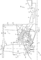
- FIG. 1 Illustrated in FIG. 1 is an exemplary aircraft turbofan gas turbine engine 10 circumscribed about an engine centerline axis 12 and suitably designed to be mounted to a wing or fuselage of an aircraft.
- the engine 10 includes, in downstream serial flow communication, a fan 14, a low pressure compressor or booster 16, a high pressure compressor 18, a combustor 20, a high pressure turbine (HPT) 22, and a low pressure turbine (LPT) 24.
- a core engine 25 includes the HPT or high pressure turbine 22 drivingly connected by a high pressure drive shaft 23 to the high pressure compressor 18 and the combustor 20.
- the LPT or low pressure turbine 24 is drivingly connected by a low pressure drive shaft 26 to both the fan 14 and the booster 16.
- the fan 14 may be rotated about the engine centerline axis 12 by the low pressure drive shaft 26.
- the fan 14 is a variable pitch fan 38 having a plurality of variable pitch fan blades 60 coupled to and extending radially outwardly from a disk 62 as illustrated in FIG. 1 .
- Each fan blade 60 is pivotable or rotatable about a pitch axis P perpendicular or normal to the centerline axis 12.
- a pitch actuation mechanism 66 is operable to vary the pitch of the fan blades 60 in unison.
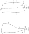
- each fan blade 60 includes an airfoil 200 extending radially outwardly from a blade base or platform 202 to an airfoil tip 203.
- the airfoil 200 includes pressure and suction sides 205, 207 extending downstream from a leading edge LE to a trailing edge TE of each of the airfoils 200.
- a blade root 204 extends radially inwardly from the blade base or platform 202.
- a fan blade pin or shaft 206 extends radially inwardly from the blade root 204, is rotatably mounted in the disk 62, and is centered and circumscribed about the pitch axis P.
- a blade turning lever 210 is connected to the fan blade 60 near the blade base or platform 202. The turning lever 210 may be attached to or be integral and monolithic with the blade root 204 and extend away from the pressure or suction side 205, 207 of the airfoil 200.
- a spider link 212 includes a spider ring 214 with thrust transmitting spider arms 216 disposed around and extending away from the spider ring 214 towards the blade roots 204 and the turning levers 210. There is a one to one numerical relationship between spider arms 216 and the fan blades 60.
- the spider ring 214 is connected to one or more linear actuators 70 of the pitch actuation mechanism 66.
- the linear actuators 70 may be hydraulic or electric actuators, non-rotatably mounted parallel to the engine centerline axis 12 and grounded or connected to non-rotatable fan structure such as a fan hub frame 56.
- the actuators 70 are connected to the spider ring 214 through thrust bearings 80 that enables transmission of axial displacement of non-rotatable actuator rods 220 of the actuators 70 while the fan blades 60 are rotating.
- a preferred number of the actuators 70 is four.
- An inner race 222 of each of the thrust bearings 80 is attached to the spider ring 214.
- the actuators 70 are located in a rotor 73 of the engine 10 radially inwardly of the booster 16.
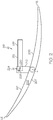
- FIG. 2 illustrates how the turning lever 210 is connected and cammed to the spider arm 216 by a pin and slot joint 224.
- the turning lever 210 may include a joint slot 228 and the spider arm 216 may include a joint pin 226 that is disposed through the joint slot 228.
- the slot may be angled or curved to provide camming of the turning lever 210 with respect to the spider arm 216.
- the turning lever 210 is orthogonal or perpendicular to the engine centerline axis 12 and the pitch axis P. Referring to FIG.
- the position or pitch of the fan blade 60 can be defined in relation to a length of the actuator rods 220 that is translated in the axial direction.
- air 27 is pressurized by the fan 14 and produces an inner or core airflow 15 channeled through the booster 16 which further pressurizes the core airflow 15.
- the pressurized air of the core airflow 15 is then flowed to the high pressure compressor 18 which further pressurizes the air.
- the pressurized air is mixed with fuel in the combustor 20 for generating hot combustion gases 28 that flow downstream, in turn, through the HPT 22 and the LPT 24.
- Engine bearings (not shown) rotatably support the high pressure compressor 18 and the HPT 22 and rotatably support the fan 14 and the LPT 24.
- a flow splitter 34 surrounding the booster 16 immediately behind the fan 14 includes a sharp leading edge 32 which splits the fan air 27 pressurized by the fan 14 into a radially inner stream (core airflow 15) channeled through the booster 16 and a radially outer stream or bypass airflow 17 is channeled into a bypass flow path 35 through a bypass duct 36 spaced radially outwardly from the booster 16.
- a fan casing 30 surrounding the fan 14 and the bypass duct 36 is supported by an annular fan frame 33 circumscribed about the engine centerline axis 12.
- the fan hub frame 56 is part of or connected to the fan frame 33.
- the booster 16 includes alternating annular rows of booster blades and vanes 37, 42 extending radially outwardly and inwardly across a booster flowpath 39 in a booster duct 40.
- the annular row of booster blades 37 are suitably joined to the low pressure drive shaft 26.
- the booster 16 is located forward of the fan frame 33 and radially inboard of the flow splitter 34.
- the fan frame 33 includes an annular outer frame casing 54, the fan hub frame 56, and a plurality of circumferentially spaced apart duct struts 58 extending therebetween.
- the duct struts 58 are airfoil shaped.
Landscapes
- Engineering & Computer Science (AREA)
- Mechanical Engineering (AREA)
- General Engineering & Computer Science (AREA)
- Chemical & Material Sciences (AREA)
- Combustion & Propulsion (AREA)
- Structures Of Non-Positive Displacement Pumps (AREA)
Applications Claiming Priority (1)
| Application Number | Priority Date | Filing Date | Title |
|---|---|---|---|
| US15/646,460 US10801339B2 (en) | 2017-07-11 | 2017-07-11 | Aircraft gas turbine engine variable fan blade mechanism |
Publications (2)
| Publication Number | Publication Date |
|---|---|
| EP3428400A1 true EP3428400A1 (fr) | 2019-01-16 |
| EP3428400B1 EP3428400B1 (fr) | 2020-10-21 |
Family
ID=62837746
Family Applications (1)
| Application Number | Title | Priority Date | Filing Date |
|---|---|---|---|
| EP18180819.7A Active EP3428400B1 (fr) | 2017-07-11 | 2018-06-29 | Mécanisme de pale de soufflante variable de moteur à turbine à gaz d'aéronef |
Country Status (5)
| Country | Link |
|---|---|
| US (1) | US10801339B2 (fr) |
| EP (1) | EP3428400B1 (fr) |
| JP (1) | JP2019049256A (fr) |
| CN (1) | CN109236739B (fr) |
| CA (1) | CA3009749C (fr) |
Families Citing this family (6)
| Publication number | Priority date | Publication date | Assignee | Title |
|---|---|---|---|---|
| US10473111B2 (en) * | 2017-10-18 | 2019-11-12 | Rolls-Royce Corporation | Variable pitch fan for a gas turbine engine |
| US11208905B2 (en) | 2019-05-24 | 2021-12-28 | Johnson Controls Technology Company | Fan assembly for an HVAC system |
| FR3123949B1 (fr) | 2021-06-10 | 2024-05-03 | Safran Aircraft Engines | Ensemble d’un carter de soufflante d’une turbomachine et d’une entrée d’air, procédé d’utilisation d’un tel ensemble |
| US11608743B1 (en) | 2022-02-04 | 2023-03-21 | General Electric Company | Low-noise blade for an open rotor |
| US12049306B2 (en) | 2022-02-04 | 2024-07-30 | General Electric Company | Low-noise blade for an open rotor |
| US11913355B2 (en) * | 2022-02-14 | 2024-02-27 | General Electric Company | Part-span shrouds for pitch controlled aircrafts |
Citations (4)
| Publication number | Priority date | Publication date | Assignee | Title |
|---|---|---|---|---|
| US3873236A (en) * | 1973-12-26 | 1975-03-25 | Gen Electric | Fan with variable pitch blades and translating bearing actuation system |
| EP3168480A1 (fr) * | 2015-11-16 | 2017-05-17 | General Electric Company | Soufflante de moteur d'avion à pas variable avec rapport de solidité élevé et plage de pas étendue |
| EP3170985A1 (fr) * | 2015-11-17 | 2017-05-24 | General Electric Company | Actionneur de soufflante comprenant d'aubes variables |
| FR3046433A1 (fr) * | 2016-01-05 | 2017-07-07 | Snecma | Module de soufflante a aubes a calage variable pour une turbomachine |
Family Cites Families (24)
| Publication number | Priority date | Publication date | Assignee | Title |
|---|---|---|---|---|
| CH457976A (fr) | 1966-05-25 | 1968-06-15 | Dowty Rotol Ltd | Turbopropulseur |
| DE2307656C3 (de) * | 1973-02-16 | 1979-01-04 | Motoren- Und Turbinen-Union Muenchen Gmbh, 8000 Muenchen | Vorrichtung zur Verstellung der Gebläselaufschaufeln eines Laufrades für Turbinenstrahltriebwerke |
| US3870434A (en) | 1973-12-21 | 1975-03-11 | Gen Electric | Gear arrangement for variable pitch fan |
| US3866415A (en) | 1974-02-25 | 1975-02-18 | Gen Electric | Fan blade actuator using pressurized air |
| US4021142A (en) * | 1974-10-09 | 1977-05-03 | United Technologies Corporation | Pitch-change apparatus for a ducted thrust fan |
| US4842484A (en) | 1983-08-29 | 1989-06-27 | General Electric Company | Blade gearing and pitch changing mechanisms for coaxial counterrotating propellers |
| US4657484A (en) * | 1984-09-04 | 1987-04-14 | General Electric Company | Blade pitch varying means |
| US4662819A (en) | 1986-04-10 | 1987-05-05 | American Standard Inc. | Centrifugal fan with variable blade pitch |
| US4753572A (en) | 1986-10-02 | 1988-06-28 | United Technologies Corporation | Propeller pitch change actuation system |
| US4927329A (en) | 1988-10-21 | 1990-05-22 | General Electric Company | Aircraft engine unducted fan blade pitch control system |
| DE3837994A1 (de) | 1988-11-09 | 1990-05-10 | Mtu Muenchen Gmbh | Vorrichtung zur verstellung der rotorschaufeln eines propfan/turboproptriebwerkes |
| US5174716A (en) | 1990-07-23 | 1992-12-29 | General Electric Company | Pitch change mechanism |
| US5282719A (en) | 1991-05-13 | 1994-02-01 | Alliedsignal Inc. | Quad mode fan pitch actuation system for a gas turbine engine |
| FR2712250B1 (fr) | 1993-11-10 | 1995-12-29 | Hispano Suiza Sa | Procédé et dispositif de commande de variation du pas des pales d'un rotor. |
| US7264203B2 (en) | 2003-10-02 | 2007-09-04 | The Nordam Group, Inc. | Spider actuated thrust reverser |
| WO2006086342A2 (fr) | 2005-02-07 | 2006-08-17 | Aerocomposites, Inc. | Pale de rotor a pas variable presentant des doubles elements de retenue souples |
| FR2911930A1 (fr) | 2007-01-26 | 2008-08-01 | Snecma Sa | Turbopropulseur a helice a pas reglable |
| JP2011521153A (ja) | 2008-05-13 | 2011-07-21 | ローテイティング コンポジット テクノロジーズ, エルエルシー | ファンブレードの保持および可変ピッチのためのシステム |
| RU2523928C2 (ru) | 2009-02-27 | 2014-07-27 | Снекма | Лопатки вентилятора с изменяемым углом установки |
| FR2945512B1 (fr) | 2009-05-15 | 2012-08-24 | Snecma | Helice non carenee a pales a calage variable pour une turbomachine |
| US8496436B2 (en) | 2010-01-11 | 2013-07-30 | Hamilton Sundstrand Corporation | Torque compensation for propeller pitch change mechanism |
| DE102010039394A1 (de) | 2010-08-17 | 2012-02-23 | Siemens Aktiengesellschaft | Verstellpropeller oder -repeller |
| FR2997138B1 (fr) | 2012-10-18 | 2014-11-14 | Snecma | Dispositif et procede de commande du calage des pales |
| FR3001264B1 (fr) | 2013-01-18 | 2017-03-17 | Snecma | Systeme pour changer le pas des pales d'une helice. |
-
2017
- 2017-07-11 US US15/646,460 patent/US10801339B2/en active Active
-
2018
- 2018-06-28 CA CA3009749A patent/CA3009749C/fr active Active
- 2018-06-29 CN CN201810722333.3A patent/CN109236739B/zh active Active
- 2018-06-29 EP EP18180819.7A patent/EP3428400B1/fr active Active
- 2018-07-06 JP JP2018128742A patent/JP2019049256A/ja active Pending
Patent Citations (4)
| Publication number | Priority date | Publication date | Assignee | Title |
|---|---|---|---|---|
| US3873236A (en) * | 1973-12-26 | 1975-03-25 | Gen Electric | Fan with variable pitch blades and translating bearing actuation system |
| EP3168480A1 (fr) * | 2015-11-16 | 2017-05-17 | General Electric Company | Soufflante de moteur d'avion à pas variable avec rapport de solidité élevé et plage de pas étendue |
| EP3170985A1 (fr) * | 2015-11-17 | 2017-05-24 | General Electric Company | Actionneur de soufflante comprenant d'aubes variables |
| FR3046433A1 (fr) * | 2016-01-05 | 2017-07-07 | Snecma | Module de soufflante a aubes a calage variable pour une turbomachine |
Also Published As
| Publication number | Publication date |
|---|---|
| CA3009749C (fr) | 2020-06-02 |
| CA3009749A1 (fr) | 2019-01-11 |
| CN109236739A (zh) | 2019-01-18 |
| US10801339B2 (en) | 2020-10-13 |
| CN109236739B (zh) | 2021-07-27 |
| US20190017396A1 (en) | 2019-01-17 |
| JP2019049256A (ja) | 2019-03-28 |
| EP3428400B1 (fr) | 2020-10-21 |
Similar Documents
| Publication | Publication Date | Title |
|---|---|---|
| EP3428400B1 (fr) | Mécanisme de pale de soufflante variable de moteur à turbine à gaz d'aéronef | |
| US20240368997A1 (en) | Unducted thrust producing system architecture | |
| CN107956598B (zh) | 燃气涡轮发动机 | |
| EP3093451A1 (fr) | Agencement de joint de bout d'aube, moteur à turbine à gaz et procédé de réglage associés | |
| EP3722565B1 (fr) | Système post-ventilateur pour un moteur à turbine à gaz | |
| US20210108523A1 (en) | Unducted single rotor engine | |
| US12140040B2 (en) | Airfoil assembly with a differentially oriented stage | |
| US11634993B2 (en) | Gas turbine engine with improved VIGV shielding | |
| US12535007B2 (en) | Cover plate connections for a hollow fan blade | |
| EP3628828A1 (fr) | Ensemble de boîtier pour moteur de turbine à gaz | |
| CN112443364B (zh) | 用于同心可变定子静叶的促动组件 | |
| US20260078680A1 (en) | Pitch change mechanism for a fan of a gas turbine engine | |
| CN115853826B (zh) | 具有中跨护罩的风扇叶片组件 | |
| US11913355B2 (en) | Part-span shrouds for pitch controlled aircrafts | |
| CN118088490A (zh) | 翼型组件 | |
| EP3170973B1 (fr) | Écoulement de l'air dans une turbomachine | |
| US20240110522A1 (en) | Shaft coupling for a gas turbine engine | |
| US12618329B2 (en) | Unducted airfoil assembly | |
| US20240328320A1 (en) | Unducted airfoil assembly | |
| GB2589098A (en) | Variable vane mechanism |
Legal Events
| Date | Code | Title | Description |
|---|---|---|---|
| STAA | Information on the status of an ep patent application or granted ep patent |
Free format text: STATUS: UNKNOWN |
|
| PUAI | Public reference made under article 153(3) epc to a published international application that has entered the european phase |
Free format text: ORIGINAL CODE: 0009012 |
|
| STAA | Information on the status of an ep patent application or granted ep patent |
Free format text: STATUS: THE APPLICATION HAS BEEN PUBLISHED |
|
| AK | Designated contracting states |
Kind code of ref document: A1 Designated state(s): AL AT BE BG CH CY CZ DE DK EE ES FI FR GB GR HR HU IE IS IT LI LT LU LV MC MK MT NL NO PL PT RO RS SE SI SK SM TR |
|
| AX | Request for extension of the european patent |
Extension state: BA ME |
|
| STAA | Information on the status of an ep patent application or granted ep patent |
Free format text: STATUS: REQUEST FOR EXAMINATION WAS MADE |
|
| 17P | Request for examination filed |
Effective date: 20190716 |
|
| RBV | Designated contracting states (corrected) |
Designated state(s): AL AT BE BG CH CY CZ DE DK EE ES FI FR GB GR HR HU IE IS IT LI LT LU LV MC MK MT NL NO PL PT RO RS SE SI SK SM TR |
|
| RIC1 | Information provided on ipc code assigned before grant |
Ipc: F01D 7/00 20060101AFI20191004BHEP Ipc: F01D 7/02 20060101ALI20191004BHEP |
|
| GRAP | Despatch of communication of intention to grant a patent |
Free format text: ORIGINAL CODE: EPIDOSNIGR1 |
|
| STAA | Information on the status of an ep patent application or granted ep patent |
Free format text: STATUS: GRANT OF PATENT IS INTENDED |
|
| INTG | Intention to grant announced |
Effective date: 20191127 |
|
| GRAJ | Information related to disapproval of communication of intention to grant by the applicant or resumption of examination proceedings by the epo deleted |
Free format text: ORIGINAL CODE: EPIDOSDIGR1 |
|
| STAA | Information on the status of an ep patent application or granted ep patent |
Free format text: STATUS: REQUEST FOR EXAMINATION WAS MADE |
|
| INTC | Intention to grant announced (deleted) | ||
| GRAP | Despatch of communication of intention to grant a patent |
Free format text: ORIGINAL CODE: EPIDOSNIGR1 |
|
| STAA | Information on the status of an ep patent application or granted ep patent |
Free format text: STATUS: GRANT OF PATENT IS INTENDED |
|
| INTG | Intention to grant announced |
Effective date: 20200515 |
|
| GRAS | Grant fee paid |
Free format text: ORIGINAL CODE: EPIDOSNIGR3 |
|
| GRAA | (expected) grant |
Free format text: ORIGINAL CODE: 0009210 |
|
| STAA | Information on the status of an ep patent application or granted ep patent |
Free format text: STATUS: THE PATENT HAS BEEN GRANTED |
|
| AK | Designated contracting states |
Kind code of ref document: B1 Designated state(s): AL AT BE BG CH CY CZ DE DK EE ES FI FR GB GR HR HU IE IS IT LI LT LU LV MC MK MT NL NO PL PT RO RS SE SI SK SM TR |
|
| REG | Reference to a national code |
Ref country code: GB Ref legal event code: FG4D |
|
| REG | Reference to a national code |
Ref country code: CH Ref legal event code: EP |
|
| REG | Reference to a national code |
Ref country code: IE Ref legal event code: FG4D |
|
| REG | Reference to a national code |
Ref country code: DE Ref legal event code: R096 Ref document number: 602018008846 Country of ref document: DE |
|
| REG | Reference to a national code |
Ref country code: AT Ref legal event code: REF Ref document number: 1326047 Country of ref document: AT Kind code of ref document: T Effective date: 20201115 |
|
| REG | Reference to a national code |
Ref country code: AT Ref legal event code: MK05 Ref document number: 1326047 Country of ref document: AT Kind code of ref document: T Effective date: 20201021 |
|
| REG | Reference to a national code |
Ref country code: NL Ref legal event code: MP Effective date: 20201021 |
|
| PG25 | Lapsed in a contracting state [announced via postgrant information from national office to epo] |
Ref country code: RS Free format text: LAPSE BECAUSE OF FAILURE TO SUBMIT A TRANSLATION OF THE DESCRIPTION OR TO PAY THE FEE WITHIN THE PRESCRIBED TIME-LIMIT Effective date: 20201021 Ref country code: PT Free format text: LAPSE BECAUSE OF FAILURE TO SUBMIT A TRANSLATION OF THE DESCRIPTION OR TO PAY THE FEE WITHIN THE PRESCRIBED TIME-LIMIT Effective date: 20210222 Ref country code: FI Free format text: LAPSE BECAUSE OF FAILURE TO SUBMIT A TRANSLATION OF THE DESCRIPTION OR TO PAY THE FEE WITHIN THE PRESCRIBED TIME-LIMIT Effective date: 20201021 Ref country code: NO Free format text: LAPSE BECAUSE OF FAILURE TO SUBMIT A TRANSLATION OF THE DESCRIPTION OR TO PAY THE FEE WITHIN THE PRESCRIBED TIME-LIMIT Effective date: 20210121 Ref country code: GR Free format text: LAPSE BECAUSE OF FAILURE TO SUBMIT A TRANSLATION OF THE DESCRIPTION OR TO PAY THE FEE WITHIN THE PRESCRIBED TIME-LIMIT Effective date: 20210122 |
|
| REG | Reference to a national code |
Ref country code: LT Ref legal event code: MG4D |
|
| PG25 | Lapsed in a contracting state [announced via postgrant information from national office to epo] |
Ref country code: AT Free format text: LAPSE BECAUSE OF FAILURE TO SUBMIT A TRANSLATION OF THE DESCRIPTION OR TO PAY THE FEE WITHIN THE PRESCRIBED TIME-LIMIT Effective date: 20201021 Ref country code: ES Free format text: LAPSE BECAUSE OF FAILURE TO SUBMIT A TRANSLATION OF THE DESCRIPTION OR TO PAY THE FEE WITHIN THE PRESCRIBED TIME-LIMIT Effective date: 20201021 Ref country code: BG Free format text: LAPSE BECAUSE OF FAILURE TO SUBMIT A TRANSLATION OF THE DESCRIPTION OR TO PAY THE FEE WITHIN THE PRESCRIBED TIME-LIMIT Effective date: 20210121 Ref country code: SE Free format text: LAPSE BECAUSE OF FAILURE TO SUBMIT A TRANSLATION OF THE DESCRIPTION OR TO PAY THE FEE WITHIN THE PRESCRIBED TIME-LIMIT Effective date: 20201021 Ref country code: LV Free format text: LAPSE BECAUSE OF FAILURE TO SUBMIT A TRANSLATION OF THE DESCRIPTION OR TO PAY THE FEE WITHIN THE PRESCRIBED TIME-LIMIT Effective date: 20201021 Ref country code: PL Free format text: LAPSE BECAUSE OF FAILURE TO SUBMIT A TRANSLATION OF THE DESCRIPTION OR TO PAY THE FEE WITHIN THE PRESCRIBED TIME-LIMIT Effective date: 20201021 Ref country code: IS Free format text: LAPSE BECAUSE OF FAILURE TO SUBMIT A TRANSLATION OF THE DESCRIPTION OR TO PAY THE FEE WITHIN THE PRESCRIBED TIME-LIMIT Effective date: 20210221 |
|
| PG25 | Lapsed in a contracting state [announced via postgrant information from national office to epo] |
Ref country code: NL Free format text: LAPSE BECAUSE OF FAILURE TO SUBMIT A TRANSLATION OF THE DESCRIPTION OR TO PAY THE FEE WITHIN THE PRESCRIBED TIME-LIMIT Effective date: 20201021 Ref country code: HR Free format text: LAPSE BECAUSE OF FAILURE TO SUBMIT A TRANSLATION OF THE DESCRIPTION OR TO PAY THE FEE WITHIN THE PRESCRIBED TIME-LIMIT Effective date: 20201021 |
|
| REG | Reference to a national code |
Ref country code: DE Ref legal event code: R097 Ref document number: 602018008846 Country of ref document: DE |
|
| PG25 | Lapsed in a contracting state [announced via postgrant information from national office to epo] |
Ref country code: RO Free format text: LAPSE BECAUSE OF FAILURE TO SUBMIT A TRANSLATION OF THE DESCRIPTION OR TO PAY THE FEE WITHIN THE PRESCRIBED TIME-LIMIT Effective date: 20201021 Ref country code: SK Free format text: LAPSE BECAUSE OF FAILURE TO SUBMIT A TRANSLATION OF THE DESCRIPTION OR TO PAY THE FEE WITHIN THE PRESCRIBED TIME-LIMIT Effective date: 20201021 Ref country code: LT Free format text: LAPSE BECAUSE OF FAILURE TO SUBMIT A TRANSLATION OF THE DESCRIPTION OR TO PAY THE FEE WITHIN THE PRESCRIBED TIME-LIMIT Effective date: 20201021 Ref country code: SM Free format text: LAPSE BECAUSE OF FAILURE TO SUBMIT A TRANSLATION OF THE DESCRIPTION OR TO PAY THE FEE WITHIN THE PRESCRIBED TIME-LIMIT Effective date: 20201021 Ref country code: CZ Free format text: LAPSE BECAUSE OF FAILURE TO SUBMIT A TRANSLATION OF THE DESCRIPTION OR TO PAY THE FEE WITHIN THE PRESCRIBED TIME-LIMIT Effective date: 20201021 Ref country code: EE Free format text: LAPSE BECAUSE OF FAILURE TO SUBMIT A TRANSLATION OF THE DESCRIPTION OR TO PAY THE FEE WITHIN THE PRESCRIBED TIME-LIMIT Effective date: 20201021 |
|
| PLBE | No opposition filed within time limit |
Free format text: ORIGINAL CODE: 0009261 |
|
| STAA | Information on the status of an ep patent application or granted ep patent |
Free format text: STATUS: NO OPPOSITION FILED WITHIN TIME LIMIT |
|
| PG25 | Lapsed in a contracting state [announced via postgrant information from national office to epo] |
Ref country code: DK Free format text: LAPSE BECAUSE OF FAILURE TO SUBMIT A TRANSLATION OF THE DESCRIPTION OR TO PAY THE FEE WITHIN THE PRESCRIBED TIME-LIMIT Effective date: 20201021 |
|
| 26N | No opposition filed |
Effective date: 20210722 |
|
| PG25 | Lapsed in a contracting state [announced via postgrant information from national office to epo] |
Ref country code: AL Free format text: LAPSE BECAUSE OF FAILURE TO SUBMIT A TRANSLATION OF THE DESCRIPTION OR TO PAY THE FEE WITHIN THE PRESCRIBED TIME-LIMIT Effective date: 20201021 Ref country code: IT Free format text: LAPSE BECAUSE OF FAILURE TO SUBMIT A TRANSLATION OF THE DESCRIPTION OR TO PAY THE FEE WITHIN THE PRESCRIBED TIME-LIMIT Effective date: 20201021 |
|
| PG25 | Lapsed in a contracting state [announced via postgrant information from national office to epo] |
Ref country code: SI Free format text: LAPSE BECAUSE OF FAILURE TO SUBMIT A TRANSLATION OF THE DESCRIPTION OR TO PAY THE FEE WITHIN THE PRESCRIBED TIME-LIMIT Effective date: 20201021 |
|
| PG25 | Lapsed in a contracting state [announced via postgrant information from national office to epo] |
Ref country code: MC Free format text: LAPSE BECAUSE OF FAILURE TO SUBMIT A TRANSLATION OF THE DESCRIPTION OR TO PAY THE FEE WITHIN THE PRESCRIBED TIME-LIMIT Effective date: 20201021 |
|
| REG | Reference to a national code |
Ref country code: CH Ref legal event code: PL |
|
| REG | Reference to a national code |
Ref country code: BE Ref legal event code: MM Effective date: 20210630 |
|
| PG25 | Lapsed in a contracting state [announced via postgrant information from national office to epo] |
Ref country code: LU Free format text: LAPSE BECAUSE OF NON-PAYMENT OF DUE FEES Effective date: 20210629 |
|
| PG25 | Lapsed in a contracting state [announced via postgrant information from national office to epo] |
Ref country code: LI Free format text: LAPSE BECAUSE OF NON-PAYMENT OF DUE FEES Effective date: 20210630 Ref country code: IE Free format text: LAPSE BECAUSE OF NON-PAYMENT OF DUE FEES Effective date: 20210629 Ref country code: CH Free format text: LAPSE BECAUSE OF NON-PAYMENT OF DUE FEES Effective date: 20210630 |
|
| PG25 | Lapsed in a contracting state [announced via postgrant information from national office to epo] |
Ref country code: IS Free format text: LAPSE BECAUSE OF FAILURE TO SUBMIT A TRANSLATION OF THE DESCRIPTION OR TO PAY THE FEE WITHIN THE PRESCRIBED TIME-LIMIT Effective date: 20210221 |
|
| PG25 | Lapsed in a contracting state [announced via postgrant information from national office to epo] |
Ref country code: BE Free format text: LAPSE BECAUSE OF NON-PAYMENT OF DUE FEES Effective date: 20210630 |
|
| P01 | Opt-out of the competence of the unified patent court (upc) registered |
Effective date: 20230414 |
|
| PG25 | Lapsed in a contracting state [announced via postgrant information from national office to epo] |
Ref country code: CY Free format text: LAPSE BECAUSE OF FAILURE TO SUBMIT A TRANSLATION OF THE DESCRIPTION OR TO PAY THE FEE WITHIN THE PRESCRIBED TIME-LIMIT Effective date: 20201021 |
|
| PG25 | Lapsed in a contracting state [announced via postgrant information from national office to epo] |
Ref country code: HU Free format text: LAPSE BECAUSE OF FAILURE TO SUBMIT A TRANSLATION OF THE DESCRIPTION OR TO PAY THE FEE WITHIN THE PRESCRIBED TIME-LIMIT; INVALID AB INITIO Effective date: 20180629 |
|
| PG25 | Lapsed in a contracting state [announced via postgrant information from national office to epo] |
Ref country code: MK Free format text: LAPSE BECAUSE OF FAILURE TO SUBMIT A TRANSLATION OF THE DESCRIPTION OR TO PAY THE FEE WITHIN THE PRESCRIBED TIME-LIMIT Effective date: 20201021 |
|
| PG25 | Lapsed in a contracting state [announced via postgrant information from national office to epo] |
Ref country code: TR Free format text: LAPSE BECAUSE OF FAILURE TO SUBMIT A TRANSLATION OF THE DESCRIPTION OR TO PAY THE FEE WITHIN THE PRESCRIBED TIME-LIMIT Effective date: 20201021 |
|
| PG25 | Lapsed in a contracting state [announced via postgrant information from national office to epo] |
Ref country code: MT Free format text: LAPSE BECAUSE OF FAILURE TO SUBMIT A TRANSLATION OF THE DESCRIPTION OR TO PAY THE FEE WITHIN THE PRESCRIBED TIME-LIMIT Effective date: 20201021 |
|
| PGFP | Annual fee paid to national office [announced via postgrant information from national office to epo] |
Ref country code: DE Payment date: 20250520 Year of fee payment: 8 |
|
| PGFP | Annual fee paid to national office [announced via postgrant information from national office to epo] |
Ref country code: GB Payment date: 20250520 Year of fee payment: 8 |
|
| PGFP | Annual fee paid to national office [announced via postgrant information from national office to epo] |
Ref country code: FR Payment date: 20250521 Year of fee payment: 8 |