EP3428450B1 - Pumpe mit variabler verdrängung - Google Patents
Pumpe mit variabler verdrängung Download PDFInfo
- Publication number
- EP3428450B1 EP3428450B1 EP17762782.5A EP17762782A EP3428450B1 EP 3428450 B1 EP3428450 B1 EP 3428450B1 EP 17762782 A EP17762782 A EP 17762782A EP 3428450 B1 EP3428450 B1 EP 3428450B1
- Authority
- EP
- European Patent Office
- Prior art keywords
- pump
- chamber
- pressure
- control hydraulic
- variable displacement
- Prior art date
- Legal status (The legal status is an assumption and is not a legal conclusion. Google has not performed a legal analysis and makes no representation as to the accuracy of the status listed.)
- Active
Links
Images



Classifications
-
- F—MECHANICAL ENGINEERING; LIGHTING; HEATING; WEAPONS; BLASTING
- F04—POSITIVE - DISPLACEMENT MACHINES FOR LIQUIDS; PUMPS FOR LIQUIDS OR ELASTIC FLUIDS
- F04C—ROTARY-PISTON, OR OSCILLATING-PISTON, POSITIVE-DISPLACEMENT MACHINES FOR LIQUIDS; ROTARY-PISTON, OR OSCILLATING-PISTON, POSITIVE-DISPLACEMENT PUMPS
- F04C14/00—Control of, monitoring of, or safety arrangements for, machines, pumps or pumping installations
- F04C14/18—Control of, monitoring of, or safety arrangements for, machines, pumps or pumping installations characterised by varying the volume of the working chamber
- F04C14/22—Control of, monitoring of, or safety arrangements for, machines, pumps or pumping installations characterised by varying the volume of the working chamber by changing the eccentricity between cooperating members
- F04C14/223—Control of, monitoring of, or safety arrangements for, machines, pumps or pumping installations characterised by varying the volume of the working chamber by changing the eccentricity between cooperating members using a movable cam
- F04C14/226—Control of, monitoring of, or safety arrangements for, machines, pumps or pumping installations characterised by varying the volume of the working chamber by changing the eccentricity between cooperating members using a movable cam by pivoting the cam around an eccentric axis
-
- F—MECHANICAL ENGINEERING; LIGHTING; HEATING; WEAPONS; BLASTING
- F04—POSITIVE - DISPLACEMENT MACHINES FOR LIQUIDS; PUMPS FOR LIQUIDS OR ELASTIC FLUIDS
- F04C—ROTARY-PISTON, OR OSCILLATING-PISTON, POSITIVE-DISPLACEMENT MACHINES FOR LIQUIDS; ROTARY-PISTON, OR OSCILLATING-PISTON, POSITIVE-DISPLACEMENT PUMPS
- F04C2/00—Rotary-piston machines or pumps
- F04C2/30—Rotary-piston machines or pumps having the characteristics covered by two or more groups F04C2/02, F04C2/08, F04C2/22, F04C2/24 or having the characteristics covered by one of these groups together with some other type of movement between co-operating members
- F04C2/34—Rotary-piston machines or pumps having the characteristics covered by two or more groups F04C2/02, F04C2/08, F04C2/22, F04C2/24 or having the characteristics covered by one of these groups together with some other type of movement between co-operating members having the movement defined in groups F04C2/08 or F04C2/22 and relative reciprocation between the co-operating members
- F04C2/344—Rotary-piston machines or pumps having the characteristics covered by two or more groups F04C2/02, F04C2/08, F04C2/22, F04C2/24 or having the characteristics covered by one of these groups together with some other type of movement between co-operating members having the movement defined in groups F04C2/08 or F04C2/22 and relative reciprocation between the co-operating members with vanes reciprocating with respect to the inner member
-
- F—MECHANICAL ENGINEERING; LIGHTING; HEATING; WEAPONS; BLASTING
- F04—POSITIVE - DISPLACEMENT MACHINES FOR LIQUIDS; PUMPS FOR LIQUIDS OR ELASTIC FLUIDS
- F04C—ROTARY-PISTON, OR OSCILLATING-PISTON, POSITIVE-DISPLACEMENT MACHINES FOR LIQUIDS; ROTARY-PISTON, OR OSCILLATING-PISTON, POSITIVE-DISPLACEMENT PUMPS
- F04C14/00—Control of, monitoring of, or safety arrangements for, machines, pumps or pumping installations
-
- F—MECHANICAL ENGINEERING; LIGHTING; HEATING; WEAPONS; BLASTING
- F04—POSITIVE - DISPLACEMENT MACHINES FOR LIQUIDS; PUMPS FOR LIQUIDS OR ELASTIC FLUIDS
- F04C—ROTARY-PISTON, OR OSCILLATING-PISTON, POSITIVE-DISPLACEMENT MACHINES FOR LIQUIDS; ROTARY-PISTON, OR OSCILLATING-PISTON, POSITIVE-DISPLACEMENT PUMPS
- F04C14/00—Control of, monitoring of, or safety arrangements for, machines, pumps or pumping installations
- F04C14/18—Control of, monitoring of, or safety arrangements for, machines, pumps or pumping installations characterised by varying the volume of the working chamber
- F04C14/22—Control of, monitoring of, or safety arrangements for, machines, pumps or pumping installations characterised by varying the volume of the working chamber by changing the eccentricity between cooperating members
- F04C14/223—Control of, monitoring of, or safety arrangements for, machines, pumps or pumping installations characterised by varying the volume of the working chamber by changing the eccentricity between cooperating members using a movable cam
-
- F—MECHANICAL ENGINEERING; LIGHTING; HEATING; WEAPONS; BLASTING
- F04—POSITIVE - DISPLACEMENT MACHINES FOR LIQUIDS; PUMPS FOR LIQUIDS OR ELASTIC FLUIDS
- F04C—ROTARY-PISTON, OR OSCILLATING-PISTON, POSITIVE-DISPLACEMENT MACHINES FOR LIQUIDS; ROTARY-PISTON, OR OSCILLATING-PISTON, POSITIVE-DISPLACEMENT PUMPS
- F04C15/00—Component parts, details or accessories of machines, pumps or pumping installations, not provided for in groups F04C2/00 - F04C14/00
-
- F—MECHANICAL ENGINEERING; LIGHTING; HEATING; WEAPONS; BLASTING
- F04—POSITIVE - DISPLACEMENT MACHINES FOR LIQUIDS; PUMPS FOR LIQUIDS OR ELASTIC FLUIDS
- F04C—ROTARY-PISTON, OR OSCILLATING-PISTON, POSITIVE-DISPLACEMENT MACHINES FOR LIQUIDS; ROTARY-PISTON, OR OSCILLATING-PISTON, POSITIVE-DISPLACEMENT PUMPS
- F04C15/00—Component parts, details or accessories of machines, pumps or pumping installations, not provided for in groups F04C2/00 - F04C14/00
- F04C15/06—Arrangements for admission or discharge of the working fluid, e.g. constructional features of the inlet or outlet
-
- F—MECHANICAL ENGINEERING; LIGHTING; HEATING; WEAPONS; BLASTING
- F04—POSITIVE - DISPLACEMENT MACHINES FOR LIQUIDS; PUMPS FOR LIQUIDS OR ELASTIC FLUIDS
- F04C—ROTARY-PISTON, OR OSCILLATING-PISTON, POSITIVE-DISPLACEMENT MACHINES FOR LIQUIDS; ROTARY-PISTON, OR OSCILLATING-PISTON, POSITIVE-DISPLACEMENT PUMPS
- F04C2/00—Rotary-piston machines or pumps
- F04C2/30—Rotary-piston machines or pumps having the characteristics covered by two or more groups F04C2/02, F04C2/08, F04C2/22, F04C2/24 or having the characteristics covered by one of these groups together with some other type of movement between co-operating members
- F04C2/34—Rotary-piston machines or pumps having the characteristics covered by two or more groups F04C2/02, F04C2/08, F04C2/22, F04C2/24 or having the characteristics covered by one of these groups together with some other type of movement between co-operating members having the movement defined in groups F04C2/08 or F04C2/22 and relative reciprocation between the co-operating members
- F04C2/344—Rotary-piston machines or pumps having the characteristics covered by two or more groups F04C2/02, F04C2/08, F04C2/22, F04C2/24 or having the characteristics covered by one of these groups together with some other type of movement between co-operating members having the movement defined in groups F04C2/08 or F04C2/22 and relative reciprocation between the co-operating members with vanes reciprocating with respect to the inner member
- F04C2/3441—Rotary-piston machines or pumps having the characteristics covered by two or more groups F04C2/02, F04C2/08, F04C2/22, F04C2/24 or having the characteristics covered by one of these groups together with some other type of movement between co-operating members having the movement defined in groups F04C2/08 or F04C2/22 and relative reciprocation between the co-operating members with vanes reciprocating with respect to the inner member the inner and outer member being in contact along one line or continuous surface substantially parallel to the axis of rotation
- F04C2/3442—Rotary-piston machines or pumps having the characteristics covered by two or more groups F04C2/02, F04C2/08, F04C2/22, F04C2/24 or having the characteristics covered by one of these groups together with some other type of movement between co-operating members having the movement defined in groups F04C2/08 or F04C2/22 and relative reciprocation between the co-operating members with vanes reciprocating with respect to the inner member the inner and outer member being in contact along one line or continuous surface substantially parallel to the axis of rotation the surfaces of the inner and outer member, forming the working space, being surfaces of revolution
-
- F—MECHANICAL ENGINEERING; LIGHTING; HEATING; WEAPONS; BLASTING
- F01—MACHINES OR ENGINES IN GENERAL; ENGINE PLANTS IN GENERAL; STEAM ENGINES
- F01M—LUBRICATING OF MACHINES OR ENGINES IN GENERAL; LUBRICATING INTERNAL COMBUSTION ENGINES; CRANKCASE VENTILATING
- F01M1/00—Pressure lubrication
- F01M1/02—Pressure lubrication using lubricating pumps
- F01M2001/0207—Pressure lubrication using lubricating pumps characterised by the type of pump
- F01M2001/0238—Rotary pumps
-
- F—MECHANICAL ENGINEERING; LIGHTING; HEATING; WEAPONS; BLASTING
- F04—POSITIVE - DISPLACEMENT MACHINES FOR LIQUIDS; PUMPS FOR LIQUIDS OR ELASTIC FLUIDS
- F04C—ROTARY-PISTON, OR OSCILLATING-PISTON, POSITIVE-DISPLACEMENT MACHINES FOR LIQUIDS; ROTARY-PISTON, OR OSCILLATING-PISTON, POSITIVE-DISPLACEMENT PUMPS
- F04C15/00—Component parts, details or accessories of machines, pumps or pumping installations, not provided for in groups F04C2/00 - F04C14/00
- F04C15/0003—Sealing arrangements in rotary-piston machines or pumps
- F04C15/003—Sealings for working fluid between radially and axially moving parts
-
- F—MECHANICAL ENGINEERING; LIGHTING; HEATING; WEAPONS; BLASTING
- F04—POSITIVE - DISPLACEMENT MACHINES FOR LIQUIDS; PUMPS FOR LIQUIDS OR ELASTIC FLUIDS
- F04C—ROTARY-PISTON, OR OSCILLATING-PISTON, POSITIVE-DISPLACEMENT MACHINES FOR LIQUIDS; ROTARY-PISTON, OR OSCILLATING-PISTON, POSITIVE-DISPLACEMENT PUMPS
- F04C2210/00—Fluid
- F04C2210/20—Fluid liquid, i.e. incompressible
- F04C2210/206—Oil
-
- F—MECHANICAL ENGINEERING; LIGHTING; HEATING; WEAPONS; BLASTING
- F04—POSITIVE - DISPLACEMENT MACHINES FOR LIQUIDS; PUMPS FOR LIQUIDS OR ELASTIC FLUIDS
- F04C—ROTARY-PISTON, OR OSCILLATING-PISTON, POSITIVE-DISPLACEMENT MACHINES FOR LIQUIDS; ROTARY-PISTON, OR OSCILLATING-PISTON, POSITIVE-DISPLACEMENT PUMPS
- F04C2270/00—Control; Monitoring or safety arrangements
- F04C2270/18—Pressure
- F04C2270/185—Controlled or regulated
Definitions
- This variable displacement pump is configured so that a first control hydraulic chamber and a second control hydraulic chamber are each defined between an inner circumferential surface of a pump housing and an outer circumferential surface of a cam ring, and further by a pump discharge pressure being supplied to the first control hydraulic chamber, the cam ring is forced in a direction (hereinafter, called a concentric direction) in which an eccentric amount of the cam ring becomes small, while by the pump discharge pressure being supplied to the second control hydraulic chamber, the cam ring is forced in a direction (hereinafter, called an eccentric direction) in which the eccentric amount of the cam ring becomes large . Further, a coil spring forces the cam ring so as to increase the eccentric amount in the eccentric direction by a spring force of the coil spring in cooperation with the working fluid in the second control hydraulic chamber.
- each internal pressure of a plurality of pump chambers that are defined by a plurality of vanes extending and retracting from an outer circumferential surface of a rotor in a radial direction and an inner circumferential surface of the cam ring also contributes to a rocking control (or a movement control) of the cam ring in eccentric/concentric directions.
- WO 2014/141013 A1 discloses a variable capacity vane pump including a first control chamber between a pump casing and a first portion of a pump control ring. The first portion of the control ring circumferentially extends on either side of a pivot pin. A second control chamber is provided between the pump casing and a second portion of the pump control ring. The first and second control chambers are operable to receive pressurized fluid to create a force to move the pump control ring to reduce the volumetric capacity of the pump.
- US 2015/0252803 A1 discloses a variable displacement pump according to the preamble of independent claim 1.
- variable displacement pump of the present invention is defined in the appended independent claim 1. Further embodiments of the invention are defined in the appended claims 2-13.
- variable displacement pump of the present invention
- VTC valve timing control device
- variable displacement pump is provided at a front end portion of a cylinder block (not shown) of an internal combustion engine (not shown) .
- the variable displacement pump has a pump housing formed by a pump body 1 which has a square bracket in a longitudinal cross section, whose one end side is open and which has therein a pump accommodation chamber 3 and a cover member 2 which covers the one end opening of the pump body 1, a drive shaft 4 that is rotatably supported by the pump housing with the drive shaft 4 penetrating a substantially middle of the pump accommodation chamber 3 and that is driven and rotates by a crankshaft (not shown) of the engine (not shown), a cam ring 5 that is movably (rockably) accommodated in the pump accommodation chamber 3 and changes a volume variation of each pump chamber 13 in cooperation with after-mentioned first and second control hydraulic chambers 21 and 22 and coil spring 23, and a pump configuration unit that is accommodated at an inner circumferential side of the cam ring 5, increases and decreases a volume
- a circumferential direction length of the first seal sliding contact surface 1d is set such that the first seal member 10a can always be in sliding-contact with the first seal sliding contact surface 1d within an eccentric rocking range of the cam ring 5.
- a second seal sliding contact surface 1e with which a second seal member 10b provided at the outer circumferential potion of the cam ring 5 is in sliding-contact is formed.
- This second seal sliding contact surface 1e is formed into an arc surface shape formed with a predetermined radius R2 being separated from the center of the supporting groove 1c.
- a circumferential direction length of the second seal sliding contact surface le is set such that the second seal member 10b can always be in sliding-contact with the second seal sliding contact surface 1e within the eccentric rocking range of the cam ring 5.
- An arc hollow groove 40 that forms an after-mentioned low pressure chamber 41 is formed between the supporting groove 1c on the inner circumferential surface of the pump accommodation chamber 3 and the first control hydraulic chamber 21 defined by the first seal sliding contact surface 1d.
- a third seal sliding contact surface 1f with which a third seal member 10c provided at the outer circumferential potion of the cam ring 5 is in sliding-contact is formed on an inside surface at the first control hydraulic chamber 21 side of the hollow groove 40.
- This third seal sliding contact surface 1f is formed into an arc surface shape formed with a predetermined radius R3 being separated from the center of the supporting groove 1c.
- a circumferential direction length of the third seal sliding contact surface 1f is set such that the third seal member 10c can always be in sliding-contact with the third seal sliding contact surface 1f within the eccentric rocking range of the cam ring 5.
- a substantially arc-shaped recessed inlet port 11a as an inlet section that is open in an area (hereinafter, called an inlet-side area) where the volume of each pump chamber 13 is increased by and according to a pumping operation of the pump configuration unit is formed at an outer circumferential area of the bearing hole 1b.
- a substantially arc-shaped recessed outlet port 12a as an outlet section that is open in an area (hereinafter, called an outlet-side area) where the volume of each pump chamber 13 is decreased by and according to the pumping operation of the pump configuration unit is formed at the outer circumferential area of the bearing hole 1b.
- These inlet port 11a and outlet port 12a are formed by being cut, and arranged at substantially opposite sides of the bearing hole 1b at upper and lower sides of the bearing hole 1b.
- the inlet port 11a has, at a substantially middle position in a circumferential direction thereof, an introduction portion 11b that is formed as an integral part of the inlet port 11a so as to extend to an after-mentioned spring accommodation chamber 16 side. Further, the inlet port 11a has, at a position close to a boundary between this introduction portion 11b and the inlet port 11a, an inlet hole 11c that penetrates the end wall 1a of the pump body 1 and opens to an external portion. Therefore, oil stored in an oil pan 43 is sucked into each pump chamber 13 in the inlet-side area by a negative pressure generated according to the pumping operation by the pump conf iguration unit through the inlet hole 11c and the inlet port 11a.
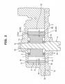
- the cover member 2 has a plate shape, as shown in Figs. 2 and 4 .
- the cover member 2 is shaped into a rectangle that extends in the up-and-down directions so as to be fitted to an outside shape of the pump body 1.
- An outer circumferential side of an inside surface 2b of the cover member 2 is fixed to a fixing surface 1g, on an opening side of the pump accommodation chamber 3, of the pump body 1 with a plurality of bolts (not shown) .
- the cover member 2 is provided, at a position corresponding to the bearing hole 1b of the pump body 1, with a bearing hole 2a that rotatably supports a large diameter other end portion 4b of the drive shaft 4.
- the cam ring 5 is formed, as a single-piece component, into a substantially cylindrical shape with so-called sintered alloy.
- the cam ring 5 has, at a predetermined position of an outer circumferential portion thereof, a substantially arc-shaped recessed grooved pivot portion 5a that is formed along an axial direction of the cam ring 5 and fitted onto the pivot pin 9.
- the cam ring 5 has, at a position opposite to this pivot portion 5a, an arm portion 5b that protrudes in the radial direction and contacts or is connected to the after-mentioned coil spring 23 as a forcing member which is set to a predetermined spring constant.
- first, second and third seal configuration portions 5c, 5d and 5e which are concentric with the respective first, second and third seal sliding contact surfaces 1d, 1e and 1f formed by an inner circumferential wall of the pump body 1, are formed at positions facing to the respective first, second and third seal sliding contact surfaces 1d, 1e and 1f so as to protrude from the outer circumferential potion of the cam ring 5.
- the first, second and third seal members 10a, 10b and 10c which are in sliding-contact with the first, second and third seal sliding contact surfaces 1d, 1e and 1f respectively upon eccentric rocking of the cam ring 5, are accommodated and held in seal holding grooves formed at seal surfaces of the seal configuration portions 5c, 5d and 5e respectively.
- the first control hydraulic chamber 21, the second control hydraulic chamber 22 and the low pressure chamber 41 are formed at right and left positions in a circumferential direction with the pivot pin 9 being a center.
- first control hydraulic chamber 21 is defined between the first seal member 10a and the third seal member 10c.
- the second control hydraulic chamber 22 is defined between the pivot pin 9 and the second seal member 10b.
- the low pressure chamber 41 is defined between the pivot pin 9 and the third seal member 10c.
- a first pressure receiving surface 5f, which faces to the first control hydraulic chamber 21, of the outer circumferential surface of the cam ring 5 is formed to be smaller due to the presence of the low pressure chamber 41 defined between the pivot pin 9 and the third seal member 10c, while a second pressure receiving surface 5g which greatly extends from the pivot pin 9 in the circumferential direction and faces to the second control hydraulic chamber 22 is formed to be larger.
- the first and second control hydraulic chambers 21 and 22 are configured so that the pump discharge pressure is introduced into the first and second control hydraulic chambers 21 and 22 through the control pressure introduction passage 60 that branches off from the discharge passage 18. That is, the first control hydraulic chamber 21 is supplied with the pump discharge pressure through a first introduction passage 61 that is one side of a bifurcated passage further branching off from the control pressure introduction passage 60. On the other hand, the second control hydraulic chamber 22 is supplied with the pump discharge pressure from a second introduction passage 62 that is the other side of the bifurcated passage through the electromagnetic switching valve 50 and the pilot valve 30. These hydraulic pressures act on the first and second pressure receiving surface 5f and 5g of the cam ring 5 which face to the first and second control hydraulic chambers 21 and 22 respectively, then a moving force (a rocking force) is given to the cam ring 5.
- the low pressure chamber 41 is formed along the up-and-down directions of the pump body 1 by the hollow groove 40, as shown in Figs. 1 to 3 .
- the low pressure chamber 41 opens to the atmospheric air outside the pump and also communicates with the oil pan 43 through a communication hole 42 formed at the cover member 2 so as to penetrate the cover member 2. That is, as described later, oil leaking out from sliding contact surfaces (side clearances) between both axial direction end surfaces 5h and 5i of the cam ring 5, the pump body 1 and the cover member 2 and so-called contaminant getting into the oil flow into the low pressure chamber 41 by the pumping operation.
- the low pressure chamber 41 is configured to discharge these oil and contaminant to the oil pan 43 through the communication hole 42.
- gaps or boundaries between the first and second control hydraulic chambers 21 and 22 and each pump chamber 13 are sealed by so-called side clearances formed between a bottom surface 3a, which is in sliding-contact with the axial direction end surface 5i of the cam ring 5, of an inside surface of the pump accommodation chamber 3 at the pump body 1 side and this axial direction end surface 5i of the cam ring 5 and between the inside surface 2b, which is in sliding-contact with the axial direction end surface 5h of the cam ring 5, of the cover member 2 and this axial direction end surface 5h of the cam ring 5.
- Gaps or boundaries between the low pressure chamber 41 and each pump chamber 13 are also sealed by the side clearances between the both axial direction end surfaces 5h and 5i of the cam ring 5, the bottom surface 3a of the pump accommodation chamber 3 and the inside surface 2b of the cover member 2.
- a section, which seals the gaps or the boundaries between the first control hydraulic chamber 21 and each pump chamber 13, of the both axial direction end surfaces 5h and 5i of the cam ring 5 which form the side clearances is called a first seal surface 44 as a first seal part.
- a section, which seals the gaps or the boundaries between the second control hydraulic chamber 22 and each pump chamber 13, of the both axial direction end surfaces 5h and 5i of the cam ring 5 is called a second seal surface 45 as a second seal part.
- the second and third second seal surfaces 45 and 46 are formed so that a width W2 in the radial direction of the second seal surface 45 and a width W2 in the radial direction of the third seal surface 46 are substantially the same as each other. Further, this radial direction width W2 is greater than a radial direction width W1 of the first seal surface 44.
- the pump chambers 13 at the first control hydraulic chamber 21 side are located in the inlet-side area with which the inlet ports 11a and 11a' communicate, and the pump chambers 13 in this inlet-side area are in a negative pressure (lowpressure) state. Because of this, a hydraulic pressure acting on the first seal surface 44 is a low pressure.
- the pump chambers 13 at the second control hydraulic chamber 22 side and the low pressure chamber 41 side are located in the outlet-side area (from the start end S up to the termination end F of the outlet ports 12a and 12a') with which the outlet ports 12a and 12a' communicate, and the pump chambers 13 in this outlet-side area are in a positive pressure (high pressure) state. Because of this, a hydraulic pressure acting on the second seal surface 45 and the third seal surface 46 is a high pressure.
- each of seal areas of the second and third second seal surfaces 45 and 46 which are formed by a relative connection with the bottom surface 3a of the pump accommodation chamber 3, is larger than a seal area of the first seal surface 44.
- an average radial direction width W1 of the first seal surface 44 is set to about 3.5 mm, whereas an average radial direction width W2 of the second and third second seal surfaces 45 and 46 is set to about 5.0 mm that is greater than the average radial direction width W1.
- the pilot valve 30 is provided at an upper end portion located in a longitudinal direction of the cover member 2 of the pump body 1 as an overlap portion with the cover member 2, and is arranged along a transverse direction.
- Thepilot valve 30 is formedmainly by a cylindrical valve body 31 that extends to an outer side of the cover member 2, a plug 32 that closes a bottom opening of the valve body 31, a spool valve body 33 that is slidably accommodated in a valve accommodation hole 31a formed in the valve body 31 along an axial direction of the valve body 31 and controls supply and discharge of the hydraulic pressure to and from the second control hydraulic chamber 22 by a pair of first and second land portions 33a and 33b that are in sliding-contact with an inner circumferential surface of the valve body 31, and a valve spring 34 that is elastically installed between the plug 32 and the spool valve body 33 at other end side inner circumferential side of the valve body 31 with a predetermined set load given to the valve spring 34 and always forces the spool valve body 33 to one end side of the valve body 31.
- An introduction port 63 that is connected to the solenoid valve 50 through a passage (hereinafter, called a downstream side passage) 62a located at a downstream side of the second introduction passage 62 opens at one end portion of the valve body 31. Further, inside the valve body 31 and the pump body 1, a passage is formed at an axial direction middle position between the valve body 31 and the pump body 1, and its one end side is connected to the second control hydraulic chamber 22, and its other end side is always connected to an after-mentioned intermediate chamber 31b. With this, a supply/discharge port 64 that supplies and discharges the hydraulic pressure to and from the second control hydraulic chamber 22 is formed.
- a communication oil passage 67 that communicates with the valve body 31 in a state in which the spool valve body 33 is positioned at a left end side position in Fig. 1 in cooperation with the pump body 1 is formed at the peripheral wall of the valve body 31.
- the spool valve body 33 is positioned at the one end side of the valve accommodation hole 31a by an urging force of the valve spring 34 (see Fig. 1 ) .
- the communication oil passage 67 communicates with the intermediate chamber 31b and the intermediate chamber 31b communicates with the second control hydraulic chamber 22 through the supply/discharge port 64, whereas communication between the first drain port 65 and the intermediate chamber 31b is interrupted by the second land portion 33b.
- the hydraulic pressure introduced from the downstream side passage 62a through the communication oil passage 67 is supplied to the second control hydraulic chamber 22 through the intermediate chamber 31b and the supply/discharge port 64.
- the solenoid valve 50 is accommodated in a valve accommodation hole (not shown) that is formed at some midpoint of the control pressure introduction passage 60.
- the solenoid valve 50 is formed mainly by a cylindrical valve body 51 having therein an oil passage 54 formed along an axial direction of the cylindrical valve body 51, a seat member 52 fixed to a top end side inner portion of the oil passage 54 and having an introduction port 55 that is connected to an upstream side of the second introduction passage 62, a ball valve body 53 provided so as to be able to be seated on and separate from a valve seat that is formed at an inner end opening edge of the seat member 52 and serving to open and close the introduction port 55, and a solenoid 56 provided at other end portion of the valve body 51.
- the valve body 51 also has, at an inner end opening edge of a valve body accommodation port 57 that accommodates therein the ball valve body 53, the same valve seat as the valve seat of the seat member 52. Further, the valve body 51 has, at an outer peripheral portion of the valve body accommodation port 57 on one end side of a peripheral wall thereof, a supply/discharge port 58 that is formed in a radial direction and is connected to the downstream side passage 62a for supplying and discharging the hydraulic pressure to and from the pilot valve 30. In addition, the valve body 51 has, at an outer peripheral portion of the oil passage 54 on the other end side of the peripheral wall thereof, a drain port 59 that is formed along the radial direction and communicates with the oil pan 43.
- the solenoid 56 is fed with an exciting current from a vehicle-mounted ECU (not shown) in accordance with an engine operating condition detected or calculated by an oil temperature and a water temperature of the internal combustion engine and a predetermined parameter such as an engine rotation speed.
- P1 in the drawing denotes an engine required pressure that corresponds to a required pressure for the VTC that is capable of improving fuel efficiency.
- P2 denotes an engine required pressure that corresponds to a required pressure for an oil jet for cooling a piston and an engine required pressure for lubrication of bearing parts of the crankshaft at a time when the engine rotation speed is high.
- a connecting line formed by connecting these points P1 and P2 by a solid line denotes an ideal necessary pressure (a discharge pressure) P according to the engine rotation speed.
- Fig. 7 shows a second embodiment.
- arrangement of the oil pump is reversed with respect to the first embodiment, and the rotation direction of the drive shaft 4 is a counterclockwise direction (in an arrow direction) in the drawing. Further, the low pressure chamber 41 in the first embodiment is removed. Since a basic structure or configuration of the second embodiment is the same as that of the first embodiment, the same element or component as that of the first embodiment is denoted by the same reference sign, and its explanation will be omitted.
- the present invention is not limited to the above embodiments.
- the outlet-side area unlike the above embodiments, it could be formed from a termination end F of the outlet port 12a up to a start end S' of the inlet port 11a in the rotation direction of the rotor 6.
- a vane pump is used as the oil pump.
- a gear pump could be used as the oil pump.
- a minimum radial direction width of the second seal part is greater than a minimum radial direction width of the first seal part.
- a maximum radial direction width of the second seal part is greater than a maximum radial direction width of the first seal part.
- the inlet section and the outlet section are each formed into an arc shape along a moving direction of the movable member.
- the outlet-side area is formed at an area from a termination end of the inlet section to a termination end of the outlet section in a rotation direction of the rotor.
- a radial direction width of the second seal part that seals a gap between each working fluid chamber and the second control hydraulic chamber at the outlet-side area is greater than the radial direction width of the first seal part.
- variable displacement pump further comprises a third control hydraulic chamber that is formed between the rocking fulcrum of the movable member and the first control hydraulic chamber and communicates with a low pressure side. And, a radial direction width of a third seal part that is formed on the both end surfaces of the movable member and seals a gap between each working fluid chamber and the third control hydraulic chamber in the outlet-side area is greater than the radial direction width of the first seal part.
- the outlet-side area is formed at an area from a termination end of the outlet section to a start end of the inlet section in a rotation direction of the rotor.
- the outlet-side area is formed at an area from a termination end of the inlet section to a start end of the outlet section in a rotation direction of the rotor.
Landscapes
- Engineering & Computer Science (AREA)
- Mechanical Engineering (AREA)
- General Engineering & Computer Science (AREA)
- Details And Applications Of Rotary Liquid Pumps (AREA)
- Rotary Pumps (AREA)
Claims (13)
- Eine Pump emit variable Verdrängung umfassend:einen Rotor (6), der angetrieben wird und sich dreht;eine Vielzahl von Schaufeln (7), die an einem äußeren Umfangsabschnitt des Rotors (6) so angeordnet sind, dass sie aus- und eingefahren werden können;ein ringförmiges bewegliches Element (5), das eine Vielzahl von Arbeitsfluidkammern (13) definiert, indem es den Rotor (6) und die Vielzahl von Schaufeln (7) an einer inneren Umfangsseite des beweglichen Elements (5) aufnimmt und eine Volumenänderung jeder Arbeitsfluidkammer (13) während der Drehung des Rotors (6) durch eine Bewegung ändert, so dass sich eine innere Umfangsmitte des beweglichen Elements (5) in Bezug auf eine Drehmitte des Rotors (6) ändert;ein Pumpengehäuse, in dem der Rotor (6), die Schaufeln (7) und das bewegliche Element (5) untergebracht sind, wobei beide in axialer Richtung verlaufenden Endflächen (5h, 5i) des beweglichen Elements (5) in Gleitkontakt mit den beiden gegenüberliegenden Innenflächen des Pumpengehäuses stehen;einen Einlassabschnitt (11a, 11a'), der an mindestens einer der beiden Innenflächen des Pumpengehäuses ausgebildet ist und sich in einem einlassseitigen Bereich öffnet, in dem ein Volumen jeder Arbeitsfluidkammer (13) durch die Drehung des Rotors (6) vergrößert wird;einen Auslassabschnitt (12a, 12a'), der an mindestens einer der beiden Innenflächen des Pumpengehäuses ausgebildet ist und in einem auslassseitigen Bereich mündet, in dem das Volumen jeder Arbeitsfluidkammer (13) durch die Drehung des Rotors (6) verringert wird;eine erste Steuerhydraulikkammer (21), die durch ihren Innendruck, der dadurch erzeugt wird, dass ihr ein vom Auslassabschnitt (12a, 12a') abgegebener Auslassdruck zugeführt wird, eine Kraft auf das bewegliche Element (5) in einer Richtung ausübt, in der die Volumenänderung jeder Arbeitsfluidkammer (13) verringert wird;eine zweite Steuerhydraulikkammer (22), die durch Zufuhr und Ablassen des Ablassdrucks und Unterbrechung der Zufuhr des Ablassdrucks, die selektiv durch einen Schaltmechanismus (50) geschaltet werden, eine Kraft auf das bewegliche Element (5) in einer Richtung ausübt, in der die Volumenänderung jeder Arbeitsfluidkammer (13) vergrößert wird;ein erstes Dichtungsteil (44), das an den beiden Endflächen (5h, 5i) des beweglichen Elements (5) ausgebildet ist, die in Gleitkontakt mit den beiden Innenflächen des Pumpengehäuses stehen, und einen Spalt zwischen jeder Arbeitsfluidkammer (13) und der ersten Steuerhydraulikkammer (21) abdichtet; undein zweites Dichtungsteil (45), das an den beiden Endflächen (5h, 5i) des beweglichen Elements (5) ausgebildet ist und einen Spalt zwischen jeder Arbeitsfluidkammer (13) und der zweiten Steuerhydraulikkammer (22) im auslassseitigen Bereich abdichtet,gekennzeichnet dadurch, dasseine Breite in radialer Richtung (W2) des zweiten Dichtungsteils (45) über den gesamten auslassseitigen Bereich, mit Ausnahme einer Umgebung eines Drehpunktabschnitts (5a) und einer Umgebung eines Dichtungselements (10b), die das zweite Dichtungsteil (45) definieren, größer ist als eine Breite in radialer Richtung (W1) des ersten Dichtungsteils (44).
- Die Pumpe mit variabler Verdrängung gemäß Anspruch 1, wobei:
eine mittlere Breite (W2) des zweiten Dichtungsteils (45) in radialer Richtung größer ist als eine mittlere Breite (W1) des ersten Dichtungsteils (44) in radialer Richtung. - Die Pumpe mit variabler Verdrängung gemäß Anspruch 1, wobei:
eine minimale Breite in radialer Richtung (W2) des zweiten Dichtungsteils (45) größer ist als eine minimale Breite in radialer Richtung (W1) des ersten Dichtungsteils (44). - Die Pumpe mit variabler Verdrängung gemäß Anspruch 1, wobei:
eine maximale Breite in radialer Richtung (W2) des zweiten Dichtungsteils (45) größer ist als eine maximale Breite in radialer Richtung (W1) des ersten Dichtungsteils (44). - Die Pumpe mit variabler Verdrängung gemäß Anspruch 1, wobei:
der auslassseitige Bereich in einem Bereich von einem Abschlussende (F') des Einlassabschnitts (11a) zu einem Abschlussende (F) des Auslassabschnitts (12a) in einer Drehrichtung des Rotors (6) gebildet ist. - Die Pumpe mit variabler Verdrängung gemäß Anspruch 1, wobei:
der auslassseitige Bereich in einem Bereich von einem Anfangsende (S) zu einem Abschlussende (F) des Auslassabschnitts (12a) in einer Drehrichtung des Rotors (6) gebildet ist. - Die Pumpe mit variabler Verdrängung gemäß Anspruch 1, wobei:
der auslassseitige Bereich in einem Bereich von einem Abschlussende (F) des Auslassabschnitts (12a) zu einem Anfangsende (S') des Einlassabschnitts (11a) in einer Drehrichtung des Rotors (6) gebildet ist. - Die Pumpe mit variabler Verdrängung gemäß Anspruch 1, wobei:
der auslassseitige Bereich in einem Bereich von einem Abschlussende (F') des Einlassabschnitts (11a) zu einem Anfangsende (S) des Auslassabschnitts (12a) in einer Drehrichtung des Rotors (6) gebildet ist. - Die Pumpe mit variabler Verdrängung gemäß Anspruch 1, wobei:
das bewegliche Element (5) ein Nockenring (5) ist, der die Volumenänderung jeder Arbeitsfluidkammer (13) durch Kippen auf einem Kippdrehpunkt (9) vergrößert und verkleinert. - Die Pumpe mit variabler Verdrängung gemäß Anspruch 9, die ferner umfasst:eine dritte Steuerhydraulikkammer (41), die zwischen dem Kippdrehpunkt (9) des beweglichen Elements (5) und der ersten Steuerhydraulikkammer (21) ausgebildet ist und mit einer Niederdruckseite in Verbindung steht, und wobeieine Breite in radialer Richtung (W2) eines dritten Dichtungsteils (46), das an den beiden Endflächen (5h, 5i) des beweglichen Elements (5) ausgebildet ist und einen Spalt zwischen jeder Arbeitsfluidkammer (13) und der dritten Steuerhydraulikkammer (41) im auslassseitigen Bereich abdichtet, größer ist als die Breite in radialer Richtung (W1) des ersten Dichtungsteils (44).
- Die Pumpe mit variabler Verdrängung gemäß Anspruch 1, wobei:
die Breite (W2) des zweiten Dichtungsteils (45) in radialer Richtung 3,5 mm oder mehr beträgt. - Die Pumpe mit variabler Verdrängung gemäß Anspruch 1, ferner umfassend:
einen Steuermechanismus (30), der die Zufuhr und den Abfluss eines hydraulischen Drucks zu und von der zweiten Steuerhydraulikkammer (22) in Abhängigkeit von einem Abflussdruck des Arbeitsfluids aus dem Auslassabschnitt (12a, 12a') steuert. - Die Pumpe mit variabler Verdrängung gemäß Anspruch 1, wobei:
eine Fläche einer Druckaufnahmefläche (5g) auf der Seite der zweiten Steuerhydraulikkammer (22) des beweglichen Elements (5) größer ist als eine Fläche einer Druckaufnahmefläche (5f) auf der Seite der ersten Steuerhydraulikkammer (21) des beweglichen Elements (5).
Applications Claiming Priority (2)
| Application Number | Priority Date | Filing Date | Title |
|---|---|---|---|
| JP2016042943 | 2016-03-07 | ||
| PCT/JP2017/004185 WO2017154438A1 (ja) | 2016-03-07 | 2017-02-06 | 可変容量形ポンプ |
Publications (3)
| Publication Number | Publication Date |
|---|---|
| EP3428450A1 EP3428450A1 (de) | 2019-01-16 |
| EP3428450A4 EP3428450A4 (de) | 2019-01-16 |
| EP3428450B1 true EP3428450B1 (de) | 2023-12-27 |
Family
ID=59790254
Family Applications (1)
| Application Number | Title | Priority Date | Filing Date |
|---|---|---|---|
| EP17762782.5A Active EP3428450B1 (de) | 2016-03-07 | 2017-02-06 | Pumpe mit variabler verdrängung |
Country Status (5)
| Country | Link |
|---|---|
| US (1) | US11168684B2 (de) |
| EP (1) | EP3428450B1 (de) |
| JP (1) | JP6664465B2 (de) |
| CN (1) | CN108779772B (de) |
| WO (1) | WO2017154438A1 (de) |
Families Citing this family (6)
| Publication number | Priority date | Publication date | Assignee | Title |
|---|---|---|---|---|
| JP7324158B2 (ja) * | 2020-02-07 | 2023-08-09 | 日立Astemo株式会社 | 可変容量形ポンプ |
| JP7437209B2 (ja) * | 2020-03-26 | 2024-02-22 | カヤバ株式会社 | ポンプ制御圧レギュレータ |
| CN112228760A (zh) * | 2020-11-20 | 2021-01-15 | 湖南机油泵股份有限公司 | 一种结构简化的可变排量转子泵 |
| US11635076B2 (en) * | 2021-01-22 | 2023-04-25 | Slw Automotive Inc. | Variable displacement vane pump with improved pressure control and range |
| CN114110398B (zh) * | 2021-11-30 | 2023-03-24 | 湖南机油泵股份有限公司 | 一种能减小压力波动的变量机油泵 |
| CN118489034A (zh) * | 2022-01-31 | 2024-08-13 | 日立安斯泰莫株式会社 | 液压控制阀的控制装置 |
Family Cites Families (9)
| Publication number | Priority date | Publication date | Assignee | Title |
|---|---|---|---|---|
| JPH10205461A (ja) * | 1997-01-20 | 1998-08-04 | Nachi Fujikoshi Corp | 可変吐出量ベーンポンプ |
| JP3776601B2 (ja) * | 1998-09-28 | 2006-05-17 | カヤバ工業株式会社 | 可変容量型ベーンポンプ |
| JP5313997B2 (ja) * | 2010-12-08 | 2013-10-09 | 日立オートモティブシステムズ株式会社 | 可変容量型ベーンポンプ |
| JP5690238B2 (ja) * | 2011-07-26 | 2015-03-25 | 日立オートモティブシステムズ株式会社 | 可変容量形オイルポンプ |
| DE112013004386T5 (de) * | 2012-09-07 | 2015-06-11 | Hitachi Automotive Systems, Ltd. | Ölpumpe mit einer variablen Kapazität und diese verwendendes Ölzuführsystem |
| JP6006098B2 (ja) | 2012-11-27 | 2016-10-12 | 日立オートモティブシステムズ株式会社 | 可変容量形ポンプ |
| CA2902472C (en) * | 2013-03-13 | 2018-10-02 | Magna Powertrain Inc. | Vane pump with multiple control chambers |
| JP6289943B2 (ja) | 2014-03-10 | 2018-03-07 | 日立オートモティブシステムズ株式会社 | 可変容量形ポンプ |
| JP2016104967A (ja) * | 2014-12-01 | 2016-06-09 | 日立オートモティブシステムズ株式会社 | 可変容量形オイルポンプ |
-
2017
- 2017-02-06 US US16/082,242 patent/US11168684B2/en active Active
- 2017-02-06 EP EP17762782.5A patent/EP3428450B1/de active Active
- 2017-02-06 CN CN201780015131.9A patent/CN108779772B/zh active Active
- 2017-02-06 JP JP2018504058A patent/JP6664465B2/ja active Active
- 2017-02-06 WO PCT/JP2017/004185 patent/WO2017154438A1/ja not_active Ceased
Also Published As
| Publication number | Publication date |
|---|---|
| JPWO2017154438A1 (ja) | 2019-01-10 |
| EP3428450A1 (de) | 2019-01-16 |
| US11168684B2 (en) | 2021-11-09 |
| EP3428450A4 (de) | 2019-01-16 |
| CN108779772A (zh) | 2018-11-09 |
| JP6664465B2 (ja) | 2020-03-13 |
| WO2017154438A1 (ja) | 2017-09-14 |
| US20200032793A1 (en) | 2020-01-30 |
| CN108779772B (zh) | 2020-09-08 |
Similar Documents
| Publication | Publication Date | Title |
|---|---|---|
| EP3428450B1 (de) | Pumpe mit variabler verdrängung | |
| US9670926B2 (en) | Variable displacement pump | |
| US10060433B2 (en) | Variable vane displacement pump utilizing a control valve and a switching valve | |
| US9243632B2 (en) | Variable displacement oil pump | |
| JP5620882B2 (ja) | 可変容量形ポンプ | |
| JP6838772B2 (ja) | 可変容量形オイルポンプ | |
| CN107208632A (zh) | 可变容量型泵 | |
| JP6039831B2 (ja) | 可変容量形ポンプ | |
| CN109642568B (zh) | 可变容量泵以及内燃机的工作油供给系统 | |
| CN108026923B (zh) | 容量可变型油泵 | |
| US12448967B2 (en) | Variable displacement oil pump | |
| JP6573509B2 (ja) | 可変容量形ポンプ | |
| US12297829B2 (en) | Variable-capacity oil pump | |
| WO2020195077A1 (ja) | 可変容量形ポンプ | |
| JP7522861B2 (ja) | 可変容量形ポンプ | |
| JP6543682B2 (ja) | 可変容量形ポンプ | |
| JP2015083839A (ja) | 可変容量形ポンプ | |
| JP2020041522A (ja) | 可変容量形ポンプ |
Legal Events
| Date | Code | Title | Description |
|---|---|---|---|
| STAA | Information on the status of an ep patent application or granted ep patent |
Free format text: STATUS: THE INTERNATIONAL PUBLICATION HAS BEEN MADE |
|
| PUAI | Public reference made under article 153(3) epc to a published international application that has entered the european phase |
Free format text: ORIGINAL CODE: 0009012 |
|
| STAA | Information on the status of an ep patent application or granted ep patent |
Free format text: STATUS: REQUEST FOR EXAMINATION WAS MADE |
|
| 17P | Request for examination filed |
Effective date: 20180903 |
|
| A4 | Supplementary search report drawn up and despatched |
Effective date: 20181113 |
|
| AK | Designated contracting states |
Kind code of ref document: A1 Designated state(s): AL AT BE BG CH CY CZ DE DK EE ES FI FR GB GR HR HU IE IS IT LI LT LU LV MC MK MT NL NO PL PT RO RS SE SI SK SM TR |
|
| AX | Request for extension of the european patent |
Extension state: BA ME |
|
| DAV | Request for validation of the european patent (deleted) | ||
| DAX | Request for extension of the european patent (deleted) | ||
| STAA | Information on the status of an ep patent application or granted ep patent |
Free format text: STATUS: EXAMINATION IS IN PROGRESS |
|
| 17Q | First examination report despatched |
Effective date: 20211027 |
|
| RAP3 | Party data changed (applicant data changed or rights of an application transferred) |
Owner name: HITACHI ASTEMO, LTD. |
|
| GRAP | Despatch of communication of intention to grant a patent |
Free format text: ORIGINAL CODE: EPIDOSNIGR1 |
|
| STAA | Information on the status of an ep patent application or granted ep patent |
Free format text: STATUS: GRANT OF PATENT IS INTENDED |
|
| INTG | Intention to grant announced |
Effective date: 20230912 |
|
| GRAS | Grant fee paid |
Free format text: ORIGINAL CODE: EPIDOSNIGR3 |
|
| GRAA | (expected) grant |
Free format text: ORIGINAL CODE: 0009210 |
|
| STAA | Information on the status of an ep patent application or granted ep patent |
Free format text: STATUS: THE PATENT HAS BEEN GRANTED |
|
| AK | Designated contracting states |
Kind code of ref document: B1 Designated state(s): AL AT BE BG CH CY CZ DE DK EE ES FI FR GB GR HR HU IE IS IT LI LT LU LV MC MK MT NL NO PL PT RO RS SE SI SK SM TR |
|
| REG | Reference to a national code |
Ref country code: GB Ref legal event code: FG4D |
|
| REG | Reference to a national code |
Ref country code: CH Ref legal event code: EP |
|
| REG | Reference to a national code |
Ref country code: DE Ref legal event code: R096 Ref document number: 602017077922 Country of ref document: DE |
|
| REG | Reference to a national code |
Ref country code: IE Ref legal event code: FG4D |
|
| PG25 | Lapsed in a contracting state [announced via postgrant information from national office to epo] |
Ref country code: GR Free format text: LAPSE BECAUSE OF FAILURE TO SUBMIT A TRANSLATION OF THE DESCRIPTION OR TO PAY THE FEE WITHIN THE PRESCRIBED TIME-LIMIT Effective date: 20240328 |
|
| REG | Reference to a national code |
Ref country code: LT Ref legal event code: MG9D |
|
| PG25 | Lapsed in a contracting state [announced via postgrant information from national office to epo] |
Ref country code: LT Free format text: LAPSE BECAUSE OF FAILURE TO SUBMIT A TRANSLATION OF THE DESCRIPTION OR TO PAY THE FEE WITHIN THE PRESCRIBED TIME-LIMIT Effective date: 20231227 |
|
| PG25 | Lapsed in a contracting state [announced via postgrant information from national office to epo] |
Ref country code: ES Free format text: LAPSE BECAUSE OF FAILURE TO SUBMIT A TRANSLATION OF THE DESCRIPTION OR TO PAY THE FEE WITHIN THE PRESCRIBED TIME-LIMIT Effective date: 20231227 |
|
| PG25 | Lapsed in a contracting state [announced via postgrant information from national office to epo] |
Ref country code: LT Free format text: LAPSE BECAUSE OF FAILURE TO SUBMIT A TRANSLATION OF THE DESCRIPTION OR TO PAY THE FEE WITHIN THE PRESCRIBED TIME-LIMIT Effective date: 20231227 Ref country code: GR Free format text: LAPSE BECAUSE OF FAILURE TO SUBMIT A TRANSLATION OF THE DESCRIPTION OR TO PAY THE FEE WITHIN THE PRESCRIBED TIME-LIMIT Effective date: 20240328 Ref country code: FI Free format text: LAPSE BECAUSE OF FAILURE TO SUBMIT A TRANSLATION OF THE DESCRIPTION OR TO PAY THE FEE WITHIN THE PRESCRIBED TIME-LIMIT Effective date: 20231227 Ref country code: ES Free format text: LAPSE BECAUSE OF FAILURE TO SUBMIT A TRANSLATION OF THE DESCRIPTION OR TO PAY THE FEE WITHIN THE PRESCRIBED TIME-LIMIT Effective date: 20231227 Ref country code: BG Free format text: LAPSE BECAUSE OF FAILURE TO SUBMIT A TRANSLATION OF THE DESCRIPTION OR TO PAY THE FEE WITHIN THE PRESCRIBED TIME-LIMIT Effective date: 20240327 |
|
| REG | Reference to a national code |
Ref country code: NL Ref legal event code: MP Effective date: 20231227 |
|
| REG | Reference to a national code |
Ref country code: AT Ref legal event code: MK05 Ref document number: 1644757 Country of ref document: AT Kind code of ref document: T Effective date: 20231227 |
|
| PG25 | Lapsed in a contracting state [announced via postgrant information from national office to epo] |
Ref country code: NL Free format text: LAPSE BECAUSE OF FAILURE TO SUBMIT A TRANSLATION OF THE DESCRIPTION OR TO PAY THE FEE WITHIN THE PRESCRIBED TIME-LIMIT Effective date: 20231227 |
|
| PG25 | Lapsed in a contracting state [announced via postgrant information from national office to epo] |
Ref country code: SE Free format text: LAPSE BECAUSE OF FAILURE TO SUBMIT A TRANSLATION OF THE DESCRIPTION OR TO PAY THE FEE WITHIN THE PRESCRIBED TIME-LIMIT Effective date: 20231227 Ref country code: RS Free format text: LAPSE BECAUSE OF FAILURE TO SUBMIT A TRANSLATION OF THE DESCRIPTION OR TO PAY THE FEE WITHIN THE PRESCRIBED TIME-LIMIT Effective date: 20231227 Ref country code: NO Free format text: LAPSE BECAUSE OF FAILURE TO SUBMIT A TRANSLATION OF THE DESCRIPTION OR TO PAY THE FEE WITHIN THE PRESCRIBED TIME-LIMIT Effective date: 20240327 Ref country code: NL Free format text: LAPSE BECAUSE OF FAILURE TO SUBMIT A TRANSLATION OF THE DESCRIPTION OR TO PAY THE FEE WITHIN THE PRESCRIBED TIME-LIMIT Effective date: 20231227 Ref country code: LV Free format text: LAPSE BECAUSE OF FAILURE TO SUBMIT A TRANSLATION OF THE DESCRIPTION OR TO PAY THE FEE WITHIN THE PRESCRIBED TIME-LIMIT Effective date: 20231227 Ref country code: HR Free format text: LAPSE BECAUSE OF FAILURE TO SUBMIT A TRANSLATION OF THE DESCRIPTION OR TO PAY THE FEE WITHIN THE PRESCRIBED TIME-LIMIT Effective date: 20231227 |
|
| PG25 | Lapsed in a contracting state [announced via postgrant information from national office to epo] |
Ref country code: IS Free format text: LAPSE BECAUSE OF FAILURE TO SUBMIT A TRANSLATION OF THE DESCRIPTION OR TO PAY THE FEE WITHIN THE PRESCRIBED TIME-LIMIT Effective date: 20240427 |
|
| PG25 | Lapsed in a contracting state [announced via postgrant information from national office to epo] |
Ref country code: CZ Free format text: LAPSE BECAUSE OF FAILURE TO SUBMIT A TRANSLATION OF THE DESCRIPTION OR TO PAY THE FEE WITHIN THE PRESCRIBED TIME-LIMIT Effective date: 20231227 Ref country code: AT Free format text: LAPSE BECAUSE OF FAILURE TO SUBMIT A TRANSLATION OF THE DESCRIPTION OR TO PAY THE FEE WITHIN THE PRESCRIBED TIME-LIMIT Effective date: 20231227 |
|
| PG25 | Lapsed in a contracting state [announced via postgrant information from national office to epo] |
Ref country code: SK Free format text: LAPSE BECAUSE OF FAILURE TO SUBMIT A TRANSLATION OF THE DESCRIPTION OR TO PAY THE FEE WITHIN THE PRESCRIBED TIME-LIMIT Effective date: 20231227 |
|
| PG25 | Lapsed in a contracting state [announced via postgrant information from national office to epo] |
Ref country code: SM Free format text: LAPSE BECAUSE OF FAILURE TO SUBMIT A TRANSLATION OF THE DESCRIPTION OR TO PAY THE FEE WITHIN THE PRESCRIBED TIME-LIMIT Effective date: 20231227 Ref country code: SK Free format text: LAPSE BECAUSE OF FAILURE TO SUBMIT A TRANSLATION OF THE DESCRIPTION OR TO PAY THE FEE WITHIN THE PRESCRIBED TIME-LIMIT Effective date: 20231227 Ref country code: RO Free format text: LAPSE BECAUSE OF FAILURE TO SUBMIT A TRANSLATION OF THE DESCRIPTION OR TO PAY THE FEE WITHIN THE PRESCRIBED TIME-LIMIT Effective date: 20231227 Ref country code: IT Free format text: LAPSE BECAUSE OF FAILURE TO SUBMIT A TRANSLATION OF THE DESCRIPTION OR TO PAY THE FEE WITHIN THE PRESCRIBED TIME-LIMIT Effective date: 20231227 Ref country code: IS Free format text: LAPSE BECAUSE OF FAILURE TO SUBMIT A TRANSLATION OF THE DESCRIPTION OR TO PAY THE FEE WITHIN THE PRESCRIBED TIME-LIMIT Effective date: 20240427 Ref country code: EE Free format text: LAPSE BECAUSE OF FAILURE TO SUBMIT A TRANSLATION OF THE DESCRIPTION OR TO PAY THE FEE WITHIN THE PRESCRIBED TIME-LIMIT Effective date: 20231227 Ref country code: CZ Free format text: LAPSE BECAUSE OF FAILURE TO SUBMIT A TRANSLATION OF THE DESCRIPTION OR TO PAY THE FEE WITHIN THE PRESCRIBED TIME-LIMIT Effective date: 20231227 Ref country code: AT Free format text: LAPSE BECAUSE OF FAILURE TO SUBMIT A TRANSLATION OF THE DESCRIPTION OR TO PAY THE FEE WITHIN THE PRESCRIBED TIME-LIMIT Effective date: 20231227 |
|
| PG25 | Lapsed in a contracting state [announced via postgrant information from national office to epo] |
Ref country code: PL Free format text: LAPSE BECAUSE OF FAILURE TO SUBMIT A TRANSLATION OF THE DESCRIPTION OR TO PAY THE FEE WITHIN THE PRESCRIBED TIME-LIMIT Effective date: 20231227 Ref country code: PT Free format text: LAPSE BECAUSE OF FAILURE TO SUBMIT A TRANSLATION OF THE DESCRIPTION OR TO PAY THE FEE WITHIN THE PRESCRIBED TIME-LIMIT Effective date: 20240429 |
|
| PG25 | Lapsed in a contracting state [announced via postgrant information from national office to epo] |
Ref country code: PT Free format text: LAPSE BECAUSE OF FAILURE TO SUBMIT A TRANSLATION OF THE DESCRIPTION OR TO PAY THE FEE WITHIN THE PRESCRIBED TIME-LIMIT Effective date: 20240429 Ref country code: PL Free format text: LAPSE BECAUSE OF FAILURE TO SUBMIT A TRANSLATION OF THE DESCRIPTION OR TO PAY THE FEE WITHIN THE PRESCRIBED TIME-LIMIT Effective date: 20231227 |
|
| PG25 | Lapsed in a contracting state [announced via postgrant information from national office to epo] |
Ref country code: MC Free format text: LAPSE BECAUSE OF FAILURE TO SUBMIT A TRANSLATION OF THE DESCRIPTION OR TO PAY THE FEE WITHIN THE PRESCRIBED TIME-LIMIT Effective date: 20231227 |
|
| REG | Reference to a national code |
Ref country code: DE Ref legal event code: R097 Ref document number: 602017077922 Country of ref document: DE Ref country code: CH Ref legal event code: PL |
|
| PG25 | Lapsed in a contracting state [announced via postgrant information from national office to epo] |
Ref country code: DK Free format text: LAPSE BECAUSE OF FAILURE TO SUBMIT A TRANSLATION OF THE DESCRIPTION OR TO PAY THE FEE WITHIN THE PRESCRIBED TIME-LIMIT Effective date: 20231227 |
|
| PG25 | Lapsed in a contracting state [announced via postgrant information from national office to epo] |
Ref country code: LU Free format text: LAPSE BECAUSE OF NON-PAYMENT OF DUE FEES Effective date: 20240206 |
|
| PG25 | Lapsed in a contracting state [announced via postgrant information from national office to epo] |
Ref country code: CH Free format text: LAPSE BECAUSE OF NON-PAYMENT OF DUE FEES Effective date: 20240229 |
|
| PG25 | Lapsed in a contracting state [announced via postgrant information from national office to epo] |
Ref country code: LU Free format text: LAPSE BECAUSE OF NON-PAYMENT OF DUE FEES Effective date: 20240206 Ref country code: DK Free format text: LAPSE BECAUSE OF FAILURE TO SUBMIT A TRANSLATION OF THE DESCRIPTION OR TO PAY THE FEE WITHIN THE PRESCRIBED TIME-LIMIT Effective date: 20231227 Ref country code: CH Free format text: LAPSE BECAUSE OF NON-PAYMENT OF DUE FEES Effective date: 20240229 |
|
| PLBE | No opposition filed within time limit |
Free format text: ORIGINAL CODE: 0009261 |
|
| STAA | Information on the status of an ep patent application or granted ep patent |
Free format text: STATUS: NO OPPOSITION FILED WITHIN TIME LIMIT |
|
| GBPC | Gb: european patent ceased through non-payment of renewal fee |
Effective date: 20240327 |
|
| 26N | No opposition filed |
Effective date: 20240930 |
|
| REG | Reference to a national code |
Ref country code: BE Ref legal event code: MM Effective date: 20240229 |
|
| PG25 | Lapsed in a contracting state [announced via postgrant information from national office to epo] |
Ref country code: BE Free format text: LAPSE BECAUSE OF NON-PAYMENT OF DUE FEES Effective date: 20240229 |
|
| PG25 | Lapsed in a contracting state [announced via postgrant information from national office to epo] |
Ref country code: GB Free format text: LAPSE BECAUSE OF NON-PAYMENT OF DUE FEES Effective date: 20240327 |
|
| PG25 | Lapsed in a contracting state [announced via postgrant information from national office to epo] |
Ref country code: IE Free format text: LAPSE BECAUSE OF NON-PAYMENT OF DUE FEES Effective date: 20240206 |
|
| PG25 | Lapsed in a contracting state [announced via postgrant information from national office to epo] |
Ref country code: IE Free format text: LAPSE BECAUSE OF NON-PAYMENT OF DUE FEES Effective date: 20240206 Ref country code: GB Free format text: LAPSE BECAUSE OF NON-PAYMENT OF DUE FEES Effective date: 20240327 Ref country code: BE Free format text: LAPSE BECAUSE OF NON-PAYMENT OF DUE FEES Effective date: 20240229 |
|
| PG25 | Lapsed in a contracting state [announced via postgrant information from national office to epo] |
Ref country code: SI Free format text: LAPSE BECAUSE OF FAILURE TO SUBMIT A TRANSLATION OF THE DESCRIPTION OR TO PAY THE FEE WITHIN THE PRESCRIBED TIME-LIMIT Effective date: 20231227 |
|
| PG25 | Lapsed in a contracting state [announced via postgrant information from national office to epo] |
Ref country code: CY Free format text: LAPSE BECAUSE OF FAILURE TO SUBMIT A TRANSLATION OF THE DESCRIPTION OR TO PAY THE FEE WITHIN THE PRESCRIBED TIME-LIMIT; INVALID AB INITIO Effective date: 20170206 |
|
| PG25 | Lapsed in a contracting state [announced via postgrant information from national office to epo] |
Ref country code: HU Free format text: LAPSE BECAUSE OF FAILURE TO SUBMIT A TRANSLATION OF THE DESCRIPTION OR TO PAY THE FEE WITHIN THE PRESCRIBED TIME-LIMIT; INVALID AB INITIO Effective date: 20170206 |
|
| PG25 | Lapsed in a contracting state [announced via postgrant information from national office to epo] |
Ref country code: TR Free format text: LAPSE BECAUSE OF FAILURE TO SUBMIT A TRANSLATION OF THE DESCRIPTION OR TO PAY THE FEE WITHIN THE PRESCRIBED TIME-LIMIT Effective date: 20231227 |
|
| PGFP | Annual fee paid to national office [announced via postgrant information from national office to epo] |
Ref country code: FR Payment date: 20251231 Year of fee payment: 10 |
|
| PGFP | Annual fee paid to national office [announced via postgrant information from national office to epo] |
Ref country code: DE Payment date: 20251230 Year of fee payment: 10 |