EP3428492A1 - Bouchon d'étanchéité - Google Patents
Bouchon d'étanchéité Download PDFInfo
- Publication number
- EP3428492A1 EP3428492A1 EP17180749.8A EP17180749A EP3428492A1 EP 3428492 A1 EP3428492 A1 EP 3428492A1 EP 17180749 A EP17180749 A EP 17180749A EP 3428492 A1 EP3428492 A1 EP 3428492A1
- Authority
- EP
- European Patent Office
- Prior art keywords
- cap
- sealing
- cylindrical
- section
- opening
- Prior art date
- Legal status (The legal status is an assumption and is not a legal conclusion. Google has not performed a legal analysis and makes no representation as to the accuracy of the status listed.)
- Granted
Links
Images
Classifications
-
- F—MECHANICAL ENGINEERING; LIGHTING; HEATING; WEAPONS; BLASTING
- F16—ENGINEERING ELEMENTS AND UNITS; GENERAL MEASURES FOR PRODUCING AND MAINTAINING EFFECTIVE FUNCTIONING OF MACHINES OR INSTALLATIONS; THERMAL INSULATION IN GENERAL
- F16K—VALVES; TAPS; COCKS; ACTUATING-FLOATS; DEVICES FOR VENTING OR AERATING
- F16K17/00—Safety valves; Equalising valves, e.g. pressure relief valves
- F16K17/02—Safety valves; Equalising valves, e.g. pressure relief valves opening on surplus pressure on one side; closing on insufficient pressure on one side
- F16K17/04—Safety valves; Equalising valves, e.g. pressure relief valves opening on surplus pressure on one side; closing on insufficient pressure on one side spring-loaded
-
- B—PERFORMING OPERATIONS; TRANSPORTING
- B33—ADDITIVE MANUFACTURING TECHNOLOGY
- B33Y—ADDITIVE MANUFACTURING, i.e. MANUFACTURING OF THREE-DIMENSIONAL [3D] OBJECTS BY ADDITIVE DEPOSITION, ADDITIVE AGGLOMERATION OR ADDITIVE LAYERING, e.g. BY 3D PRINTING, STEREOLITHOGRAPHY OR SELECTIVE LASER SINTERING
- B33Y80/00—Products made by additive manufacturing
-
- F—MECHANICAL ENGINEERING; LIGHTING; HEATING; WEAPONS; BLASTING
- F16—ENGINEERING ELEMENTS AND UNITS; GENERAL MEASURES FOR PRODUCING AND MAINTAINING EFFECTIVE FUNCTIONING OF MACHINES OR INSTALLATIONS; THERMAL INSULATION IN GENERAL
- F16J—PISTONS; CYLINDERS; SEALINGS
- F16J13/00—Covers or similar closure members for pressure vessels in general
- F16J13/24—Covers or similar closure members for pressure vessels in general with safety devices, e.g. to prevent opening prior to pressure release
-
- F—MECHANICAL ENGINEERING; LIGHTING; HEATING; WEAPONS; BLASTING
- F16—ENGINEERING ELEMENTS AND UNITS; GENERAL MEASURES FOR PRODUCING AND MAINTAINING EFFECTIVE FUNCTIONING OF MACHINES OR INSTALLATIONS; THERMAL INSULATION IN GENERAL
- F16K—VALVES; TAPS; COCKS; ACTUATING-FLOATS; DEVICES FOR VENTING OR AERATING
- F16K17/00—Safety valves; Equalising valves, e.g. pressure relief valves
- F16K17/02—Safety valves; Equalising valves, e.g. pressure relief valves opening on surplus pressure on one side; closing on insufficient pressure on one side
- F16K17/14—Safety valves; Equalising valves, e.g. pressure relief valves opening on surplus pressure on one side; closing on insufficient pressure on one side with fracturing member
Definitions
- the present invention relates generally to a sealing cap and particularly to a sealing cap for subsea devices.
- Safety and reliability are two key design parameters of any product or system. While for some applications safety requirements play a less important role, for example because the product or system in itself is non-hazardous, does not contain hazardous materials and is used exclusively in a non-hazardous environment, most products or systems need to be designed carefully so as to not create unnecessary risk for their operators or any third party, or the environment. Likewise, a limited reliability may be acceptable for some products and systems, for example products or systems that have short renewal cycles such as consumer electronics, whereas for other applications a high reliability is required. In most cases increasing safety and reliability of a product or system will lead to increased cost, and while it is typically out of the question to not implement a safety measure for its cost the same is not necessarily true for reliability.
- One class of subsea devices will be filled with oil at the end of the production process thereby providing inner hull stability to the subsea device by the incompressible oil when the subsea device is subjected to the enormous pressures at great water depths, e.g. about 300 bar at 3000 m.
- the subsea device will have a filling channel which needs to be sealed to stop seawater from ingressing into the filling channel and contaminating the oil.
- the considerable amounts of oil used for the filling of subsea devices must not leak into the environment.
- the crew retrieving a failed subsea device must be protected against overpressures that may build up inside the subsea device.
- a sealing cap comprising a cap body which comprises a first cylindrical cap section having a first annular groove and a metal C-ring seal of the axial seal type arranged in said first groove which, when the sealing cap is applied to an opening to be sealed, is in contact with an inner circumference of a first cylindrical section of said opening thereby radially sealing the opening.
- the present invention also relates to the use of such a sealing cap for providing a water sealing for a fill valve of a subsea device; and to a valve arrangement of a subsea device.
- the cap body is a two-part body wherein the first groove is formed between the two parts of the body for easy manufacturing. Unlike an elastomeric seal which can be applied to a groove over a much larger outer diameter such application of a metal seal is often not possible.
- the cap body is manufactured by way of additive manufacturing (also known as 3D printing) in and around the metal seal.
- the sealing cap provides a second barrier in that the cap body further comprises a second annular groove in the first or in a second cylindrical cap section and an elastomeric O-ring seal arranged in said second groove which, when the sealing cap is applied to said opening, is in contact with a second inner circumference of the first or a second cylindrical section of said opening thereby providing a second sealing of the opening.
- a valve arrangement of a subsea device in accordance with one aspect of the invention comprises a seat valve, a spring excerting a valve shutting force on the seat valve, and a sealing cap in accordance with the cap aspect of the invention.
- the seat valve and the at least one barrier of the cap form at least two barriers between the seawater and the dielectric fluid (e.g. oil) inside the device, one of the barriers being a metal barrier.
- the sealing cap is held in position by a weak link to allow an overpressure inside the device to dissipate by forcing the cap out of position.
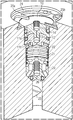
- Fig. 1 is a schematic illustration of a filling channel of a subsea device comprising a sealing cap in accordance with the present invention.
- FIG. 1 there is shown a filling channel of a subsea device which is equipped with a seat valve having a body 20 which in normal operating conditions is held in place by a spring 21 which in turn is held in place in the filling channel by a Seeger ring 22.
- a filling tool lifts the seat valve body 20 and fills the subsea device with oil or another dielectric liquid or a (isolating) gas via a flow channel 23.
- Valve body 20 When the filling process is complete the valve body 20 is released by the filling tool thereby closing off the filling channel.
- Valve body 20 may comprise an elastomeric seal 26 to improve the sealing of the seat valve.
- valve body 20 is released and the filling tool has been removed a sealing cap 10 is applied to the filling channel's opening in order to provide at least one additional barrier between the surrounding seawater and the oil (or dielectric fluid, or gas) filling of the subsea device when it is submerged.
- sealing cap 10 has a two-part body 11a, 11b to facilitate assembly of the sealing cap.
- a first cap element 11b has cylindrical section which constitutes a first part of a first cylindrical cap section having a first outer diameter which is marginally smaller than the inner diameter of the cylindrical opening the cap is supposed to seal so that the first cap element 11b by itself can move with little or no friction inside said opening.
- First cap element 11b has another cylindrical section which constitutes a third cylindrical cap section having a third diameter, wherein the third diameter is smaller than the first diameter.
- a third cylindrical cap section having a third diameter, wherein the third diameter is smaller than the first diameter.
- an axial seal type metal C-ring seal 12 is arranged.
- the dimension of the C-ring annular seal 13 is such that its inner diameter is slightly smaller than the third diameter and its outer diameter is greater than the first diameter and slightly greater than the inner diameter of the cylindrical opening the cap is supposed to seal.
- C-ring metal seals are often made of a spring steel to increase flexibility while at the same time exerting force against forces pressing the two "legs" of the C together.
- C-ring 13 is of the axial seal type meaning that the "C" is open in axial direction (i.e. the C is open on top or bottom of the C-ring if it lies on a flat surface).
- Such metal C-ring axial seals are also referred to as MCA seals by some manufacturers of such metal seals.
- a second cap element 11a is provided to keep the C-ring metal seal in place during the process of attaching or removing the cap.
- the second cap element 11a has a second part of the overall first cylindrical section, again having a diameter which is marginally smaller than the inner diameter of the cylindrical opening the cap is supposed to seal so that the second cap element 11a by itself can move with little or no friction inside said opening.
- Second cap element 11a is attached to the first cap element 11b such that a first annular groove 12 is formed by the third cylindrical cap section arranged between the first part of said first cylindrical cap section and the second part of said first cylindrical section, and metal C-ring seal 13 rests in this groove.
- the two parts of the seal body can be connected using any known method including but not limited to threaded connections, press-fitting or parallel key fitting.
- the two parts of the seal body are preferably made from stainless steel because this is a corrosion-resistant inexpensive material that can easily be processed with high precision. In other embodiments the parts of the seal body may be made of different metals or other materials.
- the C-ring is preferably made of spring spring steel and may be coated with a softer metal such as silver to increase tightness of the seal but may of course be made of other metals strong enough to reliably withstand the operating pressures of the respective application.
- the seal body is one piece constructed in and around the C-ring using some form of 3D printing or additive manufacturing.
- a sealing cap 10 in accordance with the invention is applied in the opening of the filling channel the filling channel has to barriers, one elastomeric at the bottom of seat valve body 20 and one metallic by virtue of cap 10.
- the cap itself is constructed to provide a double barrier.
- the body of sealing cap 10 comprises a second annular groove 14 which may be arranged in the same, first cylindrical cap section or in a different, second cylindrical cap section and an elastomeric O-ring seal 15 is arranged in said second groove which, when the sealing cap is applied to said opening, is in contact with a second inner circumference of the first or a second cylindrical section of said opening thereby providing a second sealing of the opening.
- first and second diameters of the first cylindrical cap section and the second cylindrical cap section are similar or even equal and the filling channel has a constant diameter at least in the area where the cap will be installed. It should be noted that while such a construction may have advantages, other embodiments provide for different first and second diameters, for example a second cylindrical cap section having a larger second diameter corresponding to a larger inner diameter of a second channel section towards the outer end of the cap.
- a weak link 24 which in the preferred embodiment is a C-type spring ring for easy installation in and removal from a corresponding groove at the outer end of the filling channel.
- the weak link is effected by two fingers 25a, 25b formed towards the center of the spring ring 24 which will bend or break off and release the cap if a pressure inside the subsea device becomes too large (i.e. exceeds a predefined pressure which i.a. is determined by the spring force of spring 21) and the seat valve 20 opens to release the pressure.
- the seat valve 20 and the cap 10 in conjunction operate as a pressure relief valve.
- This pressure relief is a safety measure especially useful if a faulty subsea device having (unwanted) gas inside is retrieved from the bottom of the sea. At the bottom of the sea the gas was contained by the subsea pressure but may lead to explosive relief when the subsea device is retrieved relatively quickly. Such explosive relief is prevented with the valve/cap combination of the present invention. Instead a controlled relief occurs by the internal pressure causing the seat valve to open and displacing cap 10.
Landscapes
- Engineering & Computer Science (AREA)
- General Engineering & Computer Science (AREA)
- Mechanical Engineering (AREA)
- Chemical & Material Sciences (AREA)
- Manufacturing & Machinery (AREA)
- Materials Engineering (AREA)
- Mechanical Coupling Of Light Guides (AREA)
- Safety Valves (AREA)
Priority Applications (1)
| Application Number | Priority Date | Filing Date | Title |
|---|---|---|---|
| EP17180749.8A EP3428492B1 (fr) | 2017-07-11 | 2017-07-11 | Bouchon d'étanchéité |
Applications Claiming Priority (1)
| Application Number | Priority Date | Filing Date | Title |
|---|---|---|---|
| EP17180749.8A EP3428492B1 (fr) | 2017-07-11 | 2017-07-11 | Bouchon d'étanchéité |
Publications (2)
| Publication Number | Publication Date |
|---|---|
| EP3428492A1 true EP3428492A1 (fr) | 2019-01-16 |
| EP3428492B1 EP3428492B1 (fr) | 2020-01-15 |
Family
ID=59325165
Family Applications (1)
| Application Number | Title | Priority Date | Filing Date |
|---|---|---|---|
| EP17180749.8A Active EP3428492B1 (fr) | 2017-07-11 | 2017-07-11 | Bouchon d'étanchéité |
Country Status (1)
| Country | Link |
|---|---|
| EP (1) | EP3428492B1 (fr) |
Cited By (1)
| Publication number | Priority date | Publication date | Assignee | Title |
|---|---|---|---|---|
| CN115973359A (zh) * | 2022-12-27 | 2023-04-18 | 上海中远船务工程有限公司 | 一种船舶海底阀箱水下封堵装置 |
Citations (8)
| Publication number | Priority date | Publication date | Assignee | Title |
|---|---|---|---|---|
| US2857073A (en) * | 1955-09-26 | 1958-10-21 | American Radiator & Standard | High pressure closure |
| US3690505A (en) * | 1970-04-07 | 1972-09-12 | Lummus Nederland Nv | Device for sealingly closing a metal pressure vessel |
| US4694859A (en) * | 1985-11-25 | 1987-09-22 | National Coupling Company, Inc. | Undersea hydraulic coupling and metal seal |
| US20030189053A1 (en) * | 2002-04-04 | 2003-10-09 | Felbaum John W. | Inert-metal lined steel-bodied vessel end-closure device |
| US20100096392A1 (en) * | 2006-10-04 | 2010-04-22 | Itsuo Kamiya | Cylindrical fixing flange structure and high-pressure gas container provided with the same (as amended) |
| WO2015113789A1 (fr) * | 2014-01-29 | 2015-08-06 | Siemens Aktiengesellschaft | Vanne pour un réservoir sous-marin sous pression |
| US20150252905A1 (en) * | 2014-03-04 | 2015-09-10 | Hans Espedalen | Valve for a Subsea Pressure Canister |
| WO2016126455A1 (fr) * | 2015-02-06 | 2016-08-11 | Dresser-Rand Company | Procédés pour fabrication additive d'un piston d'un seul tenant |
-
2017
- 2017-07-11 EP EP17180749.8A patent/EP3428492B1/fr active Active
Patent Citations (8)
| Publication number | Priority date | Publication date | Assignee | Title |
|---|---|---|---|---|
| US2857073A (en) * | 1955-09-26 | 1958-10-21 | American Radiator & Standard | High pressure closure |
| US3690505A (en) * | 1970-04-07 | 1972-09-12 | Lummus Nederland Nv | Device for sealingly closing a metal pressure vessel |
| US4694859A (en) * | 1985-11-25 | 1987-09-22 | National Coupling Company, Inc. | Undersea hydraulic coupling and metal seal |
| US20030189053A1 (en) * | 2002-04-04 | 2003-10-09 | Felbaum John W. | Inert-metal lined steel-bodied vessel end-closure device |
| US20100096392A1 (en) * | 2006-10-04 | 2010-04-22 | Itsuo Kamiya | Cylindrical fixing flange structure and high-pressure gas container provided with the same (as amended) |
| WO2015113789A1 (fr) * | 2014-01-29 | 2015-08-06 | Siemens Aktiengesellschaft | Vanne pour un réservoir sous-marin sous pression |
| US20150252905A1 (en) * | 2014-03-04 | 2015-09-10 | Hans Espedalen | Valve for a Subsea Pressure Canister |
| WO2016126455A1 (fr) * | 2015-02-06 | 2016-08-11 | Dresser-Rand Company | Procédés pour fabrication additive d'un piston d'un seul tenant |
Cited By (1)
| Publication number | Priority date | Publication date | Assignee | Title |
|---|---|---|---|---|
| CN115973359A (zh) * | 2022-12-27 | 2023-04-18 | 上海中远船务工程有限公司 | 一种船舶海底阀箱水下封堵装置 |
Also Published As
| Publication number | Publication date |
|---|---|
| EP3428492B1 (fr) | 2020-01-15 |
Similar Documents
| Publication | Publication Date | Title |
|---|---|---|
| US9267606B2 (en) | Seal arrangement for valve | |
| US5607165A (en) | Sealing system for a valve having biassed sealant under pressure | |
| CA2483234C (fr) | Soupape de surpression | |
| EP2976559B1 (fr) | Robinet-vanne doté d'un ensemble siège | |
| CA2965341C (fr) | Systeme de garniture comprime par un gaz pour vannes de commande | |
| US20210148477A1 (en) | Axial valve of the modular concept of construction | |
| CN104981640B (zh) | 回转顶轴阀促动器 | |
| GB2253467A (en) | Gate valve with hydraulic actuator. | |
| AU2015281295B2 (en) | High Integrity Pressure Protecting System (HIPPS) for a fluid line | |
| US9353870B2 (en) | Valve for a subsea pressure canister | |
| EP2902678A1 (fr) | Soupape pour récipient de pression sous-marine | |
| EP2584229B1 (fr) | Système et procédé de blindage d'un joint torique | |
| US3587632A (en) | Overpressure relief valve having a fail-safe releasable valve stem guide | |
| US5941530A (en) | Unidirectional environment barrier seal for subsea wellhead equipment and valves | |
| EP3428492B1 (fr) | Bouchon d'étanchéité | |
| US7604056B2 (en) | Downhole valve and method of making | |
| CN105402433B (zh) | 水下球阀的内外压力密封结构 | |
| EP2902679A1 (fr) | Soupape pour récipient de pression sous-marine | |
| US20200224781A1 (en) | Dual poppet pressure relief valve with vacuum adaptor capability | |
| US10533669B2 (en) | Bi-directional flow control valve | |
| US4442757A (en) | Fluid pressure actuator having bias element immersed in non-corrosive environment | |
| US3326516A (en) | High pressure plug valve | |
| RS66439B1 (sr) | Aksijalni ventil sa koncepcijom modularne konstrukcije | |
| US20050012063A1 (en) | Flexible metal sealing lip | |
| US3296890A (en) | Valve operator |
Legal Events
| Date | Code | Title | Description |
|---|---|---|---|
| PUAI | Public reference made under article 153(3) epc to a published international application that has entered the european phase |
Free format text: ORIGINAL CODE: 0009012 |
|
| STAA | Information on the status of an ep patent application or granted ep patent |
Free format text: STATUS: THE APPLICATION HAS BEEN PUBLISHED |
|
| AK | Designated contracting states |
Kind code of ref document: A1 Designated state(s): AL AT BE BG CH CY CZ DE DK EE ES FI FR GB GR HR HU IE IS IT LI LT LU LV MC MK MT NL NO PL PT RO RS SE SI SK SM TR |
|
| AX | Request for extension of the european patent |
Extension state: BA ME |
|
| STAA | Information on the status of an ep patent application or granted ep patent |
Free format text: STATUS: REQUEST FOR EXAMINATION WAS MADE |
|
| 17P | Request for examination filed |
Effective date: 20190503 |
|
| RBV | Designated contracting states (corrected) |
Designated state(s): AL AT BE BG CH CY CZ DE DK EE ES FI FR GB GR HR HU IE IS IT LI LT LU LV MC MK MT NL NO PL PT RO RS SE SI SK SM TR |
|
| GRAP | Despatch of communication of intention to grant a patent |
Free format text: ORIGINAL CODE: EPIDOSNIGR1 |
|
| STAA | Information on the status of an ep patent application or granted ep patent |
Free format text: STATUS: GRANT OF PATENT IS INTENDED |
|
| RIC1 | Information provided on ipc code assigned before grant |
Ipc: F16K 17/04 20060101AFI20190829BHEP Ipc: F16J 15/06 20060101ALI20190829BHEP Ipc: B33Y 80/00 20150101ALI20190829BHEP Ipc: F16J 15/08 20060101ALI20190829BHEP Ipc: F16J 13/24 20060101ALI20190829BHEP Ipc: F16K 17/14 20060101ALI20190829BHEP |
|
| INTG | Intention to grant announced |
Effective date: 20190924 |
|
| GRAS | Grant fee paid |
Free format text: ORIGINAL CODE: EPIDOSNIGR3 |
|
| GRAA | (expected) grant |
Free format text: ORIGINAL CODE: 0009210 |
|
| STAA | Information on the status of an ep patent application or granted ep patent |
Free format text: STATUS: THE PATENT HAS BEEN GRANTED |
|
| AK | Designated contracting states |
Kind code of ref document: B1 Designated state(s): AL AT BE BG CH CY CZ DE DK EE ES FI FR GB GR HR HU IE IS IT LI LT LU LV MC MK MT NL NO PL PT RO RS SE SI SK SM TR |
|
| REG | Reference to a national code |
Ref country code: CH Ref legal event code: EP Ref country code: GB Ref legal event code: FG4D |
|
| REG | Reference to a national code |
Ref country code: IE Ref legal event code: FG4D |
|
| REG | Reference to a national code |
Ref country code: DE Ref legal event code: R096 Ref document number: 602017010852 Country of ref document: DE |
|
| REG | Reference to a national code |
Ref country code: AT Ref legal event code: REF Ref document number: 1225448 Country of ref document: AT Kind code of ref document: T Effective date: 20200215 |
|
| REG | Reference to a national code |
Ref country code: NL Ref legal event code: MP Effective date: 20200115 |
|
| REG | Reference to a national code |
Ref country code: NO Ref legal event code: T2 Effective date: 20200115 |
|
| REG | Reference to a national code |
Ref country code: LT Ref legal event code: MG4D |
|
| PG25 | Lapsed in a contracting state [announced via postgrant information from national office to epo] |
Ref country code: RS Free format text: LAPSE BECAUSE OF FAILURE TO SUBMIT A TRANSLATION OF THE DESCRIPTION OR TO PAY THE FEE WITHIN THE PRESCRIBED TIME-LIMIT Effective date: 20200115 Ref country code: FI Free format text: LAPSE BECAUSE OF FAILURE TO SUBMIT A TRANSLATION OF THE DESCRIPTION OR TO PAY THE FEE WITHIN THE PRESCRIBED TIME-LIMIT Effective date: 20200115 Ref country code: PT Free format text: LAPSE BECAUSE OF FAILURE TO SUBMIT A TRANSLATION OF THE DESCRIPTION OR TO PAY THE FEE WITHIN THE PRESCRIBED TIME-LIMIT Effective date: 20200607 Ref country code: NL Free format text: LAPSE BECAUSE OF FAILURE TO SUBMIT A TRANSLATION OF THE DESCRIPTION OR TO PAY THE FEE WITHIN THE PRESCRIBED TIME-LIMIT Effective date: 20200115 |
|
| PG25 | Lapsed in a contracting state [announced via postgrant information from national office to epo] |
Ref country code: HR Free format text: LAPSE BECAUSE OF FAILURE TO SUBMIT A TRANSLATION OF THE DESCRIPTION OR TO PAY THE FEE WITHIN THE PRESCRIBED TIME-LIMIT Effective date: 20200115 Ref country code: IS Free format text: LAPSE BECAUSE OF FAILURE TO SUBMIT A TRANSLATION OF THE DESCRIPTION OR TO PAY THE FEE WITHIN THE PRESCRIBED TIME-LIMIT Effective date: 20200515 Ref country code: SE Free format text: LAPSE BECAUSE OF FAILURE TO SUBMIT A TRANSLATION OF THE DESCRIPTION OR TO PAY THE FEE WITHIN THE PRESCRIBED TIME-LIMIT Effective date: 20200115 Ref country code: LV Free format text: LAPSE BECAUSE OF FAILURE TO SUBMIT A TRANSLATION OF THE DESCRIPTION OR TO PAY THE FEE WITHIN THE PRESCRIBED TIME-LIMIT Effective date: 20200115 Ref country code: BG Free format text: LAPSE BECAUSE OF FAILURE TO SUBMIT A TRANSLATION OF THE DESCRIPTION OR TO PAY THE FEE WITHIN THE PRESCRIBED TIME-LIMIT Effective date: 20200415 Ref country code: GR Free format text: LAPSE BECAUSE OF FAILURE TO SUBMIT A TRANSLATION OF THE DESCRIPTION OR TO PAY THE FEE WITHIN THE PRESCRIBED TIME-LIMIT Effective date: 20200416 |
|
| REG | Reference to a national code |
Ref country code: DE Ref legal event code: R097 Ref document number: 602017010852 Country of ref document: DE |
|
| PG25 | Lapsed in a contracting state [announced via postgrant information from national office to epo] |
Ref country code: SK Free format text: LAPSE BECAUSE OF FAILURE TO SUBMIT A TRANSLATION OF THE DESCRIPTION OR TO PAY THE FEE WITHIN THE PRESCRIBED TIME-LIMIT Effective date: 20200115 Ref country code: RO Free format text: LAPSE BECAUSE OF FAILURE TO SUBMIT A TRANSLATION OF THE DESCRIPTION OR TO PAY THE FEE WITHIN THE PRESCRIBED TIME-LIMIT Effective date: 20200115 Ref country code: LT Free format text: LAPSE BECAUSE OF FAILURE TO SUBMIT A TRANSLATION OF THE DESCRIPTION OR TO PAY THE FEE WITHIN THE PRESCRIBED TIME-LIMIT Effective date: 20200115 Ref country code: CZ Free format text: LAPSE BECAUSE OF FAILURE TO SUBMIT A TRANSLATION OF THE DESCRIPTION OR TO PAY THE FEE WITHIN THE PRESCRIBED TIME-LIMIT Effective date: 20200115 Ref country code: ES Free format text: LAPSE BECAUSE OF FAILURE TO SUBMIT A TRANSLATION OF THE DESCRIPTION OR TO PAY THE FEE WITHIN THE PRESCRIBED TIME-LIMIT Effective date: 20200115 Ref country code: DK Free format text: LAPSE BECAUSE OF FAILURE TO SUBMIT A TRANSLATION OF THE DESCRIPTION OR TO PAY THE FEE WITHIN THE PRESCRIBED TIME-LIMIT Effective date: 20200115 Ref country code: EE Free format text: LAPSE BECAUSE OF FAILURE TO SUBMIT A TRANSLATION OF THE DESCRIPTION OR TO PAY THE FEE WITHIN THE PRESCRIBED TIME-LIMIT Effective date: 20200115 Ref country code: SM Free format text: LAPSE BECAUSE OF FAILURE TO SUBMIT A TRANSLATION OF THE DESCRIPTION OR TO PAY THE FEE WITHIN THE PRESCRIBED TIME-LIMIT Effective date: 20200115 |
|
| REG | Reference to a national code |
Ref country code: AT Ref legal event code: MK05 Ref document number: 1225448 Country of ref document: AT Kind code of ref document: T Effective date: 20200115 |
|
| PLBE | No opposition filed within time limit |
Free format text: ORIGINAL CODE: 0009261 |
|
| STAA | Information on the status of an ep patent application or granted ep patent |
Free format text: STATUS: NO OPPOSITION FILED WITHIN TIME LIMIT |
|
| 26N | No opposition filed |
Effective date: 20201016 |
|
| PG25 | Lapsed in a contracting state [announced via postgrant information from national office to epo] |
Ref country code: IT Free format text: LAPSE BECAUSE OF FAILURE TO SUBMIT A TRANSLATION OF THE DESCRIPTION OR TO PAY THE FEE WITHIN THE PRESCRIBED TIME-LIMIT Effective date: 20200115 Ref country code: AT Free format text: LAPSE BECAUSE OF FAILURE TO SUBMIT A TRANSLATION OF THE DESCRIPTION OR TO PAY THE FEE WITHIN THE PRESCRIBED TIME-LIMIT Effective date: 20200115 |
|
| REG | Reference to a national code |
Ref country code: DE Ref legal event code: R119 Ref document number: 602017010852 Country of ref document: DE |
|
| PG25 | Lapsed in a contracting state [announced via postgrant information from national office to epo] |
Ref country code: SI Free format text: LAPSE BECAUSE OF FAILURE TO SUBMIT A TRANSLATION OF THE DESCRIPTION OR TO PAY THE FEE WITHIN THE PRESCRIBED TIME-LIMIT Effective date: 20200115 Ref country code: PL Free format text: LAPSE BECAUSE OF FAILURE TO SUBMIT A TRANSLATION OF THE DESCRIPTION OR TO PAY THE FEE WITHIN THE PRESCRIBED TIME-LIMIT Effective date: 20200115 Ref country code: MC Free format text: LAPSE BECAUSE OF FAILURE TO SUBMIT A TRANSLATION OF THE DESCRIPTION OR TO PAY THE FEE WITHIN THE PRESCRIBED TIME-LIMIT Effective date: 20200115 |
|
| REG | Reference to a national code |
Ref country code: CH Ref legal event code: PL |
|
| REG | Reference to a national code |
Ref country code: NO Ref legal event code: CHAD Owner name: SIEMENS ENERGY AS, NO |
|
| REG | Reference to a national code |
Ref country code: GB Ref legal event code: 732E Free format text: REGISTERED BETWEEN 20210325 AND 20210331 |
|
| REG | Reference to a national code |
Ref country code: BE Ref legal event code: MM Effective date: 20200731 |
|
| PG25 | Lapsed in a contracting state [announced via postgrant information from national office to epo] |
Ref country code: CH Free format text: LAPSE BECAUSE OF NON-PAYMENT OF DUE FEES Effective date: 20200731 Ref country code: LI Free format text: LAPSE BECAUSE OF NON-PAYMENT OF DUE FEES Effective date: 20200731 Ref country code: LU Free format text: LAPSE BECAUSE OF NON-PAYMENT OF DUE FEES Effective date: 20200711 Ref country code: FR Free format text: LAPSE BECAUSE OF NON-PAYMENT OF DUE FEES Effective date: 20200731 |
|
| PG25 | Lapsed in a contracting state [announced via postgrant information from national office to epo] |
Ref country code: DE Free format text: LAPSE BECAUSE OF NON-PAYMENT OF DUE FEES Effective date: 20210202 Ref country code: BE Free format text: LAPSE BECAUSE OF NON-PAYMENT OF DUE FEES Effective date: 20200731 |
|
| PG25 | Lapsed in a contracting state [announced via postgrant information from national office to epo] |
Ref country code: IE Free format text: LAPSE BECAUSE OF NON-PAYMENT OF DUE FEES Effective date: 20200711 |
|
| PG25 | Lapsed in a contracting state [announced via postgrant information from national office to epo] |
Ref country code: TR Free format text: LAPSE BECAUSE OF FAILURE TO SUBMIT A TRANSLATION OF THE DESCRIPTION OR TO PAY THE FEE WITHIN THE PRESCRIBED TIME-LIMIT Effective date: 20200115 Ref country code: MT Free format text: LAPSE BECAUSE OF FAILURE TO SUBMIT A TRANSLATION OF THE DESCRIPTION OR TO PAY THE FEE WITHIN THE PRESCRIBED TIME-LIMIT Effective date: 20200115 Ref country code: CY Free format text: LAPSE BECAUSE OF FAILURE TO SUBMIT A TRANSLATION OF THE DESCRIPTION OR TO PAY THE FEE WITHIN THE PRESCRIBED TIME-LIMIT Effective date: 20200115 |
|
| PG25 | Lapsed in a contracting state [announced via postgrant information from national office to epo] |
Ref country code: MK Free format text: LAPSE BECAUSE OF FAILURE TO SUBMIT A TRANSLATION OF THE DESCRIPTION OR TO PAY THE FEE WITHIN THE PRESCRIBED TIME-LIMIT Effective date: 20200115 Ref country code: AL Free format text: LAPSE BECAUSE OF FAILURE TO SUBMIT A TRANSLATION OF THE DESCRIPTION OR TO PAY THE FEE WITHIN THE PRESCRIBED TIME-LIMIT Effective date: 20200115 |
|
| PGFP | Annual fee paid to national office [announced via postgrant information from national office to epo] |
Ref country code: NO Payment date: 20250718 Year of fee payment: 9 |
|
| PGFP | Annual fee paid to national office [announced via postgrant information from national office to epo] |
Ref country code: GB Payment date: 20250722 Year of fee payment: 9 |