EP3428540A1 - Dispositif de plaque de cuisson pourvu de plaque de cuisson et champs de cuisson - Google Patents
Dispositif de plaque de cuisson pourvu de plaque de cuisson et champs de cuisson Download PDFInfo
- Publication number
- EP3428540A1 EP3428540A1 EP18181082.1A EP18181082A EP3428540A1 EP 3428540 A1 EP3428540 A1 EP 3428540A1 EP 18181082 A EP18181082 A EP 18181082A EP 3428540 A1 EP3428540 A1 EP 3428540A1
- Authority
- EP
- European Patent Office
- Prior art keywords
- hotplate
- ring
- locking
- latching
- protruding
- Prior art date
- Legal status (The legal status is an assumption and is not a legal conclusion. Google has not performed a legal analysis and makes no representation as to the accuracy of the status listed.)
- Granted
Links
Images


Classifications
-
- F—MECHANICAL ENGINEERING; LIGHTING; HEATING; WEAPONS; BLASTING
- F24—HEATING; RANGES; VENTILATING
- F24C—DOMESTIC STOVES OR RANGES ; DETAILS OF DOMESTIC STOVES OR RANGES, OF GENERAL APPLICATION
- F24C7/00—Stoves or ranges heated by electric energy
- F24C7/06—Arrangement or mounting of electric heating elements
- F24C7/067—Arrangement or mounting of electric heating elements on ranges
-
- F—MECHANICAL ENGINEERING; LIGHTING; HEATING; WEAPONS; BLASTING
- F24—HEATING; RANGES; VENTILATING
- F24C—DOMESTIC STOVES OR RANGES ; DETAILS OF DOMESTIC STOVES OR RANGES, OF GENERAL APPLICATION
- F24C15/00—Details
- F24C15/10—Tops, e.g. hot plates; Rings
-
- F—MECHANICAL ENGINEERING; LIGHTING; HEATING; WEAPONS; BLASTING
- F24—HEATING; RANGES; VENTILATING
- F24C—DOMESTIC STOVES OR RANGES ; DETAILS OF DOMESTIC STOVES OR RANGES, OF GENERAL APPLICATION
- F24C15/00—Details
- F24C15/10—Tops, e.g. hot plates; Rings
- F24C15/108—Mounting of hot plate on worktop
-
- H—ELECTRICITY
- H05—ELECTRIC TECHNIQUES NOT OTHERWISE PROVIDED FOR
- H05B—ELECTRIC HEATING; ELECTRIC LIGHT SOURCES NOT OTHERWISE PROVIDED FOR; CIRCUIT ARRANGEMENTS FOR ELECTRIC LIGHT SOURCES, IN GENERAL
- H05B3/00—Ohmic-resistance heating
- H05B3/68—Heating arrangements specially adapted for cooking plates or analogous hot-plates
Definitions
- the invention has for its object to provide an aforementioned hotplate device and provided with at least one such hotplate cooking hob with which problems of the prior art can be solved and it is possible in particular, a hot plate simple, safe and without harmful effects on a To be able to fasten the hob.
- a hotplate device with the features of claim 1 and provided with at least one such hob device hob with the features of claim 14.
- Advantageous and preferred embodiments of the invention are the subject of further claims and are explained in more detail below. Some of the features mentioned below are described only for the hotplate device or only for the hob. However, they should be able to apply independently and independently of each other for both the hotplate device and the hob. The wording of the claims is incorporated herein by express reference.
- a plurality of said recesses or latching projections may be provided in a direction away from the top of the cooking plate in a row and, so to speak, have different distance to the top.
- quasi different locking depths can be provided, whereby it is possible to produce the locking connection with different insertion depth of the cooking plate with ring portion in the receiving opening of the hob plate.
- a plurality of successively spaced locking projections or recesses could be attached to the mounting ring, but what makes its formation predictably much more complicated.
- This locking connection by means of fastening ring holds the hotplate on the hob plate of the hob when the mounting ring is additionally supported on the hob plate and the underside.
- the bias is advantageously provided for supporting, in particular to keep the locking connection without play.
- the fastening ring may have a diameter which is greater than that of the ring portion.
- the diameter may be 1% to 5% larger, in other words, a radial distance between the two parts may be between 1 mm and 10 mm.
- the distance of the mounting ring to the ring portion should not be too large, so that no disturbing offset between the parts may arise. At the same time a locking effect should be possible as well as possible.
- the continuously encircling annular body has said spacing.
- Said locking projections on the encircling annular body of the fastening ring can advantageously be provided as separate parts and attached thereto.
- Particularly advantageous annular body and locking projections are formed of metal and are joined together by welding. Even if a recess on the annular portion of the hotplate body is provided circumferentially or continuously, it is recommended that the locking projections do not form continuously, so that they are preferably provided evenly distributed for a uniform and secure latching connection.
- the locking connection is significantly better with improved locking function of the locking projections of the mounting ring, if there are individual locking projections, which are formed separately from each other.
- three, four or six such locking projections are provided.
- the second latching leg of the latching projections can form the radially innermost region of the fastening ring. Its radius may be 1 mm to 10 mm lower than that of the rotating ring body. It can be 0.5 mm to 2 mm or even 3 mm deep seen in the radial direction in the ring portion engage in corresponding recesses.
- the locking projections described may be provided or attached to a region, in particular at a plurality of equally distributed areas.
- they are provided as separate parts on an underside of the radially outwardly bent second leg of the fastening ring. So they form part of the mounting ring, which is farthest from the hob plate so that the rotating ring body of the mounting ring can rest against the underside of the hob plate.
- the latching connection means have at least two separate latching clips for the hotplate in order to secure it to the cooktop by means of the short tubular ring section.
- a latching clip advantageously has a resilient latching limb or a latching section, which corresponds to the aforementioned latching projection on the fastening ring, for a latching connection with the recessed latching recess or with the protruding latching projection of the short tube-like ring section or to engage therein.
- the locking clip also has a mounting leg or a mounting portion, with which it is supported from below against the hob plate.
- Recessed recesses are preferably attached to the outside of the protruding ring portion of the hotplate body. They may be at least 40% of the height of the ring portion remote from the bottom of the hotplate body or away from the connection of the protruding ring portion to the hotplate body. It is advantageous in about 60% to 70% of the height.
- the locking recess should not be just at the extreme end of the ring portion, but at the same time not too close to the hob plate to allow a reliably producible latching connection.
- this distance from the free end of the protruding ring portion may be at least 1 mm, more preferably at least 4 mm.
- the isolated recesses may for example have a length which is at most 1% to 10% longer than a length of the protruding locking projections on the annular body.
- a rotation is provided only for a single recess on the ring portion and a single locking projection on the mounting ring, which satisfies this function sufficiently.
- a continuous circumferential groove is provided on the outside of the ring section, which groove forms the recessed catch recess for a plurality of latching projections of the fastening ring. This can be made very easily by twisting off the hotplate body.
- a recess or a projection is provided on the inner edge of the receiving opening.
- a corresponding projection or a corresponding recess may be provided on the fastening ring. This allows both a specification of the mounting position and, above all, an advantageous anti-twist device can be achieved.
- a recess could be relatively easily punched out in the edge of the receiving opening during their production, for example by a correspondingly changed punching tool, alternatively, it can also be introduced later.
- a corresponding projection can be made, for example by bending out a section or a kind of tab, which then rests in the recess on the inner edge of the receiving opening.
- the hotplate device 20 itself has a hotplate 22 with a hotplate body 23 having a top 25 and a bottom 26.
- the top 25 is largely flat as a well-known hotplate.
- From the bottom 26 is a ring portion 28 from or is integrally formed, it is approximately at right angles to the top 25 and may be about 1 cm to 2 cm long in practice.
- Radially outside the ring portion 28 is a protruding Outer edge 29 is provided on the hotplate body 23.
- the cooking plate 22 is formed in principle as far as known in the art.
- the locking recesses 32a and 32b are formed identically in principle and extend, so to speak, obliquely into the outer side 30 of the annular portion 28, for example at an angle of about 10 ° to 15 °. Their distance from each other can be a few millimeters, for example 3 mm to 6 mm.
- the latching projection 41 has a first fastening leg 42, which extends parallel to the second leg 39 of the annular body 37 and is secured thereto, is advantageously welded firmly.
- a second latching leg 43 of the latching projection 41 is bent at an angle thereto, advantageously at an angle of about 100 ° to 110 °.
- the latching projection 41 is advantageously made of bent sheet metal, for example with a half thickness compared to the annular body 37, for example 1 mm to 2 mm.
- the length of the second locking leg 43 in cross section may be about 8 mm to 12 mm or even up to 15 mm.
- a cooking plate 22 with a preassembled cover ring 45 is inserted over the ring section 28 from the upper side 14 into the receiving opening 18. It should be in a desired or predetermined rotational position. Then, at the bottom 15 of the hob plate 13 of the mounting ring 35 is guided over the ring portion 28, possibly also in exactly predetermined rotational position zuein other. While the annular body 37 protrudes with its first leg 38 through the receiving opening 18 so that it rests with the second leg 39 on the underside 15 of the hob plate 13 at the edge of the receiving opening 18, the lower end of the locking leg 43 of the locking projection 41 engages in the Detent recess 32b and holds the hotplate 22 thus fixed to the annular portion 28 against the hob plate thirteenth
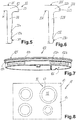
- a in Fig. 3 Dashed index projection 40 may be provided at a specific location. He can cooperate with an easily imaginable correspondingly formed recess on the inner edge of the receiving opening 18 such that it engages against rotation in this. If the fastening ring 35 in a similar form against rotation of the cooking plate 22 and its annular portion 28 is formed, a total of rotation can be achieved. Thus, a rotation of the mounting ring 35 relative to the hob plate 13 could be positively prevented and not only frictionally as in the Fig. 1 ,
- An anti-rotation of a cooking plate 22 on a hob plate 13 can not only by the configuration of the hotplate body 123 accordingly Fig. 7 or an index tab 40 accordingly Fig. 3 be reached, but also alone by friction by friction, when the four locking projections 41 and latching leg 43 according to the Fig. 3 in the recesses 32a or 32b according to the Fig. 4 engage the ring section 28.
- Fig. 5 In the sectional view of Fig. 5 is again the hot plate 22 from the Fig. 1 shown removed. It can be seen how the bottom of the hotplate body 23 protrudes with a flat top 25 and outer edge 29 of the ring portion 28, its circumferential configuration is from the Fig. 4 good to see.
- the two recesses 32a and 32b to recognize each other which are formed as inclined recesses. Their distance from each other is relatively small, so that a relatively fine gradation of locking depths is possible.
- the upper recess 32a are used. It could also easily be provided more recesses.
- openings are provided at a distance from each outer edge, alternatively also at the lower edge, through which a tool can be introduced, for example, a small screwdriver to release the locking connection again.
- the locking leg 43 can be bent radially outwards and thus out of the recess 32b. If this is done for all locking legs 43 of the locking projections 41 together with corresponding recesses, for example, one after the other, the mounting ring 35 can be removed again and the hot plate 22 can be removed, for example, be replaced.
- a locking clip 341 is provided in sectional view, which advantageously consists of thin sheet metal with a thickness of, for example, 0.7 mm to 1.5 mm and has a certain shape.
- a radially outwardly projecting mounting leg 342 it is supported against the bottom 315 of the hob plate 313 close to the receiving opening 318 and against the lower inner edge.
- Downwards is an elongated locking leg 343, similar to the locking projection 41 of the mounting ring 35 according to Fig. 1 ,
- the locking leg 343 is in the lower recess 332b locked and by supporting against the bottom 315 of the hob plate 313 he holds the hot plate 320 fixed to the hob 311st
Landscapes
- Engineering & Computer Science (AREA)
- Chemical & Material Sciences (AREA)
- Combustion & Propulsion (AREA)
- Mechanical Engineering (AREA)
- General Engineering & Computer Science (AREA)
- Baking, Grill, Roasting (AREA)
- Portable Nailing Machines And Staplers (AREA)
- Gas Burners (AREA)
- Connection Of Plates (AREA)
- Cookers (AREA)
Priority Applications (1)
| Application Number | Priority Date | Filing Date | Title |
|---|---|---|---|
| PL18181082T PL3428540T3 (pl) | 2017-07-11 | 2018-07-02 | Urządzenie do płyty grzejnej z płytą grzejną i płytą kuchenną |
Applications Claiming Priority (1)
| Application Number | Priority Date | Filing Date | Title |
|---|---|---|---|
| DE102017211812.1A DE102017211812A1 (de) | 2017-07-11 | 2017-07-11 | Kochplattenvorrichtung mit einer Kochplatte und Kochfeld |
Publications (2)
| Publication Number | Publication Date |
|---|---|
| EP3428540A1 true EP3428540A1 (fr) | 2019-01-16 |
| EP3428540B1 EP3428540B1 (fr) | 2020-04-01 |
Family
ID=62845981
Family Applications (1)
| Application Number | Title | Priority Date | Filing Date |
|---|---|---|---|
| EP18181082.1A Active EP3428540B1 (fr) | 2017-07-11 | 2018-07-02 | Dispositif de plaque de cuisson pourvu de plaque de cuisson et champs de cuisson |
Country Status (6)
| Country | Link |
|---|---|
| EP (1) | EP3428540B1 (fr) |
| CN (1) | CN109237553B (fr) |
| DE (1) | DE102017211812A1 (fr) |
| PL (1) | PL3428540T3 (fr) |
| RU (1) | RU2768337C2 (fr) |
| ZA (1) | ZA201804474B (fr) |
Cited By (1)
| Publication number | Priority date | Publication date | Assignee | Title |
|---|---|---|---|---|
| US12264824B2 (en) | 2021-05-14 | 2025-04-01 | Electrolux Home Products, Inc. | Spring clip for mounting a heating element in a cooktop |
Citations (3)
| Publication number | Priority date | Publication date | Assignee | Title |
|---|---|---|---|---|
| DE1579656A1 (de) * | 1966-09-14 | 1970-09-10 | Ego Elektro Blanc & Fischer | Befestigungsvorrichtung fuer eine Kochplatte an einer Herdplatte |
| EP0047490A2 (fr) * | 1980-09-09 | 1982-03-17 | E.G.O. Elektro-Geräte Blanc u. Fischer | Réchaud électrique |
| EP0957661A2 (fr) | 1998-05-12 | 1999-11-17 | E.G.O. ELEKTRO-GERÄTEBAU GmbH | Plaque de cuisson électrique |
Family Cites Families (10)
| Publication number | Priority date | Publication date | Assignee | Title |
|---|---|---|---|---|
| DE1004786B (de) * | 1952-10-04 | 1957-03-21 | Karl Fischer | Elektrische Massekochplatte |
| CH306009A (fr) * | 1953-02-09 | 1955-03-31 | Le Reve Sa | Plaque de cuisson pour cuisinière. |
| DE2755807C3 (de) * | 1977-12-14 | 1981-10-22 | Karl 7519 Oberderdingen Fischer | Elektrokochplatte mit einem Tragring zum Einbau in eine Kochmulde, ein Herdoberteil o.dgl. |
| DE3324783A1 (de) * | 1983-07-08 | 1985-01-17 | Bosch-Siemens Hausgeräte GmbH, 7000 Stuttgart | Kochmulde |
| DE8702478U1 (de) * | 1987-02-18 | 1988-06-16 | E.G.O. Elektro-Geräte Blanc u. Fischer, 7519 Oberderdingen | Kochgerät |
| US5241158A (en) * | 1988-07-21 | 1993-08-31 | E.G.O. Elektro-Gerate Blanc U. Fischer | Electric hotplate |
| DE19854228B4 (de) * | 1998-11-24 | 2007-09-27 | BSH Bosch und Siemens Hausgeräte GmbH | Kochfeld mit Montagerahmen in Biegetechnik |
| DE102007044239A1 (de) * | 2007-09-17 | 2009-03-19 | BSH Bosch und Siemens Hausgeräte GmbH | Kochfeld mit einem Zierrahmen und einem damit verbundenen Montagerahmen und Verfahren zum Verbinden des Zierrahmens mit dem Montagerahmen |
| RU2606146C2 (ru) * | 2014-06-19 | 2017-01-10 | Сер Даяныклы Тюкетим Маллары Ич Ве Диш Тиджарет Санайи Аноним Ширкети | Кухонная плита |
| CN205385615U (zh) * | 2016-01-28 | 2016-07-13 | 东莞市欣能电器有限公司 | 加热装置及其锁扣机构 |
-
2017
- 2017-07-11 DE DE102017211812.1A patent/DE102017211812A1/de not_active Ceased
-
2018
- 2018-07-02 PL PL18181082T patent/PL3428540T3/pl unknown
- 2018-07-02 EP EP18181082.1A patent/EP3428540B1/fr active Active
- 2018-07-04 ZA ZA2018/04474A patent/ZA201804474B/en unknown
- 2018-07-05 RU RU2018124651A patent/RU2768337C2/ru active
- 2018-07-11 CN CN201810757004.2A patent/CN109237553B/zh active Active
Patent Citations (3)
| Publication number | Priority date | Publication date | Assignee | Title |
|---|---|---|---|---|
| DE1579656A1 (de) * | 1966-09-14 | 1970-09-10 | Ego Elektro Blanc & Fischer | Befestigungsvorrichtung fuer eine Kochplatte an einer Herdplatte |
| EP0047490A2 (fr) * | 1980-09-09 | 1982-03-17 | E.G.O. Elektro-Geräte Blanc u. Fischer | Réchaud électrique |
| EP0957661A2 (fr) | 1998-05-12 | 1999-11-17 | E.G.O. ELEKTRO-GERÄTEBAU GmbH | Plaque de cuisson électrique |
Cited By (1)
| Publication number | Priority date | Publication date | Assignee | Title |
|---|---|---|---|---|
| US12264824B2 (en) | 2021-05-14 | 2025-04-01 | Electrolux Home Products, Inc. | Spring clip for mounting a heating element in a cooktop |
Also Published As
| Publication number | Publication date |
|---|---|
| RU2018124651A3 (fr) | 2021-09-30 |
| PL3428540T3 (pl) | 2020-09-21 |
| RU2768337C2 (ru) | 2022-03-23 |
| ZA201804474B (en) | 2019-03-27 |
| DE102017211812A1 (de) | 2019-01-17 |
| CN109237553B (zh) | 2022-07-19 |
| RU2018124651A (ru) | 2020-01-09 |
| CN109237553A (zh) | 2019-01-18 |
| EP3428540B1 (fr) | 2020-04-01 |
Similar Documents
| Publication | Publication Date | Title |
|---|---|---|
| DE102007009616B4 (de) | Befestigungseinheit | |
| EP2649329B1 (fr) | Vis comprenant une tête, une tige et une collerette ondulée conique | |
| DE6753463U (de) | Befestigungselement | |
| DE102014011583B3 (de) | Schlauchkupplung | |
| DE202008012826U1 (de) | Deckel mit Dampfentlüftungsfunktion | |
| DE102012201543B4 (de) | Sanitärventil | |
| DE102016118640A1 (de) | Federelement | |
| EP1947392A2 (fr) | Champ de cuisson | |
| EP3117046B1 (fr) | Support intermédiaire | |
| EP3428540A1 (fr) | Dispositif de plaque de cuisson pourvu de plaque de cuisson et champs de cuisson | |
| DE102007042034A1 (de) | Befestigungssystem zum Befestigen von Bauelementen, insbesondere für Kraftfahrzeuge | |
| EP2565351B1 (fr) | Agencement de poignée | |
| EP3912513B1 (fr) | Parement pour un meuble de cuisine | |
| EP3111145B1 (fr) | Appareil électroménager doté d'un élément de fixation | |
| EP1039043A2 (fr) | Robinetterie sanitaire avec un écrou pour sa fixation | |
| DE102015000303B3 (de) | Schublade für ein Möbel | |
| DE202013001813U1 (de) | Klemmelement | |
| DE102017011237A1 (de) | Befestigungsteil und Dachanordnung | |
| DE1950156A1 (de) | Herdplatte bzw. Herdmulde | |
| AT509850B1 (de) | Behälter zur aufnahme von gewürzen | |
| AT510146B1 (de) | Gewürzmühle | |
| EP0352232A1 (fr) | Elément de support pour tuyaux de descentes d'eau | |
| EP3206459B1 (fr) | Plaque de cuisson et plan de cuisson comprenant une plaque de cuisson | |
| AT501009B1 (de) | Vorrichtung zum aneinander fixieren und lösen von zueinander teleskopierbaren profilen | |
| DE102009008454A1 (de) | Nivellierhilfe für Holz-/Balken-Unterkonstruktionen insbesondere von Balkon- und Terassenabdeckungen |
Legal Events
| Date | Code | Title | Description |
|---|---|---|---|
| PUAI | Public reference made under article 153(3) epc to a published international application that has entered the european phase |
Free format text: ORIGINAL CODE: 0009012 |
|
| STAA | Information on the status of an ep patent application or granted ep patent |
Free format text: STATUS: THE APPLICATION HAS BEEN PUBLISHED |
|
| AK | Designated contracting states |
Kind code of ref document: A1 Designated state(s): AL AT BE BG CH CY CZ DE DK EE ES FI FR GB GR HR HU IE IS IT LI LT LU LV MC MK MT NL NO PL PT RO RS SE SI SK SM TR |
|
| AX | Request for extension of the european patent |
Extension state: BA ME |
|
| STAA | Information on the status of an ep patent application or granted ep patent |
Free format text: STATUS: REQUEST FOR EXAMINATION WAS MADE |
|
| 17P | Request for examination filed |
Effective date: 20190703 |
|
| RBV | Designated contracting states (corrected) |
Designated state(s): AL AT BE BG CH CY CZ DE DK EE ES FI FR GB GR HR HU IE IS IT LI LT LU LV MC MK MT NL NO PL PT RO RS SE SI SK SM TR |
|
| GRAP | Despatch of communication of intention to grant a patent |
Free format text: ORIGINAL CODE: EPIDOSNIGR1 |
|
| STAA | Information on the status of an ep patent application or granted ep patent |
Free format text: STATUS: GRANT OF PATENT IS INTENDED |
|
| INTG | Intention to grant announced |
Effective date: 20191118 |
|
| GRAS | Grant fee paid |
Free format text: ORIGINAL CODE: EPIDOSNIGR3 |
|
| GRAA | (expected) grant |
Free format text: ORIGINAL CODE: 0009210 |
|
| STAA | Information on the status of an ep patent application or granted ep patent |
Free format text: STATUS: THE PATENT HAS BEEN GRANTED |
|
| RAP1 | Party data changed (applicant data changed or rights of an application transferred) |
Owner name: E.G.O. ELEKTRO-GERAETEBAU GMBH |
|
| AK | Designated contracting states |
Kind code of ref document: B1 Designated state(s): AL AT BE BG CH CY CZ DE DK EE ES FI FR GB GR HR HU IE IS IT LI LT LU LV MC MK MT NL NO PL PT RO RS SE SI SK SM TR |
|
| REG | Reference to a national code |
Ref country code: GB Ref legal event code: FG4D Free format text: NOT ENGLISH |
|
| REG | Reference to a national code |
Ref country code: CH Ref legal event code: EP Ref country code: AT Ref legal event code: REF Ref document number: 1251829 Country of ref document: AT Kind code of ref document: T Effective date: 20200415 |
|
| REG | Reference to a national code |
Ref country code: DE Ref legal event code: R096 Ref document number: 502018001074 Country of ref document: DE |
|
| REG | Reference to a national code |
Ref country code: IE Ref legal event code: FG4D Free format text: LANGUAGE OF EP DOCUMENT: GERMAN |
|
| PG25 | Lapsed in a contracting state [announced via postgrant information from national office to epo] |
Ref country code: BG Free format text: LAPSE BECAUSE OF FAILURE TO SUBMIT A TRANSLATION OF THE DESCRIPTION OR TO PAY THE FEE WITHIN THE PRESCRIBED TIME-LIMIT Effective date: 20200701 |
|
| REG | Reference to a national code |
Ref country code: NL Ref legal event code: MP Effective date: 20200401 |
|
| REG | Reference to a national code |
Ref country code: LT Ref legal event code: MG4D |
|
| PG25 | Lapsed in a contracting state [announced via postgrant information from national office to epo] |
Ref country code: CZ Free format text: LAPSE BECAUSE OF FAILURE TO SUBMIT A TRANSLATION OF THE DESCRIPTION OR TO PAY THE FEE WITHIN THE PRESCRIBED TIME-LIMIT Effective date: 20200401 Ref country code: NO Free format text: LAPSE BECAUSE OF FAILURE TO SUBMIT A TRANSLATION OF THE DESCRIPTION OR TO PAY THE FEE WITHIN THE PRESCRIBED TIME-LIMIT Effective date: 20200701 Ref country code: GR Free format text: LAPSE BECAUSE OF FAILURE TO SUBMIT A TRANSLATION OF THE DESCRIPTION OR TO PAY THE FEE WITHIN THE PRESCRIBED TIME-LIMIT Effective date: 20200702 Ref country code: IS Free format text: LAPSE BECAUSE OF FAILURE TO SUBMIT A TRANSLATION OF THE DESCRIPTION OR TO PAY THE FEE WITHIN THE PRESCRIBED TIME-LIMIT Effective date: 20200801 Ref country code: PT Free format text: LAPSE BECAUSE OF FAILURE TO SUBMIT A TRANSLATION OF THE DESCRIPTION OR TO PAY THE FEE WITHIN THE PRESCRIBED TIME-LIMIT Effective date: 20200817 Ref country code: LT Free format text: LAPSE BECAUSE OF FAILURE TO SUBMIT A TRANSLATION OF THE DESCRIPTION OR TO PAY THE FEE WITHIN THE PRESCRIBED TIME-LIMIT Effective date: 20200401 Ref country code: SE Free format text: LAPSE BECAUSE OF FAILURE TO SUBMIT A TRANSLATION OF THE DESCRIPTION OR TO PAY THE FEE WITHIN THE PRESCRIBED TIME-LIMIT Effective date: 20200401 Ref country code: NL Free format text: LAPSE BECAUSE OF FAILURE TO SUBMIT A TRANSLATION OF THE DESCRIPTION OR TO PAY THE FEE WITHIN THE PRESCRIBED TIME-LIMIT Effective date: 20200401 Ref country code: FI Free format text: LAPSE BECAUSE OF FAILURE TO SUBMIT A TRANSLATION OF THE DESCRIPTION OR TO PAY THE FEE WITHIN THE PRESCRIBED TIME-LIMIT Effective date: 20200401 |
|
| PG25 | Lapsed in a contracting state [announced via postgrant information from national office to epo] |
Ref country code: HR Free format text: LAPSE BECAUSE OF FAILURE TO SUBMIT A TRANSLATION OF THE DESCRIPTION OR TO PAY THE FEE WITHIN THE PRESCRIBED TIME-LIMIT Effective date: 20200401 Ref country code: LV Free format text: LAPSE BECAUSE OF FAILURE TO SUBMIT A TRANSLATION OF THE DESCRIPTION OR TO PAY THE FEE WITHIN THE PRESCRIBED TIME-LIMIT Effective date: 20200401 Ref country code: RS Free format text: LAPSE BECAUSE OF FAILURE TO SUBMIT A TRANSLATION OF THE DESCRIPTION OR TO PAY THE FEE WITHIN THE PRESCRIBED TIME-LIMIT Effective date: 20200401 |
|
| PG25 | Lapsed in a contracting state [announced via postgrant information from national office to epo] |
Ref country code: AL Free format text: LAPSE BECAUSE OF FAILURE TO SUBMIT A TRANSLATION OF THE DESCRIPTION OR TO PAY THE FEE WITHIN THE PRESCRIBED TIME-LIMIT Effective date: 20200401 |
|
| REG | Reference to a national code |
Ref country code: DE Ref legal event code: R097 Ref document number: 502018001074 Country of ref document: DE |
|
| PG25 | Lapsed in a contracting state [announced via postgrant information from national office to epo] |
Ref country code: ES Free format text: LAPSE BECAUSE OF FAILURE TO SUBMIT A TRANSLATION OF THE DESCRIPTION OR TO PAY THE FEE WITHIN THE PRESCRIBED TIME-LIMIT Effective date: 20200401 Ref country code: RO Free format text: LAPSE BECAUSE OF FAILURE TO SUBMIT A TRANSLATION OF THE DESCRIPTION OR TO PAY THE FEE WITHIN THE PRESCRIBED TIME-LIMIT Effective date: 20200401 Ref country code: SM Free format text: LAPSE BECAUSE OF FAILURE TO SUBMIT A TRANSLATION OF THE DESCRIPTION OR TO PAY THE FEE WITHIN THE PRESCRIBED TIME-LIMIT Effective date: 20200401 Ref country code: EE Free format text: LAPSE BECAUSE OF FAILURE TO SUBMIT A TRANSLATION OF THE DESCRIPTION OR TO PAY THE FEE WITHIN THE PRESCRIBED TIME-LIMIT Effective date: 20200401 Ref country code: DK Free format text: LAPSE BECAUSE OF FAILURE TO SUBMIT A TRANSLATION OF THE DESCRIPTION OR TO PAY THE FEE WITHIN THE PRESCRIBED TIME-LIMIT Effective date: 20200401 |
|
| PLBE | No opposition filed within time limit |
Free format text: ORIGINAL CODE: 0009261 |
|
| STAA | Information on the status of an ep patent application or granted ep patent |
Free format text: STATUS: NO OPPOSITION FILED WITHIN TIME LIMIT |
|
| PG25 | Lapsed in a contracting state [announced via postgrant information from national office to epo] |
Ref country code: SK Free format text: LAPSE BECAUSE OF FAILURE TO SUBMIT A TRANSLATION OF THE DESCRIPTION OR TO PAY THE FEE WITHIN THE PRESCRIBED TIME-LIMIT Effective date: 20200401 Ref country code: MC Free format text: LAPSE BECAUSE OF FAILURE TO SUBMIT A TRANSLATION OF THE DESCRIPTION OR TO PAY THE FEE WITHIN THE PRESCRIBED TIME-LIMIT Effective date: 20200401 |
|
| 26N | No opposition filed |
Effective date: 20210112 |
|
| REG | Reference to a national code |
Ref country code: BE Ref legal event code: MM Effective date: 20200731 |
|
| PG25 | Lapsed in a contracting state [announced via postgrant information from national office to epo] |
Ref country code: LU Free format text: LAPSE BECAUSE OF NON-PAYMENT OF DUE FEES Effective date: 20200702 Ref country code: IE Free format text: LAPSE BECAUSE OF NON-PAYMENT OF DUE FEES Effective date: 20200702 Ref country code: FR Free format text: LAPSE BECAUSE OF NON-PAYMENT OF DUE FEES Effective date: 20200731 |
|
| PG25 | Lapsed in a contracting state [announced via postgrant information from national office to epo] |
Ref country code: BE Free format text: LAPSE BECAUSE OF NON-PAYMENT OF DUE FEES Effective date: 20200731 Ref country code: SI Free format text: LAPSE BECAUSE OF FAILURE TO SUBMIT A TRANSLATION OF THE DESCRIPTION OR TO PAY THE FEE WITHIN THE PRESCRIBED TIME-LIMIT Effective date: 20200401 |
|
| REG | Reference to a national code |
Ref country code: CH Ref legal event code: PL |
|
| PG25 | Lapsed in a contracting state [announced via postgrant information from national office to epo] |
Ref country code: LI Free format text: LAPSE BECAUSE OF NON-PAYMENT OF DUE FEES Effective date: 20210731 Ref country code: CH Free format text: LAPSE BECAUSE OF NON-PAYMENT OF DUE FEES Effective date: 20210731 |
|
| PG25 | Lapsed in a contracting state [announced via postgrant information from national office to epo] |
Ref country code: MT Free format text: LAPSE BECAUSE OF FAILURE TO SUBMIT A TRANSLATION OF THE DESCRIPTION OR TO PAY THE FEE WITHIN THE PRESCRIBED TIME-LIMIT Effective date: 20200401 Ref country code: CY Free format text: LAPSE BECAUSE OF FAILURE TO SUBMIT A TRANSLATION OF THE DESCRIPTION OR TO PAY THE FEE WITHIN THE PRESCRIBED TIME-LIMIT Effective date: 20200401 |
|
| PG25 | Lapsed in a contracting state [announced via postgrant information from national office to epo] |
Ref country code: MK Free format text: LAPSE BECAUSE OF FAILURE TO SUBMIT A TRANSLATION OF THE DESCRIPTION OR TO PAY THE FEE WITHIN THE PRESCRIBED TIME-LIMIT Effective date: 20200401 |
|
| GBPC | Gb: european patent ceased through non-payment of renewal fee |
Effective date: 20220702 |
|
| PG25 | Lapsed in a contracting state [announced via postgrant information from national office to epo] |
Ref country code: GB Free format text: LAPSE BECAUSE OF NON-PAYMENT OF DUE FEES Effective date: 20220702 |
|
| REG | Reference to a national code |
Ref country code: AT Ref legal event code: MM01 Ref document number: 1251829 Country of ref document: AT Kind code of ref document: T Effective date: 20230702 |
|
| PG25 | Lapsed in a contracting state [announced via postgrant information from national office to epo] |
Ref country code: AT Free format text: LAPSE BECAUSE OF NON-PAYMENT OF DUE FEES Effective date: 20230702 |
|
| PG25 | Lapsed in a contracting state [announced via postgrant information from national office to epo] |
Ref country code: AT Free format text: LAPSE BECAUSE OF NON-PAYMENT OF DUE FEES Effective date: 20230702 |
|
| PGFP | Annual fee paid to national office [announced via postgrant information from national office to epo] |
Ref country code: PL Payment date: 20250606 Year of fee payment: 8 |
|
| PGFP | Annual fee paid to national office [announced via postgrant information from national office to epo] |
Ref country code: TR Payment date: 20250627 Year of fee payment: 8 |
|
| PGFP | Annual fee paid to national office [announced via postgrant information from national office to epo] |
Ref country code: DE Payment date: 20250723 Year of fee payment: 8 |
|
| PGFP | Annual fee paid to national office [announced via postgrant information from national office to epo] |
Ref country code: IT Payment date: 20250731 Year of fee payment: 8 |
|
| PGFP | Annual fee paid to national office [announced via postgrant information from national office to epo] |
Ref country code: AT Payment date: 20260410 Year of fee payment: 5 |