EP3429007A1 - Elektrochemische vorrichtung, die einen wasserstoffsensor umfasst - Google Patents
Elektrochemische vorrichtung, die einen wasserstoffsensor umfasst Download PDFInfo
- Publication number
- EP3429007A1 EP3429007A1 EP18182683.5A EP18182683A EP3429007A1 EP 3429007 A1 EP3429007 A1 EP 3429007A1 EP 18182683 A EP18182683 A EP 18182683A EP 3429007 A1 EP3429007 A1 EP 3429007A1
- Authority
- EP
- European Patent Office
- Prior art keywords
- anode
- electrode
- face
- electrochemical device
- hydrogen
- Prior art date
- Legal status (The legal status is an assumption and is not a legal conclusion. Google has not performed a legal analysis and makes no representation as to the accuracy of the status listed.)
- Granted
Links
Images


Classifications
-
- H—ELECTRICITY
- H01—ELECTRIC ELEMENTS
- H01M—PROCESSES OR MEANS, e.g. BATTERIES, FOR THE DIRECT CONVERSION OF CHEMICAL ENERGY INTO ELECTRICAL ENERGY
- H01M8/00—Fuel cells; Manufacture thereof
- H01M8/04—Auxiliary arrangements, e.g. for control of pressure or for circulation of fluids
- H01M8/04298—Processes for controlling fuel cells or fuel cell systems
- H01M8/04313—Processes for controlling fuel cells or fuel cell systems characterised by the detection or assessment of variables; characterised by the detection or assessment of failure or abnormal function
- H01M8/0444—Concentration; Density
- H01M8/04447—Concentration; Density of anode reactants at the inlet or inside the fuel cell
-
- C—CHEMISTRY; METALLURGY
- C25—ELECTROLYTIC OR ELECTROPHORETIC PROCESSES; APPARATUS THEREFOR
- C25B—ELECTROLYTIC OR ELECTROPHORETIC PROCESSES FOR THE PRODUCTION OF COMPOUNDS OR NON-METALS; APPARATUS THEREFOR
- C25B15/00—Operating or servicing cells
- C25B15/02—Process control or regulation
-
- C—CHEMISTRY; METALLURGY
- C25—ELECTROLYTIC OR ELECTROPHORETIC PROCESSES; APPARATUS THEREFOR
- C25B—ELECTROLYTIC OR ELECTROPHORETIC PROCESSES FOR THE PRODUCTION OF COMPOUNDS OR NON-METALS; APPARATUS THEREFOR
- C25B9/00—Cells or assemblies of cells; Constructional parts of cells; Assemblies of constructional parts, e.g. electrode-diaphragm assemblies; Process-related cell features
- C25B9/17—Cells comprising dimensionally-stable non-movable electrodes; Assemblies of constructional parts thereof
- C25B9/19—Cells comprising dimensionally-stable non-movable electrodes; Assemblies of constructional parts thereof with diaphragms
-
- C—CHEMISTRY; METALLURGY
- C25—ELECTROLYTIC OR ELECTROPHORETIC PROCESSES; APPARATUS THEREFOR
- C25B—ELECTROLYTIC OR ELECTROPHORETIC PROCESSES FOR THE PRODUCTION OF COMPOUNDS OR NON-METALS; APPARATUS THEREFOR
- C25B9/00—Cells or assemblies of cells; Constructional parts of cells; Assemblies of constructional parts, e.g. electrode-diaphragm assemblies; Process-related cell features
- C25B9/70—Assemblies comprising two or more cells
- C25B9/73—Assemblies comprising two or more cells of the filter-press type
-
- C—CHEMISTRY; METALLURGY
- C25—ELECTROLYTIC OR ELECTROPHORETIC PROCESSES; APPARATUS THEREFOR
- C25B—ELECTROLYTIC OR ELECTROPHORETIC PROCESSES FOR THE PRODUCTION OF COMPOUNDS OR NON-METALS; APPARATUS THEREFOR
- C25B9/00—Cells or assemblies of cells; Constructional parts of cells; Assemblies of constructional parts, e.g. electrode-diaphragm assemblies; Process-related cell features
- C25B9/70—Assemblies comprising two or more cells
- C25B9/73—Assemblies comprising two or more cells of the filter-press type
- C25B9/75—Assemblies comprising two or more cells of the filter-press type having bipolar electrodes
-
- G—PHYSICS
- G01—MEASURING; TESTING
- G01N—INVESTIGATING OR ANALYSING MATERIALS BY DETERMINING THEIR CHEMICAL OR PHYSICAL PROPERTIES
- G01N27/00—Investigating or analysing materials by the use of electric, electrochemical, or magnetic means
- G01N27/26—Investigating or analysing materials by the use of electric, electrochemical, or magnetic means by investigating electrochemical variables; by using electrolysis or electrophoresis
- G01N27/403—Cells and electrode assemblies
- G01N27/406—Cells and probes with solid electrolytes
- G01N27/407—Cells and probes with solid electrolytes for investigating or analysing gases
- G01N27/4073—Composition or fabrication of the solid electrolyte
- G01N27/4074—Composition or fabrication of the solid electrolyte for detection of gases other than oxygen
-
- G—PHYSICS
- G01—MEASURING; TESTING
- G01N—INVESTIGATING OR ANALYSING MATERIALS BY DETERMINING THEIR CHEMICAL OR PHYSICAL PROPERTIES
- G01N33/00—Investigating or analysing materials by specific methods not covered by groups G01N1/00 - G01N31/00
- G01N33/0004—Gaseous mixtures, e.g. polluted air
- G01N33/0009—General constructional details of gas analysers, e.g. portable test equipment
- G01N33/0027—General constructional details of gas analysers, e.g. portable test equipment concerning the detector
- G01N33/0036—General constructional details of gas analysers, e.g. portable test equipment concerning the detector specially adapted to detect a particular component
- G01N33/005—H2
-
- H—ELECTRICITY
- H01—ELECTRIC ELEMENTS
- H01M—PROCESSES OR MEANS, e.g. BATTERIES, FOR THE DIRECT CONVERSION OF CHEMICAL ENERGY INTO ELECTRICAL ENERGY
- H01M8/00—Fuel cells; Manufacture thereof
- H01M8/02—Details
- H01M8/0202—Collectors; Separators, e.g. bipolar separators; Interconnectors
- H01M8/0258—Collectors; Separators, e.g. bipolar separators; Interconnectors characterised by the configuration of channels, e.g. by the flow field of the reactant or coolant
-
- H—ELECTRICITY
- H01—ELECTRIC ELEMENTS
- H01M—PROCESSES OR MEANS, e.g. BATTERIES, FOR THE DIRECT CONVERSION OF CHEMICAL ENERGY INTO ELECTRICAL ENERGY
- H01M8/00—Fuel cells; Manufacture thereof
- H01M8/02—Details
- H01M8/0202—Collectors; Separators, e.g. bipolar separators; Interconnectors
- H01M8/0269—Separators, collectors or interconnectors including a printed circuit board
-
- H—ELECTRICITY
- H01—ELECTRIC ELEMENTS
- H01M—PROCESSES OR MEANS, e.g. BATTERIES, FOR THE DIRECT CONVERSION OF CHEMICAL ENERGY INTO ELECTRICAL ENERGY
- H01M8/00—Fuel cells; Manufacture thereof
- H01M8/04—Auxiliary arrangements, e.g. for control of pressure or for circulation of fluids
- H01M8/04298—Processes for controlling fuel cells or fuel cell systems
- H01M8/04313—Processes for controlling fuel cells or fuel cell systems characterised by the detection or assessment of variables; characterised by the detection or assessment of failure or abnormal function
- H01M8/04537—Electric variables
- H01M8/04574—Current
-
- H—ELECTRICITY
- H01—ELECTRIC ELEMENTS
- H01M—PROCESSES OR MEANS, e.g. BATTERIES, FOR THE DIRECT CONVERSION OF CHEMICAL ENERGY INTO ELECTRICAL ENERGY
- H01M8/00—Fuel cells; Manufacture thereof
- H01M8/10—Fuel cells with solid electrolytes
- H01M8/1004—Fuel cells with solid electrolytes characterised by membrane-electrode assemblies [MEA]
-
- C—CHEMISTRY; METALLURGY
- C25—ELECTROLYTIC OR ELECTROPHORETIC PROCESSES; APPARATUS THEREFOR
- C25B—ELECTROLYTIC OR ELECTROPHORETIC PROCESSES FOR THE PRODUCTION OF COMPOUNDS OR NON-METALS; APPARATUS THEREFOR
- C25B1/00—Electrolytic production of inorganic compounds or non-metals
- C25B1/01—Products
- C25B1/02—Hydrogen or oxygen
- C25B1/04—Hydrogen or oxygen by electrolysis of water
-
- H—ELECTRICITY
- H01—ELECTRIC ELEMENTS
- H01M—PROCESSES OR MEANS, e.g. BATTERIES, FOR THE DIRECT CONVERSION OF CHEMICAL ENERGY INTO ELECTRICAL ENERGY
- H01M8/00—Fuel cells; Manufacture thereof
- H01M8/10—Fuel cells with solid electrolytes
- H01M2008/1095—Fuel cells with polymeric electrolytes
-
- H—ELECTRICITY
- H01—ELECTRIC ELEMENTS
- H01M—PROCESSES OR MEANS, e.g. BATTERIES, FOR THE DIRECT CONVERSION OF CHEMICAL ENERGY INTO ELECTRICAL ENERGY
- H01M8/00—Fuel cells; Manufacture thereof
- H01M8/02—Details
- H01M8/0202—Collectors; Separators, e.g. bipolar separators; Interconnectors
- H01M8/0204—Non-porous and characterised by the material
- H01M8/0206—Metals or alloys
-
- H—ELECTRICITY
- H01—ELECTRIC ELEMENTS
- H01M—PROCESSES OR MEANS, e.g. BATTERIES, FOR THE DIRECT CONVERSION OF CHEMICAL ENERGY INTO ELECTRICAL ENERGY
- H01M8/00—Fuel cells; Manufacture thereof
- H01M8/02—Details
- H01M8/0202—Collectors; Separators, e.g. bipolar separators; Interconnectors
- H01M8/0204—Non-porous and characterised by the material
- H01M8/0221—Organic resins; Organic polymers
-
- H—ELECTRICITY
- H01—ELECTRIC ELEMENTS
- H01M—PROCESSES OR MEANS, e.g. BATTERIES, FOR THE DIRECT CONVERSION OF CHEMICAL ENERGY INTO ELECTRICAL ENERGY
- H01M8/00—Fuel cells; Manufacture thereof
- H01M8/02—Details
- H01M8/0202—Collectors; Separators, e.g. bipolar separators; Interconnectors
- H01M8/0204—Non-porous and characterised by the material
- H01M8/0223—Composites
- H01M8/0228—Composites in the form of layered or coated products
-
- H—ELECTRICITY
- H01—ELECTRIC ELEMENTS
- H01M—PROCESSES OR MEANS, e.g. BATTERIES, FOR THE DIRECT CONVERSION OF CHEMICAL ENERGY INTO ELECTRICAL ENERGY
- H01M8/00—Fuel cells; Manufacture thereof
- H01M8/02—Details
- H01M8/0202—Collectors; Separators, e.g. bipolar separators; Interconnectors
- H01M8/0247—Collectors; Separators, e.g. bipolar separators; Interconnectors characterised by the form
- H01M8/0256—Vias, i.e. connectors passing through the separator material
-
- Y—GENERAL TAGGING OF NEW TECHNOLOGICAL DEVELOPMENTS; GENERAL TAGGING OF CROSS-SECTIONAL TECHNOLOGIES SPANNING OVER SEVERAL SECTIONS OF THE IPC; TECHNICAL SUBJECTS COVERED BY FORMER USPC CROSS-REFERENCE ART COLLECTIONS [XRACs] AND DIGESTS
- Y02—TECHNOLOGIES OR APPLICATIONS FOR MITIGATION OR ADAPTATION AGAINST CLIMATE CHANGE
- Y02E—REDUCTION OF GREENHOUSE GAS [GHG] EMISSIONS, RELATED TO ENERGY GENERATION, TRANSMISSION OR DISTRIBUTION
- Y02E60/00—Enabling technologies; Technologies with a potential or indirect contribution to GHG emissions mitigation
- Y02E60/30—Hydrogen technology
- Y02E60/36—Hydrogen production from non-carbon containing sources, e.g. by water electrolysis
-
- Y—GENERAL TAGGING OF NEW TECHNOLOGICAL DEVELOPMENTS; GENERAL TAGGING OF CROSS-SECTIONAL TECHNOLOGIES SPANNING OVER SEVERAL SECTIONS OF THE IPC; TECHNICAL SUBJECTS COVERED BY FORMER USPC CROSS-REFERENCE ART COLLECTIONS [XRACs] AND DIGESTS
- Y02—TECHNOLOGIES OR APPLICATIONS FOR MITIGATION OR ADAPTATION AGAINST CLIMATE CHANGE
- Y02E—REDUCTION OF GREENHOUSE GAS [GHG] EMISSIONS, RELATED TO ENERGY GENERATION, TRANSMISSION OR DISTRIBUTION
- Y02E60/00—Enabling technologies; Technologies with a potential or indirect contribution to GHG emissions mitigation
- Y02E60/30—Hydrogen technology
- Y02E60/50—Fuel cells
Definitions
- the field of the invention is that of the detection of the presence of hydrogen in an electrochemical device comprising a proton exchange membrane, such as a fuel cell or an electrolyzer.
- Electrochemical proton exchange electrolyte membrane devices such as a fuel cell or an electrolyzer, typically comprise one or more electrochemical cells each having a membrane electrode assembly (AME), which is formed of an anode and a a cathode separated from each other by the electrolyte membrane.
- AME membrane electrode assembly
- the electrolyte membrane has a non-zero hydrogen permeation coefficient so that hydrogen can diffuse permeate across the membrane to the opposite electrode.
- hydrogen can diffuse to the anode and mix with the oxygen produced, which can lead to a risk of ignition when the volume fraction of hydrogen the absence of liquid water becomes greater than about 4%.
- a high proportion of hydrogen at the cathode may reflect the presence of a structural degradation of the electrolyte membrane, for example membrane aging or local failure.
- EP1296395 relates to a seal of a fuel cell disposed on either side of a printed circuit for extracting a measurement signal. It describes in particular a hydrogen sensor formed of a palladium bridge and an alumina substrate.
- the document WO2008 / 032838 door on a fuel cell including an electrochemical cell comprises a hydrogen sensor. This is located in a hydrogen distribution channel, downstream of a restriction zone which is a zone of accumulation of impurities and a decreased concentration of hydrogen.
- the document EP1293777 discloses a hydrogen sensor formed of a membrane electrode assembly.
- the object of the invention is to remedy at least in part the drawbacks of the prior art, and more particularly to propose an electrochemical device with electrolyte membrane proton exchange comprising a hydrogen sensor.
- the object of the invention is an electrochemical device comprising at least one electrochemical cell, which comprises: an electrode membrane assembly formed of an electrolyte membrane proton exchange, a first electrode in contact with a first face the membrane, and a second electrode in contact with a second opposite face of the membrane; and two bipolar plates, between which is located the membrane electrode assembly, traversed by at least a first evacuation collector in fluid communication with the first face of the membrane; the electrode membrane assembly comprising an active zone delimited by the first and second electrodes, and a connection zone situated between the active zone and the first evacuation collector.
- the electrochemical device comprises at least one hydrogen sensor, comprising: an anode positioned in the bonding zone in contact with the first face and including a catalyst adapted to ensure the oxidation of hydrogen, and cathode in contact with the second face and located opposite the anode; a voltage source adapted to apply an electrical voltage between the anode and the cathode by an electric circuit; a current sensor, connected to the voltage source, adapted to measure the electric current flowing in the electrical circuit; a calculation unit, connected to the current sensor, adapted to detect the presence of hydrogen at the first face from the measured value of the electric current.
- the computing unit can be adapted to calculate the amount of oxidized hydrogen at the anode from the measured value of the electric current.
- the calculation unit can be adapted to calculate the amount of hydrogen flowing in the connection zone at the first face, from the measured value of the electric current.
- a first bipolar plate may include a first fluid distribution circuit in communication with said first exhaust manifold and having at least one distribution channel superimposed on the anode.
- Each bipolar plate may be formed of at least one sheet made of an electrically conductive material.
- the anode and the cathode can be electrically isolated from the bipolar plates.
- the electrolytic membrane may comprise a projecting portion located in a border of the connection zone, the voltage source comprising a first conductive track secured to the first face of the membrane and connecting the anode to the projecting portion, and a second conductive track secured to the second face and connecting the cathode to the projecting portion.
- the first and second conductive tracks may have a thickness of less than or equal to 10 ⁇ m.
- a first and a second bipolar plate may each be formed of a plate made of an electrically insulating material, and comprising conductive lines arranged to bias, respectively, the first electrode independently of the anode, and the second electrode independently of the cathode.
- the first bipolar plate can be made in one piece, and has an inner face and an outer face, the inner face having structures forming a fluid distribution circuit, the first bipolar plate being adapted to apply a first electric potential to the first electrode and a second electrical potential at the anode different from the first potential.
- the insulating material of the first bipolar plate may define the inner face and the opposite outer face, the inner face having fluidic distribution channels longitudinally separated in pairs by a longitudinal wall coming into contact with the first electrode or the anode by a bearing surface, electrically conductive lines extending at the longitudinal wall bearing surfaces and being adapted, for a first set of them, to apply to the first electrode an electrical potential and, for a second set of them, to apply to the anode a different electrical potential.
- the first bipolar plate may comprise a first and a second conductive line called contact recovery extending on the outer face, and first and second conductive vias extending between the outer face and the inner face in the longitudinal walls, the first conductive contact resumption line being adapted to apply an electrical potential to the first set of conductive lines by conductive vias, and the second conductive contact resonance line being adapted to apply a different electrical potential to the second set of conductive lines by other conductive vias.
- the figure 1 illustrates an example of an electrochemical device 1 according to the prior art, here as described in the document WO2004 / 102710 , comprising a stack of electrochemical cells 10 with electrolyte exchange proton membrane.
- a three-dimensional orthogonal direct reference (X, Y, Z) is defined here and for the rest of the description, in which the X and Y axes are oriented along the plane of the electrolytic membrane of each electrochemical cell 10, the X axis being oriented along the main direction of anodic fluid flow, and where the Z axis is oriented orthogonally to the XY plane.
- Each electrochemical cell 10 comprises an electrode membrane assembly 11 (AME) formed of a first electrode, for example an anode in the case of an electrolyzer, and a second electrode, for example a cathode, separated from each other. other by an electrolyte membrane proton exchange.
- AME electrode membrane assembly 11
- the anode, the membrane and the cathode are conventional elements known to those skilled in the art.
- Each MEA 11 extends along a main plane of the electrolytic membrane parallel to the XY plane. of the Gas diffusion layer 12 (GDL, for Gas Diffusion Layer, in English) covers here the electrodes.
- GDL Gas Diffusion Layer
- Each AME 11 is separated from that of the adjacent cells by bipolar plates 13.
- Each bipolar plate 13 has a face intended to be partially in contact with the first electrode of a cell 10, and another opposite face intended to be partially in contact with each other. of the second electrode of the adjacent cell.
- Each bipolar plate 13 is adapted to bring the reactive species to the anode of a first cell 10 on the one hand and to the cathode of an adjacent cell 10 on the other hand, by means of fluid distribution circuits, and to evacuate the products resulting from the electrochemical reactions and the non-reactive species by these same distribution circuits, as well as to transmit the electric current between the cells 10. It can also ensure, particularly in the case of fuel cells, the flow of a heat transfer fluid between the cells 10 so as to allow the evacuation of the heat produced.
- the electrochemical device 1 also comprises separate flow collectors 14, 15, each formed of an opening which passes through the stack of cells 10, and more precisely which passes through the bipolar plates 13 facing a border of the MEA. 11.
- Injection manifolds 14 ensure the injection of reactive fluids from injection ports 16, and evacuation manifolds 15 allow the evacuation of electrochemical reaction products to discharge ports 17.
- each electrochemical cell 10 comprises a first distribution circuit connecting a first injection manifold to a first exhaust manifold, adapted to bring the incoming reactive fluid F 1, in contact with the first electrode.
- a second distribution circuit connects a second injection manifold to a second exhaust manifold, adapted to bring another incoming reactive fluid F 2, in contact with the second electrode.
- the figure 2 illustrates schematically, in longitudinal section, an electrochemical device 1 according to an embodiment comprising an electrochemical cell 10 equipped with a hydrogen sensor 30.
- the electrochemical cell 10 comprises two bipolar plates 13.1, 13.2 between which is located an AME 11.
- Each bipolar plate 13.1, 13.2 comprises a distribution circuit 18.1, 18.2 of a fluid adapted to ensure the flow of a fluid at the level of an electrode 21,22 of the AME 11 between two flow collectors, more precisely between an injection manifold 14.1, 14.2 and an evacuation manifold 15.1, 15.2.
- the distribution circuit 18.1, 18.2 is formed of a network of distribution channels that extend between an inlet communicating with the injection manifold 14.1, 14.2 and an outlet communicating with the exhaust manifold 15.1, 15.2.
- the first bipolar plate 13.1 makes it possible to bring a reactive fluid to a first electrode 21 of the MEA 11, and the second bipolar plate 13.2 allows the flow of another fluid to and / or from the second electrode 22.
- the electrode membrane assembly 11 comprises a same electrolyte membrane 19 proton exchange separating firstly the first electrode 21 of the second electrode 22 located opposite one another, and secondly an anode 31 of a cathode 32 of the detection sensor 30 located opposite one another.
- the first and second electrodes 21, 22 delimit the active zone 2 of the AME 11.
- the AME 11 includes the active zone 2 and a so-called link zone 3, the latter being situated between the active zone 2 and an exhaust manifold 15.1, and more precisely between the active zone 2 and the first exhaust manifold 15.1.
- the electrolyte membrane 19 is coated with the first and second electrodes 21, 22 in the active zone 2 only and not in the connection zone 3.
- the active zone 2 electrochemical reactions taking place participate in the electrochemical efficiency of the device 1: the active zone 2 is thus the place of the electrolysis of water in the case of an electrolyser, and the place of the water generation by reaction of hydrogen and oxygen in the case of a Fuel cell.
- the connection zone 3 may be said to be inactive in the sense that it does not participate in the electrochemical efficiency of the device.
- the electrolytic membrane 19 allows the proton to be diffused from an anode to a cathode, the anode and the cathode being located opposite one another, the protons being able to be present within the membrane in the form of H 3 O + ions. It has a non-zero coefficient of permeation of hydrogen, thus allowing the diffusion of hydrogen through the membrane of the cathode to the anode.
- the electrolytic membrane 19 is monolithic, and is made of the same material over its entire surface area.
- the first electrode 21 is in contact with the first face 19.1 of the electrolyte membrane 19 and receives a reactive fluid F 1, in the first distribution circuit 18.1, namely oxygen in the case of a fuel cell or water in the case of an electrolyser. It comprises an active layer adapted to carry out an oxidation reaction or reducing the incoming fluid F 1, in , the active layer having a catalyst promoting this electrochemical reaction.
- the second electrode 22 is in contact with the opposite second face 19.2 of the electrolyte membrane 19, and receives hydrogen to be oxidized in the case of a fuel cell, or generates hydrogen in the case of an electrolyzer . It comprises an active layer adapted to carry out a reduction or oxidation reaction, the active layer having a catalyst promoting this electrochemical reaction.
- the first and second electrodes 21, 22 are electrically connected to each other by an electric circuit 23 which allows the flow of electrons between the two electrodes 21, 22 and allows, in the case of an electrolyser, the application a difference in electrical potential between the first and second electrodes 21, 22.
- the applied electrical voltage V1 is positive, in the sense that the electric potential imposed on the first electrode 21 is greater than that imposed on the second electrode 22. It may be between 1.3V and 3V, for example equal to about 1.8V, for a current density of, for example, between 50mA / cm 2 and 4A / cm 2 .
- the electric circuit 23 may comprise an electric charge at the terminals of which an electric potential difference is applied by the electrodes 21, 22.
- the first electrode 21 is a cathode providing a reduction reaction producing water from oxygen introduced, and protons and electrons from the second electrode 22.
- the second electrode 22 is an anode ensuring an oxidation reaction of the introduced hydrogen. Due to the permeation of the electrolyte membrane 19, hydrogen can diffuse from the second face 19.2 to the first face 19.1 of the electrolyte membrane 19, and flow into the first cathodic distribution circuit 18.1.
- the first electrode 21 is an anode providing oxidation of the introduced water
- the second electrode 22 is a cathode ensuring the reduction of the protons. Due to the permeation of the electrolyte membrane 19, hydrogen can also diffuse from the second face 19.2 to the first face 19.1, and flow into the first distribution circuit 18.1.
- the hydrogen sensor 30 comprises an anode 31 and a detection cathode 32, both located in the connection zone 3, between the active zone 2 and the discharge collector 15.1, downstream of the first electrode 21 in the direction longitudinal fluid flow from the injection manifold 14.1 to the exhaust manifold 15.1.
- the hydrogen sensor 30 is adapted to detect the presence of hydrogen in the first distribution circuit 18.1 by oxidation of at least a portion of the hydrogen present.
- the anode 31 and the cathode 32 are separated from each other by the same electrolyte membrane 19, and the sensor 30 further comprises a voltage source 33 for applying a potential difference V2 between the anode 31 and the cathode 32.
- the anode 31 of detection is in contact with the first face 19.1 of the electrolyte membrane 19 and is located in the connection zone 3 of the MEA 11 so that it is accessible by the fluid F 1, out flowing in the first distribution circuit 18.1. It is distinct from the first electrode 21 in the sense that it is electrically isolated. It comprises an active layer adapted to carry out the oxidation of hydrogen, the latter comprising a catalyst promoting this oxidation reaction, for example platinum particles supported by carbon, or even palladium.
- the oxidation reaction of hydrogen is written: H 2 ⁇ 2 H + + 2 e -
- the detection cathode 32 is in contact with the second face 19.2 of the electrolyte membrane 19 and faces the detection anode 31, being in fluid communication with the second distribution circuit 18.2. It is distinct from the second electrode 22 in the sense that it is electrically isolated. It comprises an active layer adapted to carry out the reduction of the protons having diffused through the electrolyte membrane 19 with the electrons resulting from the oxidation of hydrogen.
- the active layer comprises a catalyst promoting this reduction reaction, for example platinum particles supported by carbon, or even palladium. The proton reduction reaction is written: 2 H + + 2 e - ⁇ H 2
- the hydrogen sensor 30 comprises an electric voltage source 33 making it possible to apply an electric potential difference V 2, preferably a continuous one, between the anode 31 and the detection cathode 32, thus allowing the oxidation of at least one part of the hydrogen present at the anode 31, the circulation of the electrons to the cathode 32, then the reduction of the protons at the cathode 32.
- the applied electrical voltage V2 is of the same sign as the difference in electric potentials between the electrodes 21, 22 in the case of an electrolyzer or a fuel cell. In general, it has a lower value, in absolute value, than the voltage V1 and may be equal to about 0.2V, or even about 0.4V.
- the voltage source 33 thus comprises a voltage generator associated with an electrical circuit formed of conductive tracks connecting the voltage generator to the anode 31 and to the cathode 32.
- the hydrogen sensor 30 comprises an electric current sensor 35, connected to the voltage source 33.
- the current sensor 35 measures the value of the current flowing or not in the electrical circuit of the voltage source 33, depending on whether 'hydrogen, initially present or not in the first distribution circuit 18.1 is oxidized at the anode 31.
- the hydrogen sensor 30 also comprises a computing unit 36, connected to the current sensor 35, which is adapted to detect the presence of hydrogen at the first face 19.1 of the electrolyte membrane 19, that is to say say in the first distribution circuit 18.1. From the measured value of the electric current, the calculation unit 36 may be able to calculate the quantity of oxidized hydrogen at the anode 31.
- the calculation unit 36 integrates a database ( abacus obtained beforehand) or an electrochemical model making it possible to estimate, from the measured value of the electric current, the quantity of hydrogen circulating in the connection zone 3 at the level of the first face 19.1 of the electrolyte membrane 19, that is, in the first distribution circuit 18.1.
- the database may have been obtained beforehand, for example by connecting, for a point on the polarization curve of the electrochemical cell 10, the quantity of hydrogen flowing in the first distribution circuit 18.1 as a function of the value of the electric current. provided by the sensor 35.
- the electrochemical device 1 comprises a hydrogen sensor 30 integrated within the electrochemical cell 20, in the sense that it makes it possible to detect the possible presence of hydrogen in the first distribution circuit 18.1, that is to say say on the 19.1 side of the electrolyte membrane 19 where hydrogen may have been diffused by permeation.
- the hydrogen sensor 30 thus makes it possible to detect in real time the presence of hydrogen having diffused by permeation through the electrolyte membrane 19, or even to supply the amount of oxidized hydrogen to the anode 31 of detection. It advantageously makes it possible to estimate the quantity of hydrogen flowing in the first distribution circuit 18.1, at the outlet of the active zone 2. Thus, this information can be exploited to limit the risks of ignition in the case of an electrolyser and / or to know the state of health of the electrolyte membrane 19 (degree of aging, local failure, etc ).
- the hydrogen sensor 30 also has the advantage of reducing the volume proportion of hydrogen in the outgoing fluid F 1, out which circulates in the first distribution circuit 18.1, thereby detecting the hydrogen present by oxidation. .
- Water F 1 in is injected at the inlet of the first distribution circuit 18.1 by the injection manifold 14.1, and comes into contact with the first electrode 21, which is here an anode.
- water F 2 in can also be injected at the inlet of the second distribution circuit 18.2 by the second injection manifold 14.2.
- the water is oxidized at the first electrode 21 of the active zone 2, which generates oxygen circulating in the first distribution circuit 18.1, and the protons are reduced to the second electrode 22, thereby generating circulating hydrogen in the second distribution circuit 18.2.
- the fluid F 1, out flowing in the first circuit of Distribution 18.1 thus comprises oxygen and a non-zero volume proportion of hydrogen.
- the protons then diffuse until the cathode 32 and the electrons circulate in the electrical circuit of the voltage source 33. The reduction of the protons is then carried out at the cathode 32.
- the current sensor 35 thus measures a non-zero value of the electric current flowing in the voltage source 33, and the calculation unit 36 detects the presence of hydrogen when the measured value is non-zero.
- the unit 36 can also calculate the quantity of hydrogen that has been oxidized at the anode 31.
- the calculation unit 36 can further estimate the quantity of hydrogen flowing in the first distribution circuit 18.1 at the outlet of the active zone. 2 from the measured value of the electric current.
- FIGS. 3A to 3E illustrate in top view different parts of the electrochemical device 1 according to a first variant of the embodiment.
- the bipolar plates 13 are formed of sheets made of an electrically conductive material, whose distribution circuits 18 can be obtained by stamping or molding. They thus allow electrical circulation between the first and second electrodes 21, 22.
- the anode 31 and the detection cathode 32 are then electrically isolated from the bipolar plates 13 but in fluid communication with the distribution circuits 18 of the latter.
- the figure 3A is a top view of a first bipolar plate 13.1 in fluid communication with the first face 19.1 of the electrolyte membrane 19. It comprises in this example three injection manifolds: a first collector 14.1 for the incoming fluid F 1, in intended to come into contact with the first electrode 21, a second collector for the incoming fluid F 2, in intended to come into contact with the second electrode, and here a third collector for the injection of a heat transfer fluid for circulating in a cooling circuit, in the case of a fuel cell. It further comprises three evacuation collectors: a first collector 15.1 for receiving the outgoing fluid F 1, out circulating in the first distribution circuit 18.1, a second collector for receiving the one F 2, out flowing in the second distribution circuit, and a third manifold for the coolant.
- the active zone 2 of the MEA 11 is illustrated by dotted lines, as well as the electrolyte membrane 19.
- the connection zone 3 of the MEA 11 is located between the active zone 2 and the first evacuation manifold 15.1.
- the electrolyte membrane 19 has a protruding portion 24 that protrudes beyond the contour of the bipolar plate 13.1.
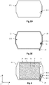
- the Figures 3B and 3C are top views of an MEA 11, on the side of the first electrode 21 for the fig.3B and on the side of the second electrode 22 for the Fig.3c .
- the anode 31 is in contact with the first face 19.1 of the electrolyte membrane 19 and positioned in the connection zone 3, and the cathode 32 is in contact with the second face 19.2 and opposite the anode 31.
- the anode 31 as the cathode 32 are distinct, and therefore electrically isolated, respectively, from the first electrode 21 and the second electrode 22.
- the electrolytic membrane 19 has a projecting portion 24 located at a border of the connection zone 3.
- the protruding portion 24 has a dimension such that it exceeds the contour of the bipolar plates 13, and is therefore accessible from from outside the stack of electrochemical cells.
- the current source comprises a first conductive track 34.1 which extends continuously on the first face 19.1 from the anode 31 with which it is in electrical contact to the portion 24 projecting. It comprises a second conductive track 34.2 which extends continuously on the second face 19.2 from the cathode 32 with which it is in electrical contact to the portion 24 projecting.
- the conductive tracks 34.1, 34.2 may take the form of a printed circuit, for example made by depositing an ink formed of a conductive material and an ionomer, advantageously having a thickness less than or equal to 10 .mu.m. This limits the local extra thicknesses that can induce leaks or inhomogeneities of mechanical stresses.
- the voltage generator can be easily connected to the conductive tracks 34.1, 34.2 to the extent that they overflow the contour of the bipolar plates.
- the 3D and 3E figures are top views of a diffusion layer 12.1 (GDL for Gas Diffusion Layer, in English) having a through hole 25.1.
- the first diffusion layer 12.1 is intended to come into contact with the first face 19.1, and to cover the active zone 2 and the connection zone 3.
- a through hole 25.1 is provided, whose contour is dimensioned to avoid contact with the edge of the anode 31.
- the conductive tracks are also electrically insulated from the diffusion layers, for example by an insulating film (not shown) forming a reinforcement of the MEA.
- an electrically insulating but porous polymeric film may be disposed between the anode 31 and the first bipolar plate 13.1.
- the film may be a polymer as marketed by the company Celgard, for example the Celgard 2500.
- Celgard for example the Celgard 2500.
- the electrical insulation between the anode 31 and the first bipolar plate 13.1 is reinforced, while preserving the fluid communication between the first circuit 18.1 and the anode 31. It is the same for the cathode 32 vis-à-vis the second bipolar plate 18.2.
- the figure 4 illustrates a top view of an MEA according to another variant, on the side of the first electrode 21, which is different from that of the fig.3B essentially in that the device 1 comprises a plurality of hydrogen sensors 30.1, 30.2, 30.3.
- Each hydrogen sensor 30.1, 30.2, 30.3 has an anode and a cathode disposed in the connection zone 3.
- the detection anodes of the different hydrogen sensors 30.1, 30.2, 30.3 are electrically isolated from each other and each placed in look at one or more channels of the first distribution circuit.
- the detection cathodes are located opposite the corresponding anodes.
- the hydrogen sensors 30.1, 30.2, 30.3 comprise first and second conductive tracks, which extend up to a portion 24 projecting from the electrolyte membrane 19.
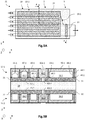
- FIGS. 5A and 5B illustrate, in top view ( 5A ) and in cross-section ( 5B ), different parts of the electrochemical device 1 according to a second variant of the embodiment.
- the bipolar plates 13 comprise a plate structured in an electrically insulating material inside which conductive lines adapted to polarize the first and second electrodes 21, 22 independently of the anode 31 and the cathode 32 of detection extend.
- the anode 31 and the detection cathode 32 are then in contact with the insulating material of the bipolar plates 13 but electrically isolated from the first and second electrodes 21, 22.
- the bipolar plates 13 are then of PCB printed circuit type.
- the Figure 5A is a top view of an AME 11 on the side of the first face 19.1 of the electrolyte membrane 19, and an example of the first distribution circuit 18.1 illustrated in dotted lines.
- the AME 11 thus comprises an electrolytic membrane 19 whose first face 19.1 is coated by the first electrode 21 which delimits the active zone 2, and by the detection anode 31 located in the connection zone 3.
- a plurality of distribution traverses the active zone 2 and, here purely illustrative, meet in the connecting zone 3 to form a homogenization zone of the flow.
- Other arrangements of the channels are of course possible.
- the distribution channels can remain separate from each other in the connection zone, or even join in groups.
- the electrolyte membrane 19 does not have a projecting portion receiving conductive tracks of the current source.
- FIG. 5B illustrates, schematically and partially, in cross-section along the sectional plane AA illustrated in FIG. 5A , an example of bipolar plates 13 of PCB type according to this second variant.
- a first zone forms the active zone 2 and a second zone, distinct from the first zone, forms the connecting zone 3, located downstream of the active zone 2 in the fluidic continuity of the first circuit. distribution 18.1, towards the first exhaust manifold 15.1 (not shown).
- the active zone 2 comprises the first electrode 21 and the second electrode 22 separated from each other by the electrolyte membrane 19, and the connection zone 3 comprises the anode 31 and the cathode 32 separated from each other. other by the same electrolyte membrane 19.
- the anode 31 and the first electrode 21 are separate from each other to avoid electrical contact, as are the cathode 32 and the second electrode 32.
- the electrolyte membrane 19 is proton conductive but insulating vis-à-vis the electrons.
- the distribution circuits 18.1, 18.2 are formed by structuring the bipolar plates.
- the first distribution circuit 18.1 is made in the same bipolar plate 13.1 having structures defining fluid distribution channels, which being adapted to apply an electrical potential to the first electrode 21 and another different electrical potential to the anode 31
- the second distribution circuit 18.2 is formed in the same bipolar plate 13.2 having structures defining fluid distribution channels, which is adapted to apply an electrical potential to the second electrode 22 and another electrical potential, possibly different, at the cathode 32.
- each bipolar plate 13.1, 13.2 is made of a PCB type PCB (Printed Circuit Board, English). It thus comprises a portion 41.1, 41.2 of an electrically insulating material, for example a ceramic, on and in which electrical lines extend.
- PCB type PCB printed Circuit Board, English
- the insulating portion 41.1 has an outer face 42e.1 and an inner face 42i.1 opposite one another along the axis d thickness of the plate 13.1.
- the inner face 42i.1 is oriented towards the first face 19.1 of the electrolyte membrane 19, and includes structures defining the distribution circuit 18.1.
- the channels of the distribution circuit 18.1 are separated in pairs and bordered by a longitudinal wall 44.1 of the insulating plate 41.1, the end of which, forming a bearing surface in contact with the first electrode 21 or the anode 31, is at least partially coated by an electrical track 45.1, 46.1 called polarization.
- polarization electrical track 45.1 contact the first electrode 21, and the polarization tracks 46.1 contact the anode 31.
- the polarization tracks 45.1 are electrically isolated from the polarization tracks 46.1.
- the polarization tracks 45.1, in contact with the first electrode 21, are connected to a so-called contact recovery electrical track 49.1 which extends on the outer face 42e.1.
- the contact recovery track 49.1 is connected to the polarization tracks 45.1 by first vias 47.1.
- the vias 47.1 are through orifices filled with an electrically conductive material, which extend along the thickness axis of the insulating plate 13.1 in the longitudinal walls 44.1.
- the polarization tracks 46.1 in contact with the detection anode 31, are connected to another electrical contact recovery track 50.1 which extends on the same external face 42e.1.
- the contact recovery track 50.1 is connected to the polarization tracks 46.1 by vias 48.1.
- the first and second electrical contact recovery tracks 49.1, 50.1 are electrically separated from each other.
- the same bipolar plate 13.1 forms a first fluid distribution circuit 18.1 for the first electrode 21 and the detection anode 31, and makes it possible to apply to these two electrodes 21, 31 different electrical potentials, one of the other.
- the second bipolar plate 13.2 may be identical or similar to the first bipolar plate 13.1 previously described. It is also possible to stack several electrode membrane assemblies along the thickness axis, the adjacent electrode membrane assemblies being separated by PCB type bipolar plates similar to those illustrated in FIG. 5B .
Landscapes
- Chemical & Material Sciences (AREA)
- Engineering & Computer Science (AREA)
- Electrochemistry (AREA)
- Chemical Kinetics & Catalysis (AREA)
- Life Sciences & Earth Sciences (AREA)
- Health & Medical Sciences (AREA)
- Organic Chemistry (AREA)
- Metallurgy (AREA)
- Materials Engineering (AREA)
- Sustainable Development (AREA)
- Manufacturing & Machinery (AREA)
- Sustainable Energy (AREA)
- General Chemical & Material Sciences (AREA)
- Physics & Mathematics (AREA)
- Analytical Chemistry (AREA)
- Pathology (AREA)
- Immunology (AREA)
- General Physics & Mathematics (AREA)
- General Health & Medical Sciences (AREA)
- Biochemistry (AREA)
- Automation & Control Theory (AREA)
- Molecular Biology (AREA)
- Medicinal Chemistry (AREA)
- Food Science & Technology (AREA)
- Combustion & Propulsion (AREA)
- Inorganic Chemistry (AREA)
- Electrolytic Production Of Non-Metals, Compounds, Apparatuses Therefor (AREA)
- Fuel Cell (AREA)
Applications Claiming Priority (1)
| Application Number | Priority Date | Filing Date | Title |
|---|---|---|---|
| FR1756603A FR3068990B1 (fr) | 2017-07-12 | 2017-07-12 | Dispositif electrochimique comportant un capteur d'hydrogene |
Publications (2)
| Publication Number | Publication Date |
|---|---|
| EP3429007A1 true EP3429007A1 (de) | 2019-01-16 |
| EP3429007B1 EP3429007B1 (de) | 2019-11-27 |
Family
ID=59974607
Family Applications (1)
| Application Number | Title | Priority Date | Filing Date |
|---|---|---|---|
| EP18182683.5A Active EP3429007B1 (de) | 2017-07-12 | 2018-07-10 | Elektrochemische vorrichtung, die einen wasserstoffsensor umfasst |
Country Status (4)
| Country | Link |
|---|---|
| US (1) | US10790524B2 (de) |
| EP (1) | EP3429007B1 (de) |
| JP (1) | JP7179513B2 (de) |
| FR (1) | FR3068990B1 (de) |
Families Citing this family (5)
| Publication number | Priority date | Publication date | Assignee | Title |
|---|---|---|---|---|
| CN112986489B (zh) * | 2019-12-14 | 2022-03-11 | 中国科学院大连化学物理研究所 | 一种阴极开放电堆单池膜电极性能测试装置 |
| US12000794B2 (en) * | 2020-12-08 | 2024-06-04 | Hyaxiom, Inc. | Hydrogen concentration sensor |
| GB2613362B (en) * | 2021-11-30 | 2025-07-23 | Bramble Energy Ltd | Electrolyser |
| GB2613360B (en) * | 2021-11-30 | 2025-02-19 | Bramble Energy Ltd | Electrolyser |
| WO2026078346A1 (en) * | 2024-10-08 | 2026-04-16 | Coventry University | An ion exchange membrane with incorporated sensing means, and fuel cell using the same |
Citations (3)
| Publication number | Priority date | Publication date | Assignee | Title |
|---|---|---|---|---|
| EP1293777A2 (de) * | 2001-09-14 | 2003-03-19 | NGK Spark Plug Company Limited | Wasserstoffsensor |
| EP1296395A1 (de) * | 2000-06-27 | 2003-03-26 | Nok Corporation | Dichtung für brennstoffzelle |
| WO2008032838A1 (en) * | 2006-09-11 | 2008-03-20 | Toyota Jidosha Kabushiki Kaisha | Fuel cell system and method of monitoring hydrogen concentration in the anode and purging the anode with hydrogen-rich gas |
Family Cites Families (6)
| Publication number | Priority date | Publication date | Assignee | Title |
|---|---|---|---|---|
| JP2001167780A (ja) | 1999-12-07 | 2001-06-22 | Mitsubishi Heavy Ind Ltd | 燃料電池用セル |
| JP2002022700A (ja) * | 2000-07-13 | 2002-01-23 | Nippon Soken Inc | 水素センサと電池の過充電・過放電検出装置および燃料電池の水素ガス漏れ検出装置 |
| JP2002310978A (ja) * | 2001-04-12 | 2002-10-23 | Ngk Spark Plug Co Ltd | 水素センサ |
| GB2507042B (en) | 2012-10-16 | 2018-07-11 | Schlumberger Holdings | Electrochemical hydrogen sensor |
| KR101646337B1 (ko) * | 2014-08-19 | 2016-08-05 | 현대자동차주식회사 | 수소센서를 이용한 연료전지용 멤브레인 결함 검사 장치 |
| FR3026231B1 (fr) * | 2014-09-19 | 2016-12-09 | Commissariat Energie Atomique | Pile a combustible destinee a la detection d’un polluant |
-
2017
- 2017-07-12 FR FR1756603A patent/FR3068990B1/fr not_active Expired - Fee Related
-
2018
- 2018-07-10 EP EP18182683.5A patent/EP3429007B1/de active Active
- 2018-07-11 JP JP2018131500A patent/JP7179513B2/ja active Active
- 2018-07-12 US US16/033,658 patent/US10790524B2/en active Active
Patent Citations (3)
| Publication number | Priority date | Publication date | Assignee | Title |
|---|---|---|---|---|
| EP1296395A1 (de) * | 2000-06-27 | 2003-03-26 | Nok Corporation | Dichtung für brennstoffzelle |
| EP1293777A2 (de) * | 2001-09-14 | 2003-03-19 | NGK Spark Plug Company Limited | Wasserstoffsensor |
| WO2008032838A1 (en) * | 2006-09-11 | 2008-03-20 | Toyota Jidosha Kabushiki Kaisha | Fuel cell system and method of monitoring hydrogen concentration in the anode and purging the anode with hydrogen-rich gas |
Also Published As
| Publication number | Publication date |
|---|---|
| JP7179513B2 (ja) | 2022-11-29 |
| EP3429007B1 (de) | 2019-11-27 |
| FR3068990A1 (fr) | 2019-01-18 |
| US10790524B2 (en) | 2020-09-29 |
| JP2019031733A (ja) | 2019-02-28 |
| FR3068990B1 (fr) | 2019-08-30 |
| US20190020044A1 (en) | 2019-01-17 |
Similar Documents
| Publication | Publication Date | Title |
|---|---|---|
| EP3429007B1 (de) | Elektrochemische vorrichtung, die einen wasserstoffsensor umfasst | |
| CA2992130C (fr) | Procedes d' (de co) electrolyse de l'eau (soec) ou de production d'electricite a haute temperature a echangeurs integres en tant qu'etages d'un empilement de reacteur (eht) ou d'une pile a combustible (sofc) | |
| CA3063286A1 (fr) | Reacteur d'electrolyse ou de co-electrolyse de l'eau (soec) ou pile a combustible (sofc) a fonctionnement sous pression et a systeme de serrage adapte a un tel fonctionnement | |
| EP3195391B1 (de) | Brennstoffzelle zur erkennung eines schadstoffes | |
| EP2788532B1 (de) | Verfahren zum betreiben eines hochtemperatur-elektrolyseurs mit einem schritt zur reduzierung des materials der kathoden | |
| EP4416317B1 (de) | Modul für ein elektrochemisches gerät mit erhöhter lebensdauer | |
| WO2018095995A1 (fr) | Cellule électrochimique rédox en flux à shunt réduit | |
| EP2692009A1 (de) | Brennstoffzelle mit protonenaustauschermembran mit erhöhter lebensdauer | |
| EP3799173B1 (de) | Brennstoffzelle mit halteplatten vom leiterplattentyp mit zu- und ableitungskammern für reaktive fluide | |
| FR3068991B1 (fr) | Systeme electrochimique d'electrolyse de l'eau comportant un assemblage membrane electrodes a portions d'electrolyse et de separation | |
| EP3813168B1 (de) | Brennstoffzelle, die für die charakterisierung mindestens eines in einem reaktiven gas enthaltenen schadstoffes geeignet ist | |
| FR3026232A1 (fr) | Plaque de guidage d’ecoulement d’un fluide pour reacteur electrochimique et ensemble comportant cette plaque | |
| EP3499625A1 (de) | Brennstoffzellensystem mit polymerelektrolytmembran und verringerter brenngas-leckage | |
| EP4576280A1 (de) | Brennstoffzelle mit einem stapel aus elektrochemischen zellen und mehreren eingangs- und ausgangsverteilern für jede reaktive flüssigkeit und für das wärmeträgermedium | |
| FR2901060A1 (fr) | "pile a combustible integree a couches laminees" | |
| EP3809504A1 (de) | Bipolare platte einer brennstoffzelle | |
| FR3053534A1 (fr) | Module de pile a combustible ayant un circuit d'hydrogene a 2 entrees | |
| EP2294647A1 (de) | Verteilerkopf für eine brennstoffzelle | |
| EP3428318B1 (de) | Elektrochemisches system und verfahren zur elektrolyse von wasser | |
| EP2826090B1 (de) | Batterie mit einer mehrzahl von batteriezellen und einer vorrichtung für jede zelle zur steuerung der spannung zwischen den klemmen dieser zelle | |
| FR3077934A1 (fr) | Pile a court-circuitage par changement de forme | |
| FR2980644A1 (fr) | Pile a combustible a haute densite d'assemblages membrane electrodes partageant une cavite fluidique commune | |
| FR3040548A1 (fr) | Pile a combustible pour optimiser l’humidification de l’air | |
| FR2903229A1 (fr) | Structure de cellule elementaire pour pile a combustible equipee de moyens d'etancheite |
Legal Events
| Date | Code | Title | Description |
|---|---|---|---|
| PUAI | Public reference made under article 153(3) epc to a published international application that has entered the european phase |
Free format text: ORIGINAL CODE: 0009012 |
|
| STAA | Information on the status of an ep patent application or granted ep patent |
Free format text: STATUS: REQUEST FOR EXAMINATION WAS MADE |
|
| 17P | Request for examination filed |
Effective date: 20180710 |
|
| AK | Designated contracting states |
Kind code of ref document: A1 Designated state(s): AL AT BE BG CH CY CZ DE DK EE ES FI FR GB GR HR HU IE IS IT LI LT LU LV MC MK MT NL NO PL PT RO RS SE SI SK SM TR |
|
| AX | Request for extension of the european patent |
Extension state: BA ME |
|
| GRAP | Despatch of communication of intention to grant a patent |
Free format text: ORIGINAL CODE: EPIDOSNIGR1 |
|
| STAA | Information on the status of an ep patent application or granted ep patent |
Free format text: STATUS: GRANT OF PATENT IS INTENDED |
|
| RIC1 | Information provided on ipc code assigned before grant |
Ipc: C25B 9/10 20060101ALI20190328BHEP Ipc: H01M 8/0444 20160101AFI20190328BHEP Ipc: C25B 9/20 20060101ALI20190328BHEP Ipc: H01M 8/0206 20160101ALN20190328BHEP Ipc: C25B 15/02 20060101ALI20190328BHEP Ipc: C25B 9/06 20060101ALI20190328BHEP Ipc: H01M 8/1018 20160101ALN20190328BHEP Ipc: G01N 33/00 20060101ALI20190328BHEP Ipc: H01M 8/0228 20160101ALN20190328BHEP Ipc: H01M 8/0221 20160101ALN20190328BHEP Ipc: C25B 1/08 20060101ALI20190328BHEP Ipc: H01M 8/0256 20160101ALN20190328BHEP |
|
| INTG | Intention to grant announced |
Effective date: 20190424 |
|
| GRAS | Grant fee paid |
Free format text: ORIGINAL CODE: EPIDOSNIGR3 |
|
| GRAA | (expected) grant |
Free format text: ORIGINAL CODE: 0009210 |
|
| STAA | Information on the status of an ep patent application or granted ep patent |
Free format text: STATUS: THE PATENT HAS BEEN GRANTED |
|
| AK | Designated contracting states |
Kind code of ref document: B1 Designated state(s): AL AT BE BG CH CY CZ DE DK EE ES FI FR GB GR HR HU IE IS IT LI LT LU LV MC MK MT NL NO PL PT RO RS SE SI SK SM TR |
|
| REG | Reference to a national code |
Ref country code: GB Ref legal event code: FG4D Free format text: NOT ENGLISH |
|
| REG | Reference to a national code |
Ref country code: CH Ref legal event code: EP |
|
| REG | Reference to a national code |
Ref country code: AT Ref legal event code: REF Ref document number: 1207742 Country of ref document: AT Kind code of ref document: T Effective date: 20191215 |
|
| REG | Reference to a national code |
Ref country code: DE Ref legal event code: R096 Ref document number: 602018001381 Country of ref document: DE |
|
| REG | Reference to a national code |
Ref country code: IE Ref legal event code: FG4D Free format text: LANGUAGE OF EP DOCUMENT: FRENCH |
|
| REG | Reference to a national code |
Ref country code: NL Ref legal event code: MP Effective date: 20191127 |
|
| REG | Reference to a national code |
Ref country code: LT Ref legal event code: MG4D |
|
| PG25 | Lapsed in a contracting state [announced via postgrant information from national office to epo] |
Ref country code: LV Free format text: LAPSE BECAUSE OF FAILURE TO SUBMIT A TRANSLATION OF THE DESCRIPTION OR TO PAY THE FEE WITHIN THE PRESCRIBED TIME-LIMIT Effective date: 20191127 Ref country code: SE Free format text: LAPSE BECAUSE OF FAILURE TO SUBMIT A TRANSLATION OF THE DESCRIPTION OR TO PAY THE FEE WITHIN THE PRESCRIBED TIME-LIMIT Effective date: 20191127 Ref country code: FI Free format text: LAPSE BECAUSE OF FAILURE TO SUBMIT A TRANSLATION OF THE DESCRIPTION OR TO PAY THE FEE WITHIN THE PRESCRIBED TIME-LIMIT Effective date: 20191127 Ref country code: BG Free format text: LAPSE BECAUSE OF FAILURE TO SUBMIT A TRANSLATION OF THE DESCRIPTION OR TO PAY THE FEE WITHIN THE PRESCRIBED TIME-LIMIT Effective date: 20200227 Ref country code: GR Free format text: LAPSE BECAUSE OF FAILURE TO SUBMIT A TRANSLATION OF THE DESCRIPTION OR TO PAY THE FEE WITHIN THE PRESCRIBED TIME-LIMIT Effective date: 20200228 Ref country code: NO Free format text: LAPSE BECAUSE OF FAILURE TO SUBMIT A TRANSLATION OF THE DESCRIPTION OR TO PAY THE FEE WITHIN THE PRESCRIBED TIME-LIMIT Effective date: 20200227 Ref country code: NL Free format text: LAPSE BECAUSE OF FAILURE TO SUBMIT A TRANSLATION OF THE DESCRIPTION OR TO PAY THE FEE WITHIN THE PRESCRIBED TIME-LIMIT Effective date: 20191127 Ref country code: LT Free format text: LAPSE BECAUSE OF FAILURE TO SUBMIT A TRANSLATION OF THE DESCRIPTION OR TO PAY THE FEE WITHIN THE PRESCRIBED TIME-LIMIT Effective date: 20191127 |
|
| PG25 | Lapsed in a contracting state [announced via postgrant information from national office to epo] |
Ref country code: IS Free format text: LAPSE BECAUSE OF FAILURE TO SUBMIT A TRANSLATION OF THE DESCRIPTION OR TO PAY THE FEE WITHIN THE PRESCRIBED TIME-LIMIT Effective date: 20200327 Ref country code: HR Free format text: LAPSE BECAUSE OF FAILURE TO SUBMIT A TRANSLATION OF THE DESCRIPTION OR TO PAY THE FEE WITHIN THE PRESCRIBED TIME-LIMIT Effective date: 20191127 Ref country code: RS Free format text: LAPSE BECAUSE OF FAILURE TO SUBMIT A TRANSLATION OF THE DESCRIPTION OR TO PAY THE FEE WITHIN THE PRESCRIBED TIME-LIMIT Effective date: 20191127 |
|
| PG25 | Lapsed in a contracting state [announced via postgrant information from national office to epo] |
Ref country code: AL Free format text: LAPSE BECAUSE OF FAILURE TO SUBMIT A TRANSLATION OF THE DESCRIPTION OR TO PAY THE FEE WITHIN THE PRESCRIBED TIME-LIMIT Effective date: 20191127 |
|
| PG25 | Lapsed in a contracting state [announced via postgrant information from national office to epo] |
Ref country code: PT Free format text: LAPSE BECAUSE OF FAILURE TO SUBMIT A TRANSLATION OF THE DESCRIPTION OR TO PAY THE FEE WITHIN THE PRESCRIBED TIME-LIMIT Effective date: 20200419 Ref country code: CZ Free format text: LAPSE BECAUSE OF FAILURE TO SUBMIT A TRANSLATION OF THE DESCRIPTION OR TO PAY THE FEE WITHIN THE PRESCRIBED TIME-LIMIT Effective date: 20191127 Ref country code: EE Free format text: LAPSE BECAUSE OF FAILURE TO SUBMIT A TRANSLATION OF THE DESCRIPTION OR TO PAY THE FEE WITHIN THE PRESCRIBED TIME-LIMIT Effective date: 20191127 Ref country code: RO Free format text: LAPSE BECAUSE OF FAILURE TO SUBMIT A TRANSLATION OF THE DESCRIPTION OR TO PAY THE FEE WITHIN THE PRESCRIBED TIME-LIMIT Effective date: 20191127 Ref country code: ES Free format text: LAPSE BECAUSE OF FAILURE TO SUBMIT A TRANSLATION OF THE DESCRIPTION OR TO PAY THE FEE WITHIN THE PRESCRIBED TIME-LIMIT Effective date: 20191127 Ref country code: DK Free format text: LAPSE BECAUSE OF FAILURE TO SUBMIT A TRANSLATION OF THE DESCRIPTION OR TO PAY THE FEE WITHIN THE PRESCRIBED TIME-LIMIT Effective date: 20191127 |
|
| REG | Reference to a national code |
Ref country code: DE Ref legal event code: R097 Ref document number: 602018001381 Country of ref document: DE |
|
| PG25 | Lapsed in a contracting state [announced via postgrant information from national office to epo] |
Ref country code: SM Free format text: LAPSE BECAUSE OF FAILURE TO SUBMIT A TRANSLATION OF THE DESCRIPTION OR TO PAY THE FEE WITHIN THE PRESCRIBED TIME-LIMIT Effective date: 20191127 Ref country code: SK Free format text: LAPSE BECAUSE OF FAILURE TO SUBMIT A TRANSLATION OF THE DESCRIPTION OR TO PAY THE FEE WITHIN THE PRESCRIBED TIME-LIMIT Effective date: 20191127 |
|
| REG | Reference to a national code |
Ref country code: AT Ref legal event code: MK05 Ref document number: 1207742 Country of ref document: AT Kind code of ref document: T Effective date: 20191127 |
|
| PLBE | No opposition filed within time limit |
Free format text: ORIGINAL CODE: 0009261 |
|
| STAA | Information on the status of an ep patent application or granted ep patent |
Free format text: STATUS: NO OPPOSITION FILED WITHIN TIME LIMIT |
|
| 26N | No opposition filed |
Effective date: 20200828 |
|
| PG25 | Lapsed in a contracting state [announced via postgrant information from national office to epo] |
Ref country code: SI Free format text: LAPSE BECAUSE OF FAILURE TO SUBMIT A TRANSLATION OF THE DESCRIPTION OR TO PAY THE FEE WITHIN THE PRESCRIBED TIME-LIMIT Effective date: 20191127 Ref country code: AT Free format text: LAPSE BECAUSE OF FAILURE TO SUBMIT A TRANSLATION OF THE DESCRIPTION OR TO PAY THE FEE WITHIN THE PRESCRIBED TIME-LIMIT Effective date: 20191127 Ref country code: PL Free format text: LAPSE BECAUSE OF FAILURE TO SUBMIT A TRANSLATION OF THE DESCRIPTION OR TO PAY THE FEE WITHIN THE PRESCRIBED TIME-LIMIT Effective date: 20191127 |
|
| PG25 | Lapsed in a contracting state [announced via postgrant information from national office to epo] |
Ref country code: IT Free format text: LAPSE BECAUSE OF FAILURE TO SUBMIT A TRANSLATION OF THE DESCRIPTION OR TO PAY THE FEE WITHIN THE PRESCRIBED TIME-LIMIT Effective date: 20191127 |
|
| PG25 | Lapsed in a contracting state [announced via postgrant information from national office to epo] |
Ref country code: MC Free format text: LAPSE BECAUSE OF FAILURE TO SUBMIT A TRANSLATION OF THE DESCRIPTION OR TO PAY THE FEE WITHIN THE PRESCRIBED TIME-LIMIT Effective date: 20191127 |
|
| REG | Reference to a national code |
Ref country code: BE Ref legal event code: MM Effective date: 20200731 |
|
| PG25 | Lapsed in a contracting state [announced via postgrant information from national office to epo] |
Ref country code: LU Free format text: LAPSE BECAUSE OF NON-PAYMENT OF DUE FEES Effective date: 20200710 |
|
| PG25 | Lapsed in a contracting state [announced via postgrant information from national office to epo] |
Ref country code: BE Free format text: LAPSE BECAUSE OF NON-PAYMENT OF DUE FEES Effective date: 20200731 |
|
| PG25 | Lapsed in a contracting state [announced via postgrant information from national office to epo] |
Ref country code: IE Free format text: LAPSE BECAUSE OF NON-PAYMENT OF DUE FEES Effective date: 20200710 |
|
| REG | Reference to a national code |
Ref country code: CH Ref legal event code: PL |
|
| PG25 | Lapsed in a contracting state [announced via postgrant information from national office to epo] |
Ref country code: LI Free format text: LAPSE BECAUSE OF NON-PAYMENT OF DUE FEES Effective date: 20210731 Ref country code: CH Free format text: LAPSE BECAUSE OF NON-PAYMENT OF DUE FEES Effective date: 20210731 |
|
| PG25 | Lapsed in a contracting state [announced via postgrant information from national office to epo] |
Ref country code: TR Free format text: LAPSE BECAUSE OF FAILURE TO SUBMIT A TRANSLATION OF THE DESCRIPTION OR TO PAY THE FEE WITHIN THE PRESCRIBED TIME-LIMIT Effective date: 20191127 Ref country code: MT Free format text: LAPSE BECAUSE OF FAILURE TO SUBMIT A TRANSLATION OF THE DESCRIPTION OR TO PAY THE FEE WITHIN THE PRESCRIBED TIME-LIMIT Effective date: 20191127 Ref country code: CY Free format text: LAPSE BECAUSE OF FAILURE TO SUBMIT A TRANSLATION OF THE DESCRIPTION OR TO PAY THE FEE WITHIN THE PRESCRIBED TIME-LIMIT Effective date: 20191127 |
|
| PG25 | Lapsed in a contracting state [announced via postgrant information from national office to epo] |
Ref country code: MK Free format text: LAPSE BECAUSE OF FAILURE TO SUBMIT A TRANSLATION OF THE DESCRIPTION OR TO PAY THE FEE WITHIN THE PRESCRIBED TIME-LIMIT Effective date: 20191127 |
|
| GBPC | Gb: european patent ceased through non-payment of renewal fee |
Effective date: 20220710 |
|
| PG25 | Lapsed in a contracting state [announced via postgrant information from national office to epo] |
Ref country code: GB Free format text: LAPSE BECAUSE OF NON-PAYMENT OF DUE FEES Effective date: 20220710 |
|
| PGFP | Annual fee paid to national office [announced via postgrant information from national office to epo] |
Ref country code: DE Payment date: 20250722 Year of fee payment: 8 |
|
| PGFP | Annual fee paid to national office [announced via postgrant information from national office to epo] |
Ref country code: FR Payment date: 20250722 Year of fee payment: 8 |