EP3429218B1 - Fausse enceinte de cadre de distribution intermédiaire à colonne - Google Patents
Fausse enceinte de cadre de distribution intermédiaire à colonne Download PDFInfo
- Publication number
- EP3429218B1 EP3429218B1 EP18183451.6A EP18183451A EP3429218B1 EP 3429218 B1 EP3429218 B1 EP 3429218B1 EP 18183451 A EP18183451 A EP 18183451A EP 3429218 B1 EP3429218 B1 EP 3429218B1
- Authority
- EP
- European Patent Office
- Prior art keywords
- assembly
- vertical
- vertical column
- column assembly
- internal structure
- Prior art date
- Legal status (The legal status is an assumption and is not a legal conclusion. Google has not performed a legal analysis and makes no representation as to the accuracy of the status listed.)
- Active
Links
Images





Classifications
-
- H—ELECTRICITY
- H04—ELECTRIC COMMUNICATION TECHNIQUE
- H04Q—SELECTING
- H04Q1/00—Details of selecting apparatus or arrangements
- H04Q1/02—Constructional details
- H04Q1/025—Cabinets
-
- H—ELECTRICITY
- H05—ELECTRIC TECHNIQUES NOT OTHERWISE PROVIDED FOR
- H05K—PRINTED CIRCUITS; CASINGS OR CONSTRUCTIONAL DETAILS OF ELECTRIC APPARATUS; MANUFACTURE OF ASSEMBLAGES OF ELECTRICAL COMPONENTS
- H05K5/00—Casings, cabinets or drawers for electric apparatus
- H05K5/10—Casings, cabinets or drawers for electric apparatus comprising several parts forming a closed casing
-
- H—ELECTRICITY
- H04—ELECTRIC COMMUNICATION TECHNIQUE
- H04Q—SELECTING
- H04Q1/00—Details of selecting apparatus or arrangements
- H04Q1/02—Constructional details
- H04Q1/08—Frames or mounting racks for relays; Accessories therefor
-
- H—ELECTRICITY
- H05—ELECTRIC TECHNIQUES NOT OTHERWISE PROVIDED FOR
- H05K—PRINTED CIRCUITS; CASINGS OR CONSTRUCTIONAL DETAILS OF ELECTRIC APPARATUS; MANUFACTURE OF ASSEMBLAGES OF ELECTRICAL COMPONENTS
- H05K5/00—Casings, cabinets or drawers for electric apparatus
- H05K5/02—Details
- H05K5/0213—Venting apertures; Constructional details thereof
-
- H—ELECTRICITY
- H05—ELECTRIC TECHNIQUES NOT OTHERWISE PROVIDED FOR
- H05K—PRINTED CIRCUITS; CASINGS OR CONSTRUCTIONAL DETAILS OF ELECTRIC APPARATUS; MANUFACTURE OF ASSEMBLAGES OF ELECTRICAL COMPONENTS
- H05K5/00—Casings, cabinets or drawers for electric apparatus
- H05K5/02—Details
- H05K5/03—Covers
-
- H—ELECTRICITY
- H05—ELECTRIC TECHNIQUES NOT OTHERWISE PROVIDED FOR
- H05K—PRINTED CIRCUITS; CASINGS OR CONSTRUCTIONAL DETAILS OF ELECTRIC APPARATUS; MANUFACTURE OF ASSEMBLAGES OF ELECTRICAL COMPONENTS
- H05K7/00—Constructional details common to different types of electric apparatus
- H05K7/14—Mounting supporting structure in casing or on frame or rack
- H05K7/1485—Servers; Data center rooms, e.g. 19-inch computer racks
- H05K7/1488—Cabinets therefor, e.g. chassis or racks or mechanical interfaces between blades and support structures
-
- H—ELECTRICITY
- H05—ELECTRIC TECHNIQUES NOT OTHERWISE PROVIDED FOR
- H05K—PRINTED CIRCUITS; CASINGS OR CONSTRUCTIONAL DETAILS OF ELECTRIC APPARATUS; MANUFACTURE OF ASSEMBLAGES OF ELECTRICAL COMPONENTS
- H05K7/00—Constructional details common to different types of electric apparatus
- H05K7/18—Construction of rack or frame
-
- H—ELECTRICITY
- H05—ELECTRIC TECHNIQUES NOT OTHERWISE PROVIDED FOR
- H05K—PRINTED CIRCUITS; CASINGS OR CONSTRUCTIONAL DETAILS OF ELECTRIC APPARATUS; MANUFACTURE OF ASSEMBLAGES OF ELECTRICAL COMPONENTS
- H05K7/00—Constructional details common to different types of electric apparatus
- H05K7/20—Modifications to facilitate cooling, ventilating, or heating
- H05K7/20709—Modifications to facilitate cooling, ventilating, or heating for server racks or cabinets; for data centers, e.g. 19-inch computer racks
- H05K7/20718—Forced ventilation of a gaseous coolant
- H05K7/20736—Forced ventilation of a gaseous coolant within cabinets for removing heat from server blades
Definitions
- the present invention relates to an enclosure, and more particularly, to an enclosure for encasing and securing rack mountable equipment.
- IDF Intermediate Distribution Frame
- MDF Main Distribution Frame
- Some office environments lack a raised floor and drop ceiling, or have a drop ceiling with limited space, or have limited floor space to accommodate a telecommunications closet. It may also be preferable to have networking equipment installed in a more accessible area other than the floor or ceiling.
- Current solutions exist for housing and connecting cabling and active networking equipment within the office area or workspace.
- the current solutions include free standing cabinets or wall mounted cabinets.
- the free-standing cabinet and wall mount cabinets are bulky, do not isolate unwanted noise, and do not integrate well with the aesthetics or architectural design of an office interior.
- Many office environments hide electrical cabling, plumbing, or other building infrastructure components within faux vertical columns. These columns are typically constructed of drywall or wood and may not allow easy access to the components inside.
- the current faux vertical columns are not designed to house active networking equipment due to a lack of ventilation and an access door.
- EP 1 835 583 A2 describes a network cabinet comprising a support frame and a threshold associated with the support frame.
- a door comprising first and second lateral sides is mounted to the support frame through a hinge pin.
- the hinge pin is moveable between retracted and extended positions and is positioned closer to the first lateral side of the door than the second lateral side.
- a bearing surface is also associated with the support frame and is aligned with the hinge pin such that the door elevated relative to the threshold with the hinge pin in the extended position and in contact with the bearing surface.
- WO 2009/058928 A1 describes a patching system that includes network equipment in a cabinet; a first patch panel cabinet; a second patch panel cabinet; a vertical patch panel mounted between the first patch panel cabinet and the second patch panel cabinet, the vertical patch panel having telecommunications connectors mounted therein; and a vertical cable manager mounted adjacent to one of the first patch panel cabinet and the second patch panel cabinet.
- US2014345238 describes an enclosure which has a perforated front door with a replaceable filter, and a perforated rear side allowing air to flow through the enclosure.
- the enclosure also has mounting brackets for heat generating elements, such as line cards or other rack mounted electronics. A fan draws air through the perforated front door, though the filter, and across the heat generating elements.
- Side brushes are disposed on a side wall near the front of the enclosure, which allow any cables attached to the heat generating elements to exit the enclosure.
- the front door is removable, opening up one side of the side brushes and allowing the cables to slide in the side brushes while still connected to the heat generating elements.
- a vertical column assembly for supporting cabling and active network equipment as defined in claim 1.
- a vertical column assembly includes an intermediate distribution frame enclosure with an internal structure that supports cabling and active network equipment.
- the vertical column assembly includes side panels, door assemblies and a top cover assembly. The internal structure is hidden by the side panels, the door assemblies, and the top cover assembly.
- an enclosure assembly that encases network equipment installed in an intermediate distribution frame within an office workspace.
- the enclosure assembly includes an intermediate distribution frame enclosure with an internal structure having network equipment mounted therein.
- the internal structure has at least one mounting bracket positioned at a corner of the internal structure.
- the enclosure assembly also includes at least one door assembly, side panels mounted to the internal structure, and a top cover assembly covering a top of the internal structure.
- the door assembly is mounted to the at least one mounting bracket. That door assembly includes a perforated vent to ventilate heat generate by the network equipment.
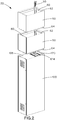
- FIG. 1 illustrates a column 20 that includes a network cable bundle 30, vertical extensions 50, and a faux column IDF enclosure 100.
- Fig. 2 is an exploded view of the column.
- the network cable bundle 30 passes through the vertical extensions 50 before entering the top of the faux column IDF enclosure 100.
- the vertical extensions 50 hide the network cable bundle 30.
- the vertical extensions 50 are stackable and can be used in any non-limiting quantity, including none, as needed to extend to the ceiling and hide the full vertical length of the network cable bundle 30.
- Each vertical extension 50 is a hollow rectangular shell 60 with an upper indentation or receiving area 62 and a lower projection 64 that extend the perimeter of the shell 60.
- the lowest projection 64 is secured to the faux column IDF enclosure 100 with bolts (not shown).
- the remainder of the column 20 is created by stacking one vertical extension 50 at a time, as needed. Threaded rods (not shown) secure the uppermost vertical extension 50 to the ceiling to provide stability to the column 20, as necessary.
- the outer appearance of the vertical extensions 50 matches the faux column IDF enclosure 100 to provide a column 20 with continuous lines throughout the height of the column 20.
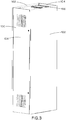
- FIG. 3 illustrates the faux column IDF enclosure 100 with side panels 102, door assemblies 104 and a top cover assembly 106.
- the side panels 102, door assemblies 104, and vertical extensions 50 may be painted to match the aesthetics of the office interior.
- the side panels 102 do not present any lines, bends, or holes on the side surface of the faux column IDF enclosure 100 to contribute to a plain and flat appearance.
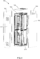
- FIG. 4 illustrates the faux column IDF enclosure 100 with the side panels 102 and the door assemblies 104 being removed to illustrate the internal structure 108 of the faux column IDF enclosure 100.
- the internal structure 108 is hidden from view which contributes to the plain appearance of the faux column IDF enclosure 100.
- the internal structure 108 contains network equipment 200 that is mounted vertically. The network equipment 200 is completely enclosed by the side panels 102, the door assemblies 104, the top cover assembly 106, and the room floor to isolate the noise.
- FIG. 5 is a detailed view of the bottom section of the internal structure 108 of FIG. 4 .
- the internal structure 108 includes a support frame assembly 110 with left mounting brackets 112 and right mounting brackets 116 attached at the corners of the support frame assembly 110.
- the internal structure 108 also includes vertical panel supports 120 extending the height of the internal structure 108 and lower panel supports 122 extending the width of the internal structure 108.
- FIG. 6 illustrates the support frame assembly 110 with the left mounting bracket 112, the right mounting bracket 116, the vertical panel supports 120 and the lower panel supports 122 removed.
- the side panels 102 are secured to the left and right mounting brackets 112, 116, respectively, with screws (not illustrated). The attachment points of the side panels 102 are hidden from view when the door assemblies 104 are in the closed position to contribute to a plain exterior appearance.
- the side panels 102 are also adhered to the top cover assembly 106, vertical panel supports 120, lower panel supports 122 and the support frame assembly 110 via adhesive foam tape to prevent audible vibration and eliminate the need for welding.
- Vertical panel supports 120 and lower panels supports 122 provide rigidity to the side panels 102 when adhered enabling the side panels 102 to maintain their flat shape and achieve sufficient strength without adding visible bends or other features that would compromise their plain appearance.
- FIG. 7 illustrates an exploded view of the support frame assembly 110.
- the support frame assembly 110 includes rack side weldments 124, a left vertical rail 126, a right vertical rail 130, horizontal rails 134, and tie brackets 140.
- the support frame assembly 110 rests on the floor and is secured via bolts (not illustrated) through holes 142 in the tie brackets 140.
- FIG. 8 illustrates the front of an assembled support frame assembly 110.
- the support frame assembly 110 includes a number of equipment mounting areas 144.
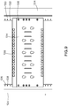
- FIG. 9 is a detailed view of one of the horizontal rails 134 of the support frame assembly 110 with a plurality of clearance holes or mounting holes 136 which are spaced per the vertical hole spacing standard of EIA-310.
- FIG. 9 also illustrates the left vertical rail 126 and the right vertical rail 130 with a plurality of threaded holes 128, 132, respectively, which are also spaced per the vertical hole spacing standard of EIA-310.
- the clearance holes 136 of the horizontal rail 134 align with the plurality of threaded holes 128, 132 in the left and right vertical rails 126, 130, respectively. Screws (not illustrated) attach the horizontal rails 134 to the left and right vertical rails 126, 130.
- Each horizontal rail 134 includes a plurality of cage nut holes 138 which are also spaced per the vertical hole spacing standard of EIA-310.
- the left and right vertical rails 126, 130 support rack-mountable equipment 200 vertically, at a right angle to the intended, typical equipment mounting orientation.
- the vertical distance between the cage nut holes 138 and the clearance holes 136 allows multiple identical horizontal rails 134 to attach along the left vertical rail 126 and the right vertical rail 130 such that the vertical spacing of opposing cage nut holes 138 on adjacent horizontal rails 134 equals the EIA-310 rail to rail spacing standard (18.312 inches, center to center).
- the quantity of cage nut holes 138 allows for 6 rack mount units (RU) of capacity (per EIA-310) within each equipment mounting area 144, totaling 18 RU capacity for the faux column IDF enclosure 100.
- the vertical orientation of network equipment 200 allows rack side weldments 124 to be spaced closer together horizontally than typical four-posts racks.
- the existing rack side weldments 124 allow left vertical rail 126 and right vertical rail 130 to translate forward and backward thus allowing the position of horizontal rails 134 to be adjusted by the end user by translating all connected rail components as a singular unit.
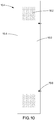
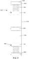
- FIGS. 10 and 11 illustrate the door assembly 104.
- the door assembly 104 includes a main body 150 with perforated vents 152, a door hinge 154, and keyed cam-latches 156.
- the inside of the main body 150 of the door includes end braces 158, middle braces 160, and rubber bumpers 162.
- the door hinge 154 attaches with screws to either left mounting bracket 112 or right mounting bracket 116 by rotating the door assembly 104 180 degrees to allow the main body 150 to swing open in the direction desired by the end user.
- the left mounting brackets 112 and the right mounting brackets 116 have slots 114, 118, respectively, that are engaged by keyed cam-latches 156 to hold the door assembly 104 in the closed position when mounted in either orientation.
- Rubber bumpers 162 contact support frame assembly 110 while door assembly 104 is in the closed positioned to prevent over rotation of the door hinge 154 while the door is closed and to prevent audible vibration.
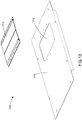
- FIGS. 12-13 illustrate the top cover assembly 106 of the faux column IDF enclosure 100.
- the top cover assembly 106 includes a top cover panel 170 and a brushed pass through assembly 174.
- the top cover panel 170 includes a centered entry hole 172.
- the entry hole 172 is designed to receive the brushed pass through assembly 174.
- a cable bundle 30 passes through the brushed pass-through assembly 174 and through the entry hole 172 in the top cover panel 170 to enter the faux column IDF enclosure 100.
- the brushed pass through assembly 174 blocks air flow around the cable bundle 30 so air flow can only enter or exit the faux column IDF enclosure 100 through the perforated vents 152.
- FIG. 14 illustrates the faux column IDF enclosure 100 with the rear door assembly 104 opened.
- An exhaust fan 164 is secured to the rear door main body 150 to evacuate the hot air generated by the network equipment 200 out of the faux column IDF enclosure 100 through the upper perforated vent 152. Cooler air enters the faux column IDF enclosure 100 through the perforated vents 152 on the front door assembly 104 and the remaining perforated vent 152 on the rear door assembly 104.
- the vertical standing lockable faux column IDF enclosure of the present invention encases and secures rack-mountable networking equipment and network cabling while ventilating the heat generated by the equipment.
- the networking equipment is vertically mounted inside the faux column IDF enclosure to allow for a smaller overall width as compared to existing rack and cabinet products.
- the faux column IDF enclosure resembles a rectangular building column with a plain, flat, and rectangular appearance having minimal lines and features visible from the exterior.
Landscapes
- Engineering & Computer Science (AREA)
- Microelectronics & Electronic Packaging (AREA)
- Computer Networks & Wireless Communication (AREA)
- Computer Hardware Design (AREA)
- General Engineering & Computer Science (AREA)
- Physics & Mathematics (AREA)
- Thermal Sciences (AREA)
- Patch Boards (AREA)
Claims (12)
- Ensemble colonne vertical pour supporter des équipements de câblage et de réseau actif, l'ensemble colonne vertical comprenant :une enceinte de cadre de distribution intermédiaire (100) avec une structure interne (108) ; des panneaux latéraux (102) ; des ensembles portes (104) ; et un ensemble couvercle supérieur (106) ; dans lequel la structure interne (108) est cachée par les panneaux latéraux (102), les ensembles portes (104), et l'ensemble couvercle supérieur (106) ;l'ensemble étant caractérisé en ce que :les ensembles portes (104) incluent des charnières de porte (154) fixées à une des ferrures de montage (112, 116) et un corps principal (150) avec des orifices d'évacuation perforés (152) pour la ventilation de la chaleur générée par l'équipement de réseau (200) ; eten ce que les ensembles portes (104) comprennent en outre un ventilateur d'extraction (164) fixé au corps principal (150), le ventilateur d'extraction (164) étant agencé pour évacuer l'air chaud généré par l'équipement de réseau (200).
- Ensemble colonne vertical selon la revendication 1, dans lequel la structure interne (108) inclut un ensemble cadre de support (110) avec des ferrures de montage (112, 116) attachées au niveau de coins de l'ensemble cadre de support (110) ; dans lequel les panneaux latéraux (102) sont attachés aux ferrures de montage (112, 116).
- Ensemble colonne vertical selon la revendication 1, dans lequel le corps principal (150) des ensembles portes (104) inclut des étais d'extrémité (158), des étais médians (160), et des amortisseurs en caoutchouc (162) pour empêcher la rotation excessive des ensembles portes (104).
- Ensemble colonne vertical selon une quelconque revendication précédente, dans lequel l'ensemble couvercle supérieur (106) inclut un trou d'entrée (172) pour le câblage et un ensemble passage à balai (174) positionné sur le trou d'entrée (172) pour bloquer l'écoulement d'air autour du câblage.
- Ensemble colonne vertical selon l'une quelconque des revendications 2 à 4, dans lequel l'ensemble cadre de support (110) comprend en outre des ensembles soudés latéraux de bâti (124), des rails verticaux (126, 130), des rails horizontaux (134), et des ferrures d'attache (140), dans lequel les ensembles soudés latéraux de bâti (124) permettent aux rails verticaux (126, 130) de se translater vers l'avant et vers l'arrière pour permettre le positionnement ajustable des rails horizontaux (134).
- Ensemble colonne vertical selon la revendication 5, dans lequel l'ensemble cadre de support (110) inclut des zones de montage définies par les rails horizontaux (134) et les rails verticaux (126, 130) pour recevoir l'équipement de réseau (200) dans une orientation verticale.
- Ensemble colonne vertical selon l'une quelconque des revendications 2 à 6, dans lequel la structure interne comprend en outre un support de panneau vertical (120) s'étendant sur la hauteur de la structure interne et des supports de panneau inférieurs (122) s'étendant sur la largeur de la structure interne.
- Ensemble colonne vertical selon la revendication 7, dans lequel les panneaux latéraux (102) adhèrent à l'ensemble couvercle supérieur (106), aux supports de panneau verticaux (120), aux supports de panneau inférieurs (122), et à l'ensemble cadre de support (110) avec une bande en mousse adhésive pour empêcher la vibration audible.
- Ensemble colonne vertical selon la revendication 8, dans lequel les supports de panneau verticaux et les supports de panneau inférieurs (122) fournissent une rigidité aux panneaux latéraux (102) permettant aux panneaux latéraux (102) de maintenir leur forme plate et d'obtenir une résistance suffisante.
- Ensemble colonne vertical selon une quelconque revendication précédente, comprenant en outre au moins une extension verticale (50) pour cacher une longueur entière du câblage.
- Ensemble colonne vertical selon la revendication 10, dans lequel l'au moins une extension verticale (50) a une enveloppe rectangulaire creuse, une zone de réception supérieure (62) qui s'étend sur un périmètre de l'enveloppe, et une saillie inférieure (64) qui s'étend sur un périmètre de l'enveloppe.
- Ensemble colonne vertical selon la revendication 11, dans lequel la saillie inférieure (64) est fixée à l'enceinte de cadre de distribution intermédiaire (100).
Applications Claiming Priority (2)
| Application Number | Priority Date | Filing Date | Title |
|---|---|---|---|
| US201762532479P | 2017-07-14 | 2017-07-14 | |
| US16/028,506 US20190021178A1 (en) | 2017-07-14 | 2018-07-06 | Faux Column Intermediate Distribution Frame Enclosure |
Publications (2)
| Publication Number | Publication Date |
|---|---|
| EP3429218A1 EP3429218A1 (fr) | 2019-01-16 |
| EP3429218B1 true EP3429218B1 (fr) | 2020-04-01 |
Family
ID=63077692
Family Applications (1)
| Application Number | Title | Priority Date | Filing Date |
|---|---|---|---|
| EP18183451.6A Active EP3429218B1 (fr) | 2017-07-14 | 2018-07-13 | Fausse enceinte de cadre de distribution intermédiaire à colonne |
Country Status (2)
| Country | Link |
|---|---|
| US (2) | US20190021178A1 (fr) |
| EP (1) | EP3429218B1 (fr) |
Cited By (2)
| Publication number | Priority date | Publication date | Assignee | Title |
|---|---|---|---|---|
| US11266028B2 (en) | 2017-07-14 | 2022-03-01 | Panduit Corp. | Faux column intermediate distribution frame enclosure |
| US20230073519A1 (en) * | 2021-09-08 | 2023-03-09 | Vertiv Corporation | Electronic equipment enclosure with enhanced mounting flexibility |
Families Citing this family (7)
| Publication number | Priority date | Publication date | Assignee | Title |
|---|---|---|---|---|
| USD882829S1 (en) * | 2017-04-24 | 2020-04-28 | Bouchard Communications, Inc. | Cover for electronic system |
| CN111629543B (zh) * | 2019-02-28 | 2024-07-05 | 施耐德电气It公司 | 用于设备机架的盖组件 |
| US11943891B2 (en) * | 2020-05-08 | 2024-03-26 | Gulfstream Aerospace Corporation | Method and apparatus for electronics rack assembly and transportation |
| US11998112B2 (en) | 2020-05-20 | 2024-06-04 | Hoffman Enclosures, Inc. | Internal side panel for enclosures |
| CN112135473B (zh) * | 2020-09-06 | 2021-10-26 | 苏州浪潮智能科技有限公司 | 一种模块化运输机柜 |
| CN113133259B (zh) * | 2021-03-03 | 2023-01-10 | 中天宽带技术有限公司 | 通信机柜 |
| US12550285B2 (en) * | 2023-05-26 | 2026-02-10 | Dell Products L.P. | Sliding top panel for a server rack |
Citations (1)
| Publication number | Priority date | Publication date | Assignee | Title |
|---|---|---|---|---|
| US20140345238A1 (en) * | 2013-05-23 | 2014-11-27 | Cisco Technology, Inc. | Air Filtration and Visual Barrier for Enclosure with Front-To-Back Airflow |
Family Cites Families (72)
| Publication number | Priority date | Publication date | Assignee | Title |
|---|---|---|---|---|
| US5286919A (en) * | 1991-06-28 | 1994-02-15 | Digital Equipment Corporation | Computer cable management system |
| US6089892A (en) * | 1998-04-27 | 2000-07-18 | Haworth, Inc. | Telecommunications cabling arrangement |
| US6164639A (en) | 1998-09-11 | 2000-12-26 | Hewlett-Packard Company | Apparatus and method for measuring a dimension of an object |
| US6164369A (en) * | 1999-07-13 | 2000-12-26 | Lucent Technologies Inc. | Door mounted heat exchanger for outdoor equipment enclosure |
| US7504581B2 (en) * | 2006-03-13 | 2009-03-17 | Panduit Corp. | Network cabinet |
| US6185098B1 (en) | 2000-01-31 | 2001-02-06 | Chatsworth Products, Inc. | Co-location server cabinet |
| US6574970B2 (en) * | 2000-02-18 | 2003-06-10 | Toc Technology, Llc | Computer room air flow method and apparatus |
| US6293637B1 (en) * | 2000-05-12 | 2001-09-25 | Amco Engineering Co. | Earthquake-resistant electronic equipment frame |
| US20040183409A1 (en) * | 2001-01-23 | 2004-09-23 | Cooper Technologies Company | Electrical equipment enclosure |
| US6867966B2 (en) * | 2002-05-31 | 2005-03-15 | Verari Systems, Inc. | Method and apparatus for rack mounting computer components |
| US6826036B2 (en) * | 2002-06-28 | 2004-11-30 | Hewlett-Packard Development Company, L.P. | Modular power distribution system for use in computer equipment racks |
| US6889752B2 (en) * | 2002-07-11 | 2005-05-10 | Avaya Technology Corp. | Systems and methods for weatherproof cabinets with multiple compartment cooling |
| US7112131B2 (en) | 2003-05-13 | 2006-09-26 | American Power Conversion Corporation | Rack enclosure |
| US7033267B2 (en) | 2003-05-13 | 2006-04-25 | American Power Conversion Corporation | Rack enclosure |
| US7049521B2 (en) * | 2004-03-30 | 2006-05-23 | Panduit Corp. | Flexible wiring duct |
| US7460375B2 (en) * | 2004-05-07 | 2008-12-02 | Rackable Systems, Inc. | Interface assembly |
| US7578733B2 (en) | 2004-07-27 | 2009-08-25 | Hewlett-Packard Development Company, L.P. | Enclosures with redundant fans in doors with interlocks |
| US20060043031A1 (en) * | 2004-08-26 | 2006-03-02 | Cooper Technologies Company | Electronic equipment rack |
| US7417188B2 (en) * | 2004-09-13 | 2008-08-26 | Leviton Manufacturing Co., Inc. | Cable management system |
| JP4312235B2 (ja) * | 2004-11-16 | 2009-08-12 | 富士通株式会社 | 通信装置及び架構造 |
| US7144320B2 (en) * | 2004-12-29 | 2006-12-05 | Turek James R | Air distribution arrangement for rack-mounted equipment |
| US20060269207A1 (en) * | 2005-05-31 | 2006-11-30 | Cablecom, Llc | Information technology communications cabinet for electrical substation communications |
| US7542287B2 (en) | 2005-09-19 | 2009-06-02 | Chatsworth Products, Inc. | Air diverter for directing air upwardly in an equipment enclosure |
| US7804685B2 (en) | 2005-09-19 | 2010-09-28 | Chatsworth Products, Inc. | Ducted exhaust equipment enclosure |
| US8107238B2 (en) | 2005-09-19 | 2012-01-31 | Chatsworth Products, Inc. | Ducted exhaust equipment enclosure |
| US7438638B2 (en) | 2005-10-10 | 2008-10-21 | Chatsworth Products, Inc. | Ratio of open area to closed area in panels for electronic equipment enclosures |
| US7862410B2 (en) * | 2006-01-20 | 2011-01-04 | American Power Conversion Corporation | Air removal unit |
| US8395046B2 (en) * | 2006-03-13 | 2013-03-12 | Panduit Corp. | Network cabinet |
| US8721010B2 (en) * | 2006-05-05 | 2014-05-13 | C&C Power, Inc | Equipment cabinet |
| US7595985B2 (en) * | 2006-06-19 | 2009-09-29 | Panduit Corp. | Network cabinet with thermal air flow management |
| US7359612B1 (en) * | 2007-01-05 | 2008-04-15 | At&T Delaware Intellectual Property, Inc. | Space efficient network hardware mounting brackets and communications equipment mounting systems incorporating same |
| US7697285B2 (en) | 2007-05-17 | 2010-04-13 | Chatsworth Products, Inc. | Electronic equipment enclosure with exhaust air duct and adjustable filler panel assemblies |
| US7829787B2 (en) * | 2007-07-09 | 2010-11-09 | Adc Telecommunications, Inc. | Telecommunications frame including an internal cable trough assembly |
| US9038973B2 (en) * | 2007-07-12 | 2015-05-26 | Panduit Corp. | Accessory bracket |
| US8289717B2 (en) | 2007-07-19 | 2012-10-16 | Qwest Communications International Inc. | Protective telecommunications enclosure systems and methods |
| US9095045B2 (en) * | 2007-07-19 | 2015-07-28 | Centurylink Intellectual Property Llc | Protective telecommunications enclosure systems and methods |
| WO2009058928A1 (fr) * | 2007-10-30 | 2009-05-07 | The Siemon Company | Système de raccordement vertical |
| WO2009089307A2 (fr) | 2008-01-07 | 2009-07-16 | Chatsworth Products, Inc. | Ensemble bobine à manivelle monté sur étagère et repositionnable pour cheminement de câble |
| AU2009204505A1 (en) | 2008-01-07 | 2009-07-16 | Chatsworth Products, Inc. | Apparatus and method for organizing cables in a cabinet |
| EP2205054A1 (fr) | 2009-01-05 | 2010-07-07 | Chatsworth Product, INC. | Fermeture d'équipement électronique avec système de contrôle du débit d'air bord à bord |
| US8197124B2 (en) * | 2009-02-05 | 2012-06-12 | International Business Machines Corporation | Heat flow measurement tool for a rack mounted assembly of electronic equipment |
| US8279602B2 (en) | 2009-10-14 | 2012-10-02 | Commscope, Inc. | Communications cabinet with projectile resistant vents |
| US8558113B2 (en) * | 2010-01-17 | 2013-10-15 | Chatsworth Products, Inc. | Vertical cable manager |
| US9632270B2 (en) * | 2010-04-30 | 2017-04-25 | Corning Optical Communications LLC | Fiber optic housings configured for tool-less assembly, and related components and methods |
| US8653363B2 (en) | 2010-06-01 | 2014-02-18 | Chatsworth Products, Inc. | Magnetic filler panel for use in airflow control system in electronic equipment enclosure |
| TW201201658A (en) * | 2010-06-29 | 2012-01-01 | Hon Hai Prec Ind Co Ltd | Server cabinet |
| KR101786966B1 (ko) * | 2010-08-06 | 2017-10-19 | 삼성전자주식회사 | 냉장고 |
| EP2429272A2 (fr) | 2010-09-10 | 2012-03-14 | Chatsworth Products, Inc. | Panneau de passage de câbles pour enceinte d'équipement électronique |
| US8901438B2 (en) * | 2010-09-10 | 2014-12-02 | Chatsworth Products, Inc. | Electronic equipment cabinet structure |
| US8400765B2 (en) * | 2010-09-20 | 2013-03-19 | Amazon Technologies, Inc. | System with air flow under data storage devices |
| US10141731B2 (en) * | 2010-11-04 | 2018-11-27 | Robert R Pawluk | Multi level cable bus system with modular cable trays |
| US9185824B2 (en) * | 2011-04-26 | 2015-11-10 | Panduit Corp. | Cable pathway system for network architecture |
| US8737090B2 (en) * | 2011-05-16 | 2014-05-27 | Delta Electronics, Inc. | Rack mounted computer system and cable management mechanism thereof |
| US20140049146A1 (en) * | 2011-09-23 | 2014-02-20 | Cloud Dynamics Inc. | Data center equipment cabinet system |
| US20130267160A1 (en) * | 2012-04-09 | 2013-10-10 | Chun Long Technology Co., Ltd. | Air distribution structure of industrial cabinet |
| US9943003B2 (en) * | 2012-06-25 | 2018-04-10 | Panduit Corp. | Electronics cabinet |
| US8901418B2 (en) * | 2012-06-25 | 2014-12-02 | Panduit Corp. | Server cabinet |
| US8925739B2 (en) * | 2012-07-26 | 2015-01-06 | Lenovo Enterprise Solutions (Singapore) Pte. Ltd. | High-capacity computer rack with rear-accessible side bays |
| EP2919569A4 (fr) * | 2012-11-06 | 2016-06-08 | Nec Corp | Structure de baie, système de stockage de puissance, et procédé d'assemblage de structure de baie |
| FI20126264A7 (fi) * | 2012-12-04 | 2014-06-05 | Tellabs Oy | Tietoliikennelaitteisto |
| US9307836B2 (en) | 2013-01-08 | 2016-04-12 | Panduit Corp. | Adjustable 4-post rack |
| US20140238639A1 (en) * | 2013-02-27 | 2014-08-28 | Level 3 Communications, Llc | Modular enclosure system and kit for containing and regulating airflow |
| US9609788B2 (en) | 2013-07-03 | 2017-03-28 | Centurylink Intellectual Property Llc | Air distribution units for telecommunication equipment |
| US9402330B2 (en) * | 2013-07-06 | 2016-07-26 | Atlas Sound Lp | Half-rack crossbar systems |
| US9351427B2 (en) | 2013-12-17 | 2016-05-24 | Chatsworth Products, Inc. | Electronic equipment enclosure |
| US9926725B2 (en) * | 2015-01-22 | 2018-03-27 | Hubbell Incorporated | Lockable cover assembly |
| US10456878B2 (en) * | 2015-04-09 | 2019-10-29 | Ortronics, Inc. | Equipment cabinet and associated methods |
| US9814156B2 (en) * | 2015-09-25 | 2017-11-07 | Innovation First, Inc. | Server rack system for mounting equipment |
| US10396574B2 (en) * | 2017-01-17 | 2019-08-27 | Bretford Manufacturing, Inc. | Charging locker |
| US10524394B2 (en) * | 2017-05-08 | 2019-12-31 | Panduit Corp. | 4-post rack with integrated intake/exhaust regions |
| US20190021178A1 (en) | 2017-07-14 | 2019-01-17 | Panduit Corp. | Faux Column Intermediate Distribution Frame Enclosure |
| US10674627B2 (en) * | 2018-02-08 | 2020-06-02 | Quanta Computer Inc. | Modifiable rack post |
-
2018
- 2018-07-06 US US16/028,506 patent/US20190021178A1/en not_active Abandoned
- 2018-07-13 EP EP18183451.6A patent/EP3429218B1/fr active Active
-
2020
- 2020-10-28 US US17/082,599 patent/US11266028B2/en not_active Expired - Fee Related
Patent Citations (1)
| Publication number | Priority date | Publication date | Assignee | Title |
|---|---|---|---|---|
| US20140345238A1 (en) * | 2013-05-23 | 2014-11-27 | Cisco Technology, Inc. | Air Filtration and Visual Barrier for Enclosure with Front-To-Back Airflow |
Cited By (3)
| Publication number | Priority date | Publication date | Assignee | Title |
|---|---|---|---|---|
| US11266028B2 (en) | 2017-07-14 | 2022-03-01 | Panduit Corp. | Faux column intermediate distribution frame enclosure |
| US20230073519A1 (en) * | 2021-09-08 | 2023-03-09 | Vertiv Corporation | Electronic equipment enclosure with enhanced mounting flexibility |
| US12302527B2 (en) * | 2021-09-08 | 2025-05-13 | Vertiv Corporation | Electronic equipment enclosure with enhanced mounting flexibility |
Also Published As
| Publication number | Publication date |
|---|---|
| US20190021178A1 (en) | 2019-01-17 |
| EP3429218A1 (fr) | 2019-01-16 |
| US20210045255A1 (en) | 2021-02-11 |
| US11266028B2 (en) | 2022-03-01 |
Similar Documents
| Publication | Publication Date | Title |
|---|---|---|
| EP3429218B1 (fr) | Fausse enceinte de cadre de distribution intermédiaire à colonne | |
| US6185098B1 (en) | Co-location server cabinet | |
| US8193448B2 (en) | Systems and methods of managing cables | |
| US10212851B2 (en) | Data center air duct system | |
| CN106852066B (zh) | 数据中心空气遏制系统 | |
| US20080037228A1 (en) | Electronic equipment cabinet expansion kit with offset brackets | |
| US8561814B2 (en) | Stackable modular personal computer array | |
| US5165770A (en) | Electronic equipment modular cabinet system | |
| US20120049706A1 (en) | Air Flow Management Enclosure | |
| US20130300266A1 (en) | Modular Containment System | |
| US20150282373A1 (en) | Telescoping security enclosure | |
| US8446723B2 (en) | Wall mounted modular workstation system and method | |
| US6364439B1 (en) | Computer storage systems for computer facilities | |
| US9888773B2 (en) | Modular wall furniture system | |
| US20250247994A1 (en) | Electronic equipment enclosure with enhanced mounting flexibility | |
| US12302527B2 (en) | Electronic equipment enclosure with enhanced mounting flexibility | |
| CN118176835A (zh) | 具有增强的安装灵活性的电子设备外壳 | |
| CA2215847A1 (fr) | Logement pour materiel electronique monte sur un rack | |
| EP2214464A1 (fr) | Conception d'étagères modulaires dotée de brides de montage courantes et espace de câblage amélioré | |
| CA2318683A1 (fr) | Baie de relais a montage mural | |
| BR202012017515U2 (pt) | rack de parede desmontável | |
| JPS59125700A (ja) | 通信機用キヤビネツト | |
| BR102014009723A2 (pt) | rack de parede desmontável |
Legal Events
| Date | Code | Title | Description |
|---|---|---|---|
| PUAI | Public reference made under article 153(3) epc to a published international application that has entered the european phase |
Free format text: ORIGINAL CODE: 0009012 |
|
| STAA | Information on the status of an ep patent application or granted ep patent |
Free format text: STATUS: THE APPLICATION HAS BEEN PUBLISHED |
|
| AK | Designated contracting states |
Kind code of ref document: A1 Designated state(s): AL AT BE BG CH CY CZ DE DK EE ES FI FR GB GR HR HU IE IS IT LI LT LU LV MC MK MT NL NO PL PT RO RS SE SI SK SM TR |
|
| AX | Request for extension of the european patent |
Extension state: BA ME |
|
| STAA | Information on the status of an ep patent application or granted ep patent |
Free format text: STATUS: REQUEST FOR EXAMINATION WAS MADE |
|
| 17P | Request for examination filed |
Effective date: 20190712 |
|
| RBV | Designated contracting states (corrected) |
Designated state(s): AL AT BE BG CH CY CZ DE DK EE ES FI FR GB GR HR HU IE IS IT LI LT LU LV MC MK MT NL NO PL PT RO RS SE SI SK SM TR |
|
| GRAP | Despatch of communication of intention to grant a patent |
Free format text: ORIGINAL CODE: EPIDOSNIGR1 |
|
| STAA | Information on the status of an ep patent application or granted ep patent |
Free format text: STATUS: GRANT OF PATENT IS INTENDED |
|
| INTG | Intention to grant announced |
Effective date: 20191120 |
|
| RIN1 | Information on inventor provided before grant (corrected) |
Inventor name: ZUMBEK, KEVIN M. |
|
| GRAS | Grant fee paid |
Free format text: ORIGINAL CODE: EPIDOSNIGR3 |
|
| GRAA | (expected) grant |
Free format text: ORIGINAL CODE: 0009210 |
|
| STAA | Information on the status of an ep patent application or granted ep patent |
Free format text: STATUS: THE PATENT HAS BEEN GRANTED |
|
| AK | Designated contracting states |
Kind code of ref document: B1 Designated state(s): AL AT BE BG CH CY CZ DE DK EE ES FI FR GB GR HR HU IE IS IT LI LT LU LV MC MK MT NL NO PL PT RO RS SE SI SK SM TR |
|
| REG | Reference to a national code |
Ref country code: GB Ref legal event code: FG4D |
|
| REG | Reference to a national code |
Ref country code: CH Ref legal event code: EP Ref country code: AT Ref legal event code: REF Ref document number: 1252899 Country of ref document: AT Kind code of ref document: T Effective date: 20200415 |
|
| REG | Reference to a national code |
Ref country code: DE Ref legal event code: R096 Ref document number: 602018003401 Country of ref document: DE |
|
| REG | Reference to a national code |
Ref country code: IE Ref legal event code: FG4D |
|
| PG25 | Lapsed in a contracting state [announced via postgrant information from national office to epo] |
Ref country code: BG Free format text: LAPSE BECAUSE OF FAILURE TO SUBMIT A TRANSLATION OF THE DESCRIPTION OR TO PAY THE FEE WITHIN THE PRESCRIBED TIME-LIMIT Effective date: 20200701 |
|
| REG | Reference to a national code |
Ref country code: NL Ref legal event code: MP Effective date: 20200401 |
|
| REG | Reference to a national code |
Ref country code: LT Ref legal event code: MG4D |
|
| PG25 | Lapsed in a contracting state [announced via postgrant information from national office to epo] |
Ref country code: SE Free format text: LAPSE BECAUSE OF FAILURE TO SUBMIT A TRANSLATION OF THE DESCRIPTION OR TO PAY THE FEE WITHIN THE PRESCRIBED TIME-LIMIT Effective date: 20200401 Ref country code: NL Free format text: LAPSE BECAUSE OF FAILURE TO SUBMIT A TRANSLATION OF THE DESCRIPTION OR TO PAY THE FEE WITHIN THE PRESCRIBED TIME-LIMIT Effective date: 20200401 Ref country code: LT Free format text: LAPSE BECAUSE OF FAILURE TO SUBMIT A TRANSLATION OF THE DESCRIPTION OR TO PAY THE FEE WITHIN THE PRESCRIBED TIME-LIMIT Effective date: 20200401 Ref country code: PT Free format text: LAPSE BECAUSE OF FAILURE TO SUBMIT A TRANSLATION OF THE DESCRIPTION OR TO PAY THE FEE WITHIN THE PRESCRIBED TIME-LIMIT Effective date: 20200817 Ref country code: IS Free format text: LAPSE BECAUSE OF FAILURE TO SUBMIT A TRANSLATION OF THE DESCRIPTION OR TO PAY THE FEE WITHIN THE PRESCRIBED TIME-LIMIT Effective date: 20200801 Ref country code: CZ Free format text: LAPSE BECAUSE OF FAILURE TO SUBMIT A TRANSLATION OF THE DESCRIPTION OR TO PAY THE FEE WITHIN THE PRESCRIBED TIME-LIMIT Effective date: 20200401 Ref country code: FI Free format text: LAPSE BECAUSE OF FAILURE TO SUBMIT A TRANSLATION OF THE DESCRIPTION OR TO PAY THE FEE WITHIN THE PRESCRIBED TIME-LIMIT Effective date: 20200401 Ref country code: NO Free format text: LAPSE BECAUSE OF FAILURE TO SUBMIT A TRANSLATION OF THE DESCRIPTION OR TO PAY THE FEE WITHIN THE PRESCRIBED TIME-LIMIT Effective date: 20200701 Ref country code: GR Free format text: LAPSE BECAUSE OF FAILURE TO SUBMIT A TRANSLATION OF THE DESCRIPTION OR TO PAY THE FEE WITHIN THE PRESCRIBED TIME-LIMIT Effective date: 20200702 |
|
| REG | Reference to a national code |
Ref country code: AT Ref legal event code: MK05 Ref document number: 1252899 Country of ref document: AT Kind code of ref document: T Effective date: 20200401 |
|
| PG25 | Lapsed in a contracting state [announced via postgrant information from national office to epo] |
Ref country code: RS Free format text: LAPSE BECAUSE OF FAILURE TO SUBMIT A TRANSLATION OF THE DESCRIPTION OR TO PAY THE FEE WITHIN THE PRESCRIBED TIME-LIMIT Effective date: 20200401 Ref country code: HR Free format text: LAPSE BECAUSE OF FAILURE TO SUBMIT A TRANSLATION OF THE DESCRIPTION OR TO PAY THE FEE WITHIN THE PRESCRIBED TIME-LIMIT Effective date: 20200401 Ref country code: LV Free format text: LAPSE BECAUSE OF FAILURE TO SUBMIT A TRANSLATION OF THE DESCRIPTION OR TO PAY THE FEE WITHIN THE PRESCRIBED TIME-LIMIT Effective date: 20200401 |
|
| PG25 | Lapsed in a contracting state [announced via postgrant information from national office to epo] |
Ref country code: AL Free format text: LAPSE BECAUSE OF FAILURE TO SUBMIT A TRANSLATION OF THE DESCRIPTION OR TO PAY THE FEE WITHIN THE PRESCRIBED TIME-LIMIT Effective date: 20200401 |
|
| REG | Reference to a national code |
Ref country code: DE Ref legal event code: R097 Ref document number: 602018003401 Country of ref document: DE |
|
| PG25 | Lapsed in a contracting state [announced via postgrant information from national office to epo] |
Ref country code: RO Free format text: LAPSE BECAUSE OF FAILURE TO SUBMIT A TRANSLATION OF THE DESCRIPTION OR TO PAY THE FEE WITHIN THE PRESCRIBED TIME-LIMIT Effective date: 20200401 Ref country code: IT Free format text: LAPSE BECAUSE OF FAILURE TO SUBMIT A TRANSLATION OF THE DESCRIPTION OR TO PAY THE FEE WITHIN THE PRESCRIBED TIME-LIMIT Effective date: 20200401 Ref country code: SM Free format text: LAPSE BECAUSE OF FAILURE TO SUBMIT A TRANSLATION OF THE DESCRIPTION OR TO PAY THE FEE WITHIN THE PRESCRIBED TIME-LIMIT Effective date: 20200401 Ref country code: EE Free format text: LAPSE BECAUSE OF FAILURE TO SUBMIT A TRANSLATION OF THE DESCRIPTION OR TO PAY THE FEE WITHIN THE PRESCRIBED TIME-LIMIT Effective date: 20200401 Ref country code: AT Free format text: LAPSE BECAUSE OF FAILURE TO SUBMIT A TRANSLATION OF THE DESCRIPTION OR TO PAY THE FEE WITHIN THE PRESCRIBED TIME-LIMIT Effective date: 20200401 Ref country code: ES Free format text: LAPSE BECAUSE OF FAILURE TO SUBMIT A TRANSLATION OF THE DESCRIPTION OR TO PAY THE FEE WITHIN THE PRESCRIBED TIME-LIMIT Effective date: 20200401 Ref country code: DK Free format text: LAPSE BECAUSE OF FAILURE TO SUBMIT A TRANSLATION OF THE DESCRIPTION OR TO PAY THE FEE WITHIN THE PRESCRIBED TIME-LIMIT Effective date: 20200401 |
|
| PLBE | No opposition filed within time limit |
Free format text: ORIGINAL CODE: 0009261 |
|
| STAA | Information on the status of an ep patent application or granted ep patent |
Free format text: STATUS: NO OPPOSITION FILED WITHIN TIME LIMIT |
|
| PG25 | Lapsed in a contracting state [announced via postgrant information from national office to epo] |
Ref country code: SK Free format text: LAPSE BECAUSE OF FAILURE TO SUBMIT A TRANSLATION OF THE DESCRIPTION OR TO PAY THE FEE WITHIN THE PRESCRIBED TIME-LIMIT Effective date: 20200401 Ref country code: MC Free format text: LAPSE BECAUSE OF FAILURE TO SUBMIT A TRANSLATION OF THE DESCRIPTION OR TO PAY THE FEE WITHIN THE PRESCRIBED TIME-LIMIT Effective date: 20200401 Ref country code: PL Free format text: LAPSE BECAUSE OF FAILURE TO SUBMIT A TRANSLATION OF THE DESCRIPTION OR TO PAY THE FEE WITHIN THE PRESCRIBED TIME-LIMIT Effective date: 20200401 |
|
| 26N | No opposition filed |
Effective date: 20210112 |
|
| REG | Reference to a national code |
Ref country code: BE Ref legal event code: MM Effective date: 20200731 |
|
| PG25 | Lapsed in a contracting state [announced via postgrant information from national office to epo] |
Ref country code: LU Free format text: LAPSE BECAUSE OF NON-PAYMENT OF DUE FEES Effective date: 20200713 |
|
| PG25 | Lapsed in a contracting state [announced via postgrant information from national office to epo] |
Ref country code: SI Free format text: LAPSE BECAUSE OF FAILURE TO SUBMIT A TRANSLATION OF THE DESCRIPTION OR TO PAY THE FEE WITHIN THE PRESCRIBED TIME-LIMIT Effective date: 20200401 Ref country code: BE Free format text: LAPSE BECAUSE OF NON-PAYMENT OF DUE FEES Effective date: 20200731 |
|
| PG25 | Lapsed in a contracting state [announced via postgrant information from national office to epo] |
Ref country code: IE Free format text: LAPSE BECAUSE OF NON-PAYMENT OF DUE FEES Effective date: 20200713 |
|
| REG | Reference to a national code |
Ref country code: CH Ref legal event code: PL |
|
| PG25 | Lapsed in a contracting state [announced via postgrant information from national office to epo] |
Ref country code: LI Free format text: LAPSE BECAUSE OF NON-PAYMENT OF DUE FEES Effective date: 20210731 Ref country code: CH Free format text: LAPSE BECAUSE OF NON-PAYMENT OF DUE FEES Effective date: 20210731 |
|
| PG25 | Lapsed in a contracting state [announced via postgrant information from national office to epo] |
Ref country code: TR Free format text: LAPSE BECAUSE OF FAILURE TO SUBMIT A TRANSLATION OF THE DESCRIPTION OR TO PAY THE FEE WITHIN THE PRESCRIBED TIME-LIMIT Effective date: 20200401 Ref country code: MT Free format text: LAPSE BECAUSE OF FAILURE TO SUBMIT A TRANSLATION OF THE DESCRIPTION OR TO PAY THE FEE WITHIN THE PRESCRIBED TIME-LIMIT Effective date: 20200401 Ref country code: CY Free format text: LAPSE BECAUSE OF FAILURE TO SUBMIT A TRANSLATION OF THE DESCRIPTION OR TO PAY THE FEE WITHIN THE PRESCRIBED TIME-LIMIT Effective date: 20200401 |
|
| PG25 | Lapsed in a contracting state [announced via postgrant information from national office to epo] |
Ref country code: MK Free format text: LAPSE BECAUSE OF FAILURE TO SUBMIT A TRANSLATION OF THE DESCRIPTION OR TO PAY THE FEE WITHIN THE PRESCRIBED TIME-LIMIT Effective date: 20200401 |
|
| PGFP | Annual fee paid to national office [announced via postgrant information from national office to epo] |
Ref country code: DE Payment date: 20240729 Year of fee payment: 7 |
|
| PGFP | Annual fee paid to national office [announced via postgrant information from national office to epo] |
Ref country code: GB Payment date: 20240729 Year of fee payment: 7 |
|
| PGFP | Annual fee paid to national office [announced via postgrant information from national office to epo] |
Ref country code: FR Payment date: 20240725 Year of fee payment: 7 |
|
| REG | Reference to a national code |
Ref country code: DE Ref legal event code: R119 Ref document number: 602018003401 Country of ref document: DE |
|
| GBPC | Gb: european patent ceased through non-payment of renewal fee |
Effective date: 20250713 |
|
| PG25 | Lapsed in a contracting state [announced via postgrant information from national office to epo] |
Ref country code: GB Free format text: LAPSE BECAUSE OF NON-PAYMENT OF DUE FEES Effective date: 20250713 |
|
| PG25 | Lapsed in a contracting state [announced via postgrant information from national office to epo] |
Ref country code: DE Free format text: LAPSE BECAUSE OF NON-PAYMENT OF DUE FEES Effective date: 20260203 |
|
| PG25 | Lapsed in a contracting state [announced via postgrant information from national office to epo] |
Ref country code: FR Free format text: LAPSE BECAUSE OF NON-PAYMENT OF DUE FEES Effective date: 20250731 |