EP3429236B1 - Système de transmission de données - Google Patents
Système de transmission de données Download PDFInfo
- Publication number
- EP3429236B1 EP3429236B1 EP16896102.7A EP16896102A EP3429236B1 EP 3429236 B1 EP3429236 B1 EP 3429236B1 EP 16896102 A EP16896102 A EP 16896102A EP 3429236 B1 EP3429236 B1 EP 3429236B1
- Authority
- EP
- European Patent Office
- Prior art keywords
- local
- mbms
- core network
- functional entity
- bearer
- Prior art date
- Legal status (The legal status is an assumption and is not a legal conclusion. Google has not performed a legal analysis and makes no representation as to the accuracy of the status listed.)
- Active
Links
Images


Classifications
-
- H—ELECTRICITY
- H04—ELECTRIC COMMUNICATION TECHNIQUE
- H04W—WIRELESS COMMUNICATION NETWORKS
- H04W4/00—Services specially adapted for wireless communication networks; Facilities therefor
- H04W4/06—Selective distribution of broadcast services, e.g. multimedia broadcast multicast service [MBMS]; Services to user groups; One-way selective calling services
-
- H—ELECTRICITY
- H04—ELECTRIC COMMUNICATION TECHNIQUE
- H04L—TRANSMISSION OF DIGITAL INFORMATION, e.g. TELEGRAPHIC COMMUNICATION
- H04L45/00—Routing or path finding of packets in data switching networks
- H04L45/16—Multipoint routing
-
- H—ELECTRICITY
- H04—ELECTRIC COMMUNICATION TECHNIQUE
- H04L—TRANSMISSION OF DIGITAL INFORMATION, e.g. TELEGRAPHIC COMMUNICATION
- H04L61/00—Network arrangements, protocols or services for addressing or naming
- H04L61/50—Address allocation
- H04L61/5007—Internet protocol [IP] addresses
-
- H—ELECTRICITY
- H04—ELECTRIC COMMUNICATION TECHNIQUE
- H04W—WIRELESS COMMUNICATION NETWORKS
- H04W28/00—Network traffic management; Network resource management
- H04W28/02—Traffic management, e.g. flow control or congestion control
- H04W28/0252—Traffic management, e.g. flow control or congestion control per individual bearer or channel
-
- H—ELECTRICITY
- H04—ELECTRIC COMMUNICATION TECHNIQUE
- H04W—WIRELESS COMMUNICATION NETWORKS
- H04W28/00—Network traffic management; Network resource management
- H04W28/02—Traffic management, e.g. flow control or congestion control
- H04W28/0268—Traffic management, e.g. flow control or congestion control using specific QoS parameters for wireless networks, e.g. QoS class identifier [QCI] or guaranteed bit rate [GBR]
-
- H—ELECTRICITY
- H04—ELECTRIC COMMUNICATION TECHNIQUE
- H04W—WIRELESS COMMUNICATION NETWORKS
- H04W76/00—Connection management
- H04W76/40—Connection management for selective distribution or broadcast
-
- H—ELECTRICITY
- H04—ELECTRIC COMMUNICATION TECHNIQUE
- H04W—WIRELESS COMMUNICATION NETWORKS
- H04W8/00—Network data management
- H04W8/26—Network addressing or numbering for mobility support
-
- H—ELECTRICITY
- H04—ELECTRIC COMMUNICATION TECHNIQUE
- H04W—WIRELESS COMMUNICATION NETWORKS
- H04W92/00—Interfaces specially adapted for wireless communication networks
- H04W92/16—Interfaces between hierarchically similar devices
- H04W92/20—Interfaces between hierarchically similar devices between access points
Definitions
- the present invention relates to the field of communications technologies, and in particular, to a data transmission method and a related apparatus.
- a local application server is deployed in a stadium.
- Some content delivery network (Content Delivery Network, CDN) service providers also consider deploying a local CDN server to implement video acceleration.
- CDN Content Delivery Network
- a future 5th generation mobile communications network is a network that interconnects everything. Both the Internet of Vehicles and the Internet of Things are important types of subnets in the 5th generation mobile communications network, and more local application servers are also deployed in the new subnets, for example, message broadcast in a cooperative driving application on the Internet of Vehicles.
- a multimedia broadcast/multicast service (Multimedia Broadcast Multicast Service, MBMS), as a transmission technology, is mainly applicable to a scenario in which many users receive same content at a time. Because there are a lot of requirements for transmitting same content to a plurality of users simultaneously in scenarios of the Internet of Vehicles, the Internet of Things, and the like, using MBMS as one of transmission technologies for transmission in this type of local application is a possible technology direction.
- MBMS Multimedia Broadcast Multicast Service
- MBMS enhanced MBMS
- eMBMS enhanced MBMS
- key network elements such as a broadcast/multicast service center (Broadcast/Multicast Service Center, BMSC) and a multimedia broadcast/multicast service gateway (Multimedia Broadcast/Multicast Service Gateway, MBMS GW) are usually deployed in a core network. Therefore, when the prior art is used to implement transmission of local application layer data, because both the BMSC and the MBMS GW are deployed in the core network, a forwarding plane for the local application layer data needs to be first sent by a local end to the core network and then sent by the core network to the local end, causing a long delay in transmission of the local application layer data and a waste of bandwidth of the core network.
- the following documents relate to technological background of the present invention:
- a network architecture is described in which a core network comprising a wireless network system cooperates with the local server, for example a V2X server in a vehicle.
- Documents D1 and D2 suggest to place the entire MBMS units on the local side, that is to establish another MBMS functionality completely on the local side.
- Document D3 discloses a similar architecture.
- documents D1 and D2 and M1 interface is established between the local MBMS facility and a radio note of the wireless network system on the core network site.
- the object of the present invention is wireless network architecture to resolve a prior-art technical problem that a forwarding plane for local application layer data needs to be first sent by a local end to a core network and then sent by the core network to the local end, causing a long delay in transmission of the local application layer data and a waste of bandwidth of the core network.
- This object is solved by a wireless network architecture according to claim 1 and further advantageous embodiments and improvements of the invention are listed in the dependent claims.
- FIG. 2 is a schematic diagram of a network architecture according to an embodiment of the present invention.
- the network architecture includes user equipment 201, an evolved UMTS terrestrial radio access network 202, a mobility management entity 203, and an MBMS functional entity 204 in a core network.
- Connection relationships between the network elements and the devices and functions thereof are the same as those in the prior art. For their connection relationships and functions, refer to FIG. 1 and descriptions about FIG. 1 . Details are not further described herein.
- a local MBMS functional entity 206 is added in FIG. 2 .
- a local application server 205 communicates with the local MBMS functional entity 206, and sends application layer data by using the local MBMS functional entity 206, so that there is no need to transmit the application layer data to a core network, thereby reducing a delay in transmission of the local application layer data, reducing bandwidth of the core network used by the local application layer data, and increasing a service capacity of a whole network.
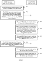
- FIG. 3 is a schematic flowchart of a data transmission method according to an embodiment of the present invention. As shown in FIG. 3 , the method includes the following steps.
- Step 301 An MBMS functional entity in a core network receives a bearer request message.
- Step 302 The MBMS functional entity in the core network determines local MBMS bearer information according to the bearer request message, and sends the determined local MBMS bearer information to a local MBMS functional entity.
- the local MBMS bearer information includes at least identity information of a local MBMS bearer; and the identity information of the local MBMS bearer may be a TMGI and a destination IP address of the local MBMS bearer.
- the local MBMS bearer information may be specifically a context of the local MBMS bearer, for example, may include the identity information of the local MBMS bearer, and may further include QoS, M1 interface identity information, and the like.
- Step 303 The local MBMS functional entity obtains the local MBMS bearer information.
- Step 304 After receiving application layer data sent by a local application server, the local MBMS functional entity determines, based on the obtained local MBMS bearer information, local MBMS bearer information matching the application layer data.
- matching may be performed by using a destination IP address of the application layer data, or matching may be performed by using a tunnel identifier for sending the application layer data. This is not limited.
- the local MBMS functional entity determines local MBMS bearer information matching the application layer data includes: the local MBMS functional entity obtains an IP address of the application layer data, and if the local MBMS bearer information includes the IP address of the application layer data, uses the local MBMS bearer information including the IP address of the application layer data, as the matched local MBMS bearer information.
- Step 305 The local MBMS functional entity sends the application layer data based on the local MBMS bearer information matching the application layer data.
- the local MBMS functional entity first obtains the local MBMS bearer information, and sends the application layer data based on the local MBMS bearer information matching the application layer data.
- the application layer data there is no need to transmit the application layer data to a core network, thereby reducing a delay in transmission of the local application layer data, reducing bandwidth of the core network used by the local application layer data, and increasing a service capacity of a whole network.
- the method further includes the following steps.
- Step 306 The MBMS functional entity in the core network sends deletion request message used for requesting to delete the local MBMS bearer information.
- Step 307 The local MBMS functional entity receives the deletion request message.
- Step 308 The local MBMS functional entity deletes the local MBMS bearer information according to the deletion request message.
- the local MBMS functional entity may also determine whether the local MBMS bearer information needs to be deleted. For example, after the local MBMS functional entity determines that use of the local MBMS bearer is complete, the local MBMS functional entity may actively delete the local MBMS bearer information, and report a result of active deletion to the MBMS functional entity in the core network; or after the local MBMS functional entity determines that use of the local MBMS bearer is complete, the local MBMS functional entity may actively report that use of the local MBMS bearer is complete to the MBMS functional entity in the core network, to trigger the MBMS functional entity in the core network to send a deletion request message.
- local MBMS bearer information that is already created in the local MBMS functional entity may be deleted according to an actual situation and a specific requirement, so as to save storage space in the local MBMS functional entity, effectively reduce a time of matching between the local MBMS bearer information and the application layer data, and improve processing efficiency of the local MBMS functional entity.
- an interface between the local MBMS functional entity and the MBMS functional entity in the core network may be any one of a first interface, a second interface, and a third interface.
- the first interface is an Mx1 interface between the local MBMS functional entity and the MBMS GW in the core network;
- the second interface includes an Mx2 interface between a local MBMS GW_U and an MBMS GW in the core network and an Mz interface between a local BMSC_U and a BMSC in the core network;
- the local MBMS GW_U and the local BMSC_U are obtained by splitting the local MBMS functional entity;
- the third interface is an My interface between the local MBMS functional entity and the BMSC in the core network;
- the BMSC in the core network and the MBMS GW in the core network are obtained by splitting the MBMS functional entity in the core network.
- a function performed by the MBMS functional entity in the core network may be implemented on an entity for performing a 5G control plane function, and a function performed by the local MBMS functional entity may also be implemented on a 5G user plane forwarding entity.
- an interface between a local MBMS functional entity and an MBMS functional entity in a core network is a first interface, a second interface, or a third interface.
- Scenario 1 An interface between a local MBMS functional entity and an MBMS functional entity in a core network is a first interface.
- FIG. 4 illustrates a schematic diagram of a network architecture applicable to the scenario 1.
- the network architecture includes user equipment 401, an evolved UMTS terrestrial radio access network 402, a mobility management entity 403, an MBMS GW 404 in a core network, a BMSC 405 in the core network, a local application server 406, and a local MBMS functional entity 407.
- the MBMS GW 404 in the core network and the BMSC 405 in the core network are obtained by splitting an MBMS functional entity in the core network.
- the local MBMS functional entity only needs to perform a user plane data forwarding function.
- the MBMS functional entity in the core network is mainly responsible for performing signaling interaction between an MME and the local application server to create local MBMS bearer information, and sending the created MBMS bearer information to the local MBMS functional entity, so that the local MBMS functional entity sends, after receiving application layer data sent by the local application server, the application layer data based on the local MBMS bearer information matching the application layer data.
- the local MBMS functional entity includes the following two subfunctions.
- Subfunction 1 That is, functions performed by a local BMSC_U: mainly performing user plane related functions performed by the BMSC, for example, performing some functions related to MBMS data transmission, being responsible for receiving the application layer data, performing some necessary processing (encryption, recoding, and the like) on the application layer data, then forwarding the application layer data to a local MBMS GW_U, and generating a charging record when charging is required; performing a security function; and performing a data content synchronization function.
- a local BMSC_U mainly performing user plane related functions performed by the BMSC, for example, performing some functions related to MBMS data transmission, being responsible for receiving the application layer data, performing some necessary processing (encryption, recoding, and the like) on the application layer data, then forwarding the application layer data to a local MBMS GW_U, and generating a charging record when charging is required; performing a security function; and performing a data content synchronization function.
- functions including data encryption, coding processing, charging record, security, and synchronization functions
- functions other than forwarding the application layer data to the local MBMS GW_U may all be optional functions.
- Subfunction 2 That is, functions performed by the local MBMS GW_U: mainly performing user plane related functions performed by the MBMS GW, for example, distributing the application layer data (sending broadcast data in IP multicast mode) on an M1 interface according to context information determined when a local MBMS bearer is set up.
- the MBMS functional entity in the core network is responsible for performing all MBMS control plane functions, for example, various control functions required in a process of setting up an MBMS bearer, and specifically, all functions implemented in the BMSC other than the local BMSC-U, and all functions implemented in the MBMS GW other than the local MBMS GW_U.
- an interface between the local MBMS functional entity and the MBMS functional entity in the core network is a first interface
- the local MBMS bearer information is determined by the MBMS functional entity in the core network according to a bearer setup request message sent by the local application server.
- the local MBMS bearer information may include parameter information determined when each network element or device (for example, the MBMS GW in the core network and the BMSC in the core network) sets up a local MBMS bearer, for example, identity information of the local MBMS bearer, M1 interface identity information, QoS, and a tunnel identifier for sending the application layer data.
- the local MBMS bearer information may be classified into first MBMS bearer information and second MBMS bearer information.
- the first MBMS bearer information is determined by the BMSC in the core network according to the received bearer setup request message sent by the local application server, and is sent to the MBMS GW in the core network by using a session start request message, for example, identity information of the local MBMS bearer, and QoS.
- the second MBMS bearer information is determined by the MBMS GW in the core network according to the received session start request message sent by the BMSC in the core network, and optionally, is sent to the BMSC in the core network by using a session start response message, for example, the M1 interface identity information.
- FIG. 5A and FIG. 5B are a schematic flowchart of a data transmission method according to an embodiment of the present invention. As shown in FIG. 5A and FIG. 5B , the method includes the following steps.
- Step 501 A local application server sends a bearer setup request message to a BMSC in a core network.
- Step 502 The BMSC in the core network receives the bearer setup request message, determines, according to the bearer setup request message, identity information of a local MBMS functional entity configured to perform user plane data transmission, and allocates, according to a service requirement carried in the bearer setup request message, QoS required by an MBMS bearer and identity information of a local MBMS bearer.
- the bearer setup request message may be specifically received by using an MB2-C interface.
- the bearer setup request message carries identity information of the local application server and/or to-be-broadcast area information; and an alternative step is performed:
- the BMSC in the core network determines, according to the identity information of the local application server and/or the to-be-broadcast area information, identity information of a local MBMS functional entity configured to perform user plane data transmission.
- the alternative step may replace step 502.
- an alternative step may be further performed. This is not limited.
- the identity information of the local application server may be an address of the local application server or other information used to uniquely identify the local application server.
- the identity information of the local MBMS functional entity may be address information of the local MBMS functional entity, or may be any identity that is mapped to an address of a network element and uniquely identifies the network element.
- the to-be-broadcast area information is used to indicate a to-be-broadcast area, and may be specifically physical location information of the to-be-broadcast area, or an identity of a cell, or may be other information that is used to uniquely identify the to-be-broadcast area, for example, information that may assist the BMSC in the core network in determining a location of the to-be-broadcast area.
- the identity information of the local MBMS bearer may include a TMGI and a destination IP address corresponding to the local MBMS bearer.
- the TMGI may be determined in a plurality of manners. For example, after receiving the bearer setup request message, the BMSC in the core network first determines whether the bearer setup request message carries a TMGI; when determining that the bearer setup request message carries a TMGI (the carried TMGI may be a group of available TMGIs obtained by the local application server), obtains the TMGI, and verifies whether the TMGI is legal (for example, whether use of the TMGI is authorized); if the TMGI is legal, the BMSC in the core network uses the TMGI as the identity information of the local MBMS bearer; if the TMGI is illegal, the BMSC in the core network temporarily allocates a group of TMGIs as the identity information of the local MBMS bearer; when determining that the bearer setup request message does not carry the
- the destination IP address corresponding to the local MBMS bearer may also be determined in a plurality of manners. For example, after receiving the bearer setup request message, the BMSC in the core network first determines whether the bearer setup request message carries an IP address, obtains the IP address when determining that the bearer setup request message carries an IP address (the carried IP address may be an available IP address obtained by the local application server from the BMSC in the core network, or an IP address directly allocated by the local application server), verifies whether the IP address is legal (for example, whether the IP address can be used), and if the IP address is legal, uses the IP address as the identity information of the local MBMS bearer; or if the IP address is illegal, the BMSC in the core network temporarily allocates an IP address as the identity information of the local MBMS bearer.
- the carried IP address may be an available IP address obtained by the local application server from the BMSC in the core network, or an IP address directly allocated by the local application server
- verifies whether the IP address is legal for
- the BMSC in the core network When determining that the bearer setup request message does not carry an IP address, the BMSC in the core network temporarily allocates an IP address as the identity information of the local MBMS bearer.
- the destination IP address corresponding to the local MBMS bearer is an IP multicast address.
- Step 503 The BMSC in the core network sends a session start request message to an MBMS GW in the core network.
- the session start request message may include local MBMS bearer information determined in step 502, for example, the identity information of the local MBMS functional entity and the identity information of the local MBMS bearer.
- Step 504 The MBMS GW in the core network allocates, according to the received session start request message, M1 interface identity information required for sending application layer data.
- the M1 interface identity information is a transport layer IP multicast address for distributing M1 interface data.
- step 504 further includes: the MBMS GW in the core network determines, according to the identity information of the local application server and/or to-be-broadcast area information, identity information of a local MBMS functional entity configured to perform user plane data transmission.
- Step 505 The MBMS GW in the core network sends a session start response message to the BMSC in the core network.
- the session start response message may further include the identity information of the local MBMS functional entity.
- Step 506 The BMSC in the core network receives the session start response message.
- Step 507 The BMSC in the core network returns a bearer setup response message to the local application server, where the bearer setup response message may include the destination IP address corresponding to the local MBMS bearer and the identity information of the local MBMS functional entity.
- the bearer setup response message may further include the identity information of the local MBMS bearer.
- step 507 may also occur after step 502.
- the MBMS GW in the core network and the MME, and the MME and an E-UTRAN set up MBMS bearers according to an existing MBMS bearer setup message. Details are not further described herein.
- Step 508 The MBMS GW in the core network sets up a connection to the local MBMS functional entity according to the identity information of the local MBMS functional entity, and sends the local MBMS bearer information to the local MBMS functional entity by using an Mx1 interface between the local MBMS functional entity and the MBMS GW in the core network.
- the local MBMS bearer information may specifically include the destination IP address corresponding to the local MBMS bearer, the identity information of the local MBMS bearer, and the M1 interface identity information, and may further include QoS.
- the identity information of the local MBMS bearer may be specifically a TMGI and the destination IP address corresponding to the local MBMS bearer, or the destination IP address corresponding to the local MBMS bearer, or an ID of the local MBMS bearer. This is not limited.
- first MBMS bearer information may be sent by the BMSC in the core network to the MBMS GW in the core network, and then is sent by the MBMS GW in the core network to the local MBMS functional entity by using the Mx1 interface.
- Step 509 After receiving the bearer setup response message, the application server sends the application layer data to the local MBMS functional entity by using the destination IP address corresponding to the local MBMS bearer and included in the bearer setup response message, that is, sends the application layer data by using the destination IP address corresponding to the local MBMS bearer, as the destination IP address of the application layer data.
- Step 510 After receiving the application layer data sent by the local application server, the local MBMS functional entity determines local MBMS bearer information matching the application layer data.
- the local MBMS functional entity obtains an IP address of the received application layer data, and if the local MBMS bearer information includes the IP address of the application layer data, uses the local MBMS bearer information including the IP address of the application layer data, as the matched local MBMS bearer information.
- Step 511 The local MBMS functional entity sends the application layer data to an E-UTRAN according to the local MBMS bearer information matching the application layer data.
- the local MBMS functional entity sends the application layer data on the M1 interface according to M1 interface identity information in the local MBMS bearer information matching the application layer data.
- M1 interface identity information is the transport layer IP multicast address, obtained in step 504, for distributing the M1 interface data, an IP multicast mode is used for sending, but the E-UTRAN may receive multicast data of the M1 interface in existing mode, and send the data on an air interface to the UE in broadcast mode.
- the foregoing procedure in this embodiment of the present invention may be further applicable to a scenario of modifying a local MBMS bearer.
- the identity information of the local MBMS bearer carried in each message is identity information of the local MBMS bearer that is already set up, and each entity receiving the message updates or replaces the information about the local MBMS bearer that is already set up.
- the destination IP address corresponding to the local MBMS bearer information matching the application layer data is the destination IP address of the application layer data.
- the method further includes: first, the BMSC in the core network and the MBMS GW in the core network, and the MME and the E-UTRAN delete the local MBMS bearer information according to the existing MBMS procedure, and then step 512 is performed.
- Step 512 The MBMS GW in the core network sends a deletion request message for deleting local MBMS bearer information to the local MBMS functional entity, where the deletion request message may include identity information of a to-be-deleted local MBMS bearer, and the identity information of the to-be-deleted local MBMS bearer may be a TMGI.
- Step 513 The local MBMS functional entity deletes, according to the identity information of the to-be-deleted local MBMS bearer, local MBMS bearer information corresponding to the identity information of the local MBMS bearer.
- step 507 may also occur after step 502, and may occur simultaneously with step 503 and step 504.
- the local MBMS functional entity obtains the local MBMS bearer information by using the interface between the local MBMS functional entity and the MBMS functional entity in the core network; and after receiving the application layer data sent by the local application server, the local MBMS functional entity determines the local MBMS bearer information matching the application layer data; and sends the application layer data based on the local MBMS bearer information matching the application layer data.
- the local MBMS functional entity obtains the local MBMS bearer information, and sends the application layer data based on the local MBMS bearer information matching the application layer data.
- the method in the foregoing embodiment is also applicable to a 5G system.
- functions performed by the BMSC and the MBMS GW in the core network, and the MME in the foregoing procedure may be implemented on a unified core network control entity, and do not need to be implemented on an interface between the BMSC and the MBMS GW, and an interface between the MME and the MBMS GW.
- the E-UTRAN may be an 5G access network.
- the function performed by the local MBMS functional entity may also be implemented by using a 5G user plane forwarding entity.
- Scenario 2 An interface between a local MBMS functional entity and an MBMS functional entity in a core network is a second interface.
- FIG. 6 illustrates a schematic diagram of a network architecture applicable to the scenario 2.
- the network architecture includes user equipment 601, an evolved UMTS terrestrial radio access network 602, a mobility management entity 603, an MBMS GW 604 in a core network, a BMSC 605 in the core network, a local application server 606, a local MBMS GW_U 607, and a local BMSC_U 608.
- the MBMS GW 604 in the core network and the BMSC 605 in the core network are obtained by splitting an MBMS functional entity in the core network;
- the local MBMS GW_U 607 and the local BMSC_U 608 are obtained by splitting a local MBMS functional entity;
- the local MBMS GW_U 607 and the local BMSC_U 608 are connected by using an SGi-mb interface.
- an interface between the local MBMS functional entity and the MBMS functional entity in the core network is a second interface
- local MBMS bearer information is determined by the MBMS functional entity in the core network according to a received bearer setup request message sent by the local application server.
- the local MBMS bearer information may include parameter information determined when each network element or device (for example, the MBMS GW in the core network and the BMSC in the core network) sets up a local MBMS bearer. According to different objects for determining the local MBMS bearer information, the local MBMS bearer information may be classified into first MBMS bearer information and second MBMS bearer information.
- the first MBMS bearer information is determined by the BMSC in the core network according to the received bearer setup request message sent by the local application server, and is sent to the MBMS GW in the core network by using a session start request message.
- the identity information of the local MBMS bearer is used to identify a local MBMS bearer, and may be specifically a TMGI and a destination IP address corresponding to the local MBMS bearer.
- the second MBMS bearer information is determined by the MBMS GW in the core network according to the received session start request message sent by the BMSC in the core network, and optionally, is sent to the BMSC in the core network by using a session start response message, for example, M1 interface identity information, used to identify an M1 interface.
- a session start response message for example, M1 interface identity information, used to identify an M1 interface.
- FIG. 7A and FIG. 7B is a schematic flowchart of a data transmission method. As shown in FIG. 7A and FIG. 7B , the method includes the following steps.
- Step 701 A local application server sends a bearer setup request message to a BMSC in a core network.
- Step 702 The BMSC in the core network receives the bearer setup request message, determines, according to the bearer setup request message, identity information of a local BMSC_U configured to perform user plane data transmission, and allocates, according to a service requirement in the bearer setup request message, QoS required by an MBMS bearer, identity information of a local MBMS bearer, and a tunnel identifier for sending application layer data.
- the bearer setup request message may be specifically received by using an MB2-C interface.
- the bearer setup request message carries identity information of the local application server and/or to-be-broadcast area information; and an alternative step is performed:
- the BMSC in the core network determines, according to the identity information of the local application server and/or the to-be-broadcast area information, identity information of a local MBMS functional entity configured to perform user plane data transmission.
- the alternative step may replace step 702.
- an alternative step may be further performed. This is not limited.
- the identity information of the local application server may be an address of the local application server or other information used to uniquely identify the local application server.
- the identity information of the local BMSC_U may be address information of the local BMSC_U, or may be any identity that is mapped to an address of a network element and uniquely identifies the network element.
- the BMSC in the core network may further determine identity information of a local MBMS GW_U.
- the identity information of the local MBMS GW_U may be address information of the local MBMS GW_U, or may be any identity that is mapped to an address of a network element and uniquely identifies the network element.
- the to-be-broadcast area information may be physical location information of a to-be-broadcast area, or an identity of a cell, or may be other information that may assist the BMSC in determining a location of the to-be-broadcast area.
- the identity information of the local MBMS bearer may include a TMGI and a destination IP address corresponding to the local MBMS bearer. Both the TMGI and the destination IP address corresponding to the local MBMS bearer may be determined in a plurality of manners. For details, refer to the descriptions in the embodiment shown in FIG. 5A and FIG. 5B . Details are not further described.
- Step 703 The BMSC in the core network sends a session start request message to an MBMS GW in the core network.
- the session start request message includes local MBMS bearer information determined in step 702, for example, the identity information of the local BMSC_U and the identity information of the local MBMS bearer.
- Step 704 The MBMS GW in the core network allocates, according to the received session start request message, M1 interface identity information required for sending application layer data.
- the M1 interface identity information is a transport layer IP multicast address for distributing M1 interface data.
- the BMSC in the core network may not determine the identity information of the local BMSC_U, but directly sends the identity information of the local application server and/or the to-be-broadcast area information to the MBMS GW in the core network in step 703, so that in step 704, the MBMS GW in the core network determines, according to the identity information of the local application server and/or the to-be-broadcast area information, the identity information of the local BMSC_U configured to perform user plane data transmission.
- the identity information of the local MBMS GW_U may also be determined in a same manner.
- the BMSC in the core network may be responsible for determining the identity information of the local BMSC_U, but the MBMS GW is responsible for determining the identity information of the MBMS GW_U.
- Step 705 The MBMS GW in the core network sends a session start response message to the BMSC in the core network, where if the identity information of the local BMSC_U and/or identity information of a local MBMS GW_U are determined by the MBMS GW in the core network in step 704, the session start response message further includes the identity information of the local BMSC_U and/or the identity information of the local MBMS GW_U.
- Step 706 The BMSC in the core network receives the session start response message.
- Step 707 The BMSC in the core network returns a bearer setup response message to the local application server.
- the bearer setup response message may include the identity information of the local BMSC_U and the identity information of the local MBMS bearer, and optionally, further include the identity information of the local MBMS GW_U.
- step 707 may also occur after step 702.
- the MBMS GW in the core network and the MME, and the MME and an E-UTRAN set up MBMS bearers according to an existing MBMS bearer setup message. Details are not further described herein.
- Step 708 The BMSC in the core network sends, by using an Mz interface between the local BMSC_U and the BMSC in the core network, the local MBMS bearer information created in step 701 to step 707 to the local BMSC_U, where the information may specifically include: QoS, a TMGI, a destination IP address corresponding to the local MBMS bearer, an SGi-mb interface data plane bearer identity, identity information of the local MBMS GW-U, and the like. If a broadcast mode is used, the SGi-mb interface data plane bearer identity is an IP broadcast address of an SGi-mb interface.
- Step 709 The MBMS GW in the core network sends, by using an Mx2 interface between the local MBMS GW_U and the MBMS GW in the core network, context information of an MBMS bearer set up in step 701 to step 707 to the local MBMS GW_U, where the information may specifically include: QoS, a TMGI, a flow entry flow ID, an identity of the SGi-mb interface data plane bearer, M1 interface identity information, identity information of the local BMSC_U, and the like.
- Step 710 After receiving the bearer setup response message, the application server sends the application layer data to the local BMSC_U by using the destination IP address corresponding to the local MBMS bearer and included in the bearer setup response message.
- Step 711 After receiving the application layer data sent by the local application server, the local BMSC_U determines a local MBMS bearer information matching the application layer data. Specifically, the local BMSC_U obtains the IP address of the received application layer data; and if the local MBMS bearer information includes the IP address of the application layer data, the local BMSC_U uses the local MBMS bearer information including the IP address of the application layer data, as the matched local MBMS bearer information.
- Step 712 The local BMSC_U sends, according to the local MBMS bearer information matching the application layer data, the application layer data in a predefined manner by using the SGi-mb interface, where if the broadcast mode is used, the predefined manner is using an IP multicast address of a predefined SGi-mb interface.
- Step 713 The local MBMS GW_U receives the application layer data on the SGi-mb interface in a predefined manner; and if the SGi-mb interface uses the IP broadcast mode for sending, the local MBMS GW_U receives the application layer data according to the IP multicast address of the SGi-mb interface that is obtained in step 709.
- the local MBMS GW_U After receiving the application layer data, the local MBMS GW_U determines the local MBMS bearer information matching the application layer data, and therefore sends the received application layer data on the M1 interface based on the matched local MBMS bearer information. For example, if the M1 interface identity information is the transport layer IP multicast address, obtained in step 704, for distributing the M1 interface data, an IP multicast mode is used for sending, but the E-UTRAN may receive multicast data of the M1 interface in existing mode, and send the multicast data to the UE on an air interface in broadcast mode.
- the local MBMS GW_U may determine, in the following two manners, the local MBMS bearer information matching the application layer data.
- Manner 1 The local MBMS GW_U determines, according to the IP multicast address of the SGi-mb interface for receiving the application layer data, the local MBMS bearer information including the IP multicast address of the SGi-mb interface, as the local MBMS bearer information matching the application layer data.
- Manner 2 The local MBMS GW_U obtains the IP address of the application layer data, and determines the local MBMS bearer information including the IP address of the application layer data, as the local MBMS bearer information matching the application layer data.
- the foregoing procedure in this embodiment of the present invention may be further applicable to a scenario of modifying a local MBMS bearer.
- the identity information of the local MBMS bearer carried in each message is identity information of the local MBMS bearer that is already set up, and each entity receiving the message updates or replaces the information about the local MBMS bearer that is already set up.
- the destination IP address corresponding to the local MBMS bearer information matching the application layer data is the destination IP address of the application layer data.
- the method further includes: first, the BMSC in the core network and the MBMS GW in the core network, and the MME and the E-UTRAN delete the local MBMS bearer information according to the existing MBMS procedure, and then step 714 is performed.
- Step 714 The BMSC in the core network sends a first deletion request message for deleting local MBMS bearer information to the local BMSC_U by using an Mx interface, where the first deletion request message includes identity information of a to-be-deleted local MBMS bearer, and the identity information of the to-be-deleted local MBMS bearer may be a TMGI.
- Step 715 The local BMSC_U deletes the local MBMS bearer information in the local BMSC_U according to the identity information of the to-be-deleted local MBMS bearer.
- Step 716 The MBMS GW in the core network sends a second deletion request message for deleting local MBMS bearer information to the local MBMS GW_U by using the Mz interface, where the second deletion request message includes identity information of a to-be-deleted local MBMS bearer, and the identity information of the to-be-deleted local MBMS bearer may be a TMGI.
- Step 717 The local MBMS GW_U deletes the local MBMS bearer information in the local MBMS GW_U according to the identity information of the to-be-deleted local MBMS bearer.
- step 707 may also occur after step 702, and may occur simultaneously with step 703, step 704, or the like.
- Step 714 and step 716 may also occur simultaneously.
- the local MBMS functional entity obtains the local MBMS bearer information by using the interface between the local MBMS functional entity and the MBMS functional entity in the core network; and after receiving the application layer data sent by the local application server, the local MBMS functional entity determines the local MBMS bearer information matching the application layer data; and sends the application layer data based on the local MBMS bearer information matching the application layer data.
- the local MBMS functional entity obtains the local MBMS bearer information, and sends the application layer data based on the local MBMS bearer information matching the application layer data.
- Scenario 3 An interface between a local MBMS functional entity and an MBMS functional entity in a core network is a third interface.
- FIG. 8 illustrates a schematic diagram of a network architecture applicable to the scenario 3.
- the network architecture includes user equipment 801, an evolved UMTS terrestrial radio access network 802, a mobility management entity 803, an MBMS GW 804 in a core network, a BMSC 805 in the core network, a local application server 806, and a local MBMS functional entity 807.
- the MBMS GW 804 in the core network and the BMSC 805 in the core network are obtained by splitting an MBMS functional entity in the core network.
- the MBMS functional entity in the core network is responsible for managing identity information of all MBMS bearers. Specifically, the BMSC in the core network uniformly manages MBMS bearer resources, and allocates identity information of different local MBMS bearers to a same broadcast area, to ensure that a phenomenon of identity collision does not occur in the same broadcast area.
- An interface between the local MBMS functional entity and the MBMS functional entity in the core network is a third interface, and local MBMS bearer information is obtained by the local MBMS functional entity according to a received bearer setup request message sent by the local application server.
- the local MBMS bearer information may include parameter information determined when each network element or device (for example, the local MBMS functional entity and the BMSC in the core network) sets up a local MBMS bearer. According to different objects for determining the local MBMS bearer information, the local MBMS bearer information may be classified into third MBMS bearer information and fourth MBMS bearer information.
- the third MBMS bearer information is determined by the BMSC in the core network according to a received bearer identity request message sent by the local MBMS functional entity, and is sent to the local MBMS functional entity by using a bearer identity response message, for example, identity information of the local MBMS bearer.
- the bearer identity request message is sent when the local MBMS functional entity determines, after receiving the bearer setup request message sent by the local application server, that the identity information of the local MBMS bearer does not exist in the local MBMS functional entity.
- the fourth MBMS bearer information is determined by the local MBMS functional entity according to the received bearer setup request message sent by the local application server, for example, a QoS parameter, and M1 interface identity information.
- FIG. 9A and FIG. 9B are a schematic flowchart of still another data transmission method according to an embodiment of the present invention. As shown in FIG. 9A and FIG. 9B , the method includes the following steps.
- Step 901 A local application server sends a bearer setup request message to a local MBMS functional entity, where the bearer setup request message may include to-be-broadcast area information.
- the to-be-broadcast area information is used to indicate a to-be-broadcast area, and may be specifically physical location information of the to-be-broadcast area, or an identity of a cell, or may be other information that may assist a BMSC in determining a location of the to-be-broadcast area.
- Step 902 The local MBMS functional entity receives the bearer setup request message by using an MB2-U interface, and may directly perform step 903, or may first determine whether available identity information exists in the local MBMS functional entity, and if available identity information exists, determine the available identity information as identity information of a local MBMS bearer, and perform step 904, or if available identity information does not exist, perform step 903. Further, when determining whether available identity information exists, the local MBMS functional entity may determine, according to the to-be-broadcast area information carried in the bearer setup request message, whether matched identity information exists.
- Step 903 The local MBMS functional entity sends a bearer identity request message to a BMSC in a core network by using an MBy interface, where the bearer identity request message may include the to-be-broadcast area information.
- Step 904 After receiving the bearer identity request message, the BMSC in the core network may allocate a piece of available identity information (which may include a TMGI and a destination IP address corresponding to the local MBMS bearer) to the local MBMS bearer according to a requirement, and send the identity information to the local MBMS functional entity by using a bearer identity response message.
- a piece of available identity information which may include a TMGI and a destination IP address corresponding to the local MBMS bearer
- the BMSC in the core network may select, according to the to-be-broadcast area information carried in the bearer identity request message and a correspondence between the allocated identity information of the local MBMS bearer and the to-be-broadcast area information, identity information that is not allocated in a related broadcast area.
- the BMSC in the core network may store a correspondence between the allocated identity information of the local MBMS bearer and broadcast area information, where the identity information of the local MBMS bearer may be a TMGI.
- the correspondence between the allocated identity information of the local MBMS bearer and the broadcast area information may be stored in a form of a data table, as shown in Table 1.
- Table 1 Correspondence between an allocated TMGI and broadcast area information Broadcast area information Allocated TMGI Broadcast area 1 ******X ******y ... Broadcast area 2 ******p ******q ... ... ... ... ...
- the BMSC in the core network allocates an available TMGI to a current local MBMS bearer after obtaining a TMGI that is already allocated to the broadcast area 1 from a table (that is, Table 1) of a correspondence between an allocated TMGI and broadcast area information, where the TMGI is different from the TMGI (such as ******x, or ******y) that is already allocated to the broadcast area 1.
- the BMSC in the core network may update Table 1 according to a status of a local MBMS bearer created by the local MBMS functional entity, for example, update content in Table 1 when the BMSC in the core network receives a message reported by the local MBMS functional entity and indicating that identity information of the local MBMS bearer and corresponding broadcast area information are already created successfully.
- Step 905 The local MBMS functional entity allocates QoS, M1 interface identity information, and the like after obtaining the identity information of the local MBMS bearer, and if an M1 interface uses an IP broadcast mode for sending, the M1 interface identity information is a transport layer IP multicast address for distributing M1 interface data.
- the local MBMS functional entity, the MME, and an E-UTRAN set up MBMS bearers according to an existing MBMS bearer setup message. Details are not further described herein.
- Step 906 The local MBMS functional entity sends a bearer setup response message to the local application server, where the bearer setup response message includes obtained local MBMS bearer information, and may specifically include the identity information of the local MBMS bearer, a QoS parameter, and the like.
- Step 907 the local MBMS functional entity reports a creation result of the local MBMS bearer to the BMSC in the core network; if the foregoing procedure is performed successfully, the local MBMS bearer is created successfully, and a message reported by the local MBMS functional entity to the BMSC in the core network and indicating the creation result of the local MBMS bearer includes the identity information of the local MBMS bearer and corresponding to-be-broadcast area information, so that the BMSC in the core network updates the content in Table 1 according to the received creation message; or if the local MBMS bearer fails to be created, the BMSC in the core network may not update the content in Table 1.
- the local MBMS functional entity may actively report the creation result of the local MBMS bearer to the BMSC in the core network after determining the creation result of the local MBMS bearer; or the local MBMS functional entity may report the creation result of the local MBMS bearer to the BMSC in the core network after receiving a query request message sent by the BMSC in the core network.
- the BMSC in the core network may periodically send a query request message, where the query request message includes identity information of the local MBMS bearer that is just allocated.
- the local MBMS functional entity After receiving the query request message, the local MBMS functional entity obtains the creation result of the local MBMS bearer according to the identity information of the local MBMS bearer in the query request message, and sends the creation result to the BMSC in the core network by using a query response message.
- the BMSC in the core network stops sending the query request message, and performs a corresponding operation according to the query response message, for example, updates Table 1.
- step 907 is optional, and the BMSC in the core network may also actively update Table 1 according to a specified period. This is not specifically limited in this embodiment of the present invention.
- Step 908 After receiving the bearer setup response message, the application server sends application layer data to the local MBMS functional entity by using the destination IP address corresponding to the local MBMS bearer and included in the bearer setup response message.
- Step 909 After receiving the application layer data sent by the local application server, the local MBMS functional entity determines local MBMS bearer information matching the application layer data. Specifically, the local MBMS functional entity obtains an IP address of the received application layer data; and if the local MBMS bearer information includes the IP address of the application layer data, the local MBMS functional entity uses the local MBMS bearer information including the IP address of the application layer data, as the matched local MBMS bearer information.
- Step 910 The local MBMS functional entity sends the application layer data to an E-UTRAN according to the local MBMS bearer information matching the application layer data. Specifically, the local MBMS functional entity sends the application layer data on the M1 interface according to M1 interface identity information in the local MBMS bearer information matching the application layer data. For example, if the M1 interface identity information is the transport layer IP multicast address, obtained in step 904, for distributing the M1 interface data, an IP multicast mode is used for sending, but the E-UTRAN may receive multicast data of the M1 interface in existing mode, and send the data on the air interface to the UE in broadcast mode.
- M1 interface identity information is the transport layer IP multicast address, obtained in step 904
- an IP multicast mode is used for sending, but the E-UTRAN may receive multicast data of the M1 interface in existing mode, and send the data on the air interface to the UE in broadcast mode.
- the foregoing procedure in this embodiment of the present invention may be further applicable to a scenario of modifying a local MBMS bearer.
- the identity information of the local MBMS bearer carried in each message is identity information of the local MBMS bearer that is already set up, and each entity receiving the message updates or replaces the information about the local MBMS bearer that is already set up.
- the destination IP address corresponding to the local MBMS bearer information matching the application layer data is the destination IP address of the application layer data.
- the method further includes the following steps.
- Step 911 Optionally, if the MBMS functional entity in the core network determines that the identity information of the local MBMS bearer needs to be deleted, the BMSC in the core network sends a deletion request message to the local MBMS functional entity, where the deletion request message includes identity information of a to-be-deleted local MBMS bearer, and the identity information of the to-be-deleted local MBMS bearer may be a TMGI.
- Step 912 The local MBMS functional entity deletes, according to the identity information of the to-be-deleted local MBMS bearer, local MBMS bearer information corresponding to the identity information of the local MBMS bearer.
- the local MBMS functional entity may report a deletion result to the BMSC in the core network after deleting the local MBMS bearer information, so that the BMSC in the core network updates the content in Table 1 according to the deletion result. For example, if the identity information of the to-be-deleted local MBMS bearer is a TMGI in the broadcast area 1, the BMSC in the core network may delete, after receiving a deletion success result sent by the local MBMS functional entity, the TMGI from the allocated TMGI corresponding to the broadcast area 1.
- the foregoing step of deleting the local MBMS bearer information may also be initiated by the local MBMS functional entity.
- the local MBMS functional entity may directly report the deletion result to the BMSC in the core network after deleting the local MBMS bearer information, so that the BMSC in the core network updates the content in Table 1 according to the deletion result.
- the local MBMS functional entity obtains the local MBMS bearer information by using the interface between the local MBMS functional entity and the MBMS functional entity in the core network; and after receiving the application layer data sent by the local application server, the local MBMS functional entity determines the local MBMS bearer information matching the application layer data; and sends the application layer data based on the local MBMS bearer information matching the application layer data.
- the local MBMS functional entity obtains the local MBMS bearer information, and sends the application layer data based on the local MBMS bearer information matching the application layer data.
- the method in the foregoing embodiment is also applicable to a 5G system.
- functions performed by the MBMS functional entity in the core network and the MME in the foregoing procedure may be implemented on a unified core network control entity.
- the E-UTRAN may be an access network device for 5G access.
- an embodiment of the present invention further provides a local MBMS functional entity and a core MBMS network element.
- a local MBMS functional entity and a core MBMS network element For specific content about the local MBMS functional entity and the core MBMS network element, refer to the foregoing implementation method.
- FIG. 10 is a schematic structural diagram of a local MBMS functional entity according to an embodiment of the present invention.
- the local MBMS functional entity is configured to perform the foregoing method procedure, and as shown in FIG. 10 , includes:
- the receiving module 1001 is further configured to obtain a destination IP address of the application layer data; and the processing module 1002 is specifically configured to use the local MBMS bearer information including the destination IP address of the application layer data, as the matched local MBMS bearer information if the local MBMS bearer information includes the destination IP address of the application layer data.
- an MBMS functional entity in a core network includes a broadcast/multicast service center BMSC in the core network and a multimedia broadcast/multicast service gateway MBMS GW in the core network; and the receiving module 1001 is specifically configured to: receive, by using an Mx1 interface between the local MBMS functional entity and the MBMS GW in the core network, the local MBMS bearer information sent by the MBMS GW in the core network.
- an MBMS functional entity in a core network includes a BMSC in the core network and an MBMS GW in the core network;
- the local MBMS functional entity includes a local broadcast/multicast service center user plane BMSC_U and a local multimedia broadcast/multicast service gateway user plane MBMS GW_U;
- the local MBMS bearer information includes first MBMS bearer information and second MBMS bearer information;
- the receiving module 1001 includes a receiving module in the local BMSC_U and a receiving module in the local MBMS GW_U, where the receiving module in the local BMSC_U is specifically configured to receive the first MBMS bearer information by using an Mz interface between the local BMSC_U and the BMSC in the core network; and the receiving module in the local MBMS GW_U is specifically configured to receive the first MBMS bearer information and the second MBMS bearer information by using an Mx2 interface between the local MBMS GW_U and the MBMS GW in the
- an MBMS functional entity in a core network includes a BMSC in the core network and an MBMS GW in the core network; and the local MBMS bearer information includes third MBMS bearer information and fourth MBMS bearer information;
- the receiving module 1001 is further configured to receive a bearer setup request message sent by the local application server;
- the sending module 1003 is further configured to send a bearer identity request message to the BMSC in the core network after the receiving module receives the bearer setup request message;
- the receiving module 1001 is specifically configured to: after the sending module sends the bearer identity request message, receive, by using an My interface between the local MBMS functional entity and the BMSC in the core network, the third MBMS bearer information sent by the BMSC in the core network;
- the processing module 1002 is further configured to determine the fourth MBMS bearer information according to the bearer setup request message.
- the local MBMS bearer information includes a destination IP address corresponding to a local MBMS bearer; and the sending module 1003 is further configured to: send the destination IP address corresponding to the local MBMS bearer to the local application server by using a bearer setup response message.
- the local MBMS functional entity further includes a deletion module 1004, configured to delete the matched local MBMS bearer information.
- the receiving module 1001 is further configured to:
- the deletion request message includes a first deletion request message and a second deletion request message
- the deletion module includes a deletion module in the local BMSC_U and a deletion module in the local MBMS GW_U, where the deletion module in the local BMSC_U is specifically configured to delete local MBMS bearer information in the local BMSC_U according to the first deletion request message; and the deletion module in the local MBMS GW_U is specifically configured to delete local MBMS bearer information in the local MBMS GW_U according to the second deletion request message.
- the local MBMS functional entity obtains the local MBMS bearer information by using the interface between the local MBMS functional entity and the MBMS functional entity in the core network; and after receiving the application layer data sent by a local application server, the local MBMS functional entity determines the local MBMS bearer information matching the application layer data; and sends the application layer data based on the local MBMS bearer information matching the application layer data.
- the local MBMS functional entity first obtains the local MBMS bearer information, and sends the application layer data based on the local MBMS bearer information matching the application layer data.
- FIG. 11 is a schematic structural diagram of an MBMS functional entity in a core network according to an embodiment of the present invention.
- the MBMS functional entity in the core network is configured to perform the foregoing method procedure.
- An embodiment of the present invention provides a multimedia broadcast/multicast service MBMS functional entity in a core network, where the MBMS functional entity in the core network includes:
- the bearer request message is a bearer setup request message sent by a local application server; and the sending module 1103 is further configured to: send a bearer setup response message to the local application server.
- the local MBMS bearer information includes a destination IP address corresponding to a local MBMS bearer
- the bearer setup response message includes the destination IP address corresponding to the local MBMS bearer
- the bearer setup request message includes identity information of the local application server and/or to-be-broadcast area information; and the processing module 1102 is further configured to:
- the MBMS functional entity in the core network includes a broadcast/multicast service center BMSC in the core network and a multimedia broadcast/multicast service gateway MBMS GW in the core network; and the processing module 1102 includes a processing module in the BMSC in the core network and a processing module in the MBMS GW in the core network, where the processing module in the BMSC in the core network is configured to determine the identity information of the local BMSC_U and the identity information of the local MBMS GW_U according to the identity information of the local application server and/or the to-be-broadcast area information; or the processing module in the BMSC in the core network is configured to determine the identity information of the local BMSC_U according to the identity information of the local application server and/or the to-be-broadcast area information, and the processing module in the MBMS GW in the core network is configured to determine the identity information of the local MBMS GW_U according to the identity information of the local application server and/or the to-be-broadcast
- the MBMS functional entity in the core network includes the BMSC in the core network and the MBMS GW in the core network;
- the local MBMS bearer information includes first MBMS bearer information and second MBMS bearer information;
- the processing module 1102 includes the processing module in the BMSC in the core network and the processing module in the MBMS GW in the core network;
- the sending module 1103 includes a sending module in the BMSC in the core network and a sending module in the MBMS GW in the core network, where the processing module in the BMSC in the core network determines the first MBMS bearer information according to the bearer setup request message sent by the local application server;
- the sending module in the BMSC in the core network is further configured to send a session start request message to the MBMS GW in the core network, where the session start request message includes the first MBMS bearer information; and the processing module in the MBMS GW in the core network determines the second MBMS bearer information according to the session start request
- the first MBMS bearer information further includes the destination IP address corresponding to the local MBMS bearer.
- the session start request message further includes the identity information of the local MBMS GW_U determined by the BMSC in the core network or the identity information of the local MBMS functional entity.
- the sending module in the MBMS GW in the core network is specifically configured to send the determined first MBMS bearer information and second MBMS bearer information to the local MBMS functional entity by using an Mx1 interface between the BMSC in the core network and the local MBMS functional entity.
- the local MBMS functional entity includes the local MBMS GW_U and the local BMSC_U; the sending module in the BMSC in the core network sends the first MBMS bearer information to the local BMSC_U by using an Mz interface between the local BMSC_U and the BMSC in the core network; and the sending module in the MBMS GW in the core network sends the first MBMS bearer information and the second MBMS bearer information to the local MBMS GW_U by using an Mx2 interface between the local MBMS GW_U and the MBMS GW in the core network.
- the local MBMS bearer information includes identity information of a local MBMS bearer; and the bearer request message is a bearer identity request message sent by the local MBMS functional entity; the processing module 1102 is specifically configured to determine the identity information of the local MBMS bearer according to the bearer identity request message sent by the local MBMS functional entity; and the sending module 1103 is specifically configured to send the identity information of the local MBMS bearer to the local MBMS functional entity.
- the bearer identity request message includes to-be-broadcast area information; and the processing module 1102 is specifically configured to: determine the identity information of the local MBMS bearer according to the to-be-broadcast area information.
- the MBMS functional entity in the core network includes a BMSC in the core network and an MBMS GW in the core network; and the sending module 1103 includes a sending module in the BMSC in the core network and a sending module in the MBMS GW in the core network, where the sending module in the BMSC in the core network sends the identity information of the local MBMS bearer to the local MBMS functional entity by using an My interface between the local MBMS functional entity and the BMSC in the core network.
- the MBMS functional entity in the core network further includes a deletion module 1104, configured to determine to delete the local MBMS bearer information; and the sending module 1103 is further configured to send, to the local MBMS functional entity, deletion request message for deleting the local MBMS bearer information.
- the local MBMS functional entity includes the local MBMS GW_U and the local BMSC_U
- the MBMS functional entity in the core network includes the BMSC in the core network and the MBMS GW in the core network
- the deletion request message includes a first deletion request message and a second deletion request message
- the sending module 1103 includes the sending module in the BMSC in the core network and the sending module in the MBMS GW in the core network, where the sending module in the BMSC in the core network sends the first deletion request message to the local BMSC_U by using the Mz interface between the local BMSC_U and the BMSC in the core network; and the sending module in the MBMS GW in the core network sends the second deletion request message to the local MBMS GW_U by using the Mx2 interface between the local MBMS GW_U and the MBMS GW in the core network.
- the local MBMS functional entity obtains the local MBMS bearer information by using the interface between the local MBMS functional entity and the MBMS functional entity in the core network; and after receiving the application layer data sent by the local application server, the local MBMS functional entity determines the local MBMS bearer information matching the application layer data; and sends the application layer data based on the local MBMS bearer information matching the application layer data.
- the local MBMS functional entity first obtains the local MBMS bearer information, and sends the application layer data based on the local MBMS bearer information matching the application layer data.
- FIG. 12 is a schematic structural diagram of another local MBMS functional entity according to an embodiment of the present invention.
- the local MBMS functional entity includes a processor 1201 and a memory 1202.
- the processor 1201 is configured to: obtain local MBMS bearer information; receive application layer data sent by a local application server; determine, based on the obtained local MBMS bearer information, local MBMS bearer information matching the application layer data; and send the application layer data based on the matched local MBMS bearer information.
- the memory 1202 may store data used when the processor performs an operation.
- the memory 1202 may include a volatile memory (volatile memory), for example, a random access memory (random-access memory, RAM).
- the memory 1202 may also include a non-volatile memory (non-volatile memory), for example, a read-only memory (read-only memory, ROM), a flash memory (flash memory), a hard disk drive (hard disk drive, HDD), or a solid-state drive (solid-state drive, SSD).
- the memory 1202 may further include a combination of the foregoing types of memories.
- the processor 1201 is further configured to: obtain a destination IP address of the application layer data; and use the local MBMS bearer information including the destination IP address of the application layer data, as the matched local MBMS bearer information if the local MBMS bearer information includes the destination IP address of the application layer data.
- an MBMS functional entity in a core network includes a broadcast/multicast service center BMSC in the core network and a multimedia broadcast/multicast service gateway MBMS GW in the core network; and the processor 1201 is specifically configured to receive, by using an Mx1 interface between the local MBMS functional entity and the MBMS GW in the core network, the local MBMS bearer information sent by the MBMS GW in the core network.
- an MBMS functional entity in a core network includes a BMSC in the core network and an MBMS GW in the core network;
- the local MBMS functional entity includes a local broadcast/multicast service center user plane BMSC_U and a local multimedia broadcast/multicast service gateway user plane MBMS GW_U;
- the local MBMS bearer information includes first MBMS bearer information and second MBMS bearer information;
- the processor includes a processor in the local BMSC_U and a processor in the local MBMS GW_U, where the processor in the local BMSC_U is specifically configured to receive the first MBMS bearer information by using an Mz interface between the local BMSC_U and the BMSC in the core network; and the processor in the local MBMS GW_U is specifically configured to receive the first MBMS bearer information and the second MBMS bearer information by using an Mx2 interface between the local MBMS GW_U and the MBMS GW in the core network.
- an MBMS functional entity in a core network includes a BMSC in the core network and an MBMS GW in the core network; and the local MBMS bearer information includes third MBMS bearer information and fourth MBMS bearer information;
- the processor 1201 is configured to: receive a bearer setup request message sent by the local application server; send a bearer identity request message to the BMSC in the core network; and receive, by using an My interface between the local MBMS functional entity and the BMSC in the core network, the third MBMS bearer information sent by the BMSC in the core network; and the processor is further configured to determine the fourth MBMS bearer information according to the bearer setup request message.
- the local MBMS bearer information includes a destination IP address corresponding to a local MBMS bearer; and the processor 1201 is further configured to send the destination IP address corresponding to the local MBMS bearer to the local application server by using a bearer setup response message.
- the processor 1201 is further configured to delete the matched local MBMS bearer information.
- the processor 1201 is specifically configured to: receive deletion request message sent by the MBMS functional entity in the core network and used for requesting to delete the matched local MBMS bearer information; and delete the matched local MBMS bearer information according to the deletion request message.
- the deletion request message includes a first deletion request message and a second deletion request message
- the processor includes a processor in the local BMSC_U and a processor in the local MBMS GW_U, where the processor in the local BMSC_U is specifically configured to delete local MBMS bearer information in the local BMSC_U according to the first deletion request message; and the processor in the local MBMS GW_U is specifically configured to delete local MBMS bearer information in the local MBMS GW_U according to the second deletion request message.
- a bus architecture may include any quantity of interconnect buses and bridges, specifically for interconnecting various circuits of one or more processors and a memory.
- the bus architecture may further interconnect various other circuits such as a peripheral device, a voltage regulator, and a power management circuit. These are all well known in the art, and therefore are not further described in the specification.
- a bus interface provides an interface.
- the processor is responsible for managing the bus architecture and general processing.
- FIG. 13 is a schematic structural diagram of another MBMS functional entity in a core network according to an embodiment of the present invention.
- the MBMS functional entity in the core network is configured to perform the foregoing method procedure, and includes a processor 1301 and a memory 1302.
- the processor 1301 is configured to: receive a bearer request message; determine local MBMS bearer information according to the bearer request message; and send the determined local MBMS bearer information to a local MBMS functional entity.
- the memory 1302 may store data used when the processor performs an operation.
- the memory 1302 may include a volatile memory (volatile memory), for example, a random access memory (random-access memory, RAM).
- the memory 1302 may also include a non-volatile memory (non-volatile memory), for example, a read-only memory (read-only memory, ROM), a flash memory (flash memory), a hard disk drive (English: hard disk drive, HDD), or a solid-state drive (solid-state drive, SSD).
- the memory 1302 may further include a combination of the foregoing types of memories.
- the bearer request message is a bearer setup request message sent by a local application server; and the processor 1301 is further configured to send a bearer setup response message to the local application server.
- the local MBMS bearer information includes a destination IP address corresponding to a local MBMS bearer
- the bearer setup response message includes the destination IP address corresponding to the local MBMS bearer
- the bearer setup request message includes identity information of the local application server and/or to-be-broadcast area information; and the processor 1301 is further configured to:
- the MBMS functional entity in the core network includes a broadcast/multicast service center BMSC in the core network and a multimedia broadcast/multicast service gateway MBMS GW in the core network; and the processor 1301 includes a processor in the BMSC in the core network and a processor in the MBMS GW in the core network, where the processor in the BMSC in the core network is configured to determine the identity information of the local BMSC_U and the identity information of the local MBMS GW_U according to the identity information of the local application server and/or the to-be-broadcast area information; or the processor in the BMSC in the core network is configured to determine the identity information of the local BMSC_U according to the identity information of the local application server and/or the to-be-broadcast area information, and the processor in the MBMS GW in the core network is configured to determine the identity information of the local MBMS GW_U according to the identity information of the local application server and/or the to-be-broadcast area information; or
- the MBMS functional entity in the core network includes the BMSC in the core network and the MBMS GW in the core network;
- the local MBMS bearer information includes first MBMS bearer information and second MBMS bearer information;
- the processor 1301 includes the processor in the BMSC in the core network and the processor in the MBMS GW in the core network, where the processor in the BMSC in the core network determines the first MBMS bearer information according to the bearer setup request message sent by the local application server, and sends a session start request message to the MBMS GW in the core network, where the session start request message includes the first MBMS bearer information; and the processor in the MBMS GW in the core network determines the second MBMS bearer information according to the session start request message.
- the first MBMS bearer information further includes the destination IP address corresponding to the local MBMS bearer.
- the session start request message further includes the identity information of the local MBMS GW_U determined by the BMSC in the core network or the identity information of the local MBMS functional entity.
- the processor in the MBMS GW in the core network is specifically configured to send the determined first MBMS bearer information and second MBMS bearer information to the local MBMS functional entity by using an Mx1 interface between the BMSC in the core network and the local MBMS functional entity.
- the local MBMS functional entity includes the local MBMS GW_U and the local BMSC_U; the processor in the BMSC in the core network sends the first MBMS bearer information to the local BMSC_U by using an Mz interface between the local BMSC_U and the BMSC in the core network; and the processor in the MBMS GW in the core network sends the first MBMS bearer information and the second MBMS bearer information to the local MBMS GW_U by using an Mx2 interface between the local MBMS GW_U and the MBMS GW in the core network.
- the local MBMS bearer information includes identity information of a local MBMS bearer; and the bearer request message is a bearer identity request message sent by the local MBMS functional entity; and the processor 1301 is specifically configured to determine the identity information of the local MBMS bearer according to the bearer identity request message sent by the local MBMS functional entity; and send the identity information of the local MBMS bearer to the local MBMS functional entity.
- the bearer identity request message includes to-be-broadcast area information; and the processor 1301 is specifically configured to: determine the identity information of the local MBMS bearer according to the to-be-broadcast area information.
- the MBMS functional entity in the core network includes a BMSC in the core network and an MBMS GW in the core network; and the processor includes a processor in the BMSC in the core network and a processor in the MBMS GW in the core network, where the processor in the BMSC in the core network sends the identity information of the local MBMS bearer to the local MBMS functional entity by using an My interface between the local MBMS functional entity and the BMSC in the core network.
- the processor 1301 is further configured to determine to delete the local MBMS bearer information, and send, to the local MBMS functional entity, deletion request message for deleting the local MBMS bearer information.
- the local MBMS functional entity includes the local MBMS GW_U and the local BMSC_U
- the MBMS functional entity in the core network includes the BMSC in the core network and the MBMS GW in the core network
- the deletion request message includes a first deletion request message and a second deletion request message
- the processor 1301 includes the processor in the BMSC in the core network and the processor in the MBMS GW in the core network, where the processor in the BMSC in the core network sends the first deletion request message to the local BMSC_U by using the Mz interface between the local BMSC_U and the BMSC in the core network; and the processor in the MBMS GW in the core network sends the second deletion request message to the local MBMS GW_U by using the Mx2 interface between the local MBMS GW_U and the MBMS GW in the core network.
- a bus architecture may include any quantity of interconnect buses and bridges, specifically for interconnecting various circuits of one or more processors represented by the processor and a memory represented by the memory.
- the bus architecture may further interconnect various other circuits such as a peripheral device, a voltage regulator, and a power management circuit. These are all well known in the art, and therefore are not further described in the specification.
- a bus interface provides an interface.
- the processor is responsible for managing the bus architecture and general processing.
- the local MBMS functional entity obtains the local MBMS bearer information by using the interface between the local MBMS functional entity and the MBMS functional entity in the core network; and after receiving the application layer data sent by the local application server, the local MBMS functional entity determines the local MBMS bearer information matching the application layer data; and sends the application layer data based on the local MBMS bearer information matching the application layer data.
- the local MBMS functional entity first obtains the local MBMS bearer information, and sends the application layer data based on the local MBMS bearer information matching the application layer data.
- the embodiments of the present invention may be provided as a method, or a computer program product. Therefore, the present invention may use a form of hardware only embodiments, software only embodiments, or embodiments with a combination of software and hardware. Moreover, the present invention may use a form of a computer program product that is implemented on one or more computer-usable storage media (including but not limited to a disk memory, a CD-ROM, an optical memory, and the like) that include computer-usable program code.
- computer-usable storage media including but not limited to a disk memory, a CD-ROM, an optical memory, and the like
- These computer program instructions may be provided for a general-purpose computer, a dedicated computer, an embedded processor, or a processor of any other programmable data processing device to generate a machine, so that the instructions executed by a computer or a processor of any other programmable data processing device generate an apparatus for implementing a specific function in one or more processes in the flowcharts and/or in one or more blocks in the block diagrams.
- These computer program instructions may be stored in a computer readable memory that can instruct the computer or any other programmable data processing device to work in a specific manner, so that the instructions stored in the computer readable memory generate an artifact that includes an instruction apparatus.
- the instruction apparatus implements a specific function in one or more processes in the flowcharts and/or in one or more blocks in the block diagrams.
- These computer program instructions may be loaded onto a computer or another programmable data processing device, so that a series of operations and steps are performed on the computer or the another programmable device, thereby generating computer-implemented processing. Therefore, the instructions executed on the computer or the another programmable device provide steps for implementing a specific function in one or more processes in the flowcharts and/or in one or more blocks in the block diagrams.
Landscapes
- Engineering & Computer Science (AREA)
- Computer Networks & Wireless Communication (AREA)
- Signal Processing (AREA)
- Multimedia (AREA)
- Databases & Information Systems (AREA)
- Mobile Radio Communication Systems (AREA)
Claims (14)
- Architecture de réseau sans fil prenant en charge un service de radiodiffusion/multidiffusion multimédia, MBMS, comportant sur un côté réseau d'infrastructure un réseau d'accès radio terrestre (102, 202, 402) connecté à une entité fonctionnelle (204) de service de radiodiffusion/multidiffusion multimédia, MBMS, comprenant un centre de service de radiodiffusion/multidiffusion/multimédia (105, 405), BMSC, et une passerelle de service de radiodiffusion/multidiffusion multimédia (104, 404), MBMS GW, et sur un côté local un serveur d'application local (205, 406) connecté à une entité fonctionnelle de service de radiodiffusion/multidiffusion multimédia, MBMS, locale (206, 407), l'entité fonctionnelle MBMS locale (407) étant connectée par le biais d'une interface Mx1 au BMSC (405) sur le côté réseau, l'architecture de réseau sans fil comportant l'entité fonctionnelle MBMS, l'entité fonctionnelle MBMS locale et le serveur d'application local, et l'entité fonctionnelle MBMS locale comprenant :a) un module de réception (1001), conçu pour obtenir une information de porteuse MBMS locale, et recevoir des données de couche d'application en provenance du serveur d'application local ;b) un module de traitement (1002), conçu pour déterminer, d'après l'information de porteuse MBMS locale obtenue, une information de porteuse MBMS locale concordant avec les données de couche d'application ; etc) un module d'envoi (1003), conçu pour envoyer les données de couche d'application d'après l'information de porteuse MBMS locale concordante ; etd1) dans laquelle l'entité fonctionnelle MBMS locale comprend un plan utilisateur de centre de service de radiodiffusion/multidiffusion, BMSC_U, local et un plan utilisateur de passerelle de service de radiodiffusion/multidiffusion multimédia, MBMS GW_U, local ; l'information de porteuse MBMS locale comprend une première information de porteuse MBMS et une deuxième information de porteuse MBMS ; et le module de réception (1001) comprend un module de réception dans le BMSC_U local et un module de réception dans le MBMS GW_U local, dans laquelled2) le module de réception dans le BMSC_U local est conçu pour recevoir la première information de porteuse MBMS en utilisant une interface Mz entre le BMSC_U local et le BMSC dans le réseau d'infrastructure ; etd3) le module de réception dans le MBMS GW_U local est conçu pour recevoir la première information de porteuse MBMS et la deuxième information de porteuse MBMS en utilisant une interface Mx2 entre le MBMS GW_U local et la MBMS GW dans le réseau d'infrastructure.
- Architecture comportant l'entité fonctionnelle MBMS locale selon la revendication 1, dans laquelle le module de réception (1001) est en outre conçu pour obtenir une adresse IP de destination des données de couche d'application ; et
le module de traitement (1002) est en outre conçu pour utiliser l'information de porteuse MBMS locale comprenant l'adresse IP de destination des données de couche d'application, en tant qu'information de porteuse MBMS locale concordante si l'information de porteuse MBMS locale comprend l'adresse IP de destination des données de couche d'application. - Architecture comportant l'entité fonctionnelle MBMS locale selon la revendication 1 ou 2, dans laquelle le module de réception (1001) est en outre conçu pour :
recevoir, en utilisant l'interface Mx1 entre l'entité fonctionnelle MBMS locale et une passerelle de service de radiodiffusion/multidiffusion multimédia, MBMS GW, dans le réseau d'infrastructure, l'information de porteuse MBMS locale en provenance de la MBMS GW dans le réseau d'infrastructure. - Architecture comportant l'entité fonctionnelle MBMS locale selon la revendication 1, dans laquelle l'information de porteuse MBMS locale comprend une troisième information de porteuse MBMS et une quatrième information de porteuse MBMS ; le module de réception (1001) est en outre conçu pour recevoir un message de demande d'établissement de porteuse en provenance du serveur d'application local ;
le module d'envoi (1003) est en outre conçu pour envoyer un message de demande d'identité de porteuse à un BMSC dans un réseau d'infrastructure après que le module de réception reçoit le message de demande d'établissement de porteuse ;
le module de réception (1001) est en outre conçu pour : après que le module d'envoi (1003) envoie le message de demande d'identité de porteuse, recevoir, en utilisant une interface My entre l'entité fonctionnelle MBMS locale et le BMSC dans le réseau d'infrastructure, la troisième information de porteuse MBMS en provenance du BMSC dans le réseau d'infrastructure ; et
le module de traitement (1002) est en outre conçu pour déterminer la quatrième information de porteuse MBMS selon le message de demande d'établissement de porteuse. - Architecture selon la revendication 1, comportant l'entité fonctionnelle de service de radiodiffusion/multidiffusion multimédia, MBMS, dans le réseau d'infrastructure comprenant :un module de réception (1101), conçu pour recevoir un message de demande de porteuse ;un module de traitement (1102), conçu pour déterminer une information de porteuse MBMS locale selon le message de demande de porteuse ; etun module d'envoi (1103), conçu pour envoyer l'information de porteuse MBMS locale déterminée à une entité fonctionnelle MBMS locale.
- Architecture comportant l'entité fonctionnelle MBMS dans le réseau d'infrastructure selon la revendication 5, dans laquelle le message de demande de porteuse est un message de demande d'établissement de porteuse envoyé par le serveur d'application local ; et
le module d'envoi (1103) est en outre conçu pour envoyer un message de réponse d'établissement de porteuse au serveur d'application local. - Architecture comportant l'entité fonctionnelle MBMS dans le réseau d'infrastructure selon la revendication 6, dans laquelle l'information de porteuse MBMS locale comprend une adresse IP de destination correspondant à une porteuse MBMS locale, et le message de réponse d'établissement de porteuse comprend l'adresse IP de destination correspondant à la porteuse MBMS locale.
- Architecture comportant l'entité fonctionnelle MBMS dans le réseau d'infrastructure selon la revendication 5 ou 6, dans laquelle le message de demande d'établissement de porteuse comprend une information d'identité du serveur d'application local et/ou une information de zone à radiodiffuser ; et
le module de traitement (1102) est en outre conçu pour :déterminer une information d'identité de l'entité fonctionnelle MBMS locale selon l'information d'identité du serveur d'application local et/ou l'information de zone à radiodiffuser, et envoyer, en utilisant le module d'envoi, l'information d'identité de l'entité fonctionnelle MBMS locale au serveur d'application local en utilisant le message de réponse d'établissement de porteuse ; oulorsque l'entité fonctionnelle MBMS locale comprend un plan utilisateur de passerelle de service de radiodiffusion/multidiffusion multimédia, MBMS GW_U, local et un plan utilisateur de centre de service de radiodiffusion/multidiffusion, BMSC_U, local déterminer une information d'identité du BMSC_U local et une information d'identité du MBMS GW_U local selon l'information d'identité du serveur d'application local et/ou l'information de zone à radiodiffuser, et envoyer, en utilisant le module d'envoi (1103), l'information d'identité du BMSC_U local au serveur d'application local en utilisant le message de réponse d'établissement de porteuse. - Architecture comportant l'entité fonctionnelle MBMS dans le réseau d'infrastructure selon l'une quelconque des revendications 5 à 7, dans laquelle l'entité fonctionnelle MBMS dans le réseau d'infrastructure comprend le BMSC dans le réseau d'infrastructure et la MBMS GW dans le réseau d'infrastructure ; l'information de porteuse MBMS locale comprend une première information de porteuse MBMS et une deuxième information de porteuse MBMS ; le module de traitement (1102) comprend un module de traitement dans le BMSC dans le réseau d'infrastructure et un module de traitement dans la MBMS GW dans le réseau d'infrastructure ; et le module d'envoi (1103) comprend un module d'envoi dans le BMSC dans le réseau d'infrastructure, dans laquelle
le module de traitement dans le BMSC dans le réseau d'infrastructure détermine la première information de porteuse MBMS selon le message de demande d'établissement de porteuse en provenance du serveur d'application local ;
le module d'envoi dans le BMSC dans le réseau d'infrastructure est conçu pour envoyer un message de demande de démarrage de session à la MBMS GW dans le réseau d'infrastructure, dans laquelle le message de demande de démarrage de session comprend la première information de porteuse MBMS ; et
le module de traitement dans la MBMS GW dans le réseau d'infrastructure détermine la deuxième information de porteuse MBMS selon le message de demande de démarrage de session. - Architecture comportant l'entité fonctionnelle MBMS dans le réseau d'infrastructure selon la revendication 9, dans laquelle la première information de porteuse MBMS comprend en outre l'adresse IP de destination correspondant à une porteuse MBMS locale.
- Architecture comportant l'entité fonctionnelle MBMS dans le réseau d'infrastructure selon la revendication 9, dans laquelle le message de demande de démarrage de session comprend en outre l'information d'identité du MBMS GW_U local déterminée par le BMSC dans le réseau d'infrastructure ou l'information d'identité de l'entité fonctionnelle MBMS locale.
- Architecture comportant l'entité fonctionnelle MBMS dans le réseau d'infrastructure selon la revendication 9, dans laquelle le module d'envoi (1103) comprend en outre un module d'envoi dans la MBMS GW dans le réseau d'infrastructure ;
le module d'envoi dans la MBMS GW dans le réseau d'infrastructure est conçu pour envoyer la première information de porteuse MBMS et la deuxième information de porteuse MBMS déterminées à l'entité fonctionnelle MBMS locale en utilisant l'interface Mx1 entre le BMSC dans le réseau d'infrastructure et l'entité fonctionnelle MBMS locale. - Architecture comportant l'entité fonctionnelle MBMS dans le réseau d'infrastructure selon la revendication 9, dans laquelle le module d'envoi (1103) comprend en outre un module d'envoi dans la MBMS GW dans le réseau d'infrastructure, et l'entité fonctionnelle MBMS locale comprend le MBMS GW_U local et le BMSC_U local ;
le module d'envoi dans le BMSC dans le réseau d'infrastructure envoie la première information de porteuse MBMS au BMSC_U local en utilisant une interface Mz entre le BMSC_U local et le BMSC dans le réseau d'infrastructure ; et
le module d'envoi dans la MBMS GW dans le réseau d'infrastructure envoie la première information de porteuse MBMS et la deuxième information de porteuse MBMS au MBMS GW_U local en utilisant une interface Mx2 entre le MBMS GW_U local et la MBMS GW dans le réseau d'infrastructure. - Architecture comportant l'entité fonctionnelle MBMS dans le réseau d'infrastructure selon la revendication 5, dans laquelle l'information de porteuse MBMS locale comprend une information d'identité d'une porteuse MBMS locale ; et le message de demande de porteuse est un message de demande d'identité de porteuse en provenance de l'entité fonctionnelle MBMS locale ;
le module de traitement (1102) est en outre conçu pour déterminer l'information d'identité de la porteuse MBMS locale selon le message de demande d'identité de porteuse envoyé par l'entité fonctionnelle MBMS locale ; et
le module d'envoi (1103) est en outre conçu pour envoyer l'information d'identité de la porteuse MBMS locale à l'entité fonctionnelle MBMS locale.
Priority Applications (1)
| Application Number | Priority Date | Filing Date | Title |
|---|---|---|---|
| EP20197285.8A EP3823323B1 (fr) | 2016-04-01 | 2016-04-01 | Procédé de transmission de données et appareil associé |
Applications Claiming Priority (1)
| Application Number | Priority Date | Filing Date | Title |
|---|---|---|---|
| PCT/CN2016/078401 WO2017166323A1 (fr) | 2016-04-01 | 2016-04-01 | Procédé de transmission de données et dispositif associé |
Related Child Applications (1)
| Application Number | Title | Priority Date | Filing Date |
|---|---|---|---|
| EP20197285.8A Division EP3823323B1 (fr) | 2016-04-01 | 2016-04-01 | Procédé de transmission de données et appareil associé |
Publications (3)
| Publication Number | Publication Date |
|---|---|
| EP3429236A1 EP3429236A1 (fr) | 2019-01-16 |
| EP3429236A4 EP3429236A4 (fr) | 2019-02-27 |
| EP3429236B1 true EP3429236B1 (fr) | 2020-10-21 |
Family
ID=59962426
Family Applications (2)
| Application Number | Title | Priority Date | Filing Date |
|---|---|---|---|
| EP16896102.7A Active EP3429236B1 (fr) | 2016-04-01 | 2016-04-01 | Système de transmission de données |
| EP20197285.8A Active EP3823323B1 (fr) | 2016-04-01 | 2016-04-01 | Procédé de transmission de données et appareil associé |
Family Applications After (1)
| Application Number | Title | Priority Date | Filing Date |
|---|---|---|---|
| EP20197285.8A Active EP3823323B1 (fr) | 2016-04-01 | 2016-04-01 | Procédé de transmission de données et appareil associé |
Country Status (4)
| Country | Link |
|---|---|
| US (1) | US11057745B2 (fr) |
| EP (2) | EP3429236B1 (fr) |
| CN (2) | CN108476384B (fr) |
| WO (1) | WO2017166323A1 (fr) |
Families Citing this family (2)
| Publication number | Priority date | Publication date | Assignee | Title |
|---|---|---|---|---|
| CN113068132A (zh) * | 2020-01-02 | 2021-07-02 | 维沃移动通信有限公司 | 多播用户操作的通知方法、装置和通信设备 |
| EP4205418A4 (fr) * | 2020-08-26 | 2024-03-27 | Telefonaktiebolaget LM Ericsson (publ) | Procédés, entités, serveur d'application et supports lisibles par ordinateur pour une distribution de données mbms basée sur un mbms local |
Family Cites Families (7)
| Publication number | Priority date | Publication date | Assignee | Title |
|---|---|---|---|---|
| CN101304550B (zh) * | 2007-05-08 | 2011-10-05 | 华为技术有限公司 | 提供多媒体广播/组播业务的方法及系统 |
| CN101340355B (zh) * | 2007-07-03 | 2011-02-16 | 华为技术有限公司 | 一种多媒体广播/组播业务的实现方法、系统及装置 |
| CN101572942B (zh) * | 2008-04-30 | 2012-04-04 | 华为技术有限公司 | 一种隐分离方法、系统和装置 |
| US8599796B2 (en) * | 2010-01-08 | 2013-12-03 | Electronics And Telecommunications Research Institute | Method and apparatus for handover between communication network and broadcast network |
| BR112014003030B1 (pt) | 2011-08-11 | 2021-09-08 | Apple Inc | Método para comutar de um download de mbms para um fornecimento com base em http de conteúdo formatado dash, método para comutar de um fornecimento com base em http de conteúdo formatado dash para um download de mbms e dispositivo móvel |
| US9526091B2 (en) | 2012-03-16 | 2016-12-20 | Intel Corporation | Method and apparatus for coordination of self-optimization functions in a wireless network |
| CN105163285B (zh) | 2015-07-28 | 2018-11-16 | 上海华为技术有限公司 | 一种边缘mbms业务的数据传输方法及相关设备 |
-
2016
- 2016-04-01 EP EP16896102.7A patent/EP3429236B1/fr active Active
- 2016-04-01 WO PCT/CN2016/078401 patent/WO2017166323A1/fr not_active Ceased
- 2016-04-01 CN CN201680078117.9A patent/CN108476384B/zh active Active
- 2016-04-01 CN CN202110293575.7A patent/CN113132916A/zh active Pending
- 2016-04-01 EP EP20197285.8A patent/EP3823323B1/fr active Active
-
2018
- 2018-09-26 US US16/142,714 patent/US11057745B2/en active Active
Non-Patent Citations (1)
| Title |
|---|
| None * |
Also Published As
| Publication number | Publication date |
|---|---|
| EP3429236A1 (fr) | 2019-01-16 |
| US11057745B2 (en) | 2021-07-06 |
| EP3823323B1 (fr) | 2023-07-19 |
| CN108476384B (zh) | 2021-03-23 |
| EP3823323A1 (fr) | 2021-05-19 |
| EP3429236A4 (fr) | 2019-02-27 |
| US20190028855A1 (en) | 2019-01-24 |
| CN108476384A (zh) | 2018-08-31 |
| CN113132916A (zh) | 2021-07-16 |
| WO2017166323A1 (fr) | 2017-10-05 |
Similar Documents
| Publication | Publication Date | Title |
|---|---|---|
| EP3694234B1 (fr) | Système de communication, procédé de communication et dispositif associé | |
| US12538186B1 (en) | Multicast and broadcast service continuity during mobility | |
| KR102013504B1 (ko) | 통신 네트워크들에서 그룹 통신 메시지들을 전달하는 그룹 통신 기능 | |
| CN1482777B (zh) | 用于在第三代网络中数据广播的方法和广播多播业务服务器 | |
| KR102065927B1 (ko) | 에지 mbms 서비스를 위한 데이터 송신 방법 및 관련 디바이스 | |
| TWI514818B (zh) | A method of distributing group messages for machine class communication | |
| US9456315B2 (en) | Multicast group reuse in cellular network multicase transport | |
| EP4040813A1 (fr) | Procédé, dispositif et appareil de communication | |
| CN111526552A (zh) | Ue执行的方法及ue、以及smf实体执行的方法及smf实体 | |
| US20230081286A1 (en) | Methods and systems for multicast data forwarding during mobility procedures in wireless communication networks | |
| US20080293399A1 (en) | Method for supporting MBMS service transmission in LTE system | |
| CN111556539B (zh) | Ue执行的方法及ue、以及smf实体执行的方法及smf实体 | |
| WO2008113263A1 (fr) | Procédé pour supporter un service de diffusion/multidiffusion multimédia dans l'évolution d'une architecture système | |
| CN104254054A (zh) | 一种集群通信方法及装置和系统 | |
| US20230018974A1 (en) | Multicast communication method and communication apparatus | |
| WO2012097731A1 (fr) | Procédé de gestion de localisation pour dispositif de communication du type machine (mtc) sur la base d'un groupe et dispositif correspondant | |
| CN104283602A (zh) | 集群中继方法、装置及系统 | |
| WO2018010583A1 (fr) | Système de réseau | |
| EP3429236B1 (fr) | Système de transmission de données | |
| JP6425107B2 (ja) | 通信処理システム、グループメッセージ処理方法、通信処理装置およびその制御方法と制御プログラム | |
| CN108616978B (zh) | 一种网络功能实体进行无状态处理的方法及装置 | |
| CN105530614A (zh) | 组寻址处理方法、装置、mtc互通网关及api gw | |
| CN108206986A (zh) | 一种发送组消息的方法和设备 | |
| CN108028789A (zh) | 增强型多媒体广播组播业务eMBMS实现方法及装置 | |
| HK40027905A (en) | Method executed by ue and ue, and method executed by smf entity and smf entity |
Legal Events
| Date | Code | Title | Description |
|---|---|---|---|
| STAA | Information on the status of an ep patent application or granted ep patent |
Free format text: STATUS: THE INTERNATIONAL PUBLICATION HAS BEEN MADE |
|
| PUAI | Public reference made under article 153(3) epc to a published international application that has entered the european phase |
Free format text: ORIGINAL CODE: 0009012 |
|
| STAA | Information on the status of an ep patent application or granted ep patent |
Free format text: STATUS: REQUEST FOR EXAMINATION WAS MADE |
|
| 17P | Request for examination filed |
Effective date: 20181008 |
|
| AK | Designated contracting states |
Kind code of ref document: A1 Designated state(s): AL AT BE BG CH CY CZ DE DK EE ES FI FR GB GR HR HU IE IS IT LI LT LU LV MC MK MT NL NO PL PT RO RS SE SI SK SM TR |
|
| AX | Request for extension of the european patent |
Extension state: BA ME |
|
| A4 | Supplementary search report drawn up and despatched |
Effective date: 20190130 |
|
| RIC1 | Information provided on ipc code assigned before grant |
Ipc: H04W 72/00 20090101ALI20190124BHEP Ipc: H04W 76/00 20180101ALI20190124BHEP Ipc: H04W 4/06 20090101AFI20190124BHEP |
|
| DAV | Request for validation of the european patent (deleted) | ||
| DAX | Request for extension of the european patent (deleted) | ||
| REG | Reference to a national code |
Ref country code: DE Ref legal event code: R079 Ref document number: 602016046508 Country of ref document: DE Free format text: PREVIOUS MAIN CLASS: H04W0004060000 Ipc: H04L0012761000 |
|
| RIC1 | Information provided on ipc code assigned before grant |
Ipc: H04W 4/06 20090101ALI20200316BHEP Ipc: H04L 12/761 20130101AFI20200316BHEP Ipc: H04W 28/02 20090101ALI20200316BHEP Ipc: H04W 76/40 20180101ALI20200316BHEP |
|
| GRAP | Despatch of communication of intention to grant a patent |
Free format text: ORIGINAL CODE: EPIDOSNIGR1 |
|
| STAA | Information on the status of an ep patent application or granted ep patent |
Free format text: STATUS: GRANT OF PATENT IS INTENDED |
|
| INTG | Intention to grant announced |
Effective date: 20200506 |
|
| GRAS | Grant fee paid |
Free format text: ORIGINAL CODE: EPIDOSNIGR3 |
|
| GRAA | (expected) grant |
Free format text: ORIGINAL CODE: 0009210 |
|
| STAA | Information on the status of an ep patent application or granted ep patent |
Free format text: STATUS: THE PATENT HAS BEEN GRANTED |
|
| AK | Designated contracting states |
Kind code of ref document: B1 Designated state(s): AL AT BE BG CH CY CZ DE DK EE ES FI FR GB GR HR HU IE IS IT LI LT LU LV MC MK MT NL NO PL PT RO RS SE SI SK SM TR |
|
| REG | Reference to a national code |
Ref country code: GB Ref legal event code: FG4D |
|
| REG | Reference to a national code |
Ref country code: CH Ref legal event code: EP |
|
| REG | Reference to a national code |
Ref country code: IE Ref legal event code: FG4D |
|
| REG | Reference to a national code |
Ref country code: AT Ref legal event code: REF Ref document number: 1326969 Country of ref document: AT Kind code of ref document: T Effective date: 20201115 |
|
| REG | Reference to a national code |
Ref country code: DE Ref legal event code: R096 Ref document number: 602016046508 Country of ref document: DE |
|
| REG | Reference to a national code |
Ref country code: AT Ref legal event code: MK05 Ref document number: 1326969 Country of ref document: AT Kind code of ref document: T Effective date: 20201021 |
|
| REG | Reference to a national code |
Ref country code: NL Ref legal event code: MP Effective date: 20201021 |
|
| PG25 | Lapsed in a contracting state [announced via postgrant information from national office to epo] |
Ref country code: NO Free format text: LAPSE BECAUSE OF FAILURE TO SUBMIT A TRANSLATION OF THE DESCRIPTION OR TO PAY THE FEE WITHIN THE PRESCRIBED TIME-LIMIT Effective date: 20210121 Ref country code: PT Free format text: LAPSE BECAUSE OF FAILURE TO SUBMIT A TRANSLATION OF THE DESCRIPTION OR TO PAY THE FEE WITHIN THE PRESCRIBED TIME-LIMIT Effective date: 20210222 Ref country code: RS Free format text: LAPSE BECAUSE OF FAILURE TO SUBMIT A TRANSLATION OF THE DESCRIPTION OR TO PAY THE FEE WITHIN THE PRESCRIBED TIME-LIMIT Effective date: 20201021 Ref country code: GR Free format text: LAPSE BECAUSE OF FAILURE TO SUBMIT A TRANSLATION OF THE DESCRIPTION OR TO PAY THE FEE WITHIN THE PRESCRIBED TIME-LIMIT Effective date: 20210122 Ref country code: FI Free format text: LAPSE BECAUSE OF FAILURE TO SUBMIT A TRANSLATION OF THE DESCRIPTION OR TO PAY THE FEE WITHIN THE PRESCRIBED TIME-LIMIT Effective date: 20201021 |
|
| REG | Reference to a national code |
Ref country code: LT Ref legal event code: MG4D |
|
| PG25 | Lapsed in a contracting state [announced via postgrant information from national office to epo] |
Ref country code: BG Free format text: LAPSE BECAUSE OF FAILURE TO SUBMIT A TRANSLATION OF THE DESCRIPTION OR TO PAY THE FEE WITHIN THE PRESCRIBED TIME-LIMIT Effective date: 20210121 Ref country code: PL Free format text: LAPSE BECAUSE OF FAILURE TO SUBMIT A TRANSLATION OF THE DESCRIPTION OR TO PAY THE FEE WITHIN THE PRESCRIBED TIME-LIMIT Effective date: 20201021 Ref country code: LV Free format text: LAPSE BECAUSE OF FAILURE TO SUBMIT A TRANSLATION OF THE DESCRIPTION OR TO PAY THE FEE WITHIN THE PRESCRIBED TIME-LIMIT Effective date: 20201021 Ref country code: IS Free format text: LAPSE BECAUSE OF FAILURE TO SUBMIT A TRANSLATION OF THE DESCRIPTION OR TO PAY THE FEE WITHIN THE PRESCRIBED TIME-LIMIT Effective date: 20210221 Ref country code: AT Free format text: LAPSE BECAUSE OF FAILURE TO SUBMIT A TRANSLATION OF THE DESCRIPTION OR TO PAY THE FEE WITHIN THE PRESCRIBED TIME-LIMIT Effective date: 20201021 Ref country code: ES Free format text: LAPSE BECAUSE OF FAILURE TO SUBMIT A TRANSLATION OF THE DESCRIPTION OR TO PAY THE FEE WITHIN THE PRESCRIBED TIME-LIMIT Effective date: 20201021 Ref country code: SE Free format text: LAPSE BECAUSE OF FAILURE TO SUBMIT A TRANSLATION OF THE DESCRIPTION OR TO PAY THE FEE WITHIN THE PRESCRIBED TIME-LIMIT Effective date: 20201021 |
|
| PG25 | Lapsed in a contracting state [announced via postgrant information from national office to epo] |
Ref country code: NL Free format text: LAPSE BECAUSE OF FAILURE TO SUBMIT A TRANSLATION OF THE DESCRIPTION OR TO PAY THE FEE WITHIN THE PRESCRIBED TIME-LIMIT Effective date: 20201021 Ref country code: HR Free format text: LAPSE BECAUSE OF FAILURE TO SUBMIT A TRANSLATION OF THE DESCRIPTION OR TO PAY THE FEE WITHIN THE PRESCRIBED TIME-LIMIT Effective date: 20201021 |
|
| REG | Reference to a national code |
Ref country code: DE Ref legal event code: R097 Ref document number: 602016046508 Country of ref document: DE |
|
| PG25 | Lapsed in a contracting state [announced via postgrant information from national office to epo] |
Ref country code: RO Free format text: LAPSE BECAUSE OF FAILURE TO SUBMIT A TRANSLATION OF THE DESCRIPTION OR TO PAY THE FEE WITHIN THE PRESCRIBED TIME-LIMIT Effective date: 20201021 Ref country code: SK Free format text: LAPSE BECAUSE OF FAILURE TO SUBMIT A TRANSLATION OF THE DESCRIPTION OR TO PAY THE FEE WITHIN THE PRESCRIBED TIME-LIMIT Effective date: 20201021 Ref country code: SM Free format text: LAPSE BECAUSE OF FAILURE TO SUBMIT A TRANSLATION OF THE DESCRIPTION OR TO PAY THE FEE WITHIN THE PRESCRIBED TIME-LIMIT Effective date: 20201021 Ref country code: LT Free format text: LAPSE BECAUSE OF FAILURE TO SUBMIT A TRANSLATION OF THE DESCRIPTION OR TO PAY THE FEE WITHIN THE PRESCRIBED TIME-LIMIT Effective date: 20201021 Ref country code: EE Free format text: LAPSE BECAUSE OF FAILURE TO SUBMIT A TRANSLATION OF THE DESCRIPTION OR TO PAY THE FEE WITHIN THE PRESCRIBED TIME-LIMIT Effective date: 20201021 Ref country code: CZ Free format text: LAPSE BECAUSE OF FAILURE TO SUBMIT A TRANSLATION OF THE DESCRIPTION OR TO PAY THE FEE WITHIN THE PRESCRIBED TIME-LIMIT Effective date: 20201021 |
|
| PLBE | No opposition filed within time limit |
Free format text: ORIGINAL CODE: 0009261 |
|
| STAA | Information on the status of an ep patent application or granted ep patent |
Free format text: STATUS: NO OPPOSITION FILED WITHIN TIME LIMIT |
|
| PG25 | Lapsed in a contracting state [announced via postgrant information from national office to epo] |
Ref country code: DK Free format text: LAPSE BECAUSE OF FAILURE TO SUBMIT A TRANSLATION OF THE DESCRIPTION OR TO PAY THE FEE WITHIN THE PRESCRIBED TIME-LIMIT Effective date: 20201021 |
|
| 26N | No opposition filed |
Effective date: 20210722 |
|
| PG25 | Lapsed in a contracting state [announced via postgrant information from national office to epo] |
Ref country code: IT Free format text: LAPSE BECAUSE OF FAILURE TO SUBMIT A TRANSLATION OF THE DESCRIPTION OR TO PAY THE FEE WITHIN THE PRESCRIBED TIME-LIMIT Effective date: 20201021 Ref country code: AL Free format text: LAPSE BECAUSE OF FAILURE TO SUBMIT A TRANSLATION OF THE DESCRIPTION OR TO PAY THE FEE WITHIN THE PRESCRIBED TIME-LIMIT Effective date: 20201021 |
|
| REG | Reference to a national code |
Ref country code: DE Ref legal event code: R079 Ref document number: 602016046508 Country of ref document: DE Free format text: PREVIOUS MAIN CLASS: H04L0012761000 Ipc: H04L0045160000 |
|
| PG25 | Lapsed in a contracting state [announced via postgrant information from national office to epo] |
Ref country code: SI Free format text: LAPSE BECAUSE OF FAILURE TO SUBMIT A TRANSLATION OF THE DESCRIPTION OR TO PAY THE FEE WITHIN THE PRESCRIBED TIME-LIMIT Effective date: 20201021 Ref country code: MC Free format text: LAPSE BECAUSE OF FAILURE TO SUBMIT A TRANSLATION OF THE DESCRIPTION OR TO PAY THE FEE WITHIN THE PRESCRIBED TIME-LIMIT Effective date: 20201021 |
|
| PG25 | Lapsed in a contracting state [announced via postgrant information from national office to epo] |
Ref country code: LU Free format text: LAPSE BECAUSE OF NON-PAYMENT OF DUE FEES Effective date: 20210401 |
|
| REG | Reference to a national code |
Ref country code: BE Ref legal event code: MM Effective date: 20210430 |
|
| PG25 | Lapsed in a contracting state [announced via postgrant information from national office to epo] |
Ref country code: FR Free format text: LAPSE BECAUSE OF NON-PAYMENT OF DUE FEES Effective date: 20210430 Ref country code: CH Free format text: LAPSE BECAUSE OF NON-PAYMENT OF DUE FEES Effective date: 20210430 Ref country code: LI Free format text: LAPSE BECAUSE OF NON-PAYMENT OF DUE FEES Effective date: 20210430 |
|
| PG25 | Lapsed in a contracting state [announced via postgrant information from national office to epo] |
Ref country code: IE Free format text: LAPSE BECAUSE OF NON-PAYMENT OF DUE FEES Effective date: 20210401 |
|
| PG25 | Lapsed in a contracting state [announced via postgrant information from national office to epo] |
Ref country code: IS Free format text: LAPSE BECAUSE OF FAILURE TO SUBMIT A TRANSLATION OF THE DESCRIPTION OR TO PAY THE FEE WITHIN THE PRESCRIBED TIME-LIMIT Effective date: 20210221 |
|
| PG25 | Lapsed in a contracting state [announced via postgrant information from national office to epo] |
Ref country code: BE Free format text: LAPSE BECAUSE OF NON-PAYMENT OF DUE FEES Effective date: 20210430 |
|
| PG25 | Lapsed in a contracting state [announced via postgrant information from national office to epo] |
Ref country code: CY Free format text: LAPSE BECAUSE OF FAILURE TO SUBMIT A TRANSLATION OF THE DESCRIPTION OR TO PAY THE FEE WITHIN THE PRESCRIBED TIME-LIMIT Effective date: 20201021 |
|
| PG25 | Lapsed in a contracting state [announced via postgrant information from national office to epo] |
Ref country code: HU Free format text: LAPSE BECAUSE OF FAILURE TO SUBMIT A TRANSLATION OF THE DESCRIPTION OR TO PAY THE FEE WITHIN THE PRESCRIBED TIME-LIMIT; INVALID AB INITIO Effective date: 20160401 |
|
| PG25 | Lapsed in a contracting state [announced via postgrant information from national office to epo] |
Ref country code: MK Free format text: LAPSE BECAUSE OF FAILURE TO SUBMIT A TRANSLATION OF THE DESCRIPTION OR TO PAY THE FEE WITHIN THE PRESCRIBED TIME-LIMIT Effective date: 20201021 |
|
| PG25 | Lapsed in a contracting state [announced via postgrant information from national office to epo] |
Ref country code: MT Free format text: LAPSE BECAUSE OF FAILURE TO SUBMIT A TRANSLATION OF THE DESCRIPTION OR TO PAY THE FEE WITHIN THE PRESCRIBED TIME-LIMIT Effective date: 20201021 |
|
| PGFP | Annual fee paid to national office [announced via postgrant information from national office to epo] |
Ref country code: DE Payment date: 20250305 Year of fee payment: 10 |
|
| PG25 | Lapsed in a contracting state [announced via postgrant information from national office to epo] |
Ref country code: TR Free format text: LAPSE BECAUSE OF FAILURE TO SUBMIT A TRANSLATION OF THE DESCRIPTION OR TO PAY THE FEE WITHIN THE PRESCRIBED TIME-LIMIT Effective date: 20201021 |
|
| PGFP | Annual fee paid to national office [announced via postgrant information from national office to epo] |
Ref country code: GB Payment date: 20260310 Year of fee payment: 11 |