EP3429454B1 - Prévention de la formation de buée pour lentilles de contact chirurgicales - Google Patents
Prévention de la formation de buée pour lentilles de contact chirurgicales Download PDFInfo
- Publication number
- EP3429454B1 EP3429454B1 EP17723763.3A EP17723763A EP3429454B1 EP 3429454 B1 EP3429454 B1 EP 3429454B1 EP 17723763 A EP17723763 A EP 17723763A EP 3429454 B1 EP3429454 B1 EP 3429454B1
- Authority
- EP
- European Patent Office
- Prior art keywords
- contact lens
- fogging
- heating element
- fogging device
- electrical heating
- Prior art date
- Legal status (The legal status is an assumption and is not a legal conclusion. Google has not performed a legal analysis and makes no representation as to the accuracy of the status listed.)
- Active
Links
Images

Classifications
-
- A—HUMAN NECESSITIES
- A61—MEDICAL OR VETERINARY SCIENCE; HYGIENE
- A61B—DIAGNOSIS; SURGERY; IDENTIFICATION
- A61B3/00—Apparatus for testing the eyes; Instruments for examining the eyes
- A61B3/10—Objective types, i.e. instruments for examining the eyes independent of the patients' perceptions or reactions
- A61B3/13—Ophthalmic microscopes
-
- A—HUMAN NECESSITIES
- A61—MEDICAL OR VETERINARY SCIENCE; HYGIENE
- A61B—DIAGNOSIS; SURGERY; IDENTIFICATION
- A61B17/00—Surgical instruments, devices or methods
- A61B17/02—Surgical instruments, devices or methods for holding wounds open, e.g. retractors; Tractors
- A61B17/0231—Surgical instruments, devices or methods for holding wounds open, e.g. retractors; Tractors for eye surgery
-
- A—HUMAN NECESSITIES
- A61—MEDICAL OR VETERINARY SCIENCE; HYGIENE
- A61B—DIAGNOSIS; SURGERY; IDENTIFICATION
- A61B90/00—Instruments, implements or accessories specially adapted for surgery or diagnosis and not covered by any of the groups A61B1/00 - A61B50/00, e.g. for luxation treatment or for protecting wound edges
- A61B90/20—Surgical microscopes characterised by non-optical aspects
-
- A—HUMAN NECESSITIES
- A61—MEDICAL OR VETERINARY SCIENCE; HYGIENE
- A61F—FILTERS IMPLANTABLE INTO BLOOD VESSELS; PROSTHESES; DEVICES PROVIDING PATENCY TO, OR PREVENTING COLLAPSING OF, TUBULAR STRUCTURES OF THE BODY, e.g. STENTS; ORTHOPAEDIC, NURSING OR CONTRACEPTIVE DEVICES; FOMENTATION; TREATMENT OR PROTECTION OF EYES OR EARS; BANDAGES, DRESSINGS OR ABSORBENT PADS; FIRST-AID KITS
- A61F9/00—Methods or devices for treatment of the eyes; Devices for putting in contact-lenses; Devices to correct squinting; Apparatus to guide the blind; Protective devices for the eyes, carried on the body or in the hand
- A61F9/007—Methods or devices for eye surgery
-
- A—HUMAN NECESSITIES
- A61—MEDICAL OR VETERINARY SCIENCE; HYGIENE
- A61F—FILTERS IMPLANTABLE INTO BLOOD VESSELS; PROSTHESES; DEVICES PROVIDING PATENCY TO, OR PREVENTING COLLAPSING OF, TUBULAR STRUCTURES OF THE BODY, e.g. STENTS; ORTHOPAEDIC, NURSING OR CONTRACEPTIVE DEVICES; FOMENTATION; TREATMENT OR PROTECTION OF EYES OR EARS; BANDAGES, DRESSINGS OR ABSORBENT PADS; FIRST-AID KITS
- A61F9/00—Methods or devices for treatment of the eyes; Devices for putting in contact-lenses; Devices to correct squinting; Apparatus to guide the blind; Protective devices for the eyes, carried on the body or in the hand
- A61F9/007—Methods or devices for eye surgery
- A61F9/00736—Instruments for removal of intra-ocular material or intra-ocular injection, e.g. cataract instruments
-
- G—PHYSICS
- G02—OPTICS
- G02B—OPTICAL ELEMENTS, SYSTEMS OR APPARATUS
- G02B27/00—Optical systems or apparatus not provided for by any of the groups G02B1/00 - G02B26/00, G02B30/00
- G02B27/0006—Optical systems or apparatus not provided for by any of the groups G02B1/00 - G02B26/00, G02B30/00 with means to keep optical surfaces clean, e.g. by preventing or removing dirt, stains, contamination, condensation
-
- G—PHYSICS
- G02—OPTICS
- G02B—OPTICAL ELEMENTS, SYSTEMS OR APPARATUS
- G02B7/00—Mountings, adjusting means, or light-tight connections, for optical elements
- G02B7/008—Mountings, adjusting means, or light-tight connections, for optical elements with means for compensating for changes in temperature or for controlling the temperature; thermal stabilisation
-
- G—PHYSICS
- G02—OPTICS
- G02C—SPECTACLES; SUNGLASSES OR GOGGLES INSOFAR AS THEY HAVE THE SAME FEATURES AS SPECTACLES; CONTACT LENSES
- G02C11/00—Non-optical adjuncts; Attachment thereof
- G02C11/08—Anti-misting means, e.g. ventilating, heating; Wipers
-
- G—PHYSICS
- G02—OPTICS
- G02C—SPECTACLES; SUNGLASSES OR GOGGLES INSOFAR AS THEY HAVE THE SAME FEATURES AS SPECTACLES; CONTACT LENSES
- G02C7/00—Optical parts
- G02C7/02—Lenses; Lens systems ; Methods of designing lenses
- G02C7/04—Contact lenses for the eyes
-
- G—PHYSICS
- G02—OPTICS
- G02C—SPECTACLES; SUNGLASSES OR GOGGLES INSOFAR AS THEY HAVE THE SAME FEATURES AS SPECTACLES; CONTACT LENSES
- G02C7/00—Optical parts
- G02C7/02—Lenses; Lens systems ; Methods of designing lenses
- G02C7/04—Contact lenses for the eyes
- G02C7/049—Contact lenses having special fitting or structural features achieved by special materials or material structures
-
- A—HUMAN NECESSITIES
- A61—MEDICAL OR VETERINARY SCIENCE; HYGIENE
- A61B—DIAGNOSIS; SURGERY; IDENTIFICATION
- A61B90/00—Instruments, implements or accessories specially adapted for surgery or diagnosis and not covered by any of the groups A61B1/00 - A61B50/00, e.g. for luxation treatment or for protecting wound edges
- A61B90/36—Image-producing devices or illumination devices not otherwise provided for
- A61B90/361—Image-producing devices, e.g. surgical cameras
- A61B2090/3616—Magnifying glass
-
- A—HUMAN NECESSITIES
- A61—MEDICAL OR VETERINARY SCIENCE; HYGIENE
- A61B—DIAGNOSIS; SURGERY; IDENTIFICATION
- A61B3/00—Apparatus for testing the eyes; Instruments for examining the eyes
- A61B3/10—Objective types, i.e. instruments for examining the eyes independent of the patients' perceptions or reactions
- A61B3/12—Objective types, i.e. instruments for examining the eyes independent of the patients' perceptions or reactions for looking at the eye fundus, e.g. ophthalmoscopes
- A61B3/125—Objective types, i.e. instruments for examining the eyes independent of the patients' perceptions or reactions for looking at the eye fundus, e.g. ophthalmoscopes with contact lenses
Definitions
- the present disclosure relates to ophthalmic surgery, and more specifically, to fogging prevention for surgical contact lenses.
- vitreoretinal surgery encompasses various delicate procedures involving internal portions of the eye, such as the vitreous humor and the retina. Different vitreoretinal surgical procedures are used, sometimes with lasers, to improve visual sensory performance in the treatment of many eye diseases, including epimacular membranes, diabetic retinopathy, vitreous hemorrhage, macular hole, detached retina, and complications of cataract surgery, among others.
- an ophthalmologist typically uses a surgical microscope to view the fundus through the cornea, while surgical instruments that penetrate the sclera may be introduced to perform any of a variety of different procedures.
- the surgical microscope provides imaging and optionally illumination of the fundus during vitreoretinal surgery.
- the patient typically lies supine under the surgical microscope during vitreoretinal surgery and a speculum is used to keep the eye exposed.
- the ophthalmologist has a given field of view of the fundus, which may vary from a narrow field of view to a wide field of view that can extend to peripheral regions of the fundus.
- the optical system to provide the view of the fundus to the surgeon during vitreoretinal surgery may include a special ocular lens, of which three types are typically used: a direct (plano, flat, or magnifying) contact lens, an indirect noncontact lens, or an indirect contact lens.
- a contact lens is in physical contact with the cornea and therefore has a concave surface to match the convex surface of the cornea.
- a small amount of gel or fluid resides between the cornea and the contact lens to prevent unwanted extraneous interfacial reflections and to protect the cornea from dehydration.
- contact lenses may be subject to fogging during surgery, which is undesirable because the surgeon's view of the fundus is obstructed.
- Documents US 2013/035672 A1 and JP 2014124277 A have been cited as relating to the state of the art.
- JP 2003 284686 described therein as relating to an imaging apparatus for an endoscope, and more particularly to an imaging apparatus having a dew condensation prevention function.
- This document provides an endoscope imaging apparatus having a cover member is provided between a solid-state imaging device and an objective optical system, wherein a heating member is disposed in the vicinity of the cover member.
- the claims are directed to a contact lens assembly for ophthalmic surgery, the contact lens assembly arranged for fogging prevention.
- a disclosed contact lens assembly as defined in claim 1 is configured for use in ophthalmic surgery.
- the contact lens may include an anti-fogging device coupled to the contact lens.
- the antifogging device delivers thermal energy to the contact lens while the contact lens is in use during ophthalmic surgery to view an interior portion of an eye of a patient using a surgical microscope.
- the anti-fogging device may include an electrical heating element disposed on a surface of the contact lens to generate the thermal energy.
- the electrical heating element may include a transparent conductor.
- the anti-fogging device may include an electrical heating element disposed on a ring surrounding the contact lens.
- the anti-fogging device further includes a handle for supporting the contact lens on the eye during surgery.
- the thermal energy may be delivered via the handle.
- Electrical energy to generate the thermal energy is delivered via lead lines attached to the handle.
- contact lenses may have a relatively high thermal mass and may experience fogging during ophthalmic surgery.
- the ambient conditions may include high humidity and cooling air from ventilation systems may be present.
- the contact lens may become cold, while local humidity near the surgical procedure, particularly around the eye, may be increased, which may result in condensation forming on the surface of the contact lens. Because such fogging may be unpredictable or spontaneous, the resulting loss of view of the fundus for the surgeon may impede the normal course of the surgical procedure being performed, which is undesirable.
- the methods and systems for fogging prevention disclosed herein may include an anti-fogging device that delivers thermal energy to the contact lens during ophthalmic surgery.
- the methods and systems for fogging prevention disclosed herein may deliver thermal energy to heat the contact lens above an ambient dew point to prevent condensation (fogging) of the contact lens during surgery.
- the methods and systems for fogging prevention disclosed herein may enhance safety of ophthalmic surgery by preventing the view of the surgeon from being obscured by fogging of the contact lens during surgical procedures.
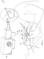
- FIGURE 1 illustrates a depiction of an embodiment of a ophthalmic surgery 100 using a surgical microscope 102 and contact lens 120.
- FIGURE 1 the use of contact lens 120 with a patient and a surgeon is depicted.
- FIGURE 1 is shown with surgical microscope 102 above the patient, it is noted that different orientations of the patient with respect to surgical microscope 102 may be practiced in different embodiments.
- contact lens 120 may be an indirect contact lens.
- the patient has an eye exposed using a speculum 114 that is in contact with contact lens 120, while the surgeon is viewing the fundus of the patient's eye using surgical microscope 102.
- a lens handle 112 is attached to contact lens 120 using a mounting clip 116 and is shown held in place by a surgical technician (or other personnel) to maintain alignment of a first optical axis 131 of contact lens 120 with a second optical axis 106 of surgical microscope 102, thereby enabling useful imaging for the surgeon to be maintained during surgery.
- Mounting clip 116 may be a single-use item to maintain sterility and may be disposable. It is noted that different means for supporting contact lens 120 may be used in different embodiments.
- the objective used with surgical microscope 102 may have a focal length of about 175mm to 225mm that may focuses on a focal plane of contact lens 120. As long as contact lens 120 remains free from condensation (fogging), the surgeon may be provided with field of view of the fundus of the eye via surgical microscope 102 and may safely proceed with any of a variety of ophthalmic surgical procedures (not shown).
- contact lens 120 when contact lens 120 is fogged, typically at a top exterior surface of contact lens 120 exposed to ambient conditions, the optical path of surgical microscope 102 may become obstructed and the surgeon can no longer view the fundus of the eye.
- fogging may occur relatively quickly and without warning during surgery and may even occur at moments when the surgeon is applying the utmost care and skill to perform minute operations in the fundus, such as membrane peeling and manipulation, drainage of subretinal fluid, endolaser application, among others. Therefore, fogging of contact lens 120 may result in unnecessary delays and interruptions and may represent a potentially serious risk during ophthalmic surgery.
- the ambient conditions in the operating room may be conducive to fogging of contact lens 120, such as humidity and low temperatures, which may vary locally at the location of contact lens 120 during surgery, resulting in unpredictable fogging behavior of contact lens 120.
- contact lens 120 is equipped with an anti-fogging device that delivers thermal energy to contact lens 120.
- the anti-fogging device may be activated to maintain visibility through contact lens 120 when ophthalmic surgery 100 is performed.
- the anti-fogging device comprises an air duct 108 that may be coupled to, or integrated with, lens handle 112 that is attached via mounting clip 116 to contact lens 120.
- lens handle 112 may be formed using stainless steel or polyether ether ketone (PEEK), which are materials that may be subject to autoclaving for disinfection.
- PEEK polyether ether ketone
- air duct 108 may terminate with an air nozzle 110 that is directed to the surface of contact lens 120 from an edge of contact lens 120. Air duct 108 may direct warmed air over the flange edge of contact lens 120 to reach the optical surface of contact lens 120.
- An air supply system may provide pressurized air at a desired temperature and a desired humidity to air nozzle 110 via fluid coupling through air duct 108.
- air nozzle 110 may be kept above the local ambient dew point and condensation (fogging) may be prevented.
- temperature, humidity, pressure, flow rate, or a combination of such parameters of the pressurized air flowing through air nozzle 110 may be regulated to a desired value.
- Air nozzle 110 or air duct 108 or both may be single-use items to maintain sterility and may be disposable. Because the dew point may be relatively low, a relatively small increase in temperature relative to the ambient temperature in the operating room of ophthalmic surgery 100 may suffice for the pressurized air to be anti-fogging at the surface of contact lens 120.
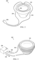
- FIGURE 1 In addition to the embodiment of the anti-fogging device depicted in FIGURE 1 , additional embodiments of the anti-fogging device may be implemented, as described below in the example implementations shown in FIGURES 2 and 3 .
- anti-fogging device 200 comprises an electrical heating element 202 shown formed as a circular ring at a peripheral portion of the surface of contact lens 120.
- electrical heating element 202 may be placed at other positions in contact with contact lens 120, such as attached to a housing of contact lens 120, attached to a ring-shaped flange of contact lens 120, or attached to mounting clip 116 of lens handle 112.
- Electrical heating element 202 is coupled at both ends to lead lines 204, which may be insulated wires that are attached to an external power source (not shown) via connector 206.
- lead lines 204 or connector 206 or both may be coupled to or integrated with lens handle 112, such that lead lines 204 are held in place using lens handle 112.
- Connector 206 may be an electrical plug or an electrical socket with two poles for each respective lead line 204.
- an electrical circuit including electrical heating element 202 is closed and current may flow through electrical heating element 202.
- Various different types of external power sources may be used with anti-fogging device 200, including direct current (DC) or alternating current (AC) sources.
- the external power source is included in surgical equipment present in the operating room such that connector 206 is plugged in to the surgical equipment.
- electrical heating element 202 will increase in temperature when the current flows through electrical heating element 202, thereby delivering a certain amount of thermal energy to the surface of contact lens 120 to prevent condensation (fogging) from occurring at the surface.
- electrical heating element 202 may be formed using various materials.
- a metallic material such as a nickel-chrome (Ni-Cr) alloy, an iron-chrome-aluminum (FeCrAl) alloy, or a copper-nickel (Cu-Ni) alloy, among others, may comprise at least a portion of electrical heating element 202.
- a transparent conductor such as indium tin oxide (ITO) may comprise at least a portion of electrical heating element 202 in order to minimize any optical effects of introducing anti-fogging device 200 to contact lens 120.
- ITO indium tin oxide
- electrical heating element 202 may comprise a ceramic material, such as a positive thermal coefficient (PTC) of resistance ceramic, including but not limited to barium titanate, lead titanate, and composites thereof.
- PTC positive thermal coefficient
- a conductive polymer such as a PTC rubber material, among others, may be used for electrical heating element 202. It is further noted that while a circular form is shown for electrical heating element 202 in FIGURE 2 , other forms or shapes may be used for electrical heating element 202.
- the power output of anti-fogging device 200 may be regulated to deliver a certain amount of power, to deliver a certain amount of heat, or to maintain a certain desired temperature, or a desired temperature difference, such as with the ambient air, at contact lens 120.
- a temperature sensor may additionally be included with contact lens 120 and may be used for regulation purposes in particular embodiments.
- a fixed amount of electrical current is continuously provided to electrical heating element 202 to provide enough thermal energy to maintain contact lens 120 at a temperature above the ambient dew point.
- the electrical current flowing through electrical heating element 202 may be relatively small, such as a few milliamperes, depending on the dimensions and resistivity of electrical heating element 202.
- anti-fogging device 300 comprises a fluid duct 302 in thermodynamic contact with contact lens 120.
- fluid duct 302 may be formed comprising a thermally conductive material, such a metal tube.
- Anti-fogging device 300 may comprise a coil formed with fluid duct 302 that is shaped to mate with contact lens 120.
- fluid duct 302 may be coupled to or integrated with lens handle 112, such that fluid duct 302 is held in place using lens handle 112.
- a heat transfer fluid may enter fluid duct 302 from a manifold 308 in direction 304 and may exit fluid duct 302 in direction 306 to manifold 308.
- Manifold 308 may further include a reservoir, a heating system, and a pump system (not shown) to enable circulation of the heat transfer fluid at a desired temperature through fluid duct 302 in order to warm contact lens 120 for anti-fogging purposes.
- the heat transfer fluid may be an aqueous solution, such as an aqueous saline solution or a sterile water solution.
- the temperature of the heat transfer fluid entering fluid duct 302 of antifogging device 300 may be regulated to deliver a certain amount of heat, or to maintain a certain desired temperature, or a desired temperature difference, such as with the ambient air, at contact lens 120. Accordingly, the temperature of the heat transfer fluid entering and exiting fluid duct 302 may be monitored and used for regulation purposes. In various arrangements, a fixed amount of thermal energy is continuously provided via the heat transfer fluid to fluid duct 302 to provide enough thermal energy to maintain contact lens 120 above the ambient dew point.
- Method 400 describes steps and procedures for using an anti-fogging device with contact lens 120 (see FIGURES 1 , 2, and 3 ) to view the fundus of an eye and to enable further surgical procedures based on the view of the fundus. It is noted that certain operations described in method 400 may be optional or may be rearranged in different arrangements. Method 400 may be performed by a surgeon or by other medical personnel. In some arrangements, at least certain portions of method 400 may be automated, for example using regulated control of temperature, as described above.
- Method 400 which is outside the scope of the claims, may begin, at step 402, by positioning a first optical axis of a surgical microscope along a second optical axis of an eye of a patient.
- step 404 an interior portion of the eye is viewed using a contact lens in contact with the eye.
- step 406 an anti-fogging device coupled to the contact lens is activated, such that the anti-fogging device delivers thermal energy to the contact lens.
- a contact lens for use with a surgical microscope may be equipped with an anti-fogging device to prevent obscuring the view of a surgeon due to condensation during ophthalmic surgery.
- the anti-fogging device may deliver thermal energy to a surface of the contact lens to heat the contact lens above an ambient dew point.
- the thermal energy may be delivered by an air duct with a fan nozzle, a fluid duct in thermodynamic contact with the contact lens circulating a heat transfer fluid, or generated with electrical energy to an electrical heating element disposed on the surface of the contact lens.
- the thermal or electrical energy may be delivered via a handle for supporting the contact lens during surgery.
Landscapes
- Health & Medical Sciences (AREA)
- Physics & Mathematics (AREA)
- Ophthalmology & Optometry (AREA)
- Life Sciences & Earth Sciences (AREA)
- General Health & Medical Sciences (AREA)
- Surgery (AREA)
- Optics & Photonics (AREA)
- General Physics & Mathematics (AREA)
- Public Health (AREA)
- Animal Behavior & Ethology (AREA)
- Heart & Thoracic Surgery (AREA)
- Veterinary Medicine (AREA)
- Biomedical Technology (AREA)
- Engineering & Computer Science (AREA)
- Nuclear Medicine, Radiotherapy & Molecular Imaging (AREA)
- Molecular Biology (AREA)
- Medical Informatics (AREA)
- Vascular Medicine (AREA)
- Pathology (AREA)
- Oral & Maxillofacial Surgery (AREA)
- Biophysics (AREA)
- Thermotherapy And Cooling Therapy Devices (AREA)
- Eye Examination Apparatus (AREA)
- Eyeglasses (AREA)
Claims (4)
- Ensemble de lentilles de contact pour la chirurgie ophtalmique, l'ensemble de lentilles de contact comprenant :une lentille de contact (120) ;un dispositif antibuée (200) couplé à la lentille de contact, le dispositif antibuée délivrant une énergie thermique à la lentille de contact lorsque celle-ci est utilisée au cours d'une chirurgie ophtalmique pour visualiser une partie intérieure de l'œil d'un patient à l'aide d'un microscope chirurgical ;caractérisé en ce que :le dispositif antibuée comprend en outre une poignée (112) pour soutenir la lentille de contact sur l'œil pendant l'opération chirurgicale ; etl'énergie électrique nécessaire à la production de l'énergie thermique est fournie par l'intermédiaire de fils conducteurs (204) fixés à la poignée.
- Ensemble de lentilles de contact selon la revendication 1, le dispositif antibuée (200) comprenant un élément chauffant électrique (202) disposé sur une surface de la lentille de contact pour générer de l'énergie thermique.
- Ensemble de lentilles de contact selon la revendication 2, l'élément chauffant électrique (202) comprenant un conducteur transparent.
- Ensemble de lentilles de contact selon la revendication 1, le dispositif antibuée comprenant un élément chauffant électrique (202) disposé sur un anneau entourant la lentille de contact.
Applications Claiming Priority (2)
| Application Number | Priority Date | Filing Date | Title |
|---|---|---|---|
| US201662332093P | 2016-05-05 | 2016-05-05 | |
| PCT/IB2017/052455 WO2017191538A1 (fr) | 2016-05-05 | 2017-04-27 | Prévention de la formation de buée pour lentilles de contact chirurgicales |
Publications (2)
| Publication Number | Publication Date |
|---|---|
| EP3429454A1 EP3429454A1 (fr) | 2019-01-23 |
| EP3429454B1 true EP3429454B1 (fr) | 2025-01-01 |
Family
ID=58709511
Family Applications (1)
| Application Number | Title | Priority Date | Filing Date |
|---|---|---|---|
| EP17723763.3A Active EP3429454B1 (fr) | 2016-05-05 | 2017-04-27 | Prévention de la formation de buée pour lentilles de contact chirurgicales |
Country Status (7)
| Country | Link |
|---|---|
| US (1) | US10172516B2 (fr) |
| EP (1) | EP3429454B1 (fr) |
| JP (1) | JP7123808B2 (fr) |
| CN (1) | CN109068976A (fr) |
| AU (1) | AU2017260847A1 (fr) |
| CA (1) | CA3018160A1 (fr) |
| WO (1) | WO2017191538A1 (fr) |
Families Citing this family (7)
| Publication number | Priority date | Publication date | Assignee | Title |
|---|---|---|---|---|
| CN110327014A (zh) * | 2019-07-09 | 2019-10-15 | 张国明 | 一种镜头防雾装置、镜头防雾显微镜及其使用方法 |
| US11166708B2 (en) | 2019-12-13 | 2021-11-09 | Alcon Inc. | Trans-scleral illumination system for vitreoretinal surgery |
| KR20220103877A (ko) * | 2021-06-03 | 2022-07-25 | 임채현 | 박막으로 구분된 공간을 갖는 액체 렌즈 구성을 통한 김서림 방지 장치 및 이를 포함하는 렌즈 |
| DE102021119297B4 (de) * | 2021-07-26 | 2025-03-27 | Carl Zeiss Meditec Ag | Kontaktloses Visualisierungssystem für ein Operationsmikroskop für die Augenchirurgie |
| TR2021017381A1 (tr) * | 2021-11-08 | 2023-05-22 | Ondokuz Mayis Üni̇versi̇tesi̇ | Oftalmik lensler için buğu önleyici aparat. |
| KR20260009315A (ko) * | 2023-05-15 | 2026-01-19 | 앰블러 서지컬, 엘엘씨 | 동공 확장기 어셈블리 |
| WO2025062215A1 (fr) * | 2023-09-20 | 2025-03-27 | Alcon Inc. | Prévention pneumatique de buée pour lentille ophtalmique |
Citations (1)
| Publication number | Priority date | Publication date | Assignee | Title |
|---|---|---|---|---|
| JP2003284686A (ja) * | 2002-03-28 | 2003-10-07 | Fuji Photo Optical Co Ltd | 内視鏡の撮像装置 |
Family Cites Families (14)
| Publication number | Priority date | Publication date | Assignee | Title |
|---|---|---|---|---|
| US4056310A (en) * | 1975-02-14 | 1977-11-01 | Olympus Optical Co., Ltd. | Method and device for ophthalmoscopy |
| AU1974897A (en) * | 1996-02-22 | 1997-09-10 | New Image Industries, Inc. | Apparatus and method for eliminating the fogging of intraoral camera images |
| JPH11133307A (ja) * | 1997-10-30 | 1999-05-21 | Sony Corp | 顕微鏡 |
| JP2001092000A (ja) * | 1999-09-21 | 2001-04-06 | Olympus Optical Co Ltd | 光学装置 |
| MXPA03006394A (es) * | 2001-01-18 | 2003-10-15 | Univ California | Instrumento quirurgico paraglaucoma minimamente invasivo y metodo. |
| US20090025125A1 (en) * | 2007-07-26 | 2009-01-29 | Wan-Chen Jou | Diving goggles with defogging device |
| DE102009013615A1 (de) * | 2009-03-17 | 2010-09-23 | Kaltenbach & Voigt Gmbh | Medizinisches, insbesondere zahnmedizinisches Diagnosegerät mit Bilderfassungsmitteln |
| CN102292014B (zh) * | 2009-07-23 | 2015-04-08 | 奥林巴斯医疗株式会社 | 内窥镜装置 |
| DE202011005230U1 (de) * | 2011-04-13 | 2011-09-14 | Björn Paech | Beheizbares System für die dem Operateur zugewandte Optik bei der mikroskopischen Chirurgie zum Schutz gegen das Beschlagen der Linse |
| US8939967B2 (en) | 2011-08-03 | 2015-01-27 | Alcon Lensx, Inc. | Patient interface defogger |
| CN202637254U (zh) * | 2012-06-26 | 2013-01-02 | 董金兰 | 一种眼科用微创电热凝止血器 |
| JP6133593B2 (ja) * | 2012-12-26 | 2017-05-24 | Hoya株式会社 | レンズ装着器具 |
| US10070989B2 (en) * | 2014-02-03 | 2018-09-11 | Mynosys Cellular Devices, Inc. | Capsulotomy cartridge |
| CN204086675U (zh) * | 2014-09-28 | 2015-01-07 | 昆明美菱光学仪器有限公司 | 一种防雾单筒望远镜 |
-
2017
- 2017-04-27 US US15/499,581 patent/US10172516B2/en active Active
- 2017-04-27 EP EP17723763.3A patent/EP3429454B1/fr active Active
- 2017-04-27 CN CN201780027113.2A patent/CN109068976A/zh active Pending
- 2017-04-27 CA CA3018160A patent/CA3018160A1/fr not_active Abandoned
- 2017-04-27 AU AU2017260847A patent/AU2017260847A1/en not_active Abandoned
- 2017-04-27 JP JP2018555605A patent/JP7123808B2/ja active Active
- 2017-04-27 WO PCT/IB2017/052455 patent/WO2017191538A1/fr not_active Ceased
Patent Citations (1)
| Publication number | Priority date | Publication date | Assignee | Title |
|---|---|---|---|---|
| JP2003284686A (ja) * | 2002-03-28 | 2003-10-07 | Fuji Photo Optical Co Ltd | 内視鏡の撮像装置 |
Also Published As
| Publication number | Publication date |
|---|---|
| JP2019514507A (ja) | 2019-06-06 |
| WO2017191538A1 (fr) | 2017-11-09 |
| EP3429454A1 (fr) | 2019-01-23 |
| AU2017260847A1 (en) | 2018-11-01 |
| CN109068976A (zh) | 2018-12-21 |
| CA3018160A1 (fr) | 2017-11-09 |
| US10172516B2 (en) | 2019-01-08 |
| JP7123808B2 (ja) | 2022-08-23 |
| US20170319062A1 (en) | 2017-11-09 |
Similar Documents
| Publication | Publication Date | Title |
|---|---|---|
| EP3429454B1 (fr) | Prévention de la formation de buée pour lentilles de contact chirurgicales | |
| US12070416B2 (en) | Systems and methods for the treatment of eye conditions | |
| US11065152B2 (en) | Systems and methods for the treatment of eye conditions | |
| US10456298B2 (en) | Systems and methods for the treatment of eye conditions | |
| ES2384211T3 (es) | Endoscopio con sistema eléctrico de calefacción | |
| JP2017533074A (ja) | 眼の疾患を手当てするシステムおよび方法 | |
| CN205031213U (zh) | 用于内窥镜镜头的防雾装置 | |
| WO2013008555A1 (fr) | Trocar à fonction chauffante et système associé | |
| KR101652417B1 (ko) | 복강경 장치 | |
| KR20160020297A (ko) | 감온변색 파코 관류 슬리브 | |
| Mandelcorn et al. | Unassisted scleral depression during vitrectomy surgery: two simple, cost-effective techniques | |
| CN113287051A (zh) | 能够通过微控制器对刚性内窥镜进行温度调节的防起雾系统 | |
| Demarinis et al. | Wide-angle viewing lens fogging: solving a common problem in vitreoretinal surgery | |
| CN213640811U (zh) | 一种可拆卸腹腔镜镜头防雾装置 | |
| CN208274629U (zh) | 一种腹部外科手术镜 | |
| US20200292396A1 (en) | Temperature indicator for fiber connectors and methods regarding same | |
| CN120531318A (zh) | 基于ptc热电效应的腹腔镜镜头智能温控系统 | |
| CN120916731A (zh) | 热眼润滑设备 | |
| CN111920462A (zh) | 一种防止手术镜起雾的牵开保护器 |
Legal Events
| Date | Code | Title | Description |
|---|---|---|---|
| STAA | Information on the status of an ep patent application or granted ep patent |
Free format text: STATUS: UNKNOWN |
|
| STAA | Information on the status of an ep patent application or granted ep patent |
Free format text: STATUS: THE INTERNATIONAL PUBLICATION HAS BEEN MADE |
|
| PUAI | Public reference made under article 153(3) epc to a published international application that has entered the european phase |
Free format text: ORIGINAL CODE: 0009012 |
|
| STAA | Information on the status of an ep patent application or granted ep patent |
Free format text: STATUS: REQUEST FOR EXAMINATION WAS MADE |
|
| 17P | Request for examination filed |
Effective date: 20181016 |
|
| AK | Designated contracting states |
Kind code of ref document: A1 Designated state(s): AL AT BE BG CH CY CZ DE DK EE ES FI FR GB GR HR HU IE IS IT LI LT LU LV MC MK MT NL NO PL PT RO RS SE SI SK SM TR |
|
| AX | Request for extension of the european patent |
Extension state: BA ME |
|
| DAV | Request for validation of the european patent (deleted) | ||
| DAX | Request for extension of the european patent (deleted) | ||
| RAP1 | Party data changed (applicant data changed or rights of an application transferred) |
Owner name: ALCON INC. |
|
| STAA | Information on the status of an ep patent application or granted ep patent |
Free format text: STATUS: EXAMINATION IS IN PROGRESS |
|
| 17Q | First examination report despatched |
Effective date: 20210219 |
|
| P01 | Opt-out of the competence of the unified patent court (upc) registered |
Effective date: 20230507 |
|
| GRAP | Despatch of communication of intention to grant a patent |
Free format text: ORIGINAL CODE: EPIDOSNIGR1 |
|
| STAA | Information on the status of an ep patent application or granted ep patent |
Free format text: STATUS: GRANT OF PATENT IS INTENDED |
|
| INTG | Intention to grant announced |
Effective date: 20240726 |
|
| GRAS | Grant fee paid |
Free format text: ORIGINAL CODE: EPIDOSNIGR3 |
|
| GRAA | (expected) grant |
Free format text: ORIGINAL CODE: 0009210 |
|
| STAA | Information on the status of an ep patent application or granted ep patent |
Free format text: STATUS: THE PATENT HAS BEEN GRANTED |
|
| AK | Designated contracting states |
Kind code of ref document: B1 Designated state(s): AL AT BE BG CH CY CZ DE DK EE ES FI FR GB GR HR HU IE IS IT LI LT LU LV MC MK MT NL NO PL PT RO RS SE SI SK SM TR |
|
| REG | Reference to a national code |
Ref country code: GB Ref legal event code: FG4D |
|
| REG | Reference to a national code |
Ref country code: DE Ref legal event code: R096 Ref document number: 602017087072 Country of ref document: DE |
|
| REG | Reference to a national code |
Ref country code: CH Ref legal event code: EP |
|
| REG | Reference to a national code |
Ref country code: IE Ref legal event code: FG4D Ref country code: NL Ref legal event code: FP |
|
| REG | Reference to a national code |
Ref country code: LT Ref legal event code: MG9D |
|
| REG | Reference to a national code |
Ref country code: AT Ref legal event code: MK05 Ref document number: 1755387 Country of ref document: AT Kind code of ref document: T Effective date: 20250101 |
|
| PG25 | Lapsed in a contracting state [announced via postgrant information from national office to epo] |
Ref country code: FI Free format text: LAPSE BECAUSE OF FAILURE TO SUBMIT A TRANSLATION OF THE DESCRIPTION OR TO PAY THE FEE WITHIN THE PRESCRIBED TIME-LIMIT Effective date: 20250101 |
|
| PG25 | Lapsed in a contracting state [announced via postgrant information from national office to epo] |
Ref country code: PL Free format text: LAPSE BECAUSE OF FAILURE TO SUBMIT A TRANSLATION OF THE DESCRIPTION OR TO PAY THE FEE WITHIN THE PRESCRIBED TIME-LIMIT Effective date: 20250101 |
|
| PGFP | Annual fee paid to national office [announced via postgrant information from national office to epo] |
Ref country code: DE Payment date: 20250319 Year of fee payment: 9 |
|
| PG25 | Lapsed in a contracting state [announced via postgrant information from national office to epo] |
Ref country code: ES Free format text: LAPSE BECAUSE OF FAILURE TO SUBMIT A TRANSLATION OF THE DESCRIPTION OR TO PAY THE FEE WITHIN THE PRESCRIBED TIME-LIMIT Effective date: 20250101 |
|
| PG25 | Lapsed in a contracting state [announced via postgrant information from national office to epo] |
Ref country code: IS Free format text: LAPSE BECAUSE OF FAILURE TO SUBMIT A TRANSLATION OF THE DESCRIPTION OR TO PAY THE FEE WITHIN THE PRESCRIBED TIME-LIMIT Effective date: 20250501 Ref country code: NO Free format text: LAPSE BECAUSE OF FAILURE TO SUBMIT A TRANSLATION OF THE DESCRIPTION OR TO PAY THE FEE WITHIN THE PRESCRIBED TIME-LIMIT Effective date: 20250401 |
|
| PGFP | Annual fee paid to national office [announced via postgrant information from national office to epo] |
Ref country code: IT Payment date: 20250326 Year of fee payment: 9 |
|
| PG25 | Lapsed in a contracting state [announced via postgrant information from national office to epo] |
Ref country code: HR Free format text: LAPSE BECAUSE OF FAILURE TO SUBMIT A TRANSLATION OF THE DESCRIPTION OR TO PAY THE FEE WITHIN THE PRESCRIBED TIME-LIMIT Effective date: 20250101 |
|
| PG25 | Lapsed in a contracting state [announced via postgrant information from national office to epo] |
Ref country code: PT Free format text: LAPSE BECAUSE OF FAILURE TO SUBMIT A TRANSLATION OF THE DESCRIPTION OR TO PAY THE FEE WITHIN THE PRESCRIBED TIME-LIMIT Effective date: 20250502 Ref country code: LV Free format text: LAPSE BECAUSE OF FAILURE TO SUBMIT A TRANSLATION OF THE DESCRIPTION OR TO PAY THE FEE WITHIN THE PRESCRIBED TIME-LIMIT Effective date: 20250101 |
|
| PG25 | Lapsed in a contracting state [announced via postgrant information from national office to epo] |
Ref country code: BG Free format text: LAPSE BECAUSE OF FAILURE TO SUBMIT A TRANSLATION OF THE DESCRIPTION OR TO PAY THE FEE WITHIN THE PRESCRIBED TIME-LIMIT Effective date: 20250101 Ref country code: GR Free format text: LAPSE BECAUSE OF FAILURE TO SUBMIT A TRANSLATION OF THE DESCRIPTION OR TO PAY THE FEE WITHIN THE PRESCRIBED TIME-LIMIT Effective date: 20250402 |
|
| PG25 | Lapsed in a contracting state [announced via postgrant information from national office to epo] |
Ref country code: AT Free format text: LAPSE BECAUSE OF FAILURE TO SUBMIT A TRANSLATION OF THE DESCRIPTION OR TO PAY THE FEE WITHIN THE PRESCRIBED TIME-LIMIT Effective date: 20250101 |
|
| PG25 | Lapsed in a contracting state [announced via postgrant information from national office to epo] |
Ref country code: CZ Free format text: LAPSE BECAUSE OF FAILURE TO SUBMIT A TRANSLATION OF THE DESCRIPTION OR TO PAY THE FEE WITHIN THE PRESCRIBED TIME-LIMIT Effective date: 20250101 |
|
| PG25 | Lapsed in a contracting state [announced via postgrant information from national office to epo] |
Ref country code: SE Free format text: LAPSE BECAUSE OF FAILURE TO SUBMIT A TRANSLATION OF THE DESCRIPTION OR TO PAY THE FEE WITHIN THE PRESCRIBED TIME-LIMIT Effective date: 20250101 |
|
| REG | Reference to a national code |
Ref country code: DE Ref legal event code: R097 Ref document number: 602017087072 Country of ref document: DE |
|
| PG25 | Lapsed in a contracting state [announced via postgrant information from national office to epo] |
Ref country code: SM Free format text: LAPSE BECAUSE OF FAILURE TO SUBMIT A TRANSLATION OF THE DESCRIPTION OR TO PAY THE FEE WITHIN THE PRESCRIBED TIME-LIMIT Effective date: 20250101 |
|
| PG25 | Lapsed in a contracting state [announced via postgrant information from national office to epo] |
Ref country code: DK Free format text: LAPSE BECAUSE OF FAILURE TO SUBMIT A TRANSLATION OF THE DESCRIPTION OR TO PAY THE FEE WITHIN THE PRESCRIBED TIME-LIMIT Effective date: 20250101 |
|
| PG25 | Lapsed in a contracting state [announced via postgrant information from national office to epo] |
Ref country code: EE Free format text: LAPSE BECAUSE OF FAILURE TO SUBMIT A TRANSLATION OF THE DESCRIPTION OR TO PAY THE FEE WITHIN THE PRESCRIBED TIME-LIMIT Effective date: 20250101 |
|
| PG25 | Lapsed in a contracting state [announced via postgrant information from national office to epo] |
Ref country code: RO Free format text: LAPSE BECAUSE OF FAILURE TO SUBMIT A TRANSLATION OF THE DESCRIPTION OR TO PAY THE FEE WITHIN THE PRESCRIBED TIME-LIMIT Effective date: 20250101 |
|
| PG25 | Lapsed in a contracting state [announced via postgrant information from national office to epo] |
Ref country code: SK Free format text: LAPSE BECAUSE OF FAILURE TO SUBMIT A TRANSLATION OF THE DESCRIPTION OR TO PAY THE FEE WITHIN THE PRESCRIBED TIME-LIMIT Effective date: 20250101 |
|
| PLBE | No opposition filed within time limit |
Free format text: ORIGINAL CODE: 0009261 |
|
| STAA | Information on the status of an ep patent application or granted ep patent |
Free format text: STATUS: NO OPPOSITION FILED WITHIN TIME LIMIT |
|
| REG | Reference to a national code |
Ref country code: CH Ref legal event code: L10 Free format text: ST27 STATUS EVENT CODE: U-0-0-L10-L00 (AS PROVIDED BY THE NATIONAL OFFICE) Effective date: 20251112 |
|
| REG | Reference to a national code |
Ref country code: CH Ref legal event code: H13 Free format text: ST27 STATUS EVENT CODE: U-0-0-H10-H13 (AS PROVIDED BY THE NATIONAL OFFICE) Effective date: 20251125 |
|
| 26N | No opposition filed |
Effective date: 20251002 |
|
| PG25 | Lapsed in a contracting state [announced via postgrant information from national office to epo] |
Ref country code: LU Free format text: LAPSE BECAUSE OF NON-PAYMENT OF DUE FEES Effective date: 20250427 |
|
| PG25 | Lapsed in a contracting state [announced via postgrant information from national office to epo] |
Ref country code: MC Free format text: LAPSE BECAUSE OF FAILURE TO SUBMIT A TRANSLATION OF THE DESCRIPTION OR TO PAY THE FEE WITHIN THE PRESCRIBED TIME-LIMIT Effective date: 20250101 |
|
| GBPC | Gb: european patent ceased through non-payment of renewal fee |
Effective date: 20250427 |
|
| REG | Reference to a national code |
Ref country code: BE Ref legal event code: MM Effective date: 20250430 |
|
| PG25 | Lapsed in a contracting state [announced via postgrant information from national office to epo] |
Ref country code: GB Free format text: LAPSE BECAUSE OF NON-PAYMENT OF DUE FEES Effective date: 20250427 |
|
| PG25 | Lapsed in a contracting state [announced via postgrant information from national office to epo] |
Ref country code: FR Free format text: LAPSE BECAUSE OF NON-PAYMENT OF DUE FEES Effective date: 20250430 |
|
| PG25 | Lapsed in a contracting state [announced via postgrant information from national office to epo] |
Ref country code: BE Free format text: LAPSE BECAUSE OF NON-PAYMENT OF DUE FEES Effective date: 20250430 |
|
| PG25 | Lapsed in a contracting state [announced via postgrant information from national office to epo] |
Ref country code: CH Free format text: LAPSE BECAUSE OF NON-PAYMENT OF DUE FEES Effective date: 20250430 |
|
| PG25 | Lapsed in a contracting state [announced via postgrant information from national office to epo] |
Ref country code: IE Free format text: LAPSE BECAUSE OF NON-PAYMENT OF DUE FEES Effective date: 20250427 |
|
| PGFP | Annual fee paid to national office [announced via postgrant information from national office to epo] |
Ref country code: NL Payment date: 20260327 Year of fee payment: 10 |