EP3429498B1 - Système de suivi optique - Google Patents
Système de suivi optique Download PDFInfo
- Publication number
- EP3429498B1 EP3429498B1 EP17709962.9A EP17709962A EP3429498B1 EP 3429498 B1 EP3429498 B1 EP 3429498B1 EP 17709962 A EP17709962 A EP 17709962A EP 3429498 B1 EP3429498 B1 EP 3429498B1
- Authority
- EP
- European Patent Office
- Prior art keywords
- camera
- anatomical structure
- computer
- medical
- data
- Prior art date
- Legal status (The legal status is an assumption and is not a legal conclusion. Google has not performed a legal analysis and makes no representation as to the accuracy of the status listed.)
- Active
Links
Images




Classifications
-
- G—PHYSICS
- G06—COMPUTING OR CALCULATING; COUNTING
- G06T—IMAGE DATA PROCESSING OR GENERATION, IN GENERAL
- G06T7/00—Image analysis
- G06T7/20—Analysis of motion
- G06T7/292—Multi-camera tracking
-
- A—HUMAN NECESSITIES
- A61—MEDICAL OR VETERINARY SCIENCE; HYGIENE
- A61B—DIAGNOSIS; SURGERY; IDENTIFICATION
- A61B34/00—Computer-aided surgery; Manipulators or robots specially adapted for use in surgery
- A61B34/20—Surgical navigation systems; Devices for tracking or guiding surgical instruments, e.g. for frameless stereotaxis
-
- A—HUMAN NECESSITIES
- A61—MEDICAL OR VETERINARY SCIENCE; HYGIENE
- A61B—DIAGNOSIS; SURGERY; IDENTIFICATION
- A61B90/00—Instruments, implements or accessories specially adapted for surgery or diagnosis and not covered by any of the groups A61B1/00 - A61B50/00, e.g. for luxation treatment or for protecting wound edges
- A61B90/36—Image-producing devices or illumination devices not otherwise provided for
- A61B90/361—Image-producing devices, e.g. surgical cameras
-
- A—HUMAN NECESSITIES
- A61—MEDICAL OR VETERINARY SCIENCE; HYGIENE
- A61B—DIAGNOSIS; SURGERY; IDENTIFICATION
- A61B90/00—Instruments, implements or accessories specially adapted for surgery or diagnosis and not covered by any of the groups A61B1/00 - A61B50/00, e.g. for luxation treatment or for protecting wound edges
- A61B90/39—Markers, e.g. radio-opaque or breast lesions markers
-
- G—PHYSICS
- G06—COMPUTING OR CALCULATING; COUNTING
- G06T—IMAGE DATA PROCESSING OR GENERATION, IN GENERAL
- G06T7/00—Image analysis
- G06T7/70—Determining position or orientation of objects or cameras
-
- A—HUMAN NECESSITIES
- A61—MEDICAL OR VETERINARY SCIENCE; HYGIENE
- A61B—DIAGNOSIS; SURGERY; IDENTIFICATION
- A61B34/00—Computer-aided surgery; Manipulators or robots specially adapted for use in surgery
- A61B34/20—Surgical navigation systems; Devices for tracking or guiding surgical instruments, e.g. for frameless stereotaxis
- A61B2034/2046—Tracking techniques
- A61B2034/2055—Optical tracking systems
-
- A—HUMAN NECESSITIES
- A61—MEDICAL OR VETERINARY SCIENCE; HYGIENE
- A61B—DIAGNOSIS; SURGERY; IDENTIFICATION
- A61B34/00—Computer-aided surgery; Manipulators or robots specially adapted for use in surgery
- A61B34/20—Surgical navigation systems; Devices for tracking or guiding surgical instruments, e.g. for frameless stereotaxis
- A61B2034/2046—Tracking techniques
- A61B2034/2055—Optical tracking systems
- A61B2034/2057—Details of tracking cameras
-
- A—HUMAN NECESSITIES
- A61—MEDICAL OR VETERINARY SCIENCE; HYGIENE
- A61B—DIAGNOSIS; SURGERY; IDENTIFICATION
- A61B34/00—Computer-aided surgery; Manipulators or robots specially adapted for use in surgery
- A61B34/20—Surgical navigation systems; Devices for tracking or guiding surgical instruments, e.g. for frameless stereotaxis
- A61B2034/2046—Tracking techniques
- A61B2034/2065—Tracking using image or pattern recognition
-
- A—HUMAN NECESSITIES
- A61—MEDICAL OR VETERINARY SCIENCE; HYGIENE
- A61B—DIAGNOSIS; SURGERY; IDENTIFICATION
- A61B90/00—Instruments, implements or accessories specially adapted for surgery or diagnosis and not covered by any of the groups A61B1/00 - A61B50/00, e.g. for luxation treatment or for protecting wound edges
- A61B90/36—Image-producing devices or illumination devices not otherwise provided for
- A61B2090/363—Use of fiducial points
-
- A—HUMAN NECESSITIES
- A61—MEDICAL OR VETERINARY SCIENCE; HYGIENE
- A61B—DIAGNOSIS; SURGERY; IDENTIFICATION
- A61B90/00—Instruments, implements or accessories specially adapted for surgery or diagnosis and not covered by any of the groups A61B1/00 - A61B50/00, e.g. for luxation treatment or for protecting wound edges
- A61B90/36—Image-producing devices or illumination devices not otherwise provided for
- A61B2090/364—Correlation of different images or relation of image positions in respect to the body
-
- A—HUMAN NECESSITIES
- A61—MEDICAL OR VETERINARY SCIENCE; HYGIENE
- A61B—DIAGNOSIS; SURGERY; IDENTIFICATION
- A61B90/00—Instruments, implements or accessories specially adapted for surgery or diagnosis and not covered by any of the groups A61B1/00 - A61B50/00, e.g. for luxation treatment or for protecting wound edges
- A61B90/36—Image-producing devices or illumination devices not otherwise provided for
- A61B90/37—Surgical systems with images on a monitor during operation
- A61B2090/371—Surgical systems with images on a monitor during operation with simultaneous use of two cameras
-
- A—HUMAN NECESSITIES
- A61—MEDICAL OR VETERINARY SCIENCE; HYGIENE
- A61B—DIAGNOSIS; SURGERY; IDENTIFICATION
- A61B90/00—Instruments, implements or accessories specially adapted for surgery or diagnosis and not covered by any of the groups A61B1/00 - A61B50/00, e.g. for luxation treatment or for protecting wound edges
- A61B90/39—Markers, e.g. radio-opaque or breast lesions markers
- A61B2090/3937—Visible markers
-
- A—HUMAN NECESSITIES
- A61—MEDICAL OR VETERINARY SCIENCE; HYGIENE
- A61B—DIAGNOSIS; SURGERY; IDENTIFICATION
- A61B90/00—Instruments, implements or accessories specially adapted for surgery or diagnosis and not covered by any of the groups A61B1/00 - A61B50/00, e.g. for luxation treatment or for protecting wound edges
- A61B90/39—Markers, e.g. radio-opaque or breast lesions markers
- A61B2090/3983—Reference marker arrangements for use with image guided surgery
-
- A—HUMAN NECESSITIES
- A61—MEDICAL OR VETERINARY SCIENCE; HYGIENE
- A61B—DIAGNOSIS; SURGERY; IDENTIFICATION
- A61B90/00—Instruments, implements or accessories specially adapted for surgery or diagnosis and not covered by any of the groups A61B1/00 - A61B50/00, e.g. for luxation treatment or for protecting wound edges
- A61B90/20—Surgical microscopes characterised by non-optical aspects
-
- G—PHYSICS
- G02—OPTICS
- G02B—OPTICAL ELEMENTS, SYSTEMS OR APPARATUS
- G02B21/00—Microscopes
- G02B21/0004—Microscopes specially adapted for specific applications
- G02B21/0012—Surgical microscopes
-
- G—PHYSICS
- G06—COMPUTING OR CALCULATING; COUNTING
- G06T—IMAGE DATA PROCESSING OR GENERATION, IN GENERAL
- G06T2207/00—Indexing scheme for image analysis or image enhancement
- G06T2207/30—Subject of image; Context of image processing
- G06T2207/30204—Marker
Definitions
- the present part of the invention relates to a computer program for tracking a spatial position of at least one medical instrument within a medical workspace, a corresponding non-transitory program storage medium storing such a program and a computer for executing the program as well as a corresponding tracking system determining the spatial position of at least one medical instrument within a medical workspace.
- Known tracking systems that utilize an optical video camera for tracking purposes are known, for example from US 8,657,809 .
- This system comprises a camera which is mounted to the head of a patient. In order for the camera to track a surgical tool above the patient, the line of sight between the camera and the tool must not be interrupted.
- US 6,434,416 refers to a surgical microscope which enables the position of a medical instrument used under the surgical microscope to be sensed.
- WO 2015/024600 discloses a technique for determining a transformation between a navigation reference coordinate system and an image coordinate system.
- the present invention allows for a more reliable approach to track a medical instrument within a medical workspace via a video camera, which even allows for a registration of an image dataset.
- the disclosed tracking system and corresponding computer program stored on a non-transitory computer readable storage medium encompass determining the spatial position of at least one medical instrument within a medical workspace by means of a video camera that forms part of a microscope looking down on a patient lying on a patient couch.
- the spatial position of the microscope video camera with respect to the anatomical structure is in turn determined with the help of a further video camera that is either fixed to the anatomical structure or to the microscope, or may even be independently installed within the operating theater. From the determined relative position or relative pose of the instrument and the microscope, and from the determined relative position of the microscope and the anatomical structure, the relative position of the instrument and the anatomical structure is then calculated.
- the invention reaches the aforementioned object by providing, in a first aspect, a system for tracking a spatial position of at least one medical instrument within a medical workspace.
- the system comprises a computer having at least one processor adapted to execute, the following exemplary steps.
- instrument position data is acquired which describes a spatial position of at least one medical instrument with respect to a first camera by an evaluation of at least one image provided by the at least one first camera, which shows the at least one medical instrument.
- the at least one instrument may comprise specific tracking markers adapted to be recognized by a video camera. Such specific tracking markers are discussed in Parts II, III and IV and may form part of the invention discussed in Part I, but may also be considered as separate inventions.
- the at least one instrument may also be recognized by optical characteristics such as an identifiable structure or shape.
- the values for the focus and the zoom of the camera can provide data for determining the spatial position of an instrument and/or anatomical structure with respect to a camera directed to this instrument.
- camera position data is acquired which describes a spatial position of the at least one first camera with respect to an anatomical structure using a second camera and at least one optical tracking marker (6, 7) adapted to be recognized by the second camera, wherein
- the instrument position data and the camera position data is used to determine tracking data that describes the spatial position of the at least one medical instrument with respect to the anatomical structure.
- the first camera is rigidly coupled to a medical microscope targeted on the medical workspace, wherein the first camera is in particular a microscope-integrated camera.
- a camera that is assigned a medical microscope that may in particular look down on a patient lying on a patient couch, it is possible to advantageously use of an illumination lamp of the microscope illuminating the workspace and therefore also the anatomical structure and the at least one medical instrument. Since such camera is fixedly attached to the microscope, the position of any object seen by the microscope's camera can be determined within a coordinate system assigned to the microscope.
- the first camera may also be freely movable relative to the anatomical structure.
- a mobile microscope with an integrated video camera could be provided and advantageously arranged at any desired position next to the medical workspace.
- At least one second camera is then used for determining the relative position between the first camera and the anatomical structure, which may either be rigidly coupled to the first camera or to the anatomical structure, wherein the corresponding tracking marker to be seen by the at least one second camera is correspondingly coupled in a rigid manner either to the anatomical structure or the first camera.
- Both, the second camera and the tracking marker to be seen by the second camera may be located away from the medical workspace so that possible interruptions of the line of sight between the camera and the tracking marker can be prevented.
- a pivoting mechanism may be provided to allow the second camera to be pivoted between at least two known orientations (i.e.
- the first orientation with respect to the second orientation is known), one orientation being directed towards the workspace (which allows the camera to detect a medical instrument during a registration procedure) and a second orientation being directed towards the tracking marker coupled to the first camera (which is necessary for determining the relative position between the first camera and the anatomical structure).
- the disclosed system may further be adapted to perform a method comprising a (for example fourth) exemplary step of acquiring registration data that describes a spatial correspondence of a pre-acquired dataset of the anatomical structure and the actual anatomical structure within the medical workspace.
- image registration allows for calculating and displaying a virtual representation of the at least one medical instrument in a correct spatial arrangement relative to a two-dimensional or three-dimensional image obtained from a pre-acquired image dataset of the patient showing the anatomical structure.
- the pre-acquired image dataset may be of any conceivable type and may specifically contain CT-images, MR-images and/or ultrasound images.
- any of the tracking markers used in the context of the apparatus disclosed herein may comprise a two-dimensional optical pattern that can be detected by an optical camera.
- the optical pattern may provide a checkerboard pattern that may be optically recognized within the visible range of light.
- the step of acquiring registration data may involve at least one registration procedure selected form the list containing
- the invention is directed to a non-transitory computer-readable storage medium storing a computer program which, when executed on at least one processor of at least one computer or loaded into the memory of at least one computer, causes the at least one computer to perform a method that has been described further above.
- the invention is directed to at least one computer comprising the non-transitory computer-readable program storage medium according to the second aspect.
- a feature of one embodiment which has the same or a similar function to another feature of another embodiment can be exchanged with said other feature, and a feature of one embodiment which adds an additional function to another embodiment can for example be added to said other embodiment.
- computer program elements can be embodied by hardware and/or software (this includes firmware, resident software, micro-code, etc.).
- computer program elements can take the form of a computer program product which can be embodied by a computer-usable, for example computer-readable data storage medium comprising computer-usable, for example computer-readable program instructions, "code” or a "computer program” embodied in said data storage medium for use on or in connection with the instruction-executing system.
- Such a system can be a computer; a computer can be a data processing device comprising means for executing the computer program elements and/or the program in accordance with the invention, for example a data processing device comprising a digital processor (central processing unit or CPU) which executes the computer program elements, and optionally a volatile memory (for example a random access memory or RAM) for storing data used for and/or produced by executing the computer program elements.
- a computer-usable, for example computer-readable data storage medium can be any data storage medium which can include, store, communicate, propagate or transport the program for use on or in connection with the instruction-executing system, apparatus or device.
- the computer-usable, for example computer-readable data storage medium can for example be, but is not limited to, an electronic, magnetic, optical, electromagnetic, infrared or semiconductor system, apparatus or device or a medium of propagation such as for example the Internet.
- the computer-usable or computer-readable data storage medium could even for example be paper or another suitable medium onto which the program is printed, since the program could be electronically captured, for example by optically scanning the paper or other suitable medium, and then compiled, interpreted or otherwise processed in a suitable manner.
- the data storage medium is preferably a non-volatile data storage medium.
- the computer program product and any software and/or hardware described here form the various means for performing the functions of the invention in the example embodiments.
- the computer and/or data processing device can for example include a guidance information device which includes means for outputting guidance information.
- the guidance information can be outputted, for example to a user, visually by a visual indicating means (for example, a monitor and/or a lamp) and/or acoustically by an acoustic indicating means (for example, a loudspeaker and/or a digital speech output device) and/or tactilely by a tactile indicating means (for example, a vibrating element or a vibration element incorporated into an instrument).
- a computer is a technical computer which for example comprises technical, for example tangible components, for example mechanical and/or electronic components. Any device mentioned as such in this document is a technical and for example tangible device.
- the method in accordance with the invention is for example a computer implemented method.
- all the steps or merely some of the steps (i.e. less than the total number of steps) of the method in accordance with the invention can be executed by a computer (for example, at least one computer).
- An embodiment of the computer implemented method is a use of the computer for performing a data processing method.
- An embodiment of the computer implemented method is a method concerning the operation of the computer such that the computer is operated to perform one, more or all steps of the method.
- the computer for example comprises at least one processor and for example at least one memory in order to (technically) process the data, for example electronically and/or optically.
- the processor being for example made of a substance or composition which is a semiconductor, for example at least partly n- and/or p-doped semiconductor, for example at least one of II-, III-, IV-, V-, VI-semiconductor material, for example (doped) silicon and/or gallium arsenide.
- the calculating steps described are for example performed by a computer. Determining steps or calculating steps are for example steps of determining data within the framework of the technical method, for example within the framework of a program.
- a computer is for example any kind of data processing device, for example electronic data processing device.
- a computer can be a device which is generally thought of as such, for example desktop PCs, notebooks, netbooks, etc., but can also be any programmable apparatus, such as for example a mobile phone or an embedded processor.
- a computer can for example comprise a system (network) of "sub-computers", wherein each sub-computer represents a computer in its own right.
- the term "computer” includes a cloud computer, for example a cloud server.
- the term "cloud computer” includes a cloud computer system which for example comprises a system of at least one cloud computer and for example a plurality of operatively interconnected cloud computers such as a server farm.
- Such a cloud computer is preferably connected to a wide area network such as the world wide web (WWW) and located in a so-called cloud of computers which are all connected to the world wide web.
- WWW world wide web
- Such an infrastructure is used for "cloud computing", which describes computation, software, data access and storage services which do not require the end user to know the physical location and/or configuration of the computer delivering a specific service.
- the term "cloud” is used in this respect as a metaphor for the Internet (world wide web).
- the cloud provides computing infrastructure as a service (laaS).
- the cloud computer can function as a virtual host for an operating system and/or data processing application which is used to execute the method of the invention.
- the cloud computer is for example an elastic compute cloud (EC2) as provided by Amazon Web ServicesTM.
- a computer for example comprises interfaces in order to receive or output data and/or perform an analogue-to-digital conversion.
- the data are for example data which represent physical properties and/or which are generated from technical signals.
- the technical signals are for example generated by means of (technical) detection devices (such as for example devices for detecting marker devices) and/or (technical) analytical devices (such as for example devices for performing imaging methods), wherein the technical signals are for example electrical or optical signals.
- the technical signals for example represent the data received or outputted by the computer.
- the computer is preferably operatively coupled to a display device which allows information outputted by the computer to be displayed, for example to a user.
- a display device is an augmented reality device (also referred to as augmented reality glasses) which can be used as "goggles" for navigating.
- augmented reality glasses also referred to as augmented reality glasses
- Google Glass a trademark of Google, Inc.
- An augmented reality device can be used both to input information into the computer by user interaction and to display information outputted by the computer.
- a display device would be a standard computer monitor comprising for example a liquid crystal display operatively coupled to the computer for receiving display control data from the computer for generating signals used to display image information content on the display device.
- a specific embodiment of such a computer monitor is a digital lightbox.
- the monitor may also be the monitor of a portable, for example handheld, device such as a smart phone or personal digital assistant or digital media player.
- the expression "acquiring data” for example encompasses (within the framework of a computer implemented method) the scenario in which the data are determined by the computer implemented method or program. Determining data for example encompasses measuring physical quantities and transforming the measured values into data, for example digital data, and/or computing the data by means of a computer and for example within the framework of the method in accordance with the invention.
- the meaning of "acquiring data” also for example encompasses the scenario in which the data are received or retrieved by the computer implemented method or program, for example from another program, a previous method step or a data storage medium, for example for further processing by the computer implemented method or program.
- the expression "acquiring data” can therefore also for example mean waiting to receive data and/or receiving the data.
- the received data can for example be inputted via an interface.
- the expression "acquiring data” can also mean that the computer implemented method or program performs steps in order to (actively) receive or retrieve the data from a data source, for instance a data storage medium (such as for example a ROM, RAM, database, hard drive, etc.), or via the interface (for instance, from another computer or a network).
- the data acquired by the disclosed method or device, respectively may be acquired from a database located in a data storage device which is operably to a computer for data transfer between the database and the computer, for example from the database to the computer.
- the computer acquires the data for use as an input for steps of determining data.
- the determined data can be output again to the same or another database to be stored for later use.
- the database or database used for implementing the disclosed method can be located on network data storage device or a network server (for example, a cloud data storage device or a cloud server) or a local data storage device (such as a mass storage device operably connected to at least one computer executing the disclosed method).
- the data can be made "ready for use” by performing an additional step before the acquiring step.
- the data are generated in order to be acquired.
- the data are for example detected or captured (for example by an analytical device).
- the data are inputted in accordance with the additional step, for instance via interfaces.
- the data generated can for example be inputted (for instance into the computer).
- the data can also be provided by performing the additional step of storing the data in a data storage medium (such as for example a ROM, RAM, CD and/or hard drive), such that they are ready for use within the framework of the method or program in accordance with the invention.
- a data storage medium such as for example a ROM, RAM, CD and/or hard drive
- the step of "acquiring data” can therefore also involve commanding a device to obtain and/or provide the data to be acquired.
- the acquiring step does not involve an invasive step which would represent a substantial physical interference with the body, requiring professional medical expertise to be carried out and entailing a substantial health risk even when carried out with the required professional care and expertise.
- the step of acquiring data does not involve a surgical step and in particular does not involve a step of treating a human or animal body using surgery or therapy.
- the data are denoted (i.e. referred to) as "XY data” and the like and are defined in terms of the information which they describe, which is then preferably referred to as "XY information" and the like.
- the n-dimensional image of a body is registered when the spatial location of each point of an actual object within a space, for example a body part in an operating theatre, is assigned an image data point of an image (CT, MR, etc.) stored in a navigation system.
- CT computed tomography
- MR magnetic resonance
- Image registration is the process of transforming different sets of data into one coordinate system.
- the data can be multiple photographs and/or data from different sensors, different times or different viewpoints. It is used in computer vision, medical imaging and in compiling and analyzing images and data from satellites. Registration is necessary in order to be able to compare or integrate the data obtained from these different measurements.
- the invention also relates to a program which, when running on a computer, causes the computer to perform one or more or all of the method steps described herein and/or to a program storage medium on which the program is stored (in particular in a non-transitory form) and/or to a computer comprising said program storage medium and/or to a (physical, for example electrical, for example technically generated) signal wave, for example a digital signal wave, carrying information which represents the program, for example the aforementioned program, which for example comprises code means which are adapted to perform any or all of the method steps described herein.
- the invention also relates to a navigation system for computer-assisted surgery, comprising:
- a marker holder is understood to mean an attaching device for an individual marker which serves to attach the marker to an instrument, a part of the body and/or a holding element of a reference star, wherein it can be attached such that it is stationary and advantageously such that it can be detached.
- a marker holder can for example be rod-shaped and/or cylindrical.
- a fastening device (such as for instance a latching mechanism) for the marker device can be provided at the end of the marker holder facing the marker and assists in placing the marker device on the marker holder in a force fit and/or positive fit.
- a landmark is a defined element of an anatomical body part which is always identical or recurs with a high degree of similarity in the same anatomical body part of multiple patients.
- Typical landmarks are for example the epicondyles of a femoral bone or the tips of the transverse processes and/or dorsal process of a vertebra.
- the points (main points or auxiliary points) can represent such landmarks.
- a landmark which lies on (for example on the surface of) a characteristic anatomical structure of the body part can also represent said structure.
- the landmark can represent the anatomical structure as a whole or only a point or part of it.
- a landmark can also for example lie on the anatomical structure, which is for example a prominent structure.
- an example of such an anatomical structure is the posterior aspect of the iliac crest.
- Another example of a landmark is one defined by the rim of the acetabulum, for instance by the center of said rim.
- a landmark represents the bottom or deepest point of an acetabulum, which is derived from a multitude of detection points.
- one landmark can for example represent a multitude of detection points.
- a landmark can represent an anatomical characteristic which is defined on the basis of a characteristic structure of the body part.
- a landmark can also represent an anatomical characteristic defined by a relative movement of two body parts, such as the rotational center of the femur when moved relative to the acetabulum.
- a first embodiment of the disclosed tracking system comprises a first camera 4 that is embodied as a microscope-integrated video-camera which forms part of the medical microscope 8 and is integrated within the housing of the microscope 8.
- the microscope 8 is coupled to an articulated arm of a mobile trolley which contains a computer 3 the processor of which is adapted to perform all of the method-steps described performed in the context of the present invention.
- the microscope 8 can be arranged with respect to a medical workspace adjacent to a patient's head 2 in any desired manner, such that the microscope-integrated camera 4 can be utilized for tracking the instrument 1 within the medical workspace.
- the instrument 1 is not fitted with any specific tracking markers. Rather the spatial position of instrument 1 within the coordinate system of camera 4 is determined by analyzing the contours of the instrument 1 within a monoscopic video image obtained from camera 4.
- a second video camera 5 is provided at a fixed position with respect to the microscope 8 and video camera 4.
- a tracking marker 7 having a checkerboard pattern is provided at a fixed spatial position with respect to the anatomical structure 2.
- the anatomical structure is a head, wherein the tracking marker 7 is fixedly attached to a Mayfield-Clamp that immobilizes the patient's head 2.
- the position of the tracking marker 7 within the coordinate system of tracking camera 5 can be calculated in the same manner as the position of instrument 1 within the coordinate system of camera 4 is determined, and, as soon as the position of camera 4 with respect to camera 5 is known, the position of both, instrument 1 and tracking marker 7 can be transformed into one common coordinate system.
- a medical navigation system is able to calculate and display a correct positional alignment of a virtual representation of the instrument 1 with respect to an image-representation of the anatomical structure (head) 2.
- Figure 2 shows a second embodiment, differing from the first embodiment shown in Figure 1 only by an inverted arrangement of the tracking marker 7 and the second video camera 5. While tracking marker 7 is fixedly coupled to the microscope 8 and camera 4, the second camera 5 is coupled to the anatomical structure 2. Additionally, camera 5 can be pivoted between two known orientations, one orientation allowing camera 5 to recognize tracking marker 7 and the other orientation allowing camera 5 to recognize the anatomical structure 2 and instrument 1 for registration purposes.
- Figure 3 shows a third embodiment of the inventive system, which differs from the embodiment shown in Figures 1 and 2 only in that camera 5 is provided as an "external" video camera that is neither fixedly coupled to the anatomical structure 2 nor to the microscope's video camera 4. Instead, the anatomical structure 2 and the microscope 8 are both fitted with fixedly attached tracking markers 6 and 7, which both can be recognized by the external camera 5, so that in the end, the spatial position of the instrument 1 and tracking marker 7 can be transformed into a common coordinate system.
- camera 5 is provided as an "external" video camera that is neither fixedly coupled to the anatomical structure 2 nor to the microscope's video camera 4.
- the anatomical structure 2 and the microscope 8 are both fitted with fixedly attached tracking markers 6 and 7, which both can be recognized by the external camera 5, so that in the end, the spatial position of the instrument 1 and tracking marker 7 can be transformed into a common coordinate system.
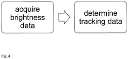
- Figure 4 shows the basic method-steps which are performed in the context of the invention.
- a rather specific approach for tracking at least one medical instrument 1 with respect to an anatomical structure 2 is described without limiting the claimed subject-matter to any specific embodiment.
- a three-dimensional scan of the patient's body/anatomical structure is performed, for obtaining a three-dimensional image dataset.
- the microscope 8 is positioned such that the microscope-integrated camera 4 can observe the medical workspace containing the anatomical structure 2 and the instrument 1.
- the microscope zoom may then be set to a minimum so that it can observe the patient's head during the following registration procedure.
- the second video camera 5 is adjusted to observe the corresponding tracking marker(s) 6, 7.
- a landmark registration may be performed by palpating a plurality of landmarks with a tracked pointer tool 1.
- Each of the landmarks is palpated with the pointer 1 and, as pointer 1 can be seen in the microscope video image, computer 3 connected to both cameras 4 and 5 is able to calculate the spatial position of each of the landmarks with respect to the microscope.
- the relative position of the microscope and a patient-invariant coordinate system can be calculated from the video image of camera 5, the spatial position of each of the landmarks can be transformed into a patient-invariant coordinate system.
- the registration procedure ultimately provides the necessary transformation between the patient-invariant coordinate system and a coordinate system assigned to the image dataset.
- the patient is prepared for a treatment procedure.
- the microscope may be removed from the patient and may be draped with a sterile drape.
- the second video camera 5 may be removed for draping or be replaced by a sterile camera, which may have a sterile housing or which may be provided as disposable article. Further, the patient is draped, as well.
- the microscope 8 is then positioned next to the anatomical structure 2 again and its spatial position with respect to the anatomical structure can be determined. Based on the data describing the relative position between the microscope and the patient-invariant coordinate system, and the data regarding the microscope's zoom and focus, the field of view of the microscope image can be calculated with respect to the patient-invariant coordinate system. Based on the registration data which describes the transformation between an image-invariant coordinate system and a patient-invariant coordinate system, the spatial position of the instrument 1 which is tracked by the microscope-integrated camera 4 can be determined with respect to the actual anatomical structure 2.
Landscapes
- Health & Medical Sciences (AREA)
- Engineering & Computer Science (AREA)
- Life Sciences & Earth Sciences (AREA)
- Surgery (AREA)
- Medical Informatics (AREA)
- General Health & Medical Sciences (AREA)
- Nuclear Medicine, Radiotherapy & Molecular Imaging (AREA)
- Veterinary Medicine (AREA)
- Public Health (AREA)
- Animal Behavior & Ethology (AREA)
- Biomedical Technology (AREA)
- Heart & Thoracic Surgery (AREA)
- Molecular Biology (AREA)
- Computer Vision & Pattern Recognition (AREA)
- Physics & Mathematics (AREA)
- Theoretical Computer Science (AREA)
- General Physics & Mathematics (AREA)
- Robotics (AREA)
- Pathology (AREA)
- Oral & Maxillofacial Surgery (AREA)
- Multimedia (AREA)
- Image Analysis (AREA)
- Image Processing (AREA)
- Length Measuring Devices By Optical Means (AREA)
- Measuring And Recording Apparatus For Diagnosis (AREA)
- Investigating Or Analysing Materials By Optical Means (AREA)
Claims (11)
- Système pour suivre une position spatiale d'au moins un instrument médical (1) à l'intérieur d'un espace de travail médical incluant une structure anatomique (2) d'un patient, le système comprenant un ordinateur (3) ayant un processeur adapté pour réaliser les étapes de :- l'acquisition, dans le processeur, de données de position d'instrument décrivant une position spatiale de l'au moins un instrument médical (1) par rapport à une première caméra (4), en utilisant la première caméra (4) qui est ciblée sur l'espace de travail médical, incluant l'au moins un instrument médical (1)- l'acquisition, dans le processeur, de données de position de caméra décrivant une position spatiale de la première caméra (4) par rapport à la structure anatomique (2), en utilisant une seconde caméra (5) et au moins un marqueur de suivi optique (6, 7) adapté pour être reconnu par la seconde caméra (5), caractérisé en ce quea) la seconde caméra (5) est couplée de façon rigide à la première caméra (4), et l'au moins un marqueur de suivi optique (6, 7) est adapté pour être couplé de façon rigide à la structure anatomique (2) pour l'acquisition des données de position de caméra ; oub) la seconde caméra (5) est adaptée pour être couplée à la structure anatomique (2) pour l'acquisition des données de position de caméra, et l'au moins un marqueur de suivi optique (6, 7) est couplé de façon rigide à la première caméra (4) ;- la détermination, par le processeur et sur la base des données de position d'instrument et des données de position de caméra, de données de suivi décrivant la position spatiale de l'au moins un instrument médical (1) par rapport à la structure anatomique (2).
- Support non transitoire de stockage lisible par ordinateur stockant un programme d'ordinateur qui, lorsqu'il est exécuté sur un processeur d'un ordinateur (3) ou chargé dans la mémoire d'un ordinateur (3), fait en sorte que l'ordinateur (3) réalise un procédé de suivi médical pour suivre une position spatiale d'au moins un instrument médical (1) à l'intérieur d'un espace de travail médical incluant une structure anatomique (2) d'un patient, le procédé comprenant l'exécution, sur un processeur d'un ordinateur (3), des étapes de :- l'acquisition, dans le processeur, de données de position d'instrument décrivant une position spatiale de l'au moins un instrument médical (1) par rapport à une première caméra (4), en utilisant la première caméra (4) qui est ciblée sur l'espace de travail médical, incluant l'au moins un instrument médical (1) ;- l'acquisition, dans le processeur, de données de position de caméra décrivant une position spatiale de la première caméra (4) par rapport à la structure anatomique (2), en utilisant une seconde caméra (5) et au moins un marqueur de suivi optique (6, 7) adapté pour être reconnu par la seconde caméra (5), caractérisé en ce quea) la seconde caméra (5) est couplée de façon rigide à la première caméra (4), et l'au moins un marqueur de suivi optique (6, 7) est adapté pour être couplé de façon rigide à la structure anatomique (2) pour l'acquisition des données de position de caméra ; oub) la seconde caméra (5) est adaptée pour être couplée à la structure anatomique (2) pour l'acquisition des données de position de caméra, et l'au moins un marqueur de suivi optique (6, 7) est couplé de façon rigide à la première caméra (4) ;- la détermination, par le processeur et sur la base des données de position d'instrument et des données de position de caméra, de données de suivi décrivant la position spatiale de l'au moins un instrument médical (1) par rapport à la structure anatomique (2).
- Support de stockage selon la revendication 2, dans lequel la première caméra (4) est couplée de façon rigide à un microscope médical (8) ciblé sur l'espace de travail médical, dans lequel la première caméra (4) est en particulier une caméra intégrée en microscope.
- Support de stockage selon la revendication 2 ou 3, dans lequel la première caméra (4) est librement mobile relativement à la structure anatomique (2).
- Support de stockage selon l'une quelconque des revendications 2 à 4, dans lequel la seconde caméra (5) est couplée de façon rigide ou mobile à la structure anatomique (2), et dans lequel le marqueur de suivi optique (6) est couplé de façon rigide à la première caméra (4).
- Support de stockage selon la revendication 5, dans lequel l'acquisition de données de position de caméra implique le changement d'une direction de visualisation de la seconde caméra (5) entre l'espace de travail médical et le marqueur de suivi (6), particulièrement dans lequel les orientations des directions de visualisation de la seconde caméra (5) sont connues.
- Support de stockage selon l'une quelconque des revendications 2 à 6, dans lequel le procédé comprend en outre l'étape de :- l'acquisition, dans le processeur, de données de mise en coïncidence décrivant une correspondance spatiale d'un jeu de données d'image pré-acquis de la structure anatomique (2) et de la structure anatomique (2) à l'intérieur de l'espace de travail médical ;dans lequel la détermination des données de suivi est sur la base des données de mise en coïncidence.
- Support de stockage selon les revendications 5 et 7, dans lequel, pour l'acquisition des données de mise en coïncidence, la seconde caméra (5) est ciblée sur l'espace de travail médical.
- Support de stockage selon l'une quelconque des revendications 2 à 8, dans lequel au moins un marqueur de suivi (6, 7) comprend un motif optique bidimensionnel, particulièrement un motif optique dépendant de l'orientation.
- Support de stockage selon l'une quelconque des revendications 7 à 9, dans lequel l'acquisition de données de mise en coïncidence implique au moins une procédure de mise en coïncidence sélectionnée à partir de la liste de :- une mise en coïncidence de repère en utilisant un instrument pointeur suivi (1)- une mise en coïncidence de repère impliquant la focalisation du microscope médical (8) sur au moins un repère prédéfini de la structure anatomique (2) ;- une mise en coïncidence vidéo en utilisant le microscope médical (8) ou une seconde caméra vidéo ;- le balayage de la surface de la structure anatomique (2) en utilisant un dispositif de balayage de surface.
- Ordinateur comprenant le support de stockage non transitoire de programme lisible par ordinateur selon la revendication 2.
Priority Applications (1)
| Application Number | Priority Date | Filing Date | Title |
|---|---|---|---|
| EP20180250.1A EP3735929B1 (fr) | 2016-03-17 | 2017-03-09 | Suivi optique |
Applications Claiming Priority (2)
| Application Number | Priority Date | Filing Date | Title |
|---|---|---|---|
| EP2016055816 | 2016-03-17 | ||
| PCT/EP2017/055584 WO2017157763A1 (fr) | 2016-03-17 | 2017-03-09 | Procédé et système de suivi optique |
Related Child Applications (2)
| Application Number | Title | Priority Date | Filing Date |
|---|---|---|---|
| EP20180250.1A Division EP3735929B1 (fr) | 2016-03-17 | 2017-03-09 | Suivi optique |
| EP20180250.1A Division-Into EP3735929B1 (fr) | 2016-03-17 | 2017-03-09 | Suivi optique |
Publications (2)
| Publication Number | Publication Date |
|---|---|
| EP3429498A1 EP3429498A1 (fr) | 2019-01-23 |
| EP3429498B1 true EP3429498B1 (fr) | 2020-08-05 |
Family
ID=58265970
Family Applications (2)
| Application Number | Title | Priority Date | Filing Date |
|---|---|---|---|
| EP20180250.1A Active EP3735929B1 (fr) | 2016-03-17 | 2017-03-09 | Suivi optique |
| EP17709962.9A Active EP3429498B1 (fr) | 2016-03-17 | 2017-03-09 | Système de suivi optique |
Family Applications Before (1)
| Application Number | Title | Priority Date | Filing Date |
|---|---|---|---|
| EP20180250.1A Active EP3735929B1 (fr) | 2016-03-17 | 2017-03-09 | Suivi optique |
Country Status (4)
| Country | Link |
|---|---|
| US (1) | US11062465B2 (fr) |
| EP (2) | EP3735929B1 (fr) |
| CA (2) | CA3112726C (fr) |
| WO (1) | WO2017157763A1 (fr) |
Cited By (2)
| Publication number | Priority date | Publication date | Assignee | Title |
|---|---|---|---|---|
| WO2022072835A1 (fr) | 2020-10-01 | 2022-04-07 | True Digital Surgery | Microscope chirurgical numérique à auto-navigation |
| EP4401663A4 (fr) * | 2021-09-13 | 2025-10-08 | Digital Surgery Systems Inc | Système intégré de navigation et de visualisation chirurgicales, et méthodes associées |
Families Citing this family (18)
| Publication number | Priority date | Publication date | Assignee | Title |
|---|---|---|---|---|
| DE102018206406C5 (de) | 2018-04-25 | 2025-05-15 | Carl Zeiss Meditec Ag | Mikroskopiesystem |
| CN110569006B (zh) * | 2018-06-05 | 2023-12-19 | 广东虚拟现实科技有限公司 | 显示方法、装置、终端设备及存储介质 |
| US11690680B2 (en) | 2019-03-19 | 2023-07-04 | Mako Surgical Corp. | Trackable protective packaging for tools and methods for calibrating tool installation using the same |
| CN114007514A (zh) * | 2019-06-24 | 2022-02-01 | Dm1有限责任公司 | 用于器械投影和跟踪的光学系统和设备 |
| US20210128249A1 (en) * | 2019-10-30 | 2021-05-06 | Medtech Sa | Tracker device for computer-assisted surgery |
| JP7617115B2 (ja) | 2020-01-13 | 2025-01-17 | ストライカー・コーポレイション | ナビゲーション支援手術中にオフセットをモニタするシステム及び方法 |
| CN112075994B (zh) * | 2020-04-13 | 2021-08-31 | 上海复拓知达医疗科技有限公司 | 用于定位医疗器械的光学标识物和医疗器械组件 |
| US20230149096A1 (en) * | 2020-04-22 | 2023-05-18 | 7D Surgical Ulc | Surface detection device with integrated reference feature and methods of use thereof |
| US12171500B2 (en) * | 2020-06-04 | 2024-12-24 | Baxter Medical Systems Gmbh & Co. Kg | Locating system for medical devices |
| EP4164518A4 (fr) * | 2020-06-11 | 2024-06-26 | Monogram Orthopaedics Inc. | Procédés et systèmes de navigation et/ou de suivi robotique |
| DE102020118801A1 (de) | 2020-07-16 | 2022-01-20 | Carl Zeiss Microscopy Gmbh | Mikroskop und verfahren zur abstandsbestimmung einer probenreferenzebene |
| CA3190464A1 (fr) * | 2020-08-10 | 2022-02-17 | Brainlab Ag | Etalonnage de camera de microscope |
| WO2022133049A1 (fr) * | 2020-12-18 | 2022-06-23 | University Of Florida Research Foundation, Incorporated | Systèmes et procédés de recalage d'une représentation 3d d'un patient avec un dispositif médical pour l'alignement du patient |
| DE102021206971A1 (de) * | 2021-07-02 | 2023-01-05 | Carl Zeiss Meditec Ag | Verfahren und System zur optischen Lageerfassung zumindest eines Instruments in einem Operationssaal |
| DE102021207950A1 (de) | 2021-07-23 | 2023-01-26 | Carl Zeiss Meditec Ag | Verfahren und System zur Bestimmung einer Lage zumindest eines Objekts in einem Operationssaal |
| DE102021128478A1 (de) * | 2021-11-02 | 2023-05-04 | B. Braun New Ventures GmbH | Chirurgisches Navigationssystem mit verbessertem Instrumententracking und Navigationsverfahren |
| EP4193956A1 (fr) * | 2021-12-10 | 2023-06-14 | Koninklijke Philips N.V. | Marqueurs de poursuite optique |
| US20250359943A1 (en) * | 2024-05-21 | 2025-11-27 | Fujifilm Corporation | Medical instrument, medical support device, and medical support program |
Family Cites Families (17)
| Publication number | Priority date | Publication date | Assignee | Title |
|---|---|---|---|---|
| US6384908B1 (en) | 1996-08-15 | 2002-05-07 | Go Sensors, Llc | Orientation dependent radiation source |
| EP1415609A1 (fr) * | 1998-01-28 | 2004-05-06 | Sherwood Services AG | Système de suivi d'un objet optique |
| US6671058B1 (en) | 1998-03-23 | 2003-12-30 | Leica Geosystems Ag | Method for determining the position and rotational position of an object |
| JP4101951B2 (ja) | 1998-11-10 | 2008-06-18 | オリンパス株式会社 | 手術用顕微鏡 |
| GB0204549D0 (en) * | 2002-02-27 | 2002-04-10 | Depuy Int Ltd | A surgical instrument system |
| WO2003105709A1 (fr) | 2002-06-13 | 2003-12-24 | Möller-Wedel GmbH | Procede et instrument de navigation chirurgicale |
| KR101270912B1 (ko) | 2005-06-09 | 2013-06-03 | 이에프에 인더스트릴레 포르슝 운트 엔트빅룽 게엠베하 | 물체의 공간적 위치 및 방향의 비접촉식 결정 및 측정 장치및 방법과, 의료용 툴을 교정 및 확인하기 위한 방법,그리고 의료용 툴 상의 패턴이나 구조물 |
| US9289267B2 (en) * | 2005-06-14 | 2016-03-22 | Siemens Medical Solutions Usa, Inc. | Method and apparatus for minimally invasive surgery using endoscopes |
| EP1952779B1 (fr) * | 2007-02-01 | 2012-04-04 | BrainLAB AG | Méthode et système d'identification des instruments médicaux |
| US8059267B2 (en) | 2008-08-25 | 2011-11-15 | Go Sensors, Llc | Orientation dependent radiation source and methods |
| US8625107B2 (en) | 2010-05-19 | 2014-01-07 | Uwm Research Foundation, Inc. | Target for motion tracking system |
| US8657809B2 (en) | 2010-09-29 | 2014-02-25 | Stryker Leibinger Gmbh & Co., Kg | Surgical navigation system |
| EP2769689B8 (fr) | 2013-02-25 | 2018-06-27 | Stryker European Holdings I, LLC | Technique informatique pour calculer la position d'un dispositif chirurgical |
| WO2015024600A1 (fr) | 2013-08-23 | 2015-02-26 | Stryker Leibinger Gmbh & Co. Kg | Technique informatique de détermination d'une transformation de coordonnées pour navigation chirurgicale |
| US8880151B1 (en) | 2013-11-27 | 2014-11-04 | Clear Guide Medical, Llc | Surgical needle for a surgical system with optical recognition |
| DE102014102425B4 (de) | 2014-02-25 | 2018-06-28 | Carl Zeiss Meditec Ag | Mikroskopsystem und Mikroskopieverfahren unter Verwendung digitaler Marker |
| US10070940B2 (en) * | 2014-09-15 | 2018-09-11 | Synaptive Medical (Barbados) Inc. | End effector for a positioning device |
-
2017
- 2017-03-09 CA CA3112726A patent/CA3112726C/fr active Active
- 2017-03-09 WO PCT/EP2017/055584 patent/WO2017157763A1/fr not_active Ceased
- 2017-03-09 EP EP20180250.1A patent/EP3735929B1/fr active Active
- 2017-03-09 EP EP17709962.9A patent/EP3429498B1/fr active Active
- 2017-03-09 CA CA3005502A patent/CA3005502C/fr active Active
- 2017-03-09 US US16/083,928 patent/US11062465B2/en active Active
Non-Patent Citations (1)
| Title |
|---|
| None * |
Cited By (3)
| Publication number | Priority date | Publication date | Assignee | Title |
|---|---|---|---|---|
| WO2022072835A1 (fr) | 2020-10-01 | 2022-04-07 | True Digital Surgery | Microscope chirurgical numérique à auto-navigation |
| EP4221581A4 (fr) * | 2020-10-01 | 2024-10-30 | True Digital Surgery | Microscope chirurgical numérique à auto-navigation |
| EP4401663A4 (fr) * | 2021-09-13 | 2025-10-08 | Digital Surgery Systems Inc | Système intégré de navigation et de visualisation chirurgicales, et méthodes associées |
Also Published As
| Publication number | Publication date |
|---|---|
| CA3005502C (fr) | 2021-03-30 |
| EP3429498A1 (fr) | 2019-01-23 |
| CA3005502A1 (fr) | 2017-09-21 |
| US20200193622A1 (en) | 2020-06-18 |
| WO2017157763A1 (fr) | 2017-09-21 |
| CA3112726A1 (fr) | 2017-09-21 |
| EP3735929A1 (fr) | 2020-11-11 |
| US11062465B2 (en) | 2021-07-13 |
| CA3112726C (fr) | 2024-10-08 |
| EP3735929B1 (fr) | 2024-06-19 |
Similar Documents
| Publication | Publication Date | Title |
|---|---|---|
| EP3429498B1 (fr) | Système de suivi optique | |
| EP3664737B1 (fr) | Enregistrement et suivi de patient basé sur vidéo | |
| US11963723B2 (en) | Visualization of medical data depending on viewing-characteristics | |
| US12262959B2 (en) | Method for determining the spatial position of objects | |
| EP3413773B1 (fr) | Détermination de vue en ligne | |
| US20220354590A1 (en) | Method for registering articulated anatomical structures | |
| US12406396B2 (en) | Microscope camera calibration | |
| EP4415647B1 (fr) | Conjonction des visualisations 2d et 3d dans la réalité augmentée | |
| EP4401639B1 (fr) | Sonde ultrasonore segmentée | |
| EP4196035B1 (fr) | Détermination d'une zone d'évitement pour un dispositif de référence | |
| WO2025124884A1 (fr) | Système de serrage de tête | |
| WO2026046516A1 (fr) | Procédé médical mis en œuvre par ordinateur pour guider l'utilisateur dans l'enregistrement de patient | |
| WO2025067673A1 (fr) | Vue en réalité mixte |
Legal Events
| Date | Code | Title | Description |
|---|---|---|---|
| STAA | Information on the status of an ep patent application or granted ep patent |
Free format text: STATUS: UNKNOWN |
|
| STAA | Information on the status of an ep patent application or granted ep patent |
Free format text: STATUS: THE INTERNATIONAL PUBLICATION HAS BEEN MADE |
|
| PUAI | Public reference made under article 153(3) epc to a published international application that has entered the european phase |
Free format text: ORIGINAL CODE: 0009012 |
|
| STAA | Information on the status of an ep patent application or granted ep patent |
Free format text: STATUS: REQUEST FOR EXAMINATION WAS MADE |
|
| 17P | Request for examination filed |
Effective date: 20180508 |
|
| AK | Designated contracting states |
Kind code of ref document: A1 Designated state(s): AL AT BE BG CH CY CZ DE DK EE ES FI FR GB GR HR HU IE IS IT LI LT LU LV MC MK MT NL NO PL PT RO RS SE SI SK SM TR |
|
| AX | Request for extension of the european patent |
Extension state: BA ME |
|
| DAV | Request for validation of the european patent (deleted) | ||
| DAX | Request for extension of the european patent (deleted) | ||
| STAA | Information on the status of an ep patent application or granted ep patent |
Free format text: STATUS: EXAMINATION IS IN PROGRESS |
|
| 17Q | First examination report despatched |
Effective date: 20190919 |
|
| GRAP | Despatch of communication of intention to grant a patent |
Free format text: ORIGINAL CODE: EPIDOSNIGR1 |
|
| STAA | Information on the status of an ep patent application or granted ep patent |
Free format text: STATUS: GRANT OF PATENT IS INTENDED |
|
| INTG | Intention to grant announced |
Effective date: 20200319 |
|
| GRAS | Grant fee paid |
Free format text: ORIGINAL CODE: EPIDOSNIGR3 |
|
| GRAA | (expected) grant |
Free format text: ORIGINAL CODE: 0009210 |
|
| STAA | Information on the status of an ep patent application or granted ep patent |
Free format text: STATUS: THE PATENT HAS BEEN GRANTED |
|
| AK | Designated contracting states |
Kind code of ref document: B1 Designated state(s): AL AT BE BG CH CY CZ DE DK EE ES FI FR GB GR HR HU IE IS IT LI LT LU LV MC MK MT NL NO PL PT RO RS SE SI SK SM TR |
|
| REG | Reference to a national code |
Ref country code: GB Ref legal event code: FG4D |
|
| REG | Reference to a national code |
Ref country code: CH Ref legal event code: EP |
|
| REG | Reference to a national code |
Ref country code: AT Ref legal event code: REF Ref document number: 1297634 Country of ref document: AT Kind code of ref document: T Effective date: 20200815 |
|
| REG | Reference to a national code |
Ref country code: DE Ref legal event code: R096 Ref document number: 602017021013 Country of ref document: DE |
|
| REG | Reference to a national code |
Ref country code: IE Ref legal event code: FG4D |
|
| REG | Reference to a national code |
Ref country code: LT Ref legal event code: MG4D |
|
| REG | Reference to a national code |
Ref country code: NL Ref legal event code: MP Effective date: 20200805 |
|
| REG | Reference to a national code |
Ref country code: AT Ref legal event code: MK05 Ref document number: 1297634 Country of ref document: AT Kind code of ref document: T Effective date: 20200805 |
|
| PG25 | Lapsed in a contracting state [announced via postgrant information from national office to epo] |
Ref country code: SE Free format text: LAPSE BECAUSE OF FAILURE TO SUBMIT A TRANSLATION OF THE DESCRIPTION OR TO PAY THE FEE WITHIN THE PRESCRIBED TIME-LIMIT Effective date: 20200805 Ref country code: AT Free format text: LAPSE BECAUSE OF FAILURE TO SUBMIT A TRANSLATION OF THE DESCRIPTION OR TO PAY THE FEE WITHIN THE PRESCRIBED TIME-LIMIT Effective date: 20200805 Ref country code: HR Free format text: LAPSE BECAUSE OF FAILURE TO SUBMIT A TRANSLATION OF THE DESCRIPTION OR TO PAY THE FEE WITHIN THE PRESCRIBED TIME-LIMIT Effective date: 20200805 Ref country code: FI Free format text: LAPSE BECAUSE OF FAILURE TO SUBMIT A TRANSLATION OF THE DESCRIPTION OR TO PAY THE FEE WITHIN THE PRESCRIBED TIME-LIMIT Effective date: 20200805 Ref country code: GR Free format text: LAPSE BECAUSE OF FAILURE TO SUBMIT A TRANSLATION OF THE DESCRIPTION OR TO PAY THE FEE WITHIN THE PRESCRIBED TIME-LIMIT Effective date: 20201106 Ref country code: NO Free format text: LAPSE BECAUSE OF FAILURE TO SUBMIT A TRANSLATION OF THE DESCRIPTION OR TO PAY THE FEE WITHIN THE PRESCRIBED TIME-LIMIT Effective date: 20201105 Ref country code: PT Free format text: LAPSE BECAUSE OF FAILURE TO SUBMIT A TRANSLATION OF THE DESCRIPTION OR TO PAY THE FEE WITHIN THE PRESCRIBED TIME-LIMIT Effective date: 20201207 Ref country code: ES Free format text: LAPSE BECAUSE OF FAILURE TO SUBMIT A TRANSLATION OF THE DESCRIPTION OR TO PAY THE FEE WITHIN THE PRESCRIBED TIME-LIMIT Effective date: 20200805 Ref country code: BG Free format text: LAPSE BECAUSE OF FAILURE TO SUBMIT A TRANSLATION OF THE DESCRIPTION OR TO PAY THE FEE WITHIN THE PRESCRIBED TIME-LIMIT Effective date: 20201105 Ref country code: LT Free format text: LAPSE BECAUSE OF FAILURE TO SUBMIT A TRANSLATION OF THE DESCRIPTION OR TO PAY THE FEE WITHIN THE PRESCRIBED TIME-LIMIT Effective date: 20200805 |
|
| PG25 | Lapsed in a contracting state [announced via postgrant information from national office to epo] |
Ref country code: NL Free format text: LAPSE BECAUSE OF FAILURE TO SUBMIT A TRANSLATION OF THE DESCRIPTION OR TO PAY THE FEE WITHIN THE PRESCRIBED TIME-LIMIT Effective date: 20200805 Ref country code: LV Free format text: LAPSE BECAUSE OF FAILURE TO SUBMIT A TRANSLATION OF THE DESCRIPTION OR TO PAY THE FEE WITHIN THE PRESCRIBED TIME-LIMIT Effective date: 20200805 Ref country code: PL Free format text: LAPSE BECAUSE OF FAILURE TO SUBMIT A TRANSLATION OF THE DESCRIPTION OR TO PAY THE FEE WITHIN THE PRESCRIBED TIME-LIMIT Effective date: 20200805 Ref country code: RS Free format text: LAPSE BECAUSE OF FAILURE TO SUBMIT A TRANSLATION OF THE DESCRIPTION OR TO PAY THE FEE WITHIN THE PRESCRIBED TIME-LIMIT Effective date: 20200805 Ref country code: IS Free format text: LAPSE BECAUSE OF FAILURE TO SUBMIT A TRANSLATION OF THE DESCRIPTION OR TO PAY THE FEE WITHIN THE PRESCRIBED TIME-LIMIT Effective date: 20201205 |
|
| PG25 | Lapsed in a contracting state [announced via postgrant information from national office to epo] |
Ref country code: EE Free format text: LAPSE BECAUSE OF FAILURE TO SUBMIT A TRANSLATION OF THE DESCRIPTION OR TO PAY THE FEE WITHIN THE PRESCRIBED TIME-LIMIT Effective date: 20200805 Ref country code: SM Free format text: LAPSE BECAUSE OF FAILURE TO SUBMIT A TRANSLATION OF THE DESCRIPTION OR TO PAY THE FEE WITHIN THE PRESCRIBED TIME-LIMIT Effective date: 20200805 Ref country code: RO Free format text: LAPSE BECAUSE OF FAILURE TO SUBMIT A TRANSLATION OF THE DESCRIPTION OR TO PAY THE FEE WITHIN THE PRESCRIBED TIME-LIMIT Effective date: 20200805 Ref country code: CZ Free format text: LAPSE BECAUSE OF FAILURE TO SUBMIT A TRANSLATION OF THE DESCRIPTION OR TO PAY THE FEE WITHIN THE PRESCRIBED TIME-LIMIT Effective date: 20200805 Ref country code: DK Free format text: LAPSE BECAUSE OF FAILURE TO SUBMIT A TRANSLATION OF THE DESCRIPTION OR TO PAY THE FEE WITHIN THE PRESCRIBED TIME-LIMIT Effective date: 20200805 |
|
| REG | Reference to a national code |
Ref country code: DE Ref legal event code: R097 Ref document number: 602017021013 Country of ref document: DE |
|
| PG25 | Lapsed in a contracting state [announced via postgrant information from national office to epo] |
Ref country code: AL Free format text: LAPSE BECAUSE OF FAILURE TO SUBMIT A TRANSLATION OF THE DESCRIPTION OR TO PAY THE FEE WITHIN THE PRESCRIBED TIME-LIMIT Effective date: 20200805 |
|
| PLBE | No opposition filed within time limit |
Free format text: ORIGINAL CODE: 0009261 |
|
| STAA | Information on the status of an ep patent application or granted ep patent |
Free format text: STATUS: NO OPPOSITION FILED WITHIN TIME LIMIT |
|
| PG25 | Lapsed in a contracting state [announced via postgrant information from national office to epo] |
Ref country code: SK Free format text: LAPSE BECAUSE OF FAILURE TO SUBMIT A TRANSLATION OF THE DESCRIPTION OR TO PAY THE FEE WITHIN THE PRESCRIBED TIME-LIMIT Effective date: 20200805 |
|
| 26N | No opposition filed |
Effective date: 20210507 |
|
| PG25 | Lapsed in a contracting state [announced via postgrant information from national office to epo] |
Ref country code: IT Free format text: LAPSE BECAUSE OF FAILURE TO SUBMIT A TRANSLATION OF THE DESCRIPTION OR TO PAY THE FEE WITHIN THE PRESCRIBED TIME-LIMIT Effective date: 20200805 |
|
| PG25 | Lapsed in a contracting state [announced via postgrant information from national office to epo] |
Ref country code: SI Free format text: LAPSE BECAUSE OF FAILURE TO SUBMIT A TRANSLATION OF THE DESCRIPTION OR TO PAY THE FEE WITHIN THE PRESCRIBED TIME-LIMIT Effective date: 20200805 |
|
| PG25 | Lapsed in a contracting state [announced via postgrant information from national office to epo] |
Ref country code: MC Free format text: LAPSE BECAUSE OF FAILURE TO SUBMIT A TRANSLATION OF THE DESCRIPTION OR TO PAY THE FEE WITHIN THE PRESCRIBED TIME-LIMIT Effective date: 20200805 |
|
| REG | Reference to a national code |
Ref country code: CH Ref legal event code: PL |
|
| REG | Reference to a national code |
Ref country code: BE Ref legal event code: MM Effective date: 20210331 |
|
| PG25 | Lapsed in a contracting state [announced via postgrant information from national office to epo] |
Ref country code: CH Free format text: LAPSE BECAUSE OF NON-PAYMENT OF DUE FEES Effective date: 20210331 Ref country code: LI Free format text: LAPSE BECAUSE OF NON-PAYMENT OF DUE FEES Effective date: 20210331 Ref country code: LU Free format text: LAPSE BECAUSE OF NON-PAYMENT OF DUE FEES Effective date: 20210309 Ref country code: IE Free format text: LAPSE BECAUSE OF NON-PAYMENT OF DUE FEES Effective date: 20210309 Ref country code: FR Free format text: LAPSE BECAUSE OF NON-PAYMENT OF DUE FEES Effective date: 20210331 |
|
| PG25 | Lapsed in a contracting state [announced via postgrant information from national office to epo] |
Ref country code: BE Free format text: LAPSE BECAUSE OF NON-PAYMENT OF DUE FEES Effective date: 20210331 |
|
| P01 | Opt-out of the competence of the unified patent court (upc) registered |
Effective date: 20230512 |
|
| PG25 | Lapsed in a contracting state [announced via postgrant information from national office to epo] |
Ref country code: CY Free format text: LAPSE BECAUSE OF FAILURE TO SUBMIT A TRANSLATION OF THE DESCRIPTION OR TO PAY THE FEE WITHIN THE PRESCRIBED TIME-LIMIT Effective date: 20200805 |
|
| PG25 | Lapsed in a contracting state [announced via postgrant information from national office to epo] |
Ref country code: HU Free format text: LAPSE BECAUSE OF FAILURE TO SUBMIT A TRANSLATION OF THE DESCRIPTION OR TO PAY THE FEE WITHIN THE PRESCRIBED TIME-LIMIT; INVALID AB INITIO Effective date: 20170309 |
|
| PG25 | Lapsed in a contracting state [announced via postgrant information from national office to epo] |
Ref country code: MK Free format text: LAPSE BECAUSE OF FAILURE TO SUBMIT A TRANSLATION OF THE DESCRIPTION OR TO PAY THE FEE WITHIN THE PRESCRIBED TIME-LIMIT Effective date: 20200805 |
|
| PG25 | Lapsed in a contracting state [announced via postgrant information from national office to epo] |
Ref country code: MT Free format text: LAPSE BECAUSE OF FAILURE TO SUBMIT A TRANSLATION OF THE DESCRIPTION OR TO PAY THE FEE WITHIN THE PRESCRIBED TIME-LIMIT Effective date: 20200805 |
|
| REG | Reference to a national code |
Ref country code: DE Ref legal event code: R081 Ref document number: 602017021013 Country of ref document: DE Owner name: BRAINLAB SE, DE Free format text: FORMER OWNER: BRAINLAB AG, 81829 MUENCHEN, DE |
|
| PG25 | Lapsed in a contracting state [announced via postgrant information from national office to epo] |
Ref country code: TR Free format text: LAPSE BECAUSE OF FAILURE TO SUBMIT A TRANSLATION OF THE DESCRIPTION OR TO PAY THE FEE WITHIN THE PRESCRIBED TIME-LIMIT Effective date: 20200805 |
|
| PGFP | Annual fee paid to national office [announced via postgrant information from national office to epo] |
Ref country code: GB Payment date: 20260324 Year of fee payment: 10 |
|
| PGFP | Annual fee paid to national office [announced via postgrant information from national office to epo] |
Ref country code: DE Payment date: 20260319 Year of fee payment: 10 |