EP3429754B1 - Cartouches de préparation d'échantillons - Google Patents
Cartouches de préparation d'échantillons Download PDFInfo
- Publication number
- EP3429754B1 EP3429754B1 EP17767484.3A EP17767484A EP3429754B1 EP 3429754 B1 EP3429754 B1 EP 3429754B1 EP 17767484 A EP17767484 A EP 17767484A EP 3429754 B1 EP3429754 B1 EP 3429754B1
- Authority
- EP
- European Patent Office
- Prior art keywords
- plunger
- wells
- opening
- cartridge
- frame
- Prior art date
- Legal status (The legal status is an assumption and is not a legal conclusion. Google has not performed a legal analysis and makes no representation as to the accuracy of the status listed.)
- Active
Links
Images




Classifications
-
- C—CHEMISTRY; METALLURGY
- C12—BIOCHEMISTRY; BEER; SPIRITS; WINE; VINEGAR; MICROBIOLOGY; ENZYMOLOGY; MUTATION OR GENETIC ENGINEERING
- C12Q—MEASURING OR TESTING PROCESSES INVOLVING ENZYMES, NUCLEIC ACIDS OR MICROORGANISMS; COMPOSITIONS OR TEST PAPERS THEREFOR; PROCESSES OF PREPARING SUCH COMPOSITIONS; CONDITION-RESPONSIVE CONTROL IN MICROBIOLOGICAL OR ENZYMOLOGICAL PROCESSES
- C12Q1/00—Measuring or testing processes involving enzymes, nucleic acids or microorganisms; Compositions therefor; Processes of preparing such compositions
- C12Q1/68—Measuring or testing processes involving enzymes, nucleic acids or microorganisms; Compositions therefor; Processes of preparing such compositions involving nucleic acids
- C12Q1/6806—Preparing nucleic acids for analysis, e.g. for polymerase chain reaction [PCR] assay
-
- B—PERFORMING OPERATIONS; TRANSPORTING
- B01—PHYSICAL OR CHEMICAL PROCESSES OR APPARATUS IN GENERAL
- B01L—CHEMICAL OR PHYSICAL LABORATORY APPARATUS FOR GENERAL USE
- B01L3/00—Containers or dishes for laboratory use, e.g. laboratory glassware; Droppers
- B01L3/50—Containers for the purpose of retaining a material to be analysed, e.g. test tubes
- B01L3/508—Rigid containers without fluid transport within
- B01L3/5085—Rigid containers without fluid transport within for multiple samples, e.g. microtitration plates
- B01L3/50851—Rigid containers without fluid transport within for multiple samples, e.g. microtitration plates specially adapted for heating or cooling samples
-
- B—PERFORMING OPERATIONS; TRANSPORTING
- B01—PHYSICAL OR CHEMICAL PROCESSES OR APPARATUS IN GENERAL
- B01L—CHEMICAL OR PHYSICAL LABORATORY APPARATUS FOR GENERAL USE
- B01L3/00—Containers or dishes for laboratory use, e.g. laboratory glassware; Droppers
- B01L3/50—Containers for the purpose of retaining a material to be analysed, e.g. test tubes
- B01L3/508—Rigid containers without fluid transport within
- B01L3/5085—Rigid containers without fluid transport within for multiple samples, e.g. microtitration plates
- B01L3/50853—Rigid containers without fluid transport within for multiple samples, e.g. microtitration plates with covers or lids
-
- B—PERFORMING OPERATIONS; TRANSPORTING
- B01—PHYSICAL OR CHEMICAL PROCESSES OR APPARATUS IN GENERAL
- B01L—CHEMICAL OR PHYSICAL LABORATORY APPARATUS FOR GENERAL USE
- B01L7/00—Heating or cooling apparatus; Heat insulating devices
- B01L7/52—Heating or cooling apparatus; Heat insulating devices with provision for submitting samples to a predetermined sequence of different temperatures, e.g. for treating nucleic acid samples
-
- B—PERFORMING OPERATIONS; TRANSPORTING
- B01—PHYSICAL OR CHEMICAL PROCESSES OR APPARATUS IN GENERAL
- B01L—CHEMICAL OR PHYSICAL LABORATORY APPARATUS FOR GENERAL USE
- B01L7/00—Heating or cooling apparatus; Heat insulating devices
- B01L7/52—Heating or cooling apparatus; Heat insulating devices with provision for submitting samples to a predetermined sequence of different temperatures, e.g. for treating nucleic acid samples
- B01L7/525—Heating or cooling apparatus; Heat insulating devices with provision for submitting samples to a predetermined sequence of different temperatures, e.g. for treating nucleic acid samples with physical movement of samples between temperature zones
-
- C—CHEMISTRY; METALLURGY
- C12—BIOCHEMISTRY; BEER; SPIRITS; WINE; VINEGAR; MICROBIOLOGY; ENZYMOLOGY; MUTATION OR GENETIC ENGINEERING
- C12N—MICROORGANISMS OR ENZYMES; COMPOSITIONS THEREOF; PROPAGATING, PRESERVING, OR MAINTAINING MICROORGANISMS; MUTATION OR GENETIC ENGINEERING; CULTURE MEDIA
- C12N15/00—Mutation or genetic engineering; DNA or RNA concerning genetic engineering, vectors, e.g. plasmids, or their isolation, preparation or purification; Use of hosts therefor
- C12N15/09—Recombinant DNA-technology
- C12N15/10—Processes for the isolation, preparation or purification of DNA or RNA
- C12N15/1003—Extracting or separating nucleic acids from biological samples, e.g. pure separation or isolation methods; Conditions, buffers or apparatuses therefor
- C12N15/1006—Extracting or separating nucleic acids from biological samples, e.g. pure separation or isolation methods; Conditions, buffers or apparatuses therefor by means of a solid support carrier, e.g. particles, polymers
- C12N15/1013—Extracting or separating nucleic acids from biological samples, e.g. pure separation or isolation methods; Conditions, buffers or apparatuses therefor by means of a solid support carrier, e.g. particles, polymers by using magnetic beads
-
- B—PERFORMING OPERATIONS; TRANSPORTING
- B01—PHYSICAL OR CHEMICAL PROCESSES OR APPARATUS IN GENERAL
- B01L—CHEMICAL OR PHYSICAL LABORATORY APPARATUS FOR GENERAL USE
- B01L2200/00—Solutions for specific problems relating to chemical or physical laboratory apparatus
- B01L2200/10—Integrating sample preparation and analysis in single entity, e.g. lab-on-a-chip concept
-
- B—PERFORMING OPERATIONS; TRANSPORTING
- B01—PHYSICAL OR CHEMICAL PROCESSES OR APPARATUS IN GENERAL
- B01L—CHEMICAL OR PHYSICAL LABORATORY APPARATUS FOR GENERAL USE
- B01L2300/00—Additional constructional details
- B01L2300/04—Closures and closing means
- B01L2300/041—Connecting closures to device or container
- B01L2300/042—Caps; Plugs
-
- B—PERFORMING OPERATIONS; TRANSPORTING
- B01—PHYSICAL OR CHEMICAL PROCESSES OR APPARATUS IN GENERAL
- B01L—CHEMICAL OR PHYSICAL LABORATORY APPARATUS FOR GENERAL USE
- B01L2300/00—Additional constructional details
- B01L2300/08—Geometry, shape and general structure
- B01L2300/0809—Geometry, shape and general structure rectangular shaped
- B01L2300/0829—Multi-well plates; Microtitration plates
-
- B—PERFORMING OPERATIONS; TRANSPORTING
- B01—PHYSICAL OR CHEMICAL PROCESSES OR APPARATUS IN GENERAL
- B01L—CHEMICAL OR PHYSICAL LABORATORY APPARATUS FOR GENERAL USE
- B01L2300/00—Additional constructional details
- B01L2300/08—Geometry, shape and general structure
- B01L2300/0848—Specific forms of parts of containers
-
- B—PERFORMING OPERATIONS; TRANSPORTING
- B01—PHYSICAL OR CHEMICAL PROCESSES OR APPARATUS IN GENERAL
- B01L—CHEMICAL OR PHYSICAL LABORATORY APPARATUS FOR GENERAL USE
- B01L2300/00—Additional constructional details
- B01L2300/08—Geometry, shape and general structure
- B01L2300/0861—Configuration of multiple channels and/or chambers in a single devices
-
- B—PERFORMING OPERATIONS; TRANSPORTING
- B01—PHYSICAL OR CHEMICAL PROCESSES OR APPARATUS IN GENERAL
- B01L—CHEMICAL OR PHYSICAL LABORATORY APPARATUS FOR GENERAL USE
- B01L2400/00—Moving or stopping fluids
- B01L2400/04—Moving fluids with specific forces or mechanical means
- B01L2400/0475—Moving fluids with specific forces or mechanical means specific mechanical means and fluid pressure
- B01L2400/0478—Moving fluids with specific forces or mechanical means specific mechanical means and fluid pressure pistons
Definitions
- Nucleic acid isolation and purification is a set of molecular biology techniques used for the extraction of DNA and RNA for use in downstream applications. Nucleic acid isolation and purification approaches include column-based isolation and purification, reagent-based isolation and purification, magnetic bead-based isolation and purification, and other technologies. Reagents, kits and instruments that find use in isolating and purifying nucleic acids are available. Poor sample preparation can lead to suboptimal results in downstream applications, and it is for this reason that optimized versions of kits have emerged to address variation in sample source, be it blood, plant tissue, fungi, or bacteria.
- a system that automates steps to perform nucleic acid amplification assays from sample processing through amplification, detection, and data reduction is the Abbott m2000 System.
- This system includes the Abbott m2000sp module which reads and processes bar coded primary sample tubes and processes up to 96 specimens, controls, and calibrators in batch mode.
- the sample preparation process consists of releasing the nucleic acid target from its native biological source (e.g., lysis of cells, such as patient cells or microorganisms) using chaotropic nucleic acid extraction technology, binding of nucleic acids to a solid phase (magnetic particles) using silica or iron oxide nucleic acid chemistry, separation of the solid phase from the residual lysis solution using magnetic separation technology, washing to remove unwanted materials, and elution or separation of nucleic acid from the solid phase using fluid handling technology.
- the operator seals and manually transfers the PCR plate to the Abbott m2000rt module for nucleic acid detection.
- US 2013/130369 A1 discloses systems and methods for processing and analyzing samples.
- the system may process samples, such as biological fluids, using assay cartridges which can be processed at different processing locations.
- the system can be used for PCR processing.
- the different processing locations may include a preparation location where samples can be prepared and an analysis location where samples can be analyzed.
- the system may also include a number of processing stations which may include processing lanes.
- thermal cycler modules and an appropriate optical detection system can be used to detect the presence or absence of certain nucleic acid sequences in the samples.
- the system can be used to accurately and rapidly process samples.
- US 2009/136386 A1 discloses a rack for holding samples and various reagents, wherein the rack may be used for loading the samples and reagents prior to using the reagents.
- the rack accepts complementary reagent holders, each of which contain a set of reagents for carrying out a predetermined processing operation, such as preparing biological samples for amplifying and detecting polynucleotides extracted from the samples.
- sample preparation cartridges including a frame the includes a plurality of wells integrated therewith, where the plurality of wells have a closed bottom and an open top.
- the frame further includes an opening within the frame having a reaction vessel (RV) or RV cap removably disposed therein, where the plurality of wells and the opening are linearly arranged relative to each other.
- sample preparation cartridges that include a frame, two or more cartridge separation projections on a top side of the frame, and two or more cartridge separation projections on a bottom side of the frame. The cartridge separation projections separate the cartridge and a different cartridge when the cartridge and different cartridge are stacked. Methods of using the sample preparation cartridges, as well as nucleic acid sample preparation units that include the sample preparation cartridges, are also provided.
- the sample preparation cartridges include a frame including a plurality of wells integrated therewith, where the plurality of wells have a closed bottom and an open top.
- the frame further includes an opening within the frame having a reaction vessel (RV) or RV cap removably disposed therein.
- RV reaction vessel
- the plurality of wells and the opening are linearly arranged relative to each other.
- a RV is removably disposed in the opening, e.g., an opening that is open at the bottom, or an opening that is closed at the bottom.
- the opening may be a first opening
- the frame may include a second opening in which a RV cap is removably disposed.
- the second opening may be open at the bottom or closed at the bottom.
- the plurality of wells is a first plurality of wells
- the frame includes a second plurality of linearly arranged wells integrated therewith, where the second plurality of wells have a closed bottom and an open top.
- the frame includes an opening within the frame linearly arranged with the second plurality of wells.
- the opening linearly arranged with the second plurality of wells has a RV or RV cap removably disposed therein.
- the frame when the cartridge includes first and second pluralities of linearly arranged wells as described above, the frame further includes a third plurality of linearly arranged wells integrated therewith, where the third plurality of wells have a closed bottom and an open top.
- the frame includes an opening within the frame linearly arranged with the third plurality of wells. The opening linearly arranged with the third plurality of wells has a RV or RV cap removably disposed therein.
- the frame when the cartridge includes first, second and third pluralities of linearly arranged wells as described above, the frame further includes a fourth plurality of linearly arranged wells integrated therewith, where the fourth plurality of wells have a closed bottom and an open top.
- the frame includes an opening within the frame linearly arranged with the fourth plurality of wells. The opening linearly arranged with the fourth plurality of wells has a RV or RV cap removably disposed therein.
- the RV and/or RV cap present in the cartridges of the present disclosure may be any of the RVs or RV caps described in WO 2017/161058 A1 , which claims priority to USSN 62/308,620 .
- a plunger of the instant disclosure may include an elongated hollow clone structure and a top opening.
- the plunger may include a plurality of flutes at the closed end. The distance that the flutes extend to the closed end of the plunger may vary but, in certain embodiments extend into a rounded tip but not to an end nub.
- the flute being a groove in the plunger, defines a cavity which may, in some instances, be collectively defined for all flutes of the plurality as defining an empty volume of space.
- the volume of space ascribed to the flutes may be determined from the difference in volume of the plunger with and without the flutes (that is, the difference between a plunger with the flutes and an identical plunger without the flutes). Such volume may or may not correspond to the volume of buffer used in one or more of the processing methods as describe herein.
- the general shape of the plunger in relationship to the shape of the well, is configured to minimize contact between surfaces of the plunger with surfaces of the well, including but not limited to e.g., one or more tapers of the plunger, the contours of end of the plunger (e.g., contours of the rounded end of the plunger), etc.
- the plunger end and the bottom of an elution well are of sufficiently dissimilar shape so as to minimize contact of surfaces of the plunger with surfaces of the elution well.
- Plungers that find use in the SP cartridges, methods and sample preparation units of the present disclosure include those described, e.g., in WO 2017/160980 A1 , which claims priority to USSN 62/308,645 .
- the opening in which the plunger is removably disposed may be open or closed at the bottom.
- an opening that is open at the bottom finds use in holding an unused plunger.
- an opening that is closed at the bottom finds use in holding a used plunger, e.g., to contain any residual liquid sample preparation reagents present on the plunger upon completion of preparing a sample.
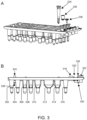
- An example of a plunger is shown in FIG. 3 , Panel A.
- Sample preparation cartridges of the present disclosure may include two or more cartridge separation projections on a top side of the frame and two or more cartridge separation projections on a bottom side of the frame, where the cartridge separation projections separate the cartridge and a different cartridge when the cartridge and different cartridge are stacked.
- a cartridge includes four cartridge separation projections on the top side of the frame and four cartridge separation projections on the bottom side of the frame.
- the top and bottom projections may be configured (e.g., have a length, diameter, taper, and or the like) to provide a desired level of separation between the frames of stacked cartridges.
- Such separation finds use, e.g., when plungers are present in openings of the stacked cartridges, e.g., to reduce or eliminate the possibility of the plungers becoming dislodged upon stacking and/or unstacking of the cartridges.
- a cartridge of the present disclosure has 2 or more, 3 or more, 4 or more, 5 or more, 6 or more, 7 or more, 8 or more, 9 or more, or 10 or more wells.
- a cartridge of the present disclosure has 20 or fewer, 15 or fewer, or 10 or fewer (e.g., 8 or fewer) numbers of wells.
- a cartridge may include from 2 to 10 wells, e.g., from 4 to 8 wells.
- the cartridges of the present disclosure are disposable.
- a disposable cartridge may be made of any suitable material, including a plastic material such as polystyrene, polypropylene, and the like.
- cartridge 100 includes frame 102, first plurality of linearly arranged wells 104, second plurality of linearly arranged wells 106, third plurality of linearly arranged wells 108, and fourth plurality of linearly arranged wells 110.
- the wells of the first, second, third and fourth plurality of wells are identical in this example, and for first plurality 104 include well 112, well 114, well 116, well 118, well 120, well 122, well 124, and well 126.
- frame 102 further includes - for each of the first, second, third and fourth plurality of wells - three openings linearly arranged with their respective plurality of linearly arranged wells.
- First plurality of linearly arranged wells 104 for example, includes openings 128, 130 and 132.
- cartridge separation projections 134, 136, 138 and 140 on the top side of the frame and four corresponding cartridge separation projections on the bottom side of the frame (not shown).
- the cartridge separation projections on the top side of the frame have openings into which corresponding cartridge separation projections on the bottom side of the frame of a different cartridge can mate, to provide a desired degree of separation between the two cartridges when the different cartridge is stacked on top of cartridge 100.
- Such separation finds use, e.g., when plungers are present in openings of the stacked cartridges, e.g., to reduce or eliminate the possibility of the plungers becoming dislodged upon stacking and/or unstacking of the cartridges.
- frame 102 includes trenches 142, 144, 146 and 148 surrounding their respective groups of wells.
- the trenches find use, e.g., in containing any overflow of liquid sample preparation reagents during filling of the wells and/or the sample preparation process.
- FIG. 2 shows a sample preparation cartridge according to one embodiment.
- cartridge 200 includes frame 202, first plurality of linearly arranged wells 204, second plurality of linearly arranged wells 206, third plurality of linearly arranged wells 208, and fourth plurality of linearly arranged wells 210.
- the wells of the first, second, third and fourth plurality of wells are identical in this example, and for first plurality 204 include well 212, well 214, well 216, well 218, well 220, well 222, well 224, and well 226.
- frame 202 further includes - for each of the first, second, third and fourth plurality of wells - three openings linearly arranged with their respective plurality of linearly arranged wells.
- First plurality of linearly arranged wells 204 includes openings 228, 230 and 232. Shown in FIG. 2 are plunger 234, RV cap 236 and RV 238, each removably disposed in openings 228, 230 and 232, respectively. Also included in this example are cartridge separation projections and trenches similar to those described above with respect to FIG. 1 .
- FIG. 3 Panel A shows a cartridge similar to that shown in FIG. 2 , with the plunger 234, RV cap 236 and RV 238 shown above their respective openings.
- Panel B is a side view of the cartridge shown in Panel A, showing a first plurality of linearly arranged wells that includes wells 302, 304, 306, 308, 310, 312, 314 and 316.
- the wells find use, e.g., in containing sample preparation reagents independently selected from: elution buffer, molecular grade water, nucleic acid wash solution, lysis buffer, pretreatment solution (e.g., for protease incubation with sample), vapor barrier liquid (e.g., an oil) for overlaying on a PCR reaction mixture present in the RV to prevent evaporation during, e.g., thermocycling.
- sample preparation reagents independently selected from: elution buffer, molecular grade water, nucleic acid wash solution, lysis buffer, pretreatment solution (e.g., for protease incubation with sample), vapor barrier liquid (e.g., an oil) for overlaying on a PCR reaction mixture present in the RV to prevent evaporation during, e.g., thermocycling.
- wells 302, 304, 306, 308, 310, 312, 314 and 316 find use, respectively, for containing: elution buffer; molecular grade water; nucleic acid wash solution; nucleic acid wash solution; nucleic acid wash solution; lysis buffer; pretreatment reagent; and a used plunger (and optionally, vapor barrier liquid).
- Shown in Panel B are openings 318, 320 and 322 linearly arranged with their respective plurality of linearly arranged wells, the openings finding use, e.g., for holding a plunger, RV cap, and RV, respectively.
- Panel B are top cartridge separation projections 324 and 326, and bottom cartridge separation projections 328 and 330.
- bottom projections 328 and 330 will mate with (insert into) top projections of a different cartridge corresponding to top projections 324 and 326.
- the top and bottom projections may be configured (e.g., have a length, diameter, taper, and or the like) to provide a desired level of separation between the frames of stacked cartridges.
- one or more of the openings for holding a plunger, RV cap, RV, and/or the like may include a structural feature that secures and/or aligns the plunger, RV cap, RV, and/or the like in its respective opening, while still rendering the plunger, RV cap, RV, and/or the like removable by a plunger bar, pipettor, and/or the like.
- the one or more openings may include a feature that protrudes, e.g., radially, into the opening such that upon disposing the plunger, RV cap, RV, and/or the like into its respective opening, the plunger, RV cap, RV, and/or the like is securely disposed and/or aligned in the opening during movement, jostling, etc.
- One or more of the openings for holding a plunger, RV cap, RV, and/or the like may include one or more crush ribs for securely disposing and/or aligning the plunger, RV cap, RV, and/or the like in its respective opening.
- the crush ribs may have any suitable design.
- the crush ribs are pointed. That is, the portion of the rib(s) that contact the plunger, RV cap, RV, and/or the like upon disposing the plunger, RV cap, RV, and/or the like into the opening is pointed. In other aspects, the portion of the rib(s) that contact the plunger, RV cap, RV, and/or the like upon disposing the plunger, RV cap, RV, and/or the like into the opening is rounded.
- the methods are methods of preparing a nucleic acid sample. Such methods include lysing a cellular sample in a lysis well of a sample preparation cartridge (e.g., any of the cartridges described above) to produce a lysed sample, and washing nucleic acids present in the lysed sample, where the washing includes transferring nucleic acids from the lysed sample in the lysis well successively to two or more wash wells of the cartridge.
- the methods further include transferring the washed nucleic acids from a final wash well of the two or more wash wells to an elution well of the cartridge.
- the methods further include eluting the nucleic acids and transferring the eluted nucleic acids to a reaction vessel (RV) removably disposed in an opening of the cartridge.
- RV reaction vessel
- the cellular sample is a collection cells, e.g., from whole blood, serum, plasma, a tissue, organ, and/or the like of a mammal (e.g., a human, a rodent (e.g., a mouse), or any other mammal of interest).
- a mammal e.g., a human, a rodent (e.g., a mouse), or any other mammal of interest.
- the cellular sample is a collection cells from a source other than a mammal, such as bacteria, yeast, insects (e.g., drosophila), amphibians (e.g., frogs (e.g., Xenopus )) , viruses, plants, or any other non-mammalian nucleic acid sample source.
- Transferring the nucleic acids from the lysis well to the two or more wash wells includes capturing the nucleic acids on magnetic particles present in the lysis well and transferring the magnetic particles having the nucleic acids captured thereon successively to the two or more wash wells.
- transferring the nucleic acids from the final wash well of the two or more wash wells to the elution well includes capturing the nucleic acids on magnetic particles in the final wash well and transferring the magnetic particles having the nucleic acids captured thereon to the elution well.
- transferring the eluted nucleic acids to the RV may include aspirating the eluted nucleic acids from the elution well and directly dispensing the eluted nucleic acids into the RV.
- transferring the eluted nucleic acids to the RV includes: aspirating the eluted nucleic acids from the elution well and dispensing the eluted nucleic acids into a well that includes assay reagents to form a reaction mixture, where the well that includes assay reagents is not a well of the cartridge; and aspirating the reaction mixture from the well that includes the assay reagents and dispensing the reaction mixture into the RV, either directly or successively through one or more additional reagent wells.
- Dispensing the eluted nucleic acids into a well that includes assay reagents includes dispensing the eluted nucleic acids into a well that includes lyophilized assay reagents. Any of the aspirating and dispensing steps described herein may be performed using a pipettor, e.g., a robotic pipettor, such as a robotic pipettor of an automated sample preparation system.
- VRE Vancomycin-resistant enterococci
- TB Mycobacterium tuberculosis
- VZV Varicella Zoster Virus
- HSV Herpes simplex virus
- JCV John Cunningham virus
- enterovirus Lymphogranuloma Venereum
- RV Respiratory Viral Panel
- HHV6 Human Herpesvirus 6
- Trichomonas vaginalis Mycoplasma genitalium
- norovirus zika virus.
- the methods of the present disclosure may include additional steps, including, e.g., capping the RV with an RV cap.
- the capping is performed using a pipettor.
- the capping may include picking up an RV cap removably disposed in an opening of the cartridge and inserting a bottom portion of the RV cap into an upper opening of the RV, where the picking up and inserting are performed using a pipettor, e.g., a robotic pipettor.
- picking up the cap includes friction fitting a barrel of a pipettor to the RV cap by inserting a distal end of the barrel into a complementary indentation in the top of the RV cap.
- the friction fit allows the RV cap to be picked up by the pipettor, transferred by the pipettor to the RV, and inserted into the complementary indentation in the top of the RV cap, thereby sealing the RV with the RV cap.
- the pipettor may include a release mechanism to release the RV cap, e.g., using one or more extensions on the barrel that extend away from the barrel while in contact with the RV cap, to separate the barrel from the RV cap.
- FIG. 4 shows an illustration of a robotic pipettor picking up reaction vessel (RV) caps present in a sample preparation cartridge at a sample preparation unit. Shown are pipettor barrels 402 and 404 of a robotic pipettor attached to RV caps 406 and 408 in preparation for capping RVs present at adjacent positions of the sample preparation cartridge.
- RV reaction vessel
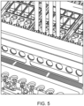
- FIG. 5 An illustration showing the capping of RVs with RV caps by a robotic pipettor is provided in FIG. 5 .
- the pipettor has four barrels, each of which is pushing an RV cap into a respective RV in a sample preparation cartridge at a sample preparation unit.
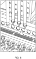
- FIG. 6 shows the transport of capped RVs from a sample preparation cartridge to RV wells of a sample analysis unit by a robotic pipettor.
- the distal ends of the 4 pipettor barrels are mated with the RV caps of the capped RVs, enabling the transport of the capped RVs by the robotic pipettor.
- sample preparation units are nucleic acid sample preparation units.
- Anucleic acid sample preparation unit includes one or more (e.g., two or more) sample preparation cartridges (e.g., any of the cartridges described herein), and a magnetic particle transfer component.
- a SPU of the present disclosure is present in an automated nucleic acid sample preparation and analysis system.
- the SPU may be present and employed in an automated system as described in e.g., WO 2017/161053 A1 , which claims priority to USSN 62/308,617 and USSN 62/357,772 .
- a magnetic particle transfer component may include a plunger magnet bar suspended above the one or more sample preparation cartridges, and a magnetic rod for each plurality of linearly arranged wells, the magnetic rod(s) attached to the plunger magnet bar and projecting from the plunger magnet bar toward the plurality of linearly arranged wells.
- the magnetic particle transfer component may further include a plunger bar suspended above the one or more sample preparation cartridges, the plunger bar including a plunger attachment point for each plurality of linearly arranged wells. The plunger bar is at a position lower than the plunger magnet bar, such that the magnetic rods are positioned above their corresponding plungers and capable of being inserted into and removed from bores of the plungers.
- the magnetic particle transfer component further includes a horizontal translation drive for translating the plunger magnet bar (and accordingly, magnetic rods) and the plunger bar (and accordingly, plungers, when present) across the plurality of linearly arranged wells.
- the magnetic particle transfer component further includes a vertical plunger magnet bar and plunger bar translation drive for coupled vertical translation of the plunger magnet bar and the plunger bar, and a vertical magnetic rod translation drive for independent vertical translation of the plunger magnet bar (and accordingly, magnetic rods), for inserting and removing the magnetic rod into a plunger attached to the plunger bar at the plunger bar attachment point.
- the plunger attachment point is a fork that couples with complementary grooves an upper portion of the plunger.
- the plunger bar may perform a movement prior to aligning with an element of the plunger to pick up the plunger, e.g., the plunger bar may perform a movement that repositions the plunger within the sample preparation cartridge.
- the plunger bar may perform a motion such that a portion of the plunger bar or an element attached thereto (e.g., a grasping component, such as the above-described fork) is used to tap down the plunger, e.g., to seat the plunger in the sample processing cartridge.
- a grasping component such as the above-described fork
- a nucleic acid sample preparation unit of the present disclosure may include a heater disposed beneath the plurality of linearly arranged wells, where the heater is movable between a first position and a second position.
- the heater is in thermal communication with one or more of the linearly arranged wells in the first position (so as to heat the wells (and accordingly, reagents therein) when in the first position) and not in thermal communication with any of the linearly arranged wells in the second position.
- SPU 700 includes three sample preparation cartridge sample preparation positions, two of which are occupied in FIG. 7 by sample preparation cartridges 702 and 704.
- SPU 700 performs the mechanical motions needed to extract nucleic acid.
- SPU 700 has features to pull the mixing plunger from the cartridge and move it to different wells along the sample preparation cartridge to mix reagents. Mixing takes place using the plunger attached to a vertically translating plunger bar.
- the magnetic rods and plungers of SPU 700 are attached to plunger magnet bar 716 and plunger bar 718, respectively.
- SPU 700 also has two independently controllable and movable heaters.
- First heater 706 is used to heat reagents in pretreatment and lysis wells.
- Second heater 708 is used to heat fluid in an elution well. Both heaters can be engaged during mixing in their respective wells.
- SPU 700 moves magnetic particles from one well to another by inserting a magnet into the plunger which attracts particles to the external wall of the plunger. Once the particles are magnetically attached to the plunger, they may be moved to the next well. The particles are released by removing the magnet from inside the plunger. Vertical motion of the plunger by SPU 700 causes mixing in the wells.
- the SPU includes Y-axis drive 710. Simultaneous/coupled vertical translation of the plungers and magnetic rods is effected by combination plunger bar and plunger magnet bar Z-axis drive 712. Independent vertical translation of the magnetic rods relative to the plungers is enabled by magnetic rod Z-axis drive 714. Drive 714 enables the insertion and removal of magnetic rods from their respective plungers during the sample preparation process.
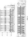
- FIG. 8 A side view of the SPU shown in FIG. 7 is illustrated in FIG. 8 .
- Shown in the top panel of FIG. 8 are 3 groups of 4 magnets 802, 3 groups of 4 plungers 804, and 3 groups of 4 SP cartridge wells 806 of SP cartridges for holding plungers.
- Shown at the bottom of FIG. 8 are the elements in their down-most position, in which the magnets and plungers are collapsed in wells of the SP cartridges. This position is suitable for capturing magnetic particles present in the wells on a lower external wall of the plungers, enabling transfer of the particles to different wells, and release of the particles into the wells upon removal of the magnetic rod(s) from the plunger(s).
- FIG. 8 Another view of the SP module shown in FIG. 7 is illustrated at the bottom of FIG. 8 .
- a magnetic rod is inserted into each plunger.
- the magnetic particles will attach to the outside wall of the plunger, enabling movement of the particles from well to well for washing and, ultimately, elution of nucleic acids from the particles.
Landscapes
- Chemical & Material Sciences (AREA)
- Health & Medical Sciences (AREA)
- Life Sciences & Earth Sciences (AREA)
- Engineering & Computer Science (AREA)
- General Health & Medical Sciences (AREA)
- Organic Chemistry (AREA)
- Analytical Chemistry (AREA)
- Chemical Kinetics & Catalysis (AREA)
- Zoology (AREA)
- Wood Science & Technology (AREA)
- Genetics & Genomics (AREA)
- Molecular Biology (AREA)
- Biochemistry (AREA)
- Clinical Laboratory Science (AREA)
- Bioinformatics & Cheminformatics (AREA)
- General Engineering & Computer Science (AREA)
- Biotechnology (AREA)
- Biomedical Technology (AREA)
- Proteomics, Peptides & Aminoacids (AREA)
- Microbiology (AREA)
- Biophysics (AREA)
- Physics & Mathematics (AREA)
- Hematology (AREA)
- Immunology (AREA)
- Plant Pathology (AREA)
- Crystallography & Structural Chemistry (AREA)
- Apparatus Associated With Microorganisms And Enzymes (AREA)
Claims (9)
- - Cartouche de préparation d'échantillons, comprenant :- un cadre, comprenant :- une première pluralité de puits intégrée à celui-ci, les puits de la première pluralité de puits ayant un fond fermé et un sommet ouvert ;- une première ouverture de récipient de réaction (RR) à l'intérieur du cadre ayant un premier RR disposé de façon amovible dans celle-ci ;- une première ouverture de capuchon de RR à l'intérieur du cadre ayant un premier capuchon de RR disposé de façon amovible dans celle-ci ;- une première ouverture de plongeur à l'intérieur du cadre comprenant un premier plongeur disposé de façon amovible dans celle-ci,dans laquelle la première ouverture de RR, la première ouverture de capuchon de RR et la première ouverture de plongeur sont ouvertes au fond, etdans laquelle la première pluralité de puits et la première ouverture de RR, la première ouverture de capuchon de RR et la première ouverture de plongeur sont disposées linéairement l'une par rapport à l'autre.
- - Cartouche de préparation d'échantillons selon la revendication 1, dans laquelle le cadre comprend en outre :- une deuxième pluralité de puits alignés linéairement, intégrée à l'intérieur du cadre, les puits de la deuxième pluralité de puits ayant un fond fermé et un sommet ouvert, et les puits de la deuxième pluralité de puits étant alignés linéairement avec :- une deuxième ouverture de RR à l'intérieur du cadre ayant un deuxième RR disposé de façon amovible dans celle-ci ;- une deuxième ouverture de capuchon de RR à l'intérieur du cadre ayant un deuxième capuchon de RR disposé de façon amovible dans celle-ci ;- une deuxième ouverture de plongeur à l'intérieur du cadre comprenant un deuxième plongeur disposé de façon amovible dans celle-ci,dans laquelle la deuxième ouverture de RR, la deuxième ouverture de capuchon de RR et la deuxième ouverture de plongeur sont ouvertes au fond.
- - Cartouche de préparation d'échantillons selon l'une des revendications 1 et 2, comprenant en outre :- une troisième pluralité de puits alignés linéairement, intégrée à l'intérieur du cadre, les puits de la troisième pluralité de puits ayant un fond fermé et un sommet ouvert, et les puits de la troisième pluralité de puits étant alignés linéairement avec :- une troisième ouverture de RR à l'intérieur du cadre ayant un troisième RR disposé de façon amovible dans celle-ci ;- une troisième ouverture de capuchon de RR à l'intérieur du cadre ayant un troisième capuchon de RR disposé de façon amovible dans celle-ci ;- une troisième ouverture de plongeur à l'intérieur du cadre comprenant un troisième plongeur disposé de façon amovible dans celle-ci,dans laquelle la troisième ouverture de RR, la troisième ouverture de capuchon de RR et la troisième ouverture de plongeur sont ouvertes au fond.
- - Cartouche de préparation d'échantillons selon l'une quelconque des revendications 1 à 3, comprenant en outre :- une quatrième pluralité de puits alignés linéairement, intégrée à l'intérieur du cadre, les puits de la quatrième pluralité de puits ayant un fond fermé et un sommet ouvert, et les puits de la quatrième pluralité de puits étant alignés linéairement avec :- une quatrième ouverture de RR à l'intérieur du cadre ayant un quatrième RR disposé de façon amovible dans celle-ci ;- une quatrième ouverture de capuchon de RR à l'intérieur du cadre ayant un quatrième capuchon de RR disposé de façon amovible dans celle-ci ;- une quatrième ouverture de plongeur à l'intérieur du cadre comprenant un quatrième plongeur disposé de façon amovible dans celle-ci,dans laquelle la quatrième ouverture de RR, la quatrième ouverture de capuchon de RR et la quatrième ouverture de plongeur sont ouvertes au fond.
- - Cartouche de préparation d'échantillons selon l'une quelconque des revendications 1 à 4, dans laquelle les ouvertures de RR, les ouvertures de capuchon de RR et les ouvertures de plongeur comprennent une caractéristique structurale qui fixe solidement et/ou aligne le RR le capuchon de RR et le plongeur dans leurs ouvertures respectives.
- - Cartouche de préparation d'échantillons selon l'une quelconque des revendications 1 à 5, comprenant au moins deux saillies de séparation de cartouches sur un côté supérieur du cadre et au moins deux saillies de séparation de cartouches sur un côté inférieur du cadre, les saillies de séparation de cartouches séparant la cartouche et une cartouche différente lorsque la cartouche et une cartouche différente sont empilées.
- - Cartouche de préparation d'échantillons selon la revendication 6, comprenant quatre saillies de séparation de cartouches sur le côté supérieur du cadre et quatre saillies de séparation de cartouches sur le côté inférieur du cadre.
- - Cartouche de préparation d'échantillons selon l'une quelconque des revendications 1 à 7, dans laquelle la pluralité de puits comprend de 2 à 10 puits.
- - Cartouche de préparation d'échantillons selon la revendication 8, dans laquelle la pluralité de puits comprend de 4 à 8 puits.
Applications Claiming Priority (2)
| Application Number | Priority Date | Filing Date | Title |
|---|---|---|---|
| US201662308618P | 2016-03-15 | 2016-03-15 | |
| PCT/US2017/022601 WO2017161056A1 (fr) | 2016-03-15 | 2017-03-15 | Cartouches de préparation d'échantillons et leurs procédés d'utilisation |
Publications (3)
| Publication Number | Publication Date |
|---|---|
| EP3429754A1 EP3429754A1 (fr) | 2019-01-23 |
| EP3429754A4 EP3429754A4 (fr) | 2019-12-04 |
| EP3429754B1 true EP3429754B1 (fr) | 2025-06-25 |
Family
ID=59852030
Family Applications (1)
| Application Number | Title | Priority Date | Filing Date |
|---|---|---|---|
| EP17767484.3A Active EP3429754B1 (fr) | 2016-03-15 | 2017-03-15 | Cartouches de préparation d'échantillons |
Country Status (6)
| Country | Link |
|---|---|
| US (1) | US11130983B2 (fr) |
| EP (1) | EP3429754B1 (fr) |
| JP (1) | JP6894453B2 (fr) |
| CN (1) | CN109562374B (fr) |
| CA (1) | CA3018093A1 (fr) |
| WO (1) | WO2017161056A1 (fr) |
Families Citing this family (8)
| Publication number | Priority date | Publication date | Assignee | Title |
|---|---|---|---|---|
| EP3430410B1 (fr) | 2016-03-15 | 2022-04-27 | Abbott Molecular Inc. | Procédé pour analyse automatisée |
| WO2017160980A1 (fr) | 2016-03-15 | 2017-09-21 | Abbott Laboratories | Dispositifs, systèmes et procédés de traitement d'échantillons |
| ES3041372T3 (en) | 2016-03-15 | 2025-11-11 | Abbott Molecular Inc | Systems of multi-assay processing and analysis |
| IT201800000969A1 (it) * | 2018-01-15 | 2019-07-15 | Bls Blue Lab Service Srl | Cartuccia per analisi multiparametriche di campioni |
| CN110564603A (zh) * | 2019-08-22 | 2019-12-13 | 南京艾瑞谱生物技术有限公司 | 一种一体化核酸检测器件及应用 |
| WO2021112855A1 (fr) * | 2019-12-05 | 2021-06-10 | Hewlett-Packard Development Company, L.P. | Étages de substrat présentant des nervures de coin |
| JP2024518331A (ja) | 2021-04-29 | 2024-05-01 | アボット・ラボラトリーズ | 生体試料のハイスループット核酸検査 |
| CN114606111A (zh) * | 2021-12-27 | 2022-06-10 | 宁波爱基因科技有限公司 | 一种核酸提取管结构、磁棒套及核酸提取方法 |
Citations (1)
| Publication number | Priority date | Publication date | Assignee | Title |
|---|---|---|---|---|
| US20090136386A1 (en) * | 2007-07-13 | 2009-05-28 | Handylab, Inc. | Rack for Sample Tubes and Reagent Holders |
Family Cites Families (24)
| Publication number | Priority date | Publication date | Assignee | Title |
|---|---|---|---|---|
| JPS57185953U (fr) * | 1981-05-21 | 1982-11-25 | ||
| ES2044997T3 (es) * | 1987-04-22 | 1994-01-16 | Abbott Lab | Aparato para sujetar cartuchos que contienen ensayos y otras muestras biologicas para ser utilizadas en un analizador de muestras biologicas. |
| US5035861A (en) * | 1987-04-22 | 1991-07-30 | Abbott Laboratories | Locking rack and disposable sample cartridge |
| US5605665A (en) | 1992-03-27 | 1997-02-25 | Abbott Laboratories | Reaction vessel |
| US5342581A (en) * | 1993-04-19 | 1994-08-30 | Sanadi Ashok R | Apparatus for preventing cross-contamination of multi-well test plates |
| JP4278885B2 (ja) * | 2000-05-25 | 2009-06-17 | 富士フイルム株式会社 | インクジェットプリンタ |
| US20020068022A1 (en) | 2000-12-04 | 2002-06-06 | Jinghua Schneider | Mini-tube rack |
| US20080014610A1 (en) * | 2004-06-02 | 2008-01-17 | Arkray,Inc. | Container for Nucleic Acid Extraction, Method of Cleaning Solid Matrix and Relevant Cleaning Mechanism, and Method of Purifying Nucleic Acid |
| JP4977708B2 (ja) * | 2005-09-06 | 2012-07-18 | フィンザイムズ・オサケユキテュア | サンプルプレートアセンブリおよび生体サンプルを処理する方法 |
| US7788683B2 (en) | 2007-01-05 | 2010-08-31 | Imation Corp. | Data storage cartridge and system including non-tape storage medium |
| JP5030672B2 (ja) * | 2007-06-06 | 2012-09-19 | 村角工業株式会社 | 医療検査用カセット |
| US8105783B2 (en) * | 2007-07-13 | 2012-01-31 | Handylab, Inc. | Microfluidic cartridge |
| GB0715171D0 (en) * | 2007-08-03 | 2007-09-12 | Enigma Diagnostics Ltd | Sample processor |
| US20090181359A1 (en) * | 2007-10-25 | 2009-07-16 | Lou Sheng C | Method of performing ultra-sensitive immunoassays |
| US8222048B2 (en) * | 2007-11-05 | 2012-07-17 | Abbott Laboratories | Automated analyzer for clinical laboratory |
| KR20130029128A (ko) * | 2010-07-23 | 2013-03-21 | 베크만 컬터, 인코포레이티드 | 실시간 pcr용 용기 |
| US8470153B2 (en) * | 2011-07-22 | 2013-06-25 | Tecan Trading Ag | Cartridge and system for manipulating samples in liquid droplets |
| EP2921861B1 (fr) * | 2012-11-16 | 2021-07-21 | Universal Bio Research Co., Ltd. | Dispositif de mise en oeuvre d'une réaction de type à mouvement linéaire et procédé associé |
| US9248448B2 (en) | 2013-04-24 | 2016-02-02 | William Marsh Rice University | Multisample bionanochip platform |
| EP2929939A1 (fr) | 2014-04-07 | 2015-10-14 | Yantai AusBio Laboratories Co., Ltd. | Microplaque |
| US9827567B2 (en) * | 2014-04-22 | 2017-11-28 | Nanosphere, Inc. | Diagnostic cartridges having flexible seals |
| WO2017160980A1 (fr) | 2016-03-15 | 2017-09-21 | Abbott Laboratories | Dispositifs, systèmes et procédés de traitement d'échantillons |
| US10648018B2 (en) | 2016-03-15 | 2020-05-12 | Abbott Molecular Inc | Reaction vessel systems and methods and systems for using same |
| EP3430410B1 (fr) | 2016-03-15 | 2022-04-27 | Abbott Molecular Inc. | Procédé pour analyse automatisée |
-
2017
- 2017-03-15 EP EP17767484.3A patent/EP3429754B1/fr active Active
- 2017-03-15 JP JP2018568169A patent/JP6894453B2/ja active Active
- 2017-03-15 CN CN201780026908.1A patent/CN109562374B/zh active Active
- 2017-03-15 CA CA3018093A patent/CA3018093A1/fr not_active Abandoned
- 2017-03-15 US US15/460,186 patent/US11130983B2/en active Active
- 2017-03-15 WO PCT/US2017/022601 patent/WO2017161056A1/fr not_active Ceased
Patent Citations (1)
| Publication number | Priority date | Publication date | Assignee | Title |
|---|---|---|---|---|
| US20090136386A1 (en) * | 2007-07-13 | 2009-05-28 | Handylab, Inc. | Rack for Sample Tubes and Reagent Holders |
Also Published As
| Publication number | Publication date |
|---|---|
| JP6894453B2 (ja) | 2021-06-30 |
| CN109562374A (zh) | 2019-04-02 |
| JP2019509061A (ja) | 2019-04-04 |
| US20170268038A1 (en) | 2017-09-21 |
| EP3429754A4 (fr) | 2019-12-04 |
| CA3018093A1 (fr) | 2017-09-21 |
| EP3429754A1 (fr) | 2019-01-23 |
| CN109562374B (zh) | 2021-09-07 |
| WO2017161056A1 (fr) | 2017-09-21 |
| US11130983B2 (en) | 2021-09-28 |
Similar Documents
| Publication | Publication Date | Title |
|---|---|---|
| EP3429754B1 (fr) | Cartouches de préparation d'échantillons | |
| US20240377423A1 (en) | Systems and Methods for Automated Analysis | |
| AU2023219975B2 (en) | Modules for transferring magnetic beads, automated system comprising the same and method for nucleic acid extraction using the same | |
| EP2192186B1 (fr) | Système et précédé pour l'extraction automatisée des acides nucléiques | |
| US9650626B2 (en) | Kit for nucleic acid extraction and a nucleic acid extractor | |
| US20230073882A1 (en) | System and apparatus for automated sample extracting of biological specimens | |
| US10648018B2 (en) | Reaction vessel systems and methods and systems for using same | |
| US20100248213A1 (en) | Collection/extraction container for biological material in forensic samples | |
| US9932574B2 (en) | Suspension container for binding particles for the isolation of biological material | |
| US10101354B2 (en) | Method for prevention of contamination during disposing of liquid by pipet array | |
| US20100159532A1 (en) | Method and device for performing a nucleic acid preparation and/or amplification | |
| EP2423688B1 (fr) | Conteneur de suspension pour des particules de liaison pour l'isolation de matériel biologique | |
| GB2618578A (en) | Method and consumable for nucleic acid extraction |
Legal Events
| Date | Code | Title | Description |
|---|---|---|---|
| STAA | Information on the status of an ep patent application or granted ep patent |
Free format text: STATUS: THE INTERNATIONAL PUBLICATION HAS BEEN MADE |
|
| PUAI | Public reference made under article 153(3) epc to a published international application that has entered the european phase |
Free format text: ORIGINAL CODE: 0009012 |
|
| STAA | Information on the status of an ep patent application or granted ep patent |
Free format text: STATUS: REQUEST FOR EXAMINATION WAS MADE |
|
| 17P | Request for examination filed |
Effective date: 20180920 |
|
| AK | Designated contracting states |
Kind code of ref document: A1 Designated state(s): AL AT BE BG CH CY CZ DE DK EE ES FI FR GB GR HR HU IE IS IT LI LT LU LV MC MK MT NL NO PL PT RO RS SE SI SK SM TR |
|
| AX | Request for extension of the european patent |
Extension state: BA ME |
|
| DAV | Request for validation of the european patent (deleted) | ||
| DAX | Request for extension of the european patent (deleted) | ||
| A4 | Supplementary search report drawn up and despatched |
Effective date: 20191105 |
|
| RIC1 | Information provided on ipc code assigned before grant |
Ipc: C12Q 1/6806 20180101ALI20191029BHEP Ipc: G01N 1/00 20060101ALI20191029BHEP Ipc: B01L 7/00 20060101ALI20191029BHEP Ipc: B01L 3/00 20060101AFI20191029BHEP Ipc: C12N 15/10 20060101ALI20191029BHEP Ipc: B01L 3/14 20060101ALI20191029BHEP Ipc: C12Q 1/00 20060101ALI20191029BHEP |
|
| STAA | Information on the status of an ep patent application or granted ep patent |
Free format text: STATUS: EXAMINATION IS IN PROGRESS |
|
| 17Q | First examination report despatched |
Effective date: 20230310 |
|
| P01 | Opt-out of the competence of the unified patent court (upc) registered |
Effective date: 20230530 |
|
| GRAP | Despatch of communication of intention to grant a patent |
Free format text: ORIGINAL CODE: EPIDOSNIGR1 |
|
| STAA | Information on the status of an ep patent application or granted ep patent |
Free format text: STATUS: GRANT OF PATENT IS INTENDED |
|
| INTG | Intention to grant announced |
Effective date: 20250127 |
|
| GRAS | Grant fee paid |
Free format text: ORIGINAL CODE: EPIDOSNIGR3 |
|
| GRAA | (expected) grant |
Free format text: ORIGINAL CODE: 0009210 |
|
| STAA | Information on the status of an ep patent application or granted ep patent |
Free format text: STATUS: THE PATENT HAS BEEN GRANTED |
|
| AK | Designated contracting states |
Kind code of ref document: B1 Designated state(s): AL AT BE BG CH CY CZ DE DK EE ES FI FR GB GR HR HU IE IS IT LI LT LU LV MC MK MT NL NO PL PT RO RS SE SI SK SM TR |
|
| REG | Reference to a national code |
Ref country code: GB Ref legal event code: FG4D |
|
| REG | Reference to a national code |
Ref country code: CH Ref legal event code: EP |
|
| REG | Reference to a national code |
Ref country code: CH Ref legal event code: EP |
|
| REG | Reference to a national code |
Ref country code: IE Ref legal event code: FG4D |
|
| REG | Reference to a national code |
Ref country code: DE Ref legal event code: R096 Ref document number: 602017090137 Country of ref document: DE |
|
| PG25 | Lapsed in a contracting state [announced via postgrant information from national office to epo] |
Ref country code: FI Free format text: LAPSE BECAUSE OF FAILURE TO SUBMIT A TRANSLATION OF THE DESCRIPTION OR TO PAY THE FEE WITHIN THE PRESCRIBED TIME-LIMIT Effective date: 20250625 |
|
| REG | Reference to a national code |
Ref country code: LT Ref legal event code: MG9D |
|
| PG25 | Lapsed in a contracting state [announced via postgrant information from national office to epo] |
Ref country code: GR Free format text: LAPSE BECAUSE OF FAILURE TO SUBMIT A TRANSLATION OF THE DESCRIPTION OR TO PAY THE FEE WITHIN THE PRESCRIBED TIME-LIMIT Effective date: 20250926 Ref country code: NO Free format text: LAPSE BECAUSE OF FAILURE TO SUBMIT A TRANSLATION OF THE DESCRIPTION OR TO PAY THE FEE WITHIN THE PRESCRIBED TIME-LIMIT Effective date: 20250925 |
|
| PG25 | Lapsed in a contracting state [announced via postgrant information from national office to epo] |
Ref country code: BG Free format text: LAPSE BECAUSE OF FAILURE TO SUBMIT A TRANSLATION OF THE DESCRIPTION OR TO PAY THE FEE WITHIN THE PRESCRIBED TIME-LIMIT Effective date: 20250625 |
|
| PG25 | Lapsed in a contracting state [announced via postgrant information from national office to epo] |
Ref country code: HR Free format text: LAPSE BECAUSE OF FAILURE TO SUBMIT A TRANSLATION OF THE DESCRIPTION OR TO PAY THE FEE WITHIN THE PRESCRIBED TIME-LIMIT Effective date: 20250625 |
|
| PG25 | Lapsed in a contracting state [announced via postgrant information from national office to epo] |
Ref country code: RS Free format text: LAPSE BECAUSE OF FAILURE TO SUBMIT A TRANSLATION OF THE DESCRIPTION OR TO PAY THE FEE WITHIN THE PRESCRIBED TIME-LIMIT Effective date: 20250925 |
|
| PG25 | Lapsed in a contracting state [announced via postgrant information from national office to epo] |
Ref country code: LV Free format text: LAPSE BECAUSE OF FAILURE TO SUBMIT A TRANSLATION OF THE DESCRIPTION OR TO PAY THE FEE WITHIN THE PRESCRIBED TIME-LIMIT Effective date: 20250625 |
|
| REG | Reference to a national code |
Ref country code: NL Ref legal event code: MP Effective date: 20250625 |
|
| PG25 | Lapsed in a contracting state [announced via postgrant information from national office to epo] |
Ref country code: NL Free format text: LAPSE BECAUSE OF FAILURE TO SUBMIT A TRANSLATION OF THE DESCRIPTION OR TO PAY THE FEE WITHIN THE PRESCRIBED TIME-LIMIT Effective date: 20250625 |
|
| PG25 | Lapsed in a contracting state [announced via postgrant information from national office to epo] |
Ref country code: PT Free format text: LAPSE BECAUSE OF FAILURE TO SUBMIT A TRANSLATION OF THE DESCRIPTION OR TO PAY THE FEE WITHIN THE PRESCRIBED TIME-LIMIT Effective date: 20251027 |
|
| REG | Reference to a national code |
Ref country code: AT Ref legal event code: MK05 Ref document number: 1805932 Country of ref document: AT Kind code of ref document: T Effective date: 20250625 |
|
| PG25 | Lapsed in a contracting state [announced via postgrant information from national office to epo] |
Ref country code: IS Free format text: LAPSE BECAUSE OF FAILURE TO SUBMIT A TRANSLATION OF THE DESCRIPTION OR TO PAY THE FEE WITHIN THE PRESCRIBED TIME-LIMIT Effective date: 20251025 |
|
| PG25 | Lapsed in a contracting state [announced via postgrant information from national office to epo] |
Ref country code: AT Free format text: LAPSE BECAUSE OF FAILURE TO SUBMIT A TRANSLATION OF THE DESCRIPTION OR TO PAY THE FEE WITHIN THE PRESCRIBED TIME-LIMIT Effective date: 20250625 Ref country code: SM Free format text: LAPSE BECAUSE OF FAILURE TO SUBMIT A TRANSLATION OF THE DESCRIPTION OR TO PAY THE FEE WITHIN THE PRESCRIBED TIME-LIMIT Effective date: 20250625 |
|
| PG25 | Lapsed in a contracting state [announced via postgrant information from national office to epo] |
Ref country code: CZ Free format text: LAPSE BECAUSE OF FAILURE TO SUBMIT A TRANSLATION OF THE DESCRIPTION OR TO PAY THE FEE WITHIN THE PRESCRIBED TIME-LIMIT Effective date: 20250625 |
|
| PG25 | Lapsed in a contracting state [announced via postgrant information from national office to epo] |
Ref country code: PL Free format text: LAPSE BECAUSE OF FAILURE TO SUBMIT A TRANSLATION OF THE DESCRIPTION OR TO PAY THE FEE WITHIN THE PRESCRIBED TIME-LIMIT Effective date: 20250625 |
|
| PG25 | Lapsed in a contracting state [announced via postgrant information from national office to epo] |
Ref country code: EE Free format text: LAPSE BECAUSE OF FAILURE TO SUBMIT A TRANSLATION OF THE DESCRIPTION OR TO PAY THE FEE WITHIN THE PRESCRIBED TIME-LIMIT Effective date: 20250625 |
|
| PG25 | Lapsed in a contracting state [announced via postgrant information from national office to epo] |
Ref country code: SK Free format text: LAPSE BECAUSE OF FAILURE TO SUBMIT A TRANSLATION OF THE DESCRIPTION OR TO PAY THE FEE WITHIN THE PRESCRIBED TIME-LIMIT Effective date: 20250625 |
|
| PG25 | Lapsed in a contracting state [announced via postgrant information from national office to epo] |
Ref country code: ES Free format text: LAPSE BECAUSE OF FAILURE TO SUBMIT A TRANSLATION OF THE DESCRIPTION OR TO PAY THE FEE WITHIN THE PRESCRIBED TIME-LIMIT Effective date: 20250625 |
|
| PGFP | Annual fee paid to national office [announced via postgrant information from national office to epo] |
Ref country code: GB Payment date: 20260211 Year of fee payment: 10 |
|
| PG25 | Lapsed in a contracting state [announced via postgrant information from national office to epo] |
Ref country code: DK Free format text: LAPSE BECAUSE OF FAILURE TO SUBMIT A TRANSLATION OF THE DESCRIPTION OR TO PAY THE FEE WITHIN THE PRESCRIBED TIME-LIMIT Effective date: 20250625 |
|
| PGFP | Annual fee paid to national office [announced via postgrant information from national office to epo] |
Ref country code: DE Payment date: 20260213 Year of fee payment: 10 |
|
| PG25 | Lapsed in a contracting state [announced via postgrant information from national office to epo] |
Ref country code: IT Free format text: LAPSE BECAUSE OF FAILURE TO SUBMIT A TRANSLATION OF THE DESCRIPTION OR TO PAY THE FEE WITHIN THE PRESCRIBED TIME-LIMIT Effective date: 20250625 |
|
| PGFP | Annual fee paid to national office [announced via postgrant information from national office to epo] |
Ref country code: FR Payment date: 20260209 Year of fee payment: 10 |