EP3430210B1 - Flammbeständiges bauelement zur verbindung von wärmeisolierten teilen eines gebäudes - Google Patents
Flammbeständiges bauelement zur verbindung von wärmeisolierten teilen eines gebäudes Download PDFInfo
- Publication number
- EP3430210B1 EP3430210B1 EP17713903.7A EP17713903A EP3430210B1 EP 3430210 B1 EP3430210 B1 EP 3430210B1 EP 17713903 A EP17713903 A EP 17713903A EP 3430210 B1 EP3430210 B1 EP 3430210B1
- Authority
- EP
- European Patent Office
- Prior art keywords
- fire
- construction element
- element according
- thermally insulating
- resistant
- Prior art date
- Legal status (The legal status is an assumption and is not a legal conclusion. Google has not performed a legal analysis and makes no representation as to the accuracy of the status listed.)
- Active
Links
Images


Classifications
-
- E—FIXED CONSTRUCTIONS
- E04—BUILDING
- E04C—STRUCTURAL ELEMENTS; BUILDING MATERIALS
- E04C1/00—Building elements of block or other shape for the construction of parts of buildings
- E04C1/42—Building elements of block or other shape for the construction of parts of buildings of glass or other transparent material
-
- E—FIXED CONSTRUCTIONS
- E04—BUILDING
- E04B—GENERAL BUILDING CONSTRUCTIONS; WALLS, e.g. PARTITIONS; ROOFS; FLOORS; CEILINGS; INSULATION OR OTHER PROTECTION OF BUILDINGS
- E04B1/00—Constructions in general; Structures which are not restricted either to walls, e.g. partitions, or floors or ceilings or roofs
- E04B1/003—Balconies; Decks
- E04B1/0038—Anchoring devices specially adapted therefor with means for preventing cold bridging
-
- E—FIXED CONSTRUCTIONS
- E04—BUILDING
- E04B—GENERAL BUILDING CONSTRUCTIONS; WALLS, e.g. PARTITIONS; ROOFS; FLOORS; CEILINGS; INSULATION OR OTHER PROTECTION OF BUILDINGS
- E04B1/00—Constructions in general; Structures which are not restricted either to walls, e.g. partitions, or floors or ceilings or roofs
- E04B1/62—Insulation or other protection; Elements or use of specified material therefor
- E04B1/74—Heat, sound or noise insulation, absorption, or reflection; Other building methods affording favourable thermal or acoustical conditions, e.g. accumulating of heat within walls
- E04B1/76—Heat, sound or noise insulation, absorption, or reflection; Other building methods affording favourable thermal or acoustical conditions, e.g. accumulating of heat within walls specifically with respect to heat only
- E04B1/78—Heat insulating elements
- E04B1/80—Heat insulating elements slab-shaped
Definitions
- the invention is related to a construction element applicable to the construction of buildings, in particular an element for connecting parts of a building that are thermally insulated from one another, e.g. between a concrete floor and a cantilevered floor of a balcony. These elements are also known as 'thermal breaks'.
- connections between internal parts of a building and cantilevered external parts, e.g. a concrete balcony floor need to be realized with a minimal impact on the insulation of the building.
- elements are known that consist of an elongate insulating portion provided with reinforcement bars that run through the insulating portion and absorb the tensile forces between the parts of the building that are to be connected. Means are also provided to absorb compression and shear forces. The latter may take the form of compression bars and bars running diagonally through the insulating portion, or of specially formed blocks that are incorporated into the insulating portion.
- the insulating portion is placed between the parts of the building which are to be connected, whilst the various force-absorbing elements are anchored in said building parts in order to form the connection.
- the thermally insulating material used in these elements is, for example, mineral wool such as rock wool or glass wool.
- mineral wool such as rock wool or glass wool.
- synthetic insulating materials such as PIR, PUR, EPS, XPS, or the like.
- PIR, PUR, EPS, XPS or the like.
- the latter have better thermal insulation properties than mineral wool and are thus preferred because the desired thermal insulation can be obtained with a lower density of insulation material than would be the case if rock or glass wool are used.
- materials such as PIR, PUR, and the like have lower fire resistance than the mineral wool variants.
- EP 0 892 118 A1 discloses a construction element according to the preamble of claim 1.
- the invention concerns a construction element as described in the appended claims.
- the invention concerns a construction element for forming a connection between two components of a building that are thermally insulated from one another.
- the element comprises an elongate portion comprising a thermally insulating material, bars running through the elongate portion in order to absorb tensile forces between the parts of the building, and means to absorb compression and shearing forces between the parts of the building.
- the construction element according to the invention is characterised in that the underside and part of the raised side walls of the elongate portion is formed by a fire-resistant profile with a undersurface and two raised side walls, and wherein a thermally insulating layer is provided on the base surface of the profile (i.e., between the raised side walls).
- the invention thus more specifically concerns a construction element for forming a connection between two components of a building that are thermally insulated from one another, comprising:
- the fire-resistant profile is made of a composite material, which may be a fire-resistant fibre cement, preferably having a thickness between 1 and 3 mm.
- the thermally insulating layer is formed of a material with a thermal conductivity lower than 0.06W/mK at 20°C.
- the thermally insulating layer may be formed of compressed rock wool.
- a fire-resistant profile with a base surface and two downward side walls is also provided at the top of the elongate portion, and a thermally insulating and preferably fire-resistant layer is also provided on the base surface of the uppermost profile (i.e., between the downward side walls).
- a number of support blocks may be provided, wherein the raised side walls of the fire-resistant profile are provided with notches in order to provide space for the supporting blocks.
- the thermally insulating material is preferably selected from the group of PIR, PUR, EPS, XPS, and equivalent materials.
- the thermally insulting material is selected from the group of PIR, PUR, EPS, XPS, and equivalent materials except in the areas above at least one or more of the support blocks, where the thermally insulating material consists of mineral wool, and wherein a tension bar passes through the mineral wool.
- Fig. 1a shows a cross-section of a construction element for creating a thermal break, as known from the prior art.
- the element consists of the following components: An elongate beam-shaped part 11 comprising a shell including a thermally insulating material 2, such as mineral wool or PIR (polyisocyanurate), PUR (polyurethane), EPS (expanded polystyrene), XPS (extruded polystyrene).
- the shell comprises metal side walls 3 located at the upper and lower parts of each of the sides of the beam-shaped portion 11, and of upper and lower sealing caps 4 formed of a synthetic materials, e.g., PVC.
- the shell it is also possible for the shell to form a contiguous whole that completely surrounds the insulating material.
- the beam-shamed portion 11 a number of bars 5 run through the beam-shaped portion 11. These bars are configured to absorb the tensile force between the connected parts of a building.
- the bars 5 are usually made of steel, and pass through openings in the metal side walls 3, where the bars are welded to these metal walls in order to provide a provisional connection between the bars and the walls. 'Provisional' means that: this connection serves to secure the bars relative to the beam-shaped portion 11 during the installation of the construction element.
- support elements 7 are provided to absorb compression and shearing forces.
- These are support blocks made of a solid material, e.g., concrete, with the shape of the block and the composition of the material provided so as to absorb both compression and shearing forces. In and of itself, this type of block is known, and it is described, e.g., in US 2013/0276393 .
- One or more bars 5 are provided above each of the support blocks 7. As shown in Fig. 1b , instead of these blocks 7, more conventional compression bars 8 and bars 9 passing diagonally through the insulation may also be provided, or a support block that is only configured to absorb compression forces may be combined with a diagonal 9.
- the construction element is placed in a building in the known manner by placing the insulating beam-shaped portion 11 between two parts of a building, e.g., between a first concrete floor inside the building and a second concrete floor that is connected to the building in a cantilevered manner, with the bars and other force-absorbing elements anchored in the concrete floors.
- a construction element according to one possible embodiment of the invention is shown in cross-section in fig. 2 .
- the element also comprises an elongate beam-shaped portion 11, filled with thermally insulating material 2.
- the underside and part of the side walls of the beam-shaped portion 11 is formed by a one-piece fire-resistant component 15 consisting of a flat undersurface 16 and two raised side walls 17.
- the fire-resistant portion 15 is formed of a rigid, fire-resistant material with low thickness, e.g., 1 - 3 mm thick.
- the part 15 thus forms a profile, more specifically a U-profile, of a given stiffness.
- a composite material is used for the fire-resistant profile 15.
- the profile is formed of a fibre cement, such as IPC (Inorganic Phosphate Cement) reinforced with fibreglass.
- a thermally insulating layer 18 that is for example 1.5 cm thick.
- the layer 18 is formed of material that is both thermally insulating and fire-resistant. This layer 18 completely covers the flat undersurface 16 of the profile.
- the thermally insulating layer 18 has a thermal conductivity lower than 0.06W/mK at 20°C.
- One material that is suitable for use as the layer 18 is compressed rock wool in a thickness of between 1 and 20 mm, preferably between 10 and 15 mm.
- the thermally insulating material 2 of the construction element is arranged.
- the construction element is sealed by a plastic sealing cap 4 and metal side walls 3, as in prior-art products.
- the supports 7 and the tension bars 5 are identical to those used in existing products.
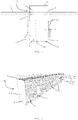
- Fig. 3 shows a 3D image of an embodiment of the construction element according to the invention, indicating the components described above. It can be seen that, when supporting blocks 7 are used, the fire-resistant profile 15 is provided with notches 20 in the raised side walls 17 in which the supporting blocks 7 are placed. These blocks are also often provided with guides 21 on the side walls (see fig. 2 ), into which the sides of the notches 20 can be slid.
- the fire-resistant profile 15 may also be applied in combination with the compression bars 8 and diagonal bars 9 shown in fig. 1b , or with other combinations, such as a block that absorbs compression forces together with a diagonal bar 9.
- the raised walls 17 of the fire-resistant profile 15 are high enough to cover the insulation material 2 laterally up to a certain height. Due to the fire-resistant effect of the fire-resistant profile 15 and the bottom layer 18 of the construction element, insulation material 2 with lower-level fire-resistant properties but high thermal insulation properties such as PIR, PUR, EPS, XPS, or equivalents, can be used for the construction element according to the invention.
- the construction element according to the invention thus offers the advantage that these high-quality materials may be used without compromising fire safety.
- the tension bars 5 may be made of steel. According to one embodiment, the tension bars, or at least part of the tension bars, are made of a non-metallic material, e.g., a material based on a resin containing basalt fibres. Other possible materials for the tension bars include materials based on glass fibres or Aramid polymers.
- FIG. 4 shows a version in which a fire-resistant profile 15 and a bottom layer 18 are provided not only at the bottom, but in which these components 15', 18' are also provided at the top of the construction element.
- Fig. 5 shows an embodiment in which, above one of the support blocks 7, a plastic support 25 is positioned that holds a piece of mineral wool 26 in place.
- the mineral wool part 26 is approximately as wide as the support block 7, and, like the support block 7, it is positioned perpendicular to the longitudinal direction of the profile 15.
- the support 25 is provided with an opening 27 through which a tension bar 5 can pass so that it passes through the mineral wool part 26.
- the rest of the insulation (not shown) then consists of PIR foam or equivalent.
- the local mineral wool insulation 26 provides a further improvement in fire safety due to this local shielding of the tension bars arranged above the support blocks 7.
- test pieces according to the invention were performed according to the European standard EN 1365-5:2005. Heating was carried out in accordance with the standard fire curve. The test pieces were heated from below. Four test pieces were tested according to the cross sections shown in fig. 1a, 1b , 2 , and 4 . Test pieces 1 and 2 are thus produced in accordance with the prior art with rock wool as the insulating material. Test pieces 2 and 3 are constructed according to the invention with PIR as the insulating material, and with a fire-resistant profile and a compressed rock wool layer at the top and/or at the bottom. The tests were carried out over a period of 120 min. The criteria of inadequate fire resistance that were verified were failure by subsidence and speed of subsidence.
- test pieces according to the invention are as fire-resistant as the known-art test pieces.
- the fire-resistant profile 15 and the compressed rock wool layer 18 confer the same fire resistance properties on the element with PIR as an element using rock wool as insulation.
Landscapes
- Engineering & Computer Science (AREA)
- Architecture (AREA)
- Physics & Mathematics (AREA)
- Civil Engineering (AREA)
- Structural Engineering (AREA)
- Electromagnetism (AREA)
- Acoustics & Sound (AREA)
- Building Environments (AREA)
- Agricultural Chemicals And Associated Chemicals (AREA)
- Medicinal Preparation (AREA)
Claims (12)
- Bauelement (10) zur Bildung einer Verbindung zwischen zwei Teilen eines Gebäudes, die voneinander wärmeisoliert sind, umfassend:- einen verlängerten Abschnitt (11), umfassend ein Wärmeisoliermaterial (2) und konfiguriert, um zwischen den Teilen des Gebäudes platziert zu sein,- Stangen (5, 6), die durch den verlängerten Abschnitt (11) verlaufen, und die konfiguriert sind, um in den Gebäudeteilen, die verbunden werden sollen, verankert zu sein und somit, um die Zugkräfte zwischen diesen Gebäudeteilen zu absorbieren,- Komponenten (7), um Kompressions- und Scherkräfte zwischen den Gebäudeteilen zu absorbieren,dadurch gekennzeichnet, dass die Unterseite und ein Teil der erhöhten Seitenwände des verlängerten Abschnitts (11) durch ein flammenbeständiges Profil (15) mit einer unteren Fläche (16) und zwei erhöhten Seitenwänden (17) gebildet sind, und wobei eine Wärmeisolierschicht (18) auf der unteren Fläche (16) des flammenbeständigen Profils (15) bereitgestellt ist.
- Bauelement nach Anspruch 1, wobei die Wärmeisolierschicht (18) ebenfalls flammenbeständig ist.
- Bauelement nach Anspruch 1 oder 2, wobei das flammenbeständige Profil (15) aus einem Verbundmaterial hergestellt ist.
- Bauelement nach Anspruch 3, wobei das Verbundmaterial ein flammenbeständiger Faserzement ist.
- Bauelement nach Anspruch 4, wobei die Dicke des flammenbeständigen Profils (15) zwischen 1 und 3 mm ist.
- Bauelement nach irgendeinem der vorhergehenden Ansprüche, wobei die Wärmeisolierschicht (18) aus einem Material mit einer Wärmeleitfähigkeit von weniger als 0,06 W/mk bei 20 °C ist.
- Bauelement nach irgendeinem der vorhergehenden Ansprüche, wobei die Wärmeisolierschicht (18) aus komprimierter Steinwolle hergestellt ist.
- Bauelement nach irgendeinem der vorhergehenden Ansprüche, wobei ein flammenbeständiges Profil (15') mit einer unteren Fläche und zwei nach unten gerichteten Seitenwänden auch an der oberen Seite des verlängerten Abschnitts (11) bereitgestellt ist, und wobei eine Wärmeisolierschicht (18') auch auf der unteren Fläche des obersten flammenbeständigen Profils (15') bereitgestellt ist.
- Bauelement nach Anspruch 8, wobei die Wärmeisolierschicht (18') an der oberen Seite des verlängerten Abschnitts (11) ebenfalls flammenbeständig ist.
- Bauelement nach irgendeinem der vorhergehenden Ansprüche, wobei eine Anzahl von Stützblöcken (7) als Mittel zum Absorbieren von Kompressions- und/oder Scherkräften bereitgestellt ist, und wobei die erhöhten Seitenwände (17) des flammenbeständigen Profils (15) mit Nuten (20) ausgestattet sind, um Raum für die Stützblöcke (7) bereitzustellen.
- Bauelement nach irgendeinem der vorhergehenden Ansprüche, wobei das Wärmeisoliermaterial (2) ausgewählt ist aus der Gruppe von PIR, PUR, EPS, XPS und ähnlichen Materialien.
- Bauelement nach Anspruch 9, wobei das Wärmeisoliermaterial ausgewählt ist aus der Gruppe von PIR, PUR, EPS, XPS und ähnlichen Materialien, außer in den Bereichen über mindestens einem oder mehreren der Stützblöcke (7), wobei das Wärmeisoliermaterial aus Mineralwolle (26) besteht, und wobei eine Zugstange (5) durch die Mineralwolle (26) verläuft.
Applications Claiming Priority (2)
| Application Number | Priority Date | Filing Date | Title |
|---|---|---|---|
| BE20165194A BE1023959B1 (nl) | 2016-03-17 | 2016-03-17 | Brandwerend constructie-element voor het realiseren van een verbinding tussen thermisch geisoleerde delen van een gebouw |
| PCT/EP2017/056298 WO2017158123A1 (en) | 2016-03-17 | 2017-03-16 | Fire-resistant construction element for connecting thermally insulated parts of a building |
Publications (2)
| Publication Number | Publication Date |
|---|---|
| EP3430210A1 EP3430210A1 (de) | 2019-01-23 |
| EP3430210B1 true EP3430210B1 (de) | 2022-05-04 |
Family
ID=55802112
Family Applications (1)
| Application Number | Title | Priority Date | Filing Date |
|---|---|---|---|
| EP17713903.7A Active EP3430210B1 (de) | 2016-03-17 | 2017-03-16 | Flammbeständiges bauelement zur verbindung von wärmeisolierten teilen eines gebäudes |
Country Status (6)
| Country | Link |
|---|---|
| US (1) | US20190093351A1 (de) |
| EP (1) | EP3430210B1 (de) |
| BE (1) | BE1023959B1 (de) |
| CA (1) | CA3015274A1 (de) |
| PL (1) | PL3430210T3 (de) |
| WO (1) | WO2017158123A1 (de) |
Families Citing this family (6)
| Publication number | Priority date | Publication date | Assignee | Title |
|---|---|---|---|---|
| RU177349U1 (ru) * | 2017-12-12 | 2018-02-16 | Михаил Александрович Дрыкин | Теплоизолирующая вставка для стыков элементов строительных конструкций |
| EP3737799B1 (de) * | 2018-01-10 | 2022-12-28 | Jencol Innovations, LLC | Thermische trennung für betonplatten |
| GB2575498A (en) * | 2018-07-12 | 2020-01-15 | Blackwood Benjamin | Universal concrete slab edge assembly |
| DE202021000466U1 (de) * | 2021-02-01 | 2021-04-22 | Halfen Gmbh | Einrichtung zur nachträglichen thermisch isolierenden, kraftübertragenden Anbindung eines zweiten lastaufnehmenden Bauwerksteils an ein erstes lastaufnehmendes Bauwerksteil und Bauwerk mit einer solchen Einrichtung |
| CA3225713A1 (en) * | 2023-01-11 | 2025-01-20 | Thermal B Solutions Inc. | Structural thermal break |
| EP4585758A1 (de) * | 2024-01-12 | 2025-07-16 | Peikko Group Oy | Bauelement zur wärmedämmung zwischen einem gebäudeteil und einem vorragenden aussenteil |
Citations (1)
| Publication number | Priority date | Publication date | Assignee | Title |
|---|---|---|---|---|
| EP0892118B1 (de) * | 1997-07-19 | 2006-04-05 | SCHÖCK BAUTEILE GmbH | Bauelement zur Wärmedämmung |
Family Cites Families (7)
| Publication number | Priority date | Publication date | Assignee | Title |
|---|---|---|---|---|
| CH676615A5 (de) * | 1988-04-22 | 1991-02-15 | Bau Box Ewiag | |
| DE4342673A1 (de) * | 1993-12-15 | 1995-06-22 | Schoeck Bauteile Gmbh | Bauelement zur Wärmedämmung |
| US7661231B2 (en) * | 2002-10-09 | 2010-02-16 | Michael E. Dalton | Concrete building system and method |
| DE102006011336A1 (de) * | 2006-03-09 | 2007-09-13 | Schöck Bauteile GmbH | Bauelement zur Wärmedämmung |
| PL2653625T3 (pl) | 2012-04-20 | 2019-05-31 | Halfen Gmbh | Termoizolacyjny element budowlany |
| US8973317B2 (en) * | 2013-05-13 | 2015-03-10 | James Larkin | Thermal break for concrete slab edges and balconies |
| US9598891B2 (en) * | 2015-03-23 | 2017-03-21 | Jk Worldwide Enterprises Inc. | Thermal break for use in construction |
-
2016
- 2016-03-17 BE BE20165194A patent/BE1023959B1/fr not_active IP Right Cessation
-
2017
- 2017-03-16 WO PCT/EP2017/056298 patent/WO2017158123A1/en not_active Ceased
- 2017-03-16 US US16/085,907 patent/US20190093351A1/en not_active Abandoned
- 2017-03-16 PL PL17713903.7T patent/PL3430210T3/pl unknown
- 2017-03-16 CA CA3015274A patent/CA3015274A1/en not_active Abandoned
- 2017-03-16 EP EP17713903.7A patent/EP3430210B1/de active Active
Patent Citations (1)
| Publication number | Priority date | Publication date | Assignee | Title |
|---|---|---|---|---|
| EP0892118B1 (de) * | 1997-07-19 | 2006-04-05 | SCHÖCK BAUTEILE GmbH | Bauelement zur Wärmedämmung |
Also Published As
| Publication number | Publication date |
|---|---|
| EP3430210A1 (de) | 2019-01-23 |
| PL3430210T3 (pl) | 2022-09-19 |
| CA3015274A1 (en) | 2017-09-21 |
| BE1023959A1 (nl) | 2017-09-21 |
| US20190093351A1 (en) | 2019-03-28 |
| WO2017158123A1 (en) | 2017-09-21 |
| BE1023959B1 (nl) | 2017-09-22 |
Similar Documents
| Publication | Publication Date | Title |
|---|---|---|
| EP3430210B1 (de) | Flammbeständiges bauelement zur verbindung von wärmeisolierten teilen eines gebäudes | |
| CA3010503C (en) | Construction element for connecting thermally insulated parts of a building | |
| JP6189943B2 (ja) | 発泡体壁断熱システム | |
| KR101552057B1 (ko) | 고하중용 열교차단 장치 | |
| KR101954652B1 (ko) | 이중 습식구조로 제작된 콘크리트 내화풍도슬래브 및 이의 제작방법 | |
| US20180179750A1 (en) | Roof structure and roof element | |
| US20220090380A1 (en) | Encapsulated prefabricated panel | |
| US20060272251A1 (en) | Composite floor system with fully-embedded studs | |
| KR102100394B1 (ko) | 전단 철근이 압축 부재를 관통하는 열교 차단 단열재 | |
| US20120324815A1 (en) | Construction panels | |
| US9297165B2 (en) | External wall with plaster and plaster carrier | |
| KR101375028B1 (ko) | 구조용 목재가 포함된 단열복합패널 및 그 단열복합패널을 이용한 벽체 시공 방법 | |
| EP2316641A1 (de) | "Isolierverbundstoff (KWI) mit einer Zweischicht-Struktur sowie eine Issolierverbundstoffhaltige (KWI) Überdachung" | |
| KR20200068919A (ko) | 중단열 벽체 구조의 안정성을 강화한 중단열 벽체 구조물과 시공법 | |
| EP2218841B1 (de) | Brandwand | |
| EP2314779B1 (de) | Laminierte Isolierplatte, Verwendung einer solchen Platte, und Verfahren zum Anordnen einer solchen Platte | |
| EP3580399B1 (de) | Fassade für ein gebäude, verfahren zur herstellung einer fassade und bausatz für eine fassade eines gebäudes | |
| WO2016171587A1 (ru) | Способ изготовления изделий с теплоизолирующим слоем для строительства зданий и сооружений | |
| KR102852612B1 (ko) | 슬래브 커튼월 선형조인트의 내화 채움 구조 시스템 | |
| KR102662980B1 (ko) | 내진부재가 구비된 지붕시스템 | |
| KR19990022895A (ko) | 고온 내성 절연요소 | |
| WO1997045604A1 (en) | A composite deck and a tray therefor | |
| IT202300000399U1 (it) | Pannello edile multistrato in materiale composito | |
| DK157086B (da) | Pladeformet tagelement | |
| CS272165B1 (cs) | Tepelně izolační panel a způsob jeho výroby |
Legal Events
| Date | Code | Title | Description |
|---|---|---|---|
| STAA | Information on the status of an ep patent application or granted ep patent |
Free format text: STATUS: UNKNOWN |
|
| STAA | Information on the status of an ep patent application or granted ep patent |
Free format text: STATUS: THE INTERNATIONAL PUBLICATION HAS BEEN MADE |
|
| PUAI | Public reference made under article 153(3) epc to a published international application that has entered the european phase |
Free format text: ORIGINAL CODE: 0009012 |
|
| STAA | Information on the status of an ep patent application or granted ep patent |
Free format text: STATUS: REQUEST FOR EXAMINATION WAS MADE |
|
| 17P | Request for examination filed |
Effective date: 20180810 |
|
| AK | Designated contracting states |
Kind code of ref document: A1 Designated state(s): AL AT BE BG CH CY CZ DE DK EE ES FI FR GB GR HR HU IE IS IT LI LT LU LV MC MK MT NL NO PL PT RO RS SE SI SK SM TR |
|
| AX | Request for extension of the european patent |
Extension state: BA ME |
|
| DAV | Request for validation of the european patent (deleted) | ||
| DAX | Request for extension of the european patent (deleted) | ||
| GRAP | Despatch of communication of intention to grant a patent |
Free format text: ORIGINAL CODE: EPIDOSNIGR1 |
|
| STAA | Information on the status of an ep patent application or granted ep patent |
Free format text: STATUS: GRANT OF PATENT IS INTENDED |
|
| INTG | Intention to grant announced |
Effective date: 20211115 |
|
| GRAS | Grant fee paid |
Free format text: ORIGINAL CODE: EPIDOSNIGR3 |
|
| GRAA | (expected) grant |
Free format text: ORIGINAL CODE: 0009210 |
|
| STAA | Information on the status of an ep patent application or granted ep patent |
Free format text: STATUS: THE PATENT HAS BEEN GRANTED |
|
| AK | Designated contracting states |
Kind code of ref document: B1 Designated state(s): AL AT BE BG CH CY CZ DE DK EE ES FI FR GB GR HR HU IE IS IT LI LT LU LV MC MK MT NL NO PL PT RO RS SE SI SK SM TR |
|
| REG | Reference to a national code |
Ref country code: GB Ref legal event code: FG4D |
|
| REG | Reference to a national code |
Ref country code: CH Ref legal event code: EP |
|
| REG | Reference to a national code |
Ref country code: AT Ref legal event code: REF Ref document number: 1489174 Country of ref document: AT Kind code of ref document: T Effective date: 20220515 |
|
| REG | Reference to a national code |
Ref country code: IE Ref legal event code: FG4D Ref country code: DE Ref legal event code: R096 Ref document number: 602017056868 Country of ref document: DE |
|
| REG | Reference to a national code |
Ref country code: FI Ref legal event code: FGE |
|
| REG | Reference to a national code |
Ref country code: NL Ref legal event code: FP |
|
| REG | Reference to a national code |
Ref country code: SE Ref legal event code: TRGR |
|
| REG | Reference to a national code |
Ref country code: LT Ref legal event code: MG9D |
|
| REG | Reference to a national code |
Ref country code: NO Ref legal event code: T2 Effective date: 20220504 |
|
| PG25 | Lapsed in a contracting state [announced via postgrant information from national office to epo] |
Ref country code: PT Free format text: LAPSE BECAUSE OF FAILURE TO SUBMIT A TRANSLATION OF THE DESCRIPTION OR TO PAY THE FEE WITHIN THE PRESCRIBED TIME-LIMIT Effective date: 20220905 Ref country code: LT Free format text: LAPSE BECAUSE OF FAILURE TO SUBMIT A TRANSLATION OF THE DESCRIPTION OR TO PAY THE FEE WITHIN THE PRESCRIBED TIME-LIMIT Effective date: 20220504 Ref country code: HR Free format text: LAPSE BECAUSE OF FAILURE TO SUBMIT A TRANSLATION OF THE DESCRIPTION OR TO PAY THE FEE WITHIN THE PRESCRIBED TIME-LIMIT Effective date: 20220504 Ref country code: GR Free format text: LAPSE BECAUSE OF FAILURE TO SUBMIT A TRANSLATION OF THE DESCRIPTION OR TO PAY THE FEE WITHIN THE PRESCRIBED TIME-LIMIT Effective date: 20220805 Ref country code: ES Free format text: LAPSE BECAUSE OF FAILURE TO SUBMIT A TRANSLATION OF THE DESCRIPTION OR TO PAY THE FEE WITHIN THE PRESCRIBED TIME-LIMIT Effective date: 20220504 Ref country code: BG Free format text: LAPSE BECAUSE OF FAILURE TO SUBMIT A TRANSLATION OF THE DESCRIPTION OR TO PAY THE FEE WITHIN THE PRESCRIBED TIME-LIMIT Effective date: 20220804 |
|
| PG25 | Lapsed in a contracting state [announced via postgrant information from national office to epo] |
Ref country code: RS Free format text: LAPSE BECAUSE OF FAILURE TO SUBMIT A TRANSLATION OF THE DESCRIPTION OR TO PAY THE FEE WITHIN THE PRESCRIBED TIME-LIMIT Effective date: 20220504 Ref country code: LV Free format text: LAPSE BECAUSE OF FAILURE TO SUBMIT A TRANSLATION OF THE DESCRIPTION OR TO PAY THE FEE WITHIN THE PRESCRIBED TIME-LIMIT Effective date: 20220504 Ref country code: IS Free format text: LAPSE BECAUSE OF FAILURE TO SUBMIT A TRANSLATION OF THE DESCRIPTION OR TO PAY THE FEE WITHIN THE PRESCRIBED TIME-LIMIT Effective date: 20220904 |
|
| PG25 | Lapsed in a contracting state [announced via postgrant information from national office to epo] |
Ref country code: SM Free format text: LAPSE BECAUSE OF FAILURE TO SUBMIT A TRANSLATION OF THE DESCRIPTION OR TO PAY THE FEE WITHIN THE PRESCRIBED TIME-LIMIT Effective date: 20220504 Ref country code: SK Free format text: LAPSE BECAUSE OF FAILURE TO SUBMIT A TRANSLATION OF THE DESCRIPTION OR TO PAY THE FEE WITHIN THE PRESCRIBED TIME-LIMIT Effective date: 20220504 Ref country code: RO Free format text: LAPSE BECAUSE OF FAILURE TO SUBMIT A TRANSLATION OF THE DESCRIPTION OR TO PAY THE FEE WITHIN THE PRESCRIBED TIME-LIMIT Effective date: 20220504 Ref country code: EE Free format text: LAPSE BECAUSE OF FAILURE TO SUBMIT A TRANSLATION OF THE DESCRIPTION OR TO PAY THE FEE WITHIN THE PRESCRIBED TIME-LIMIT Effective date: 20220504 Ref country code: DK Free format text: LAPSE BECAUSE OF FAILURE TO SUBMIT A TRANSLATION OF THE DESCRIPTION OR TO PAY THE FEE WITHIN THE PRESCRIBED TIME-LIMIT Effective date: 20220504 Ref country code: CZ Free format text: LAPSE BECAUSE OF FAILURE TO SUBMIT A TRANSLATION OF THE DESCRIPTION OR TO PAY THE FEE WITHIN THE PRESCRIBED TIME-LIMIT Effective date: 20220504 |
|
| REG | Reference to a national code |
Ref country code: DE Ref legal event code: R097 Ref document number: 602017056868 Country of ref document: DE |
|
| PLBE | No opposition filed within time limit |
Free format text: ORIGINAL CODE: 0009261 |
|
| STAA | Information on the status of an ep patent application or granted ep patent |
Free format text: STATUS: NO OPPOSITION FILED WITHIN TIME LIMIT |
|
| PG25 | Lapsed in a contracting state [announced via postgrant information from national office to epo] |
Ref country code: AL Free format text: LAPSE BECAUSE OF FAILURE TO SUBMIT A TRANSLATION OF THE DESCRIPTION OR TO PAY THE FEE WITHIN THE PRESCRIBED TIME-LIMIT Effective date: 20220504 |
|
| 26N | No opposition filed |
Effective date: 20230207 |
|
| PG25 | Lapsed in a contracting state [announced via postgrant information from national office to epo] |
Ref country code: SI Free format text: LAPSE BECAUSE OF FAILURE TO SUBMIT A TRANSLATION OF THE DESCRIPTION OR TO PAY THE FEE WITHIN THE PRESCRIBED TIME-LIMIT Effective date: 20220504 |
|
| REG | Reference to a national code |
Ref country code: AT Ref legal event code: UEP Ref document number: 1489174 Country of ref document: AT Kind code of ref document: T Effective date: 20220504 |
|
| PG25 | Lapsed in a contracting state [announced via postgrant information from national office to epo] |
Ref country code: MC Free format text: LAPSE BECAUSE OF FAILURE TO SUBMIT A TRANSLATION OF THE DESCRIPTION OR TO PAY THE FEE WITHIN THE PRESCRIBED TIME-LIMIT Effective date: 20220504 |
|
| PG25 | Lapsed in a contracting state [announced via postgrant information from national office to epo] |
Ref country code: LU Free format text: LAPSE BECAUSE OF NON-PAYMENT OF DUE FEES Effective date: 20230316 |
|
| REG | Reference to a national code |
Ref country code: IE Ref legal event code: MM4A |
|
| PG25 | Lapsed in a contracting state [announced via postgrant information from national office to epo] |
Ref country code: IT Free format text: LAPSE BECAUSE OF FAILURE TO SUBMIT A TRANSLATION OF THE DESCRIPTION OR TO PAY THE FEE WITHIN THE PRESCRIBED TIME-LIMIT Effective date: 20220504 Ref country code: IE Free format text: LAPSE BECAUSE OF NON-PAYMENT OF DUE FEES Effective date: 20230316 |
|
| PG25 | Lapsed in a contracting state [announced via postgrant information from national office to epo] |
Ref country code: BG Free format text: LAPSE BECAUSE OF FAILURE TO SUBMIT A TRANSLATION OF THE DESCRIPTION OR TO PAY THE FEE WITHIN THE PRESCRIBED TIME-LIMIT Effective date: 20220504 |
|
| PG25 | Lapsed in a contracting state [announced via postgrant information from national office to epo] |
Ref country code: BG Free format text: LAPSE BECAUSE OF FAILURE TO SUBMIT A TRANSLATION OF THE DESCRIPTION OR TO PAY THE FEE WITHIN THE PRESCRIBED TIME-LIMIT Effective date: 20220504 |
|
| PGFP | Annual fee paid to national office [announced via postgrant information from national office to epo] |
Ref country code: PL Payment date: 20250225 Year of fee payment: 9 |
|
| PGFP | Annual fee paid to national office [announced via postgrant information from national office to epo] |
Ref country code: CH Payment date: 20250401 Year of fee payment: 9 |
|
| PG25 | Lapsed in a contracting state [announced via postgrant information from national office to epo] |
Ref country code: CY Free format text: LAPSE BECAUSE OF FAILURE TO SUBMIT A TRANSLATION OF THE DESCRIPTION OR TO PAY THE FEE WITHIN THE PRESCRIBED TIME-LIMIT; INVALID AB INITIO Effective date: 20170316 |
|
| PG25 | Lapsed in a contracting state [announced via postgrant information from national office to epo] |
Ref country code: HU Free format text: LAPSE BECAUSE OF FAILURE TO SUBMIT A TRANSLATION OF THE DESCRIPTION OR TO PAY THE FEE WITHIN THE PRESCRIBED TIME-LIMIT; INVALID AB INITIO Effective date: 20170316 |
|
| PG25 | Lapsed in a contracting state [announced via postgrant information from national office to epo] |
Ref country code: TR Free format text: LAPSE BECAUSE OF FAILURE TO SUBMIT A TRANSLATION OF THE DESCRIPTION OR TO PAY THE FEE WITHIN THE PRESCRIBED TIME-LIMIT Effective date: 20220504 |
|
| PGFP | Annual fee paid to national office [announced via postgrant information from national office to epo] |
Ref country code: NL Payment date: 20260219 Year of fee payment: 10 |
|
| REG | Reference to a national code |
Ref country code: DE Ref legal event code: R081 Ref document number: 602017056868 Country of ref document: DE Owner name: LEVIAT NV, BE Free format text: FORMER OWNER: PLAKABETON NV, TERNAT, BE |
|
| REG | Reference to a national code |
Ref country code: CH Ref legal event code: U11 Free format text: ST27 STATUS EVENT CODE: U-0-0-U10-U11 (AS PROVIDED BY THE NATIONAL OFFICE) Effective date: 20260401 |
|
| PGFP | Annual fee paid to national office [announced via postgrant information from national office to epo] |
Ref country code: SE Payment date: 20260219 Year of fee payment: 10 |
|
| PGFP | Annual fee paid to national office [announced via postgrant information from national office to epo] |
Ref country code: GB Payment date: 20260220 Year of fee payment: 10 |
|
| PGFP | Annual fee paid to national office [announced via postgrant information from national office to epo] |
Ref country code: DE Payment date: 20260319 Year of fee payment: 10 Ref country code: NO Payment date: 20260223 Year of fee payment: 10 |
|
| PGFP | Annual fee paid to national office [announced via postgrant information from national office to epo] |
Ref country code: AT Payment date: 20260223 Year of fee payment: 10 |
|
| PGFP | Annual fee paid to national office [announced via postgrant information from national office to epo] |
Ref country code: FI Payment date: 20260219 Year of fee payment: 10 Ref country code: BE Payment date: 20260219 Year of fee payment: 10 |
|
| PGFP | Annual fee paid to national office [announced via postgrant information from national office to epo] |
Ref country code: FR Payment date: 20260220 Year of fee payment: 10 |