EP3430238B1 - Turbinenrotor mit einem belüftungsabstandshalter - Google Patents
Turbinenrotor mit einem belüftungsabstandshalter Download PDFInfo
- Publication number
- EP3430238B1 EP3430238B1 EP17716567.7A EP17716567A EP3430238B1 EP 3430238 B1 EP3430238 B1 EP 3430238B1 EP 17716567 A EP17716567 A EP 17716567A EP 3430238 B1 EP3430238 B1 EP 3430238B1
- Authority
- EP
- European Patent Office
- Prior art keywords
- rotor
- spacer
- radial flange
- hub
- passages
- Prior art date
- Legal status (The legal status is an assumption and is not a legal conclusion. Google has not performed a legal analysis and makes no representation as to the accuracy of the status listed.)
- Active
Links
Images
Classifications
-
- F—MECHANICAL ENGINEERING; LIGHTING; HEATING; WEAPONS; BLASTING
- F01—MACHINES OR ENGINES IN GENERAL; ENGINE PLANTS IN GENERAL; STEAM ENGINES
- F01D—NON-POSITIVE DISPLACEMENT MACHINES OR ENGINES, e.g. STEAM TURBINES
- F01D5/00—Blades; Blade-carrying members; Heating, heat-insulating, cooling or antivibration means on the blades or the members
- F01D5/02—Blade-carrying members, e.g. rotors
- F01D5/08—Heating, heat-insulating or cooling means
- F01D5/081—Cooling fluid being directed on the side of the rotor disc or at the roots of the blades
- F01D5/082—Cooling fluid being directed on the side of the rotor disc or at the roots of the blades on the side of the rotor disc
-
- F—MECHANICAL ENGINEERING; LIGHTING; HEATING; WEAPONS; BLASTING
- F01—MACHINES OR ENGINES IN GENERAL; ENGINE PLANTS IN GENERAL; STEAM ENGINES
- F01D—NON-POSITIVE DISPLACEMENT MACHINES OR ENGINES, e.g. STEAM TURBINES
- F01D11/00—Preventing or minimising internal leakage of working-fluid, e.g. between stages
- F01D11/02—Preventing or minimising internal leakage of working-fluid, e.g. between stages by non-contact sealings, e.g. of labyrinth type
-
- F—MECHANICAL ENGINEERING; LIGHTING; HEATING; WEAPONS; BLASTING
- F01—MACHINES OR ENGINES IN GENERAL; ENGINE PLANTS IN GENERAL; STEAM ENGINES
- F01D—NON-POSITIVE DISPLACEMENT MACHINES OR ENGINES, e.g. STEAM TURBINES
- F01D5/00—Blades; Blade-carrying members; Heating, heat-insulating, cooling or antivibration means on the blades or the members
- F01D5/02—Blade-carrying members, e.g. rotors
- F01D5/06—Rotors for more than one axial stage, e.g. of drum or multiple disc type; Details thereof, e.g. shafts, shaft connections
- F01D5/066—Connecting means for joining rotor-discs or rotor-elements together, e.g. by a central bolt, by clamps
-
- F—MECHANICAL ENGINEERING; LIGHTING; HEATING; WEAPONS; BLASTING
- F01—MACHINES OR ENGINES IN GENERAL; ENGINE PLANTS IN GENERAL; STEAM ENGINES
- F01D—NON-POSITIVE DISPLACEMENT MACHINES OR ENGINES, e.g. STEAM TURBINES
- F01D5/00—Blades; Blade-carrying members; Heating, heat-insulating, cooling or antivibration means on the blades or the members
- F01D5/02—Blade-carrying members, e.g. rotors
- F01D5/08—Heating, heat-insulating or cooling means
- F01D5/085—Heating, heat-insulating or cooling means cooling fluid circulating inside the rotor
- F01D5/088—Heating, heat-insulating or cooling means cooling fluid circulating inside the rotor in a closed cavity
-
- F—MECHANICAL ENGINEERING; LIGHTING; HEATING; WEAPONS; BLASTING
- F05—INDEXING SCHEMES RELATING TO ENGINES OR PUMPS IN VARIOUS SUBCLASSES OF CLASSES F01-F04
- F05D—INDEXING SCHEME FOR ASPECTS RELATING TO NON-POSITIVE-DISPLACEMENT MACHINES OR ENGINES, GAS-TURBINES OR JET-PROPULSION PLANTS
- F05D2260/00—Function
- F05D2260/20—Heat transfer, e.g. cooling
-
- F—MECHANICAL ENGINEERING; LIGHTING; HEATING; WEAPONS; BLASTING
- F05—INDEXING SCHEMES RELATING TO ENGINES OR PUMPS IN VARIOUS SUBCLASSES OF CLASSES F01-F04
- F05D—INDEXING SCHEME FOR ASPECTS RELATING TO NON-POSITIVE-DISPLACEMENT MACHINES OR ENGINES, GAS-TURBINES OR JET-PROPULSION PLANTS
- F05D2260/00—Function
- F05D2260/30—Retaining components in desired mutual position
- F05D2260/31—Retaining bolts or nuts
-
- Y—GENERAL TAGGING OF NEW TECHNOLOGICAL DEVELOPMENTS; GENERAL TAGGING OF CROSS-SECTIONAL TECHNOLOGIES SPANNING OVER SEVERAL SECTIONS OF THE IPC; TECHNICAL SUBJECTS COVERED BY FORMER USPC CROSS-REFERENCE ART COLLECTIONS [XRACs] AND DIGESTS
- Y02—TECHNOLOGIES OR APPLICATIONS FOR MITIGATION OR ADAPTATION AGAINST CLIMATE CHANGE
- Y02T—CLIMATE CHANGE MITIGATION TECHNOLOGIES RELATED TO TRANSPORTATION
- Y02T50/00—Aeronautics or air transport
- Y02T50/60—Efficient propulsion technologies, e.g. for aircraft
Definitions
- the invention relates generally to gas turbine engines, and more particularly to the ventilation of the stages of a turbine, for example a low pressure turbine of a turbomachine.
- Fields of application of the invention are turbojet and turboprop aircraft and industrial gas turbines.
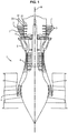
- FIG. 1 An example of a turbomachine has been illustrated in figure 1 .
- a turbomachine 1 typically comprises a nacelle which forms an opening for the admission of a determined flow of air towards the engine proper. Conventionally, the gases flow from upstream to downstream through the turbomachine.
- the turbomachine comprises one or more sections 4 for compressing the air admitted into the engine (generally a low pressure section and a high pressure section). The air thus compressed is admitted into the combustion chamber 5 and mixed with fuel before being burned there.
- the hot combustion gases from this combustion are then expanded in different stages of the turbine.
- a first expansion is made in a high pressure stage 6 immediately downstream of the combustion chamber 5 and which receives the gases at the highest temperature.
- the gases are expanded again by being guided through the so-called low pressure turbine stages 7.
- a turbine, low pressure 7 or high pressure 6 conventionally comprises one or more stages, each consisting of a row of fixed turbine blades, also called distributors, followed by a row of movable turbine blades, which form the rotor 3.
- the distributor 2 deflects the flow of gas taken from the combustion chamber 5 towards the blades turbine blades at an appropriate angle and speed to rotate these blades and the turbine rotor.
- the rotor includes several discs, for example four discs, which generally include peripheral grooves such as cells in which the movable blades are fitted.
- the turbine rotor is subjected to a very hot thermal environment, well above the maximum temperatures allowed by the rotor parts.
- the rotor generally comprises a sealing ring rotating with wipers fixed on the hub of each disc opposite which is placed a static part having a bore comprising an abradable material capable of withstanding high temperatures, in order to reduce convective exchanges between the flow of hot air from the air stream and the rotor.
- lunules are formed circumferentially on a downstream face of the radial flange of the sealing ring, in order to bring the flow of pressurized air to the cells through the cavity delimited by the hub. of the downstream disc and the sealing ring.
- These lunules which are depressions extending substantially radially with respect to the axis X of the turbomachine, are often machined in the mass of the sealing ring. Alternatively, they can be machined directly in the mass of the disc.
- their production is tedious and cannot be controlled with precision, so it is necessary to oversize them in order to guarantee a minimum section for ventilating the bottom of the cells.
- a ventilation system comprising through orifices, formed at the connection of two adjacent discs.
- the dimensioning section of this ventilation system then corresponds to that of the through orifices, which are easier and more precise to produce than lunules.
- This ventilation system thus ensures sufficient ventilation for the discs while limiting the air flow taken for this ventilation, thereby improving the performance of the turbomachine.
- An object of the invention is therefore to propose a system for ventilating the rotor of an element such as a low pressure turbine of a machine, which does not reduce the life of the rotor and does not weaken it entirely. by ensuring sufficient ventilation of these discs and by limiting the air flow taken for this ventilation.
- the spacer comprises a radially external edge opening into the ventilation cavity and a radially internal edge opening at the first element, at a distance from the ventilation cavity.
- Each passage comprises a through orifice formed in the spacer and opening at the level of the first element remote from the ventilation cavity.
- a groove extends between the through hole and the radially outer edge, a section of the through hole being larger than a section of the groove.
- the invention also proposes a turbine, in particular a low pressure turbine of a turbomachine, comprising a rotor as described above.
- a low pressure turbine 7 comprising a series of distributors 2 (or stators) alternated along the axis X of rotation of the turbomachine 1 with a series of mobile disks 3 of a rotor 3.
- the turbine 7 could comprise a different number of stages, and that the invention also finds application in any rotor of a member of a turbojet engine comprising a first element and a second element defining with the first element a ventilation cavity, such as a rotor of a high pressure turbine 6 which can be single or multi-stage or else of a high pressure or low pressure compressor.
- the turbine 7 conventionally comprises one or more stages (see figure 1 ), each consisting of a distributor 2 followed by a rotor 3 (or moving wheel).
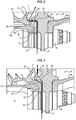
- the rotor 3 has an axis X of revolution which corresponds to a main axis of the turbomachine 1 and comprises several discs 30, by example four discs 30, which each comprise a hub 31 extending radially inwards towards the axis X. Peripheral grooves such as cells 32, in which the movable blades 34 are fitted, are formed in a rim 33 of the hubs 31.
- the various discs 30 of the rotor 3 can in particular be assembled coaxially by bolting. Each rotor disc 30 3 can be connected to an adjacent disc 30 by means of a ferrule 36.
- the second and third disc 30 (according to the direction of flow of the gases in the turbomachine) each comprise a ferrule 36 which extends from its downstream radial face and which is fixed to the disc 30 immediately downstream (this is i.e. the third and fourth disc 30, respectively).
- This ferrule 36 thus delimits a radially internal cavity 8 with the hub 31 immediately downstream.
- the ferrule 36 can in particular be fixed by bolting.
- the invention will be described in relation to the second and third disc 30 of the turbine 7.
- the invention applies to all the discs 30 of a turbine 7, and more particularly to the discs 30 comprised between the second disc 30 and the last disc 30 of the turbine 7 insofar as these discs 30 are all connected to the disc 30 immediately upstream via the ferrule 36 of this upstream disc 30.
- An annular sealing ring 20 sealing the passage of the cooling air flow F of the rims 33 of the discs 30 is also fixed on each disc.
- the sealing ring 20 can also provide a seal between the downstream of the movable blade and the upstream of the fixed blade immediately upstream.
- the sealing ring 20 comprises an internal radial flange 22 fixed on the hub 31 of the disc 30 and an external radial flange 24 in contact with the rim 33 of this disc 30.
- the flange internal radial 22 and the radial flange external 24 of the sealing ring 20 thus define with this disc 30 a ventilation cavity 9 of the rim 33 of the disc 30.
- the sealing ring 20 can conventionally include wipers.
- the internal radial flange 22 of the sealing ring 20 of the third disc 30 is fixed between the ferrule 36 of the second disc 30 and the hub 31 of the third disc 30.
- the ferrule 36 of the second disc 30 may comprise a substantially axial part 36a relative to the axis X, which extends towards the third disc 30 and delimits the internal cavity 8, and a radial part 36b by relative to the X axis which corresponds to the free end of the ferrule 36 and which is fixed to the hub 31 of the third disc 30.
- a flow of pressurized air F can be taken upstream of the turbine 7, typically at the high pressure compressor 4 of the turbomachine 1, and be introduced into the air cells 32 of their rim 33 in order to cool the discs 30.
- the rotor 3 comprises a ventilation system for each disc 30, adapted to put the radially internal cavity 8 and the ventilation cavity 9 in fluid communication.
- the rotor 3 comprises an annular spacer 40, attached and fixed between the internal radial flange 22 of the sealing ring 20 and the hub 31 of the disc 30 which comprises a series of through passages 42 axially configured to allow a injection of cooling fluid F into the ventilation cavity 9 from the radially internal cavity 8.
- the passages 42 extend substantially at least partially radially with respect to the axis X from a radially internal zone (adjacent to the axis X) towards a radially external zone (which is adjacent to the rim 33, when the first element comprises a hub 30) of the annular spacer 40.
- the passages 52 therefore form channels of circulation of the cooling fluid F from the radially internal cavity 8 to the ventilation cavity 9.
- the fixing of the sealing ring 20 on the first element, here the hub 31, is sealed, so that the flow of pressurized air F can only pass through the circulation channels thus formed.
- the fixing of an attached spacer 40 thus makes it possible to precisely calibrate the quantity of cooling fluid F (pressurized air) introduced into the ventilation cavity 9, the passages 42 being able to be produced, for example by machining, during a step distinct from the production of the discs 30 and without having to machine the discs 30 (or the sealing ring 20).
- the passages 42 therefore no longer constitute zones of weakness of the discs 30, which makes it possible to increase their service life, while ensuring their good cooling.
- spacer 40 also makes it possible to significantly reduce the cost of manufacturing the rotor 3 insofar as it makes it possible to limit, or even eliminate, the supplies necessary to ventilate the rim 33 and the control of which was particularly expensive.
- the spacer 40 is easy to produce and at a lower cost.
- the spacer 40 makes it possible to adjust the section of the ventilation flow at each passage 42.
- the spacer 40 can for example be fixed by bolting (screw and nut system 35) to the hub 31 and the internal radial flange 22, by means of fixing holes 22c formed in said internal radial flange 22.
- This method of attachment may be advantageous in particular when the internal radial flange 22 is itself fixed to the hub 31 by bolting, in which case it suffices to interpose the spacer 40 between the internal radial flange 22 and the hub 31.
- the spacer 40 can be fixed by shrinking, screwing, tightening, etc.
- the spacer 40 can be discontinuous and include several sub-parts 40 ' which are individually fixed between the internal radial flange 22 of the sealing ring 20 and the hub 31, typically at each bolting.
- the sub-parts 40 ' are fixed so as to provide a space E between two adjacent sub-parts 40', said spaces E defining the passages 42 for injecting the cooling fluid F from the radially internal cavity 8 in the ventilation cavity 9.
- the sub-parts 40 ′ may be of identical shape and size, or alternatively be separate in order to adjust the desired ventilation rates on a case-by-case basis.
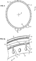
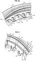
- the spacer 40 can be continuous, that is to say one piece and, if necessary, formed in one piece (as illustrated in particular on the Figures 4, 5a and 5b ).
- the passages 42 are formed in the spacer 40, for example by machining, drilling, etc.
- Each passage 42 can include, as illustrated in figure 5a , an orifice passing axially 43, formed in the spacer 40 and opening into the internal cavity 8, that is to say at the level of the hub 31 and at a distance (radially towards the axis X of the rotor) from the cavity ventilation 9, and a groove 44, extending substantially radially with respect to the axis X from the orifice 43 and opening into the ventilation cavity 9.
- the spacer 40 comprises a radially external edge 46 opening into the ventilation cavity 9 and a radially internal edge 45 opening into the internal cavity 8, at the hub 31.
- the through holes 43 are then formed at a distance from the two edges 45, 46, while the groove 44 is formed between the orifice 43 and the radially outer edge 46.
- the section of the groove 44 is chosen so as to allow sufficient ventilation of the discs 30 of the rotor 3 by taking a minimum of air flow upstream of the turbine 7 so as not to penalize the efficiency of the turbomachine. Consequently, it is the section of the grooves 44 which is dimensioning (calibrating).
- the section of the orifices 43 is simply chosen so as to be larger than the section of the grooves 44, in order to ensure a sufficient withdrawal of cooling fluid F in the internal cavity 8.
- the section can also be chosen so as to remain less than the hole section of the internal radial flange 22 opposite in order to limit the risk of error when mounting the screws in the holes.
- an orifice 43 whose cross section is smaller can serve as a polarizing device.
- the orifices 43 also make it possible to reduce the stresses. Indeed, these orifices 43 correspond to discharge holes. Due to their radius, they also make it possible to reduce the tangential mechanical stresses (predominant in a rotating part) which circulate in the spacer 40 by deflecting the flow of stresses progressively. Indeed, in the case of a dry order break, the flow is deflected very quickly, which generates significant mechanical stresses, detrimental to the life of the part. It will be noted that such forms are present in particular in the embodiment of the figure 4 , in which the spacer 40 is a continuous and monobloc piece over 360 °. These orifices 43 are however not necessary if the spacer 40 conforms to the embodiment illustrated in figure 6 .
- the section of the grooves 44 is chosen as a function of the stage of the corresponding disc 30 (second disc 30, third disc 30, etc.), the temperature of the turbine 7, the flow rate of the air stream through the turbomachine , etc. This choice being part of the usual work of a person skilled in the art, it will not be detailed further here.
- the cross section of the grooves 44 may be rectangular. Such a section is in fact easy to produce in comparison with lunulas which have spokes which are difficult to machine and reproduce. Furthermore, the groove 44 may include a groove only (groove 44 simple) or be composed of several grooves, parallel or not (groove 44 multiple).
- the through holes 43 may be of circular cross section. It is indeed very easy these days to control the section of an orifice when it is circular, since it suffices to determine its diameter.
- grooves 44 and the through orifices 43 may have a different section (triangular, oval, or any other shape of section).
- the groove 44 may be through or alternatively be blind.
- the internal radial flange 22 of the sealing ring 20 may comprise a strip 22a ( figure 5b ) substantially annular of which extend a series of tongues 22b or ears used for fixing the sealing ring 20 on the hub 31.
- the band 22a and the tongues 22b are, in one embodiment, in one piece and d '' in one piece.
- the sealing ring 20 can be bolted to the hub 31, in which case each tongue 22b comprises a through hole 22c configured to receive a rod of this fixing system.
- each orifice 43 of a passage 42 is located between two adjacent tongues 22b.
- the orifices 43 of the passages 42 therefore open on both sides into the internal cavity 8.
- the sealing ring 20 comprises, between the external radial flange 24 and the internal radial flange 22, a substantially axial flange 23, which forms a bend with the internal radial flange 22.
- the hub 31 also comprises, at this axial flange 23, an annular projection 38 which comes opposite ( figure 2 ) and pressing against ( figure 3 ) said axial flange 23.
- the spacer 40 also includes a bent portion 48 whose shape and dimensions correspond respectively to the shape and dimensions of the elbow of the sealing ring 20, so as to match the shape of the internal radial flange 22 and the axial flange 23 and at least partially cover the axial flange 23.
- This configuration thus allows the introduction of the coolant F into the ventilation cavity 9 despite the presence of the annular projection 38 of the hub 31 (see figures 2 and 3 ).
- the spacer 40 may comprise an annular plate 47, fixed along the internal radial flange 22, and a shoulder 48 extending from the annular plate 47 so as to come opposite the axial flange 23.
- the radially outer edge 46 of the spacer 40 then corresponds to the edge of the shoulder 48 and extends facing the radially outer surface of the axial flange 23 so that the passage 42 opens out well into the ventilation cavity 9.
- said groove 44 can be formed in the annular plate 47 and in the shoulder 48 of the spacer 40 and extend if necessary to its edge 46.
- lunules 26 ( figures 3 and 5a ), participating in the injection of cooling fluid F into the ventilation cavity 9, can also be formed in the sealing ring 20, more precisely in a part of the sealing ring 20 which faces the spacer 40.
- These lunules 26 can then have a larger section than the section of the passages 42 of the spacer 40, thereby increasing their manufacturing tolerance. It is then the section of the passages 42 formed in the spacer 40 which is dimensioning (or calibrating) for the quantity of cooling fluid F injected into the ventilation cavity 9, via the lunules 26.
- the cross section of the lunules 26 can therefore be chosen so as to be greater than the cross section of the passages 42, in order to bring the pressurized air flow F from the passages 42 to the ventilation cavity 9.
- the lunulas 26 are formed in the downstream face of the internal radial flange 22 ( figure 5a ).
- the lunules 26 can also be formed in the axial flange 23 in order to open into the ventilation cavity 9 and allow the passage 42 of the cooling fluid F.
- the spacer 40 can either extend only along the internal radial flange 22 and be substantially planar, or include a bent portion (shoulder 48) of shape corresponding to the shape of the elbow of the ring. sealing 20.
- the lunules 26 can be obtained by milling in the mass of the internal radial flange 22 (and if necessary of the axial flange 23).
- the spacer 40 may include an anti-rotation stopper, configured to prevent the spacer 40 (or the subparts 40 'of spacer 40) from rotating during operation of the rotor 3.
- an anti-rotation stopper configured to prevent the spacer 40 (or the subparts 40 'of spacer 40) from rotating during operation of the rotor 3.
- said shoulder 48 makes it possible to limit the radial deflections of the spacer 40 and thus form an anti-rotation stop.
- ventilation spacer 40 of the invention can be applied to other parts of a turbomachine requiring calibrated ventilation, and is not limited to its application to a rotor of a turbine.
Landscapes
- Engineering & Computer Science (AREA)
- Mechanical Engineering (AREA)
- General Engineering & Computer Science (AREA)
- Turbine Rotor Nozzle Sealing (AREA)
Claims (13)
- Rotor (3) eines Elements (7) einer Turbomaschine (1), zum Beispiel Rotor einer Turbine (7), wobei der Rotor (3) Folgendes umfasst:- ein erstes Element (30),- ein zweites Element (20), das mit dem ersten Element einen Lüftungshohlraum (9) definiert, und- einen Abstandshalter (40), der zwischen dem ersten Element (30) und dem zweiten Element (20) angesetzt und befestigt ist und eine Reihe von Durchgangskanälen (42) umfasst, die so konfiguriert sind, dass sie eine Einspritzung von Kühlmittel (F) in den Lüftungshohlraum (9) ermöglichen, wobei der Abstandshalter (40) einen radial äußeren Rand (46) umfasst, der in den Lüftungshohlraum (9) führt, und einen radial inneren Rand (45), der zum ersten Element (30) in Entfernung vom Lüftungshohlraum (9) führt,wobei der Rotor (3) dadurch gekennzeichnet ist, dass jeder Durchgangskanal (42) eine Durchgangsöffnung (43) umfasst, die im Abstandshalter (40) ausgebildet ist und am ersten Element in Entfernung vom Lüftungshohlraum (9) mündet, und eine Nut (44), die sich zwischen der Durchgangsöffnung (43) und dem radial äußeren Rand (46) erstreckt, wobei ein Abschnitt der Durchgangsöffnung (43) größer ist als ein Abschnitt der Nut (44).
- Rotor nach Anspruch 1, wobei der Abstandshalter (40) ringförmig ist und wobei der Abstandshalter (40) zwischen einem inneren Radialflansch (22) und dem ersten Element (30) angesetzt und befestigt ist.
- Rotor (3) nach Anspruch 1 oder 2, wobei der Abstandshalter (40) unterbrochen ist und mehrere Unterabschnitte (40') aufweist, die zwischen dem inneren Radialflansch (22) und dem ersten Element (30) befestigt sind, wobei die Durchgangskanäle (42) so ausgeführt werden, dass zwischen zwei anschließenden Unterabschnitten (40') ein Raum (E) gelassen wird.
- Rotor (3) nach einem beliebigen der vorstehenden Ansprüche 1 bis 3, wobei das erste Element (30) eine Ringscheibe (30) umfasst, die eine Nabe (31) und eine Felge (33) aufweist, wobei die Felge (33) so konfiguriert ist, dass sie Schaufelblätter (34) des Elements aufnimmt.
- Rotor nach Anspruch 4, wobei das zweite Element (20) einen Dichtungsring (20) umfasst, der einen inneren Radialflansch (22) aufweist, der auf der Nabe (31) befestigt ist und einen äußeren Radialflansch (24) in Berührung mit der Felge (33) umfasst, wobei der Dichtungsring (20) mit der Scheibe (30) den Belüftungshohlraum (9) der Felge (33) definiert.
- Rotor (3) nach einem beliebigen der vorstehenden Ansprüche 4 oder 5, wobei die Durchgangsöffnung (43) jedes Durchgangskanals an der Nabe (31) in Entfernung vom Lüftungshohlraum (9) mündet.
- Rotor (3) nach Anspruch 6, wobei der radiale Innenrand (45) zur Nabe (31) führt.
- Rotor (3) nach Anspruch 7, wobei die Nut (44) durchgehend ist.
- Rotor (3) nach einem beliebigen der vorstehenden Ansprüche 1 bis 8, wobei in dem zweiten Element (20) eine Reihe von Öffnungen (26) ausgebildet sind und der Abstandshalter (40) so zwischen dem ersten Element (30) und dem zweiten Element (20) befestigt ist, dass die Durchgangskanäle (42) den Öffnungen (26) zugewandt sind.
- Rotor (3) nach einem beliebigen der Ansprüche 5 bis 8, wobei eine Reihe von Öffnungen (26) im inneren Radialflansch (22) des Dichtungsrings (20) ausgebildet sind und der Abstandshalter (40) so zwischen der Nabe (31) und dem inneren Radialflansch (22) befestigt ist, dass die Durchgangskanäle (42) den Öffnungen (26) zugewandt sind.
- Rotor (3) nach einem beliebigen der vorstehenden Ansprüche 7 bis 10, wobei- der innere Radialflansch (22) des Dichtungsrings (20) abgewinkelt ist und einen axialen Teil (23) anschließend an den äußeren Radialflansch (24) umfasst,- der Abstandshalter (40) abgewinkelt ist und eine Schulter (48) aufweist, die so geformt ist, dass sie dem Axialteil (23) des inneren Radialflansches (22) zugewandt ist, und- sich die Nut (44) der Durchgangskanäle (42) bis zur Schulter (48) des Abstandshalters (40) erstreckt.
- Rotor (3) nach einem beliebigen der vorstehenden Ansprüche 4 bis 11, wobei der innere Radialflansch (22) eine Reihe von Zungenelementen (22b) umfasst und durch die Zungenelemente (22b) an der Nabe (31) befestigt ist, und wobei der Abstandshalter (40) am inneren Radialflansch (22) befestigt ist, so dass sich die Durchgangskanäle (42) zwischen zwei anschließenden Zungenelementen (22b) erstrecken.
- Turbine (7), insbesondere Niederdruckturbine (7) einer Turbomaschine, die einen Rotor (3) nach einem beliebigen der vorstehenden Ansprüche 1 bis 12 umfasst.
Applications Claiming Priority (2)
| Application Number | Priority Date | Filing Date | Title |
|---|---|---|---|
| FR1652234A FR3048998B1 (fr) | 2016-03-16 | 2016-03-16 | Rotor de turbine comprenant une entretoise de ventilation |
| PCT/FR2017/050614 WO2017158304A1 (fr) | 2016-03-16 | 2017-03-16 | Rotor de turbine comprenant une entretoise de ventilation |
Publications (2)
| Publication Number | Publication Date |
|---|---|
| EP3430238A1 EP3430238A1 (de) | 2019-01-23 |
| EP3430238B1 true EP3430238B1 (de) | 2020-01-08 |
Family
ID=56322062
Family Applications (1)
| Application Number | Title | Priority Date | Filing Date |
|---|---|---|---|
| EP17716567.7A Active EP3430238B1 (de) | 2016-03-16 | 2017-03-16 | Turbinenrotor mit einem belüftungsabstandshalter |
Country Status (5)
| Country | Link |
|---|---|
| US (1) | US10934846B2 (de) |
| EP (1) | EP3430238B1 (de) |
| CN (1) | CN108884714B (de) |
| FR (1) | FR3048998B1 (de) |
| WO (1) | WO2017158304A1 (de) |
Families Citing this family (4)
| Publication number | Priority date | Publication date | Assignee | Title |
|---|---|---|---|---|
| FR3062415B1 (fr) * | 2017-02-02 | 2019-06-07 | Safran Aircraft Engines | Rotor de turbine de turbomachine a ventilation par lamage |
| US10669875B2 (en) | 2018-03-28 | 2020-06-02 | Solar Turbines Incorporated | Cross key anti-rotation spacer |
| FR3092861B1 (fr) * | 2019-02-18 | 2023-02-10 | Safran Aircraft Engines | Ensemble de turbomachine comportant un taquet sur un jonc d'etancheite |
| FR3118989B1 (fr) * | 2021-01-21 | 2023-03-03 | Safran Aircraft Engines | Couronne de ventilation du support de palier arrière d'une turbomachine d'aéronef |
Family Cites Families (14)
| Publication number | Priority date | Publication date | Assignee | Title |
|---|---|---|---|---|
| US3043561A (en) * | 1958-12-29 | 1962-07-10 | Gen Electric | Turbine rotor ventilation system |
| US4523890A (en) * | 1983-10-19 | 1985-06-18 | General Motors Corporation | End seal for turbine blade base |
| US5350278A (en) * | 1993-06-28 | 1994-09-27 | The United States Of America As Represented By The Secretary Of The Air Force | Joining means for rotor discs |
| US5704764A (en) * | 1996-10-07 | 1998-01-06 | Westinghouse Electric Corporation | Turbine inter-disk cavity cooling air compressor |
| US6185925B1 (en) * | 1999-02-12 | 2001-02-13 | General Electric Company | External cooling system for turbine frame |
| US6283712B1 (en) * | 1999-09-07 | 2001-09-04 | General Electric Company | Cooling air supply through bolted flange assembly |
| DE50306044D1 (de) * | 2003-09-05 | 2007-02-01 | Siemens Ag | Schaufel einer Turbine |
| DE10355230A1 (de) * | 2003-11-26 | 2005-06-23 | Mtu Aero Engines Gmbh | Rotor für eine Turbomaschine |
| US7870742B2 (en) * | 2006-11-10 | 2011-01-18 | General Electric Company | Interstage cooled turbine engine |
| FR2948726B1 (fr) * | 2009-07-31 | 2013-07-05 | Snecma | Roue a aubes comprenant des moyens de refroidissement ameliores |
| FR2967453B1 (fr) * | 2010-11-17 | 2012-12-21 | Snecma | Disque de retention d'aubes |
| US20120134782A1 (en) * | 2010-11-30 | 2012-05-31 | Creston Lewis Dempsey | Purge systems for rotary machines and methods of assembling same |
| FR2978793B1 (fr) * | 2011-08-03 | 2015-12-04 | Snecma | Rotor de turbine pour une turbomachine |
| FR3019584B1 (fr) | 2014-04-07 | 2019-05-17 | Safran Aircraft Engines | Systeme de ventilation d'une turbine a l'aide d'orifices traversants et de lunules |
-
2016
- 2016-03-16 FR FR1652234A patent/FR3048998B1/fr active Active
-
2017
- 2017-03-16 CN CN201780022818.5A patent/CN108884714B/zh active Active
- 2017-03-16 EP EP17716567.7A patent/EP3430238B1/de active Active
- 2017-03-16 US US16/085,408 patent/US10934846B2/en active Active
- 2017-03-16 WO PCT/FR2017/050614 patent/WO2017158304A1/fr not_active Ceased
Non-Patent Citations (1)
| Title |
|---|
| None * |
Also Published As
| Publication number | Publication date |
|---|---|
| FR3048998B1 (fr) | 2019-12-13 |
| US20190085699A1 (en) | 2019-03-21 |
| US10934846B2 (en) | 2021-03-02 |
| WO2017158304A1 (fr) | 2017-09-21 |
| CN108884714B (zh) | 2021-08-31 |
| CN108884714A (zh) | 2018-11-23 |
| EP3430238A1 (de) | 2019-01-23 |
| FR3048998A1 (fr) | 2017-09-22 |
Similar Documents
| Publication | Publication Date | Title |
|---|---|---|
| FR3019584A1 (fr) | Systeme de ventilation d'une turbine a l'aide d'orifices traversants et de lunules | |
| FR3062415B1 (fr) | Rotor de turbine de turbomachine a ventilation par lamage | |
| EP3430238B1 (de) | Turbinenrotor mit einem belüftungsabstandshalter | |
| EP2406462B1 (de) | Rotorelement mit einem fluidkanal und einem kanalsperrglied sowie turbomotor mit dem rotorelement | |
| EP3421730B1 (de) | Turbine für strömungsmaschine mit dichtring bestehend aus zwei teilen | |
| EP2694781B1 (de) | Dichtring für eine turbinenstufe einer flugzeugturbomaschine mit geschlitzten drehschutzzapfen | |
| EP3880939A1 (de) | Abdichtung zwischen einer rotorscheibe und einem stator einer turbomaschine | |
| FR3001492A1 (fr) | Stator de turbomachine avec controle passif de la purge | |
| WO2023047034A1 (fr) | Turbine à gaz haute-pression pour une turbomachine et turbomachine | |
| EP3824221B1 (de) | Anordnung für eine turbomaschine | |
| EP4544155B1 (de) | Beschaufelte anordnung für turbomaschine, turbine für turbomaschine und turbomaschine | |
| FR2994453A1 (fr) | Ensemble a faible usure pour couronne aubagee de stator de turbomachine d'aeronef | |
| FR3097200A1 (fr) | Cone d’entree pour une turbomachine d’aeronef | |
| WO2014132001A1 (fr) | Réduction des échanges convectifs entre l'air et le rotor dans une turbine | |
| FR3084399A1 (fr) | Aube mobile pour une roue d'une turbomachine | |
| FR3129988A1 (fr) | Tuyere d’echappement de gaz de combustion pour une turbomachine d’aeronef | |
| WO2024194568A1 (fr) | Architecture pour joint d'etancheite de turbomachine | |
| WO2024194567A1 (fr) | Ensemble d'etancheite pour turbomachine | |
| FR3129987A1 (fr) | Tuyere d’echappement de gaz de combustion pour une turbomachine d’aeronef | |
| EP4314493A1 (de) | Turbinenringanordnung für eine turbomaschine | |
| WO2023156726A1 (fr) | Assemblage pour une turbomachine d'aéronef et turbomachine d'aéronef | |
| FR3113921A1 (fr) | Roue aubagée de turbomachine | |
| FR3074520A1 (fr) | Piece tournante pour turbomachine | |
| FR3027353A1 (fr) | Roue de turbomachine |
Legal Events
| Date | Code | Title | Description |
|---|---|---|---|
| STAA | Information on the status of an ep patent application or granted ep patent |
Free format text: STATUS: UNKNOWN |
|
| STAA | Information on the status of an ep patent application or granted ep patent |
Free format text: STATUS: THE INTERNATIONAL PUBLICATION HAS BEEN MADE |
|
| PUAI | Public reference made under article 153(3) epc to a published international application that has entered the european phase |
Free format text: ORIGINAL CODE: 0009012 |
|
| STAA | Information on the status of an ep patent application or granted ep patent |
Free format text: STATUS: REQUEST FOR EXAMINATION WAS MADE |
|
| 17P | Request for examination filed |
Effective date: 20181015 |
|
| AK | Designated contracting states |
Kind code of ref document: A1 Designated state(s): AL AT BE BG CH CY CZ DE DK EE ES FI FR GB GR HR HU IE IS IT LI LT LU LV MC MK MT NL NO PL PT RO RS SE SI SK SM TR |
|
| AX | Request for extension of the european patent |
Extension state: BA ME |
|
| DAV | Request for validation of the european patent (deleted) | ||
| DAX | Request for extension of the european patent (deleted) | ||
| GRAP | Despatch of communication of intention to grant a patent |
Free format text: ORIGINAL CODE: EPIDOSNIGR1 |
|
| STAA | Information on the status of an ep patent application or granted ep patent |
Free format text: STATUS: GRANT OF PATENT IS INTENDED |
|
| INTG | Intention to grant announced |
Effective date: 20190722 |
|
| GRAS | Grant fee paid |
Free format text: ORIGINAL CODE: EPIDOSNIGR3 |
|
| GRAA | (expected) grant |
Free format text: ORIGINAL CODE: 0009210 |
|
| STAA | Information on the status of an ep patent application or granted ep patent |
Free format text: STATUS: THE PATENT HAS BEEN GRANTED |
|
| AK | Designated contracting states |
Kind code of ref document: B1 Designated state(s): AL AT BE BG CH CY CZ DE DK EE ES FI FR GB GR HR HU IE IS IT LI LT LU LV MC MK MT NL NO PL PT RO RS SE SI SK SM TR |
|
| REG | Reference to a national code |
Ref country code: GB Ref legal event code: FG4D Free format text: NOT ENGLISH |
|
| REG | Reference to a national code |
Ref country code: CH Ref legal event code: EP |
|
| REG | Reference to a national code |
Ref country code: DE Ref legal event code: R096 Ref document number: 602017010719 Country of ref document: DE |
|
| REG | Reference to a national code |
Ref country code: IE Ref legal event code: FG4D Free format text: LANGUAGE OF EP DOCUMENT: FRENCH |
|
| REG | Reference to a national code |
Ref country code: AT Ref legal event code: REF Ref document number: 1222955 Country of ref document: AT Kind code of ref document: T Effective date: 20200215 |
|
| REG | Reference to a national code |
Ref country code: SE Ref legal event code: TRGR |
|
| REG | Reference to a national code |
Ref country code: NL Ref legal event code: MP Effective date: 20200108 |
|
| REG | Reference to a national code |
Ref country code: LT Ref legal event code: MG4D |
|
| PG25 | Lapsed in a contracting state [announced via postgrant information from national office to epo] |
Ref country code: RS Free format text: LAPSE BECAUSE OF FAILURE TO SUBMIT A TRANSLATION OF THE DESCRIPTION OR TO PAY THE FEE WITHIN THE PRESCRIBED TIME-LIMIT Effective date: 20200108 Ref country code: NL Free format text: LAPSE BECAUSE OF FAILURE TO SUBMIT A TRANSLATION OF THE DESCRIPTION OR TO PAY THE FEE WITHIN THE PRESCRIBED TIME-LIMIT Effective date: 20200108 Ref country code: LT Free format text: LAPSE BECAUSE OF FAILURE TO SUBMIT A TRANSLATION OF THE DESCRIPTION OR TO PAY THE FEE WITHIN THE PRESCRIBED TIME-LIMIT Effective date: 20200108 Ref country code: NO Free format text: LAPSE BECAUSE OF FAILURE TO SUBMIT A TRANSLATION OF THE DESCRIPTION OR TO PAY THE FEE WITHIN THE PRESCRIBED TIME-LIMIT Effective date: 20200408 Ref country code: PT Free format text: LAPSE BECAUSE OF FAILURE TO SUBMIT A TRANSLATION OF THE DESCRIPTION OR TO PAY THE FEE WITHIN THE PRESCRIBED TIME-LIMIT Effective date: 20200531 Ref country code: FI Free format text: LAPSE BECAUSE OF FAILURE TO SUBMIT A TRANSLATION OF THE DESCRIPTION OR TO PAY THE FEE WITHIN THE PRESCRIBED TIME-LIMIT Effective date: 20200108 |
|
| PG25 | Lapsed in a contracting state [announced via postgrant information from national office to epo] |
Ref country code: LV Free format text: LAPSE BECAUSE OF FAILURE TO SUBMIT A TRANSLATION OF THE DESCRIPTION OR TO PAY THE FEE WITHIN THE PRESCRIBED TIME-LIMIT Effective date: 20200108 Ref country code: HR Free format text: LAPSE BECAUSE OF FAILURE TO SUBMIT A TRANSLATION OF THE DESCRIPTION OR TO PAY THE FEE WITHIN THE PRESCRIBED TIME-LIMIT Effective date: 20200108 Ref country code: IS Free format text: LAPSE BECAUSE OF FAILURE TO SUBMIT A TRANSLATION OF THE DESCRIPTION OR TO PAY THE FEE WITHIN THE PRESCRIBED TIME-LIMIT Effective date: 20200508 Ref country code: BG Free format text: LAPSE BECAUSE OF FAILURE TO SUBMIT A TRANSLATION OF THE DESCRIPTION OR TO PAY THE FEE WITHIN THE PRESCRIBED TIME-LIMIT Effective date: 20200408 Ref country code: GR Free format text: LAPSE BECAUSE OF FAILURE TO SUBMIT A TRANSLATION OF THE DESCRIPTION OR TO PAY THE FEE WITHIN THE PRESCRIBED TIME-LIMIT Effective date: 20200409 |
|
| REG | Reference to a national code |
Ref country code: DE Ref legal event code: R097 Ref document number: 602017010719 Country of ref document: DE |
|
| PG25 | Lapsed in a contracting state [announced via postgrant information from national office to epo] |
Ref country code: SK Free format text: LAPSE BECAUSE OF FAILURE TO SUBMIT A TRANSLATION OF THE DESCRIPTION OR TO PAY THE FEE WITHIN THE PRESCRIBED TIME-LIMIT Effective date: 20200108 Ref country code: RO Free format text: LAPSE BECAUSE OF FAILURE TO SUBMIT A TRANSLATION OF THE DESCRIPTION OR TO PAY THE FEE WITHIN THE PRESCRIBED TIME-LIMIT Effective date: 20200108 Ref country code: EE Free format text: LAPSE BECAUSE OF FAILURE TO SUBMIT A TRANSLATION OF THE DESCRIPTION OR TO PAY THE FEE WITHIN THE PRESCRIBED TIME-LIMIT Effective date: 20200108 Ref country code: SM Free format text: LAPSE BECAUSE OF FAILURE TO SUBMIT A TRANSLATION OF THE DESCRIPTION OR TO PAY THE FEE WITHIN THE PRESCRIBED TIME-LIMIT Effective date: 20200108 Ref country code: CZ Free format text: LAPSE BECAUSE OF FAILURE TO SUBMIT A TRANSLATION OF THE DESCRIPTION OR TO PAY THE FEE WITHIN THE PRESCRIBED TIME-LIMIT Effective date: 20200108 Ref country code: DK Free format text: LAPSE BECAUSE OF FAILURE TO SUBMIT A TRANSLATION OF THE DESCRIPTION OR TO PAY THE FEE WITHIN THE PRESCRIBED TIME-LIMIT Effective date: 20200108 Ref country code: ES Free format text: LAPSE BECAUSE OF FAILURE TO SUBMIT A TRANSLATION OF THE DESCRIPTION OR TO PAY THE FEE WITHIN THE PRESCRIBED TIME-LIMIT Effective date: 20200108 Ref country code: MC Free format text: LAPSE BECAUSE OF FAILURE TO SUBMIT A TRANSLATION OF THE DESCRIPTION OR TO PAY THE FEE WITHIN THE PRESCRIBED TIME-LIMIT Effective date: 20200108 |
|
| REG | Reference to a national code |
Ref country code: CH Ref legal event code: PL |
|
| PLBE | No opposition filed within time limit |
Free format text: ORIGINAL CODE: 0009261 |
|
| STAA | Information on the status of an ep patent application or granted ep patent |
Free format text: STATUS: NO OPPOSITION FILED WITHIN TIME LIMIT |
|
| REG | Reference to a national code |
Ref country code: AT Ref legal event code: MK05 Ref document number: 1222955 Country of ref document: AT Kind code of ref document: T Effective date: 20200108 |
|
| 26N | No opposition filed |
Effective date: 20201009 |
|
| REG | Reference to a national code |
Ref country code: BE Ref legal event code: MM Effective date: 20200331 |
|
| PG25 | Lapsed in a contracting state [announced via postgrant information from national office to epo] |
Ref country code: LU Free format text: LAPSE BECAUSE OF NON-PAYMENT OF DUE FEES Effective date: 20200316 |
|
| PG25 | Lapsed in a contracting state [announced via postgrant information from national office to epo] |
Ref country code: CH Free format text: LAPSE BECAUSE OF NON-PAYMENT OF DUE FEES Effective date: 20200331 Ref country code: AT Free format text: LAPSE BECAUSE OF FAILURE TO SUBMIT A TRANSLATION OF THE DESCRIPTION OR TO PAY THE FEE WITHIN THE PRESCRIBED TIME-LIMIT Effective date: 20200108 Ref country code: LI Free format text: LAPSE BECAUSE OF NON-PAYMENT OF DUE FEES Effective date: 20200331 Ref country code: IE Free format text: LAPSE BECAUSE OF NON-PAYMENT OF DUE FEES Effective date: 20200316 |
|
| PG25 | Lapsed in a contracting state [announced via postgrant information from national office to epo] |
Ref country code: PL Free format text: LAPSE BECAUSE OF FAILURE TO SUBMIT A TRANSLATION OF THE DESCRIPTION OR TO PAY THE FEE WITHIN THE PRESCRIBED TIME-LIMIT Effective date: 20200108 Ref country code: SI Free format text: LAPSE BECAUSE OF FAILURE TO SUBMIT A TRANSLATION OF THE DESCRIPTION OR TO PAY THE FEE WITHIN THE PRESCRIBED TIME-LIMIT Effective date: 20200108 Ref country code: BE Free format text: LAPSE BECAUSE OF NON-PAYMENT OF DUE FEES Effective date: 20200331 |
|
| PG25 | Lapsed in a contracting state [announced via postgrant information from national office to epo] |
Ref country code: TR Free format text: LAPSE BECAUSE OF FAILURE TO SUBMIT A TRANSLATION OF THE DESCRIPTION OR TO PAY THE FEE WITHIN THE PRESCRIBED TIME-LIMIT Effective date: 20200108 Ref country code: MT Free format text: LAPSE BECAUSE OF FAILURE TO SUBMIT A TRANSLATION OF THE DESCRIPTION OR TO PAY THE FEE WITHIN THE PRESCRIBED TIME-LIMIT Effective date: 20200108 Ref country code: CY Free format text: LAPSE BECAUSE OF FAILURE TO SUBMIT A TRANSLATION OF THE DESCRIPTION OR TO PAY THE FEE WITHIN THE PRESCRIBED TIME-LIMIT Effective date: 20200108 |
|
| PG25 | Lapsed in a contracting state [announced via postgrant information from national office to epo] |
Ref country code: MK Free format text: LAPSE BECAUSE OF FAILURE TO SUBMIT A TRANSLATION OF THE DESCRIPTION OR TO PAY THE FEE WITHIN THE PRESCRIBED TIME-LIMIT Effective date: 20200108 Ref country code: AL Free format text: LAPSE BECAUSE OF FAILURE TO SUBMIT A TRANSLATION OF THE DESCRIPTION OR TO PAY THE FEE WITHIN THE PRESCRIBED TIME-LIMIT Effective date: 20200108 |
|
| PGFP | Annual fee paid to national office [announced via postgrant information from national office to epo] |
Ref country code: IT Payment date: 20250218 Year of fee payment: 9 |
|
| PGFP | Annual fee paid to national office [announced via postgrant information from national office to epo] |
Ref country code: SE Payment date: 20260323 Year of fee payment: 10 |
|
| PGFP | Annual fee paid to national office [announced via postgrant information from national office to epo] |
Ref country code: GB Payment date: 20260317 Year of fee payment: 10 |
|
| PGFP | Annual fee paid to national office [announced via postgrant information from national office to epo] |
Ref country code: DE Payment date: 20260320 Year of fee payment: 10 |
|
| PGFP | Annual fee paid to national office [announced via postgrant information from national office to epo] |
Ref country code: FR Payment date: 20260324 Year of fee payment: 10 |