EP3430633B1 - Câble de transmission de signaux électriques - Google Patents
Câble de transmission de signaux électriques Download PDFInfo
- Publication number
- EP3430633B1 EP3430633B1 EP17711090.5A EP17711090A EP3430633B1 EP 3430633 B1 EP3430633 B1 EP 3430633B1 EP 17711090 A EP17711090 A EP 17711090A EP 3430633 B1 EP3430633 B1 EP 3430633B1
- Authority
- EP
- European Patent Office
- Prior art keywords
- cable
- wires
- line
- dielectric
- relative permittivity
- Prior art date
- Legal status (The legal status is an assumption and is not a legal conclusion. Google has not performed a legal analysis and makes no representation as to the accuracy of the status listed.)
- Active
Links
Images


Classifications
-
- H—ELECTRICITY
- H01—ELECTRIC ELEMENTS
- H01B—CABLES; CONDUCTORS; INSULATORS; SELECTION OF MATERIALS FOR THEIR CONDUCTIVE, INSULATING OR DIELECTRIC PROPERTIES
- H01B11/00—Communication cables or conductors
- H01B11/005—Quad constructions
-
- H—ELECTRICITY
- H01—ELECTRIC ELEMENTS
- H01B—CABLES; CONDUCTORS; INSULATORS; SELECTION OF MATERIALS FOR THEIR CONDUCTIVE, INSULATING OR DIELECTRIC PROPERTIES
- H01B11/00—Communication cables or conductors
- H01B11/02—Cables with twisted pairs or quads
- H01B11/06—Cables with twisted pairs or quads with means for reducing effects of electromagnetic or electrostatic disturbances, e.g. screens
-
- H—ELECTRICITY
- H01—ELECTRIC ELEMENTS
- H01B—CABLES; CONDUCTORS; INSULATORS; SELECTION OF MATERIALS FOR THEIR CONDUCTIVE, INSULATING OR DIELECTRIC PROPERTIES
- H01B11/00—Communication cables or conductors
- H01B11/02—Cables with twisted pairs or quads
- H01B11/06—Cables with twisted pairs or quads with means for reducing effects of electromagnetic or electrostatic disturbances, e.g. screens
- H01B11/08—Screens specially adapted for reducing cross-talk
-
- H—ELECTRICITY
- H01—ELECTRIC ELEMENTS
- H01B—CABLES; CONDUCTORS; INSULATORS; SELECTION OF MATERIALS FOR THEIR CONDUCTIVE, INSULATING OR DIELECTRIC PROPERTIES
- H01B7/00—Insulated conductors or cables characterised by their form
- H01B7/02—Disposition of insulation
- H01B7/0208—Cables with several layers of insulating material
- H01B7/0216—Two layers
-
- H—ELECTRICITY
- H01—ELECTRIC ELEMENTS
- H01B—CABLES; CONDUCTORS; INSULATORS; SELECTION OF MATERIALS FOR THEIR CONDUCTIVE, INSULATING OR DIELECTRIC PROPERTIES
- H01B3/00—Insulators or insulating bodies characterised by the insulating materials; Selection of materials for their insulating or dielectric properties
- H01B3/18—Insulators or insulating bodies characterised by the insulating materials; Selection of materials for their insulating or dielectric properties mainly consisting of organic substances
- H01B3/30—Insulators or insulating bodies characterised by the insulating materials; Selection of materials for their insulating or dielectric properties mainly consisting of organic substances plastics; resins; waxes
-
- H—ELECTRICITY
- H01—ELECTRIC ELEMENTS
- H01B—CABLES; CONDUCTORS; INSULATORS; SELECTION OF MATERIALS FOR THEIR CONDUCTIVE, INSULATING OR DIELECTRIC PROPERTIES
- H01B7/00—Insulated conductors or cables characterised by their form
- H01B7/02—Disposition of insulation
Definitions
- the invention relates to a cable for transmitting electrical signals with an outer jacket made of an electrically insulating material and at least N lines n with N ⁇ 2 and N ⁇ N . which are arranged inside the outer jacket, each line n with n ⁇ [1, N ] having a total of M wires made of an electrically conductive material with M ⁇ 1 and M ⁇ N .
- a cable for transmitting electrical signals contains wires made of a conductive material, each of which is surrounded by an electrical insulator for the purpose of mutual electrical insulation.
- Electrical insulators have dielectric properties and essentially determine the propagation or conduction properties of the cable for electrical signals, which are essentially are electromagnetic waves.
- An essential property of dielectric materials or a dielectric is their permittivity ⁇ .
- the permittivity ⁇ (from lat. Permittere: allow, leave, let through), also called “dielectric conductivity” or “dielectric function”, indicates the permeability of a material to electric fields.
- a permittivity is also assigned to the vacuum, since electric fields can also set in the vacuum or electromagnetic fields can spread.
- star quad cable In order to reduce the crosstalk of electric signals from one line to another line within a cable, without this necessarily an additional shielding casing for each line in the cable has to be the present, the so-called star quad cable has been proposed (engl .: T Wisted / Star Q uad (TQ); German: stranded star quad cable (hereinafter also referred to as "star quad").
- the star quad cable is like the STP cable (S hielded T Wisted P air; dt .: shielded twisted pair), and the UTP cable (U nshielded T Wisted P air; unshielded twisted pair) to the balanced copper cables.
- star quad cable two lines, each with two wires, each made of an electrically conductive material, are combined to form one cable.
- Each wire is surrounded by a dielectric and the four wires are stranded together in a cross shape, with opposite wires each forming a pair of wires in the cross-section of the star-quad cable, so that the star-quad cable has two wire pairs or lines.
- the four wires stranded together are surrounded by a common protective sheath, which can include braid or foil shielding.
- This mechanical structure determines the transmission parameters such as near and far crosstalk.
- This type of cable is characterized above all by its small diameter and the resulting small bending radius.
- a further advantage of star quad stranding is the higher packing density than with pair stranding.
- the star quad cable essentially corresponds to the UTP and STP cable and can be classified accordingly: Star quad cables in unshielded design are referred to as twisted quad (UTQ).
- UTQ twisted quad
- one wire with a jacket made of insulating material arranged around it forms a conductor and two wires or conductors each form a line.
- Two pairs of conductors or two lines are twisted together and then form two cross-stranded double conductors (one double conductor corresponds to one line).
- Two in the cross section of the star quad Opposing conductors or wires form a pair, an electrical signal being transmitted on each pair.
- the four conductors or wires in the cross section of the star quad are arranged at the corners of a square, the conductors or wires of a pair being arranged at diagonally opposite corners.
- conductor pairs or wire pairs standing perpendicular to one another it is meant that, seen in the cross section of the cable, a first straight line which runs through the center points of the conductors or wires of a pair is perpendicular to a second straight line which passes through the center points of the The other pair's conductor or wires run.
- pamphlet US 2010/307790 A1 relates to a cable with at least one pair of core conductors, each of which is formed from a conductor and a dielectric surrounding this conductor.
- the surrounding dielectric is formed in two parts with an inner dielectric and an outer dielectric.
- pamphlet US 2010/307790 A1 deals with the problem that the dielectrics of the two conductors should be colored differently. This is according to US 2010/307790 A1 problematic because the introduction of different color pigments into the respective dielectric results in different permittivities for the dielectrics.
- the core conductors are all identical and differ only in the color (“ hue ") of the outer dielectric.
- pamphlet JP H11 25765 A deals with the problem of different signal propagation times on different stranded wire pairs, if for different ones Wire pairs of different stranding lengths are formed. Runtime differences between stranded wire pairs with different stranding lengths are reduced in that the permittivity for the dielectric is chosen to be 0.1 or more greater for a wire pair with the greatest stranding length compared to a wire pair with the smallest stranding length in a cable with several stranded wire pairs becomes. This is said to improve the attenuation of the near-end crosstalk (crosstalk at the end of the cable at which the signal is fed in), since different stranding lengths can be maintained.
- the invention has for its object a cable of the above. kind of improving the crosstalk between two lines.
- the dielectrics of the wires of one line show a
- ⁇ r the relative permittivity of the respective dielectric surrounding the wires.
- the value for k (s) is different for different values for s ( k (1) ⁇ k (2) ... ⁇ k ( N - j ))
- the values of k (s) can also be identical for several subsets of values for s in the range from 1 to (Nj), so that, for example, there are three or more identical values for k (s) within a cable (if N is greater than or equal to) 4), the values for k (s) being different for different subsets.
- of approximately 0.3 can be achieved in a particularly simple and cost-effective manner in that the dielectric of the wires of at least one line made of polypropylene (PP; ⁇ r ⁇ 2.1) and the dielectric of the wires of at least one other line made of polyethylene (PE, ⁇ r ⁇ 2.4) is produced.
- PP polypropylene
- PE polyethylene
- a value that deviates in total for the relative permittivity ⁇ r of the dielectric of the wires of a line with a targeted setting of a value for k for the deviation of the value for the relative permittivity ⁇ r of the dielectric of the wires of another line can be achieved in a simple manner in that the dielectric of the wires of at least one line is made up of a concentric layer structure of two or more dielectric materials with different values for the relative permittivity ⁇ r .
- a particularly advantageous setting of the value for the relative permittivity ⁇ r of the dielectric of the wires of a line with high effectiveness is achieved in that with the wires of at least one line there is a space between the wires of this line and the outer jacket facing the wires of this line with a additional dielectric material is filled, which has a different value for the relative permittivity ⁇ r than the dielectric surrounding the wires of this line.
- the filling dielectric is in the area of high field strength densities and is therefore particularly effective.
- An alternative possibility of changing the relative permittivity ⁇ r of the wires of individual lines without having to change the mechanical structure of the individual wires for this purpose is achieved by coating on an inside of the outer jacket which faces the wires of a line an additional dielectric is provided, which has a value for the relative permittivity ⁇ r that differs from the dielectric surrounding the wires of this line.
- a particularly strong influence on the resulting relative permittivity ⁇ r for individual cores is achieved in that the additional dielectric is constructed as a layer sequence of dielectric materials with different values for the relative permittivity ⁇ r .
- a high effect of the dielectric is achieved in that the dielectric of at least one wire is arranged in a space between the wire and the outer sheath in such a way that the cross section of the cable is parabolically delimited from the adjacent wires. As a result, the dielectric fills a room with a high field line density.
- k (s) k ( s ) ⁇ [ -u, -w ] and k ( s ) ⁇ [ w, u ]
- w 0.01, 0.03, 0.1, 0.2, 0.3, 0.5 , 0.7, 0.9, 1.0, 1.2, 1.4 or 1.6
- u 0.1, 0.2, 0.3, 0.5, 0.7, 0.9, 1.0, 1.2, 1.4, 1.6 or 1.8
- Additional electromagnetic shielding is achieved by additionally providing a shield jacket made of an electrically conductive material, within which the lines are arranged.
- This shielding jacket is arranged, for example, radially outside or inside the outer jacket or integrated in the outer jacket.
- signal transmission with differential pairs of lines or differential conductor pairs is preferably used for fast data transmission.
- a typical cable for such an application is the star quad cable.
- a cable for electrical signal transmission has a tubular outer jacket made of an electrically insulating material. Furthermore, for example, a shield jacket made of an electrically conductive material is provided, which is coaxially surrounded by the outer jacket. Alternatively, the shield jacket is integrated in the outer jacket. Radially inside the shield jacket are N lines with N ⁇ 2 and N ⁇ N arranged, each line n with n ⁇ [1 , N ] a total of M wires made of an electrically conductive material with M ⁇ 1 and M ⁇ N . having.
- n ⁇ N is of a dielectric with a predetermined value for the relative permittivity ⁇ r (m, n)> 1 surrounded. It is preferred here that the dielectrics of the different wires are designed with different colors, so that the wires can be uniquely identified at each end of the cable.
- the value for the relative permittivity ⁇ r of the dielectrics of the total M cores of a line j deviates by a value k (s) from a value for the relative permittivity ⁇ r of the dielectrics of the M cores of at least one other line (j + s), for example the line (j + 1).
- ⁇ r (m, j) ⁇ r (m, j + s) - k (s) with m ⁇ [1 , M ] , m ⁇ N . j ⁇ [1, N - 1] , j ⁇ N .
- the value k (1) is a number whose amount
- the value of k (s) for two other lines can be different or identical.
- are, for example, 0.01, 0.03, 0.1, 0.2, 0.3, 0.5, 0.7, 0.9, 1.0, 1.2, 1.4, 1.6, 1.8, 2.0.
- the wires 16, 18 thus form a first pair of conductors or the first line and the wires 20, 22 form a second pair of conductors or the second line.
- a first straight line 32 runs through the centers of the wires 16 and 18 of the first line and a second straight line 34 runs through the centers of the wires 20, 22 of the second line.
- the two straight lines 32, 34 are at each location in a sectional plane parallel to the representation or the drawing plane in FIG Fig. 1 perpendicular to each other.
- Each wire 16, 18, 20, 22 forms a conductor with the associated dielectric 24, 26, 28, 30.
- the conductors 16/24, 18/26, 20/28, 22/30 are twisted or twisted together in a cross shape in the axial direction in such a way that the known star-quad arrangement results.
- the conductors 16/24, 18/26, 20/28, 22/30 are stranded together around a central core 36.
- Fig. 2 shows the star quad cable as a 4-port with a first end 38 and a second end 40.
- the first line with the wires 16, 18 and the dielectrics 24, 26 ( Fig. 1 ) forms a first differential gate 42 at the first end 38 and a third differential gate 46 at the second end.
- the second line with the wires 20, 22 and the dielectrics 28, 30 ( Fig. 1 ) forms a second differential gate 44 at the first end 38 and a fourth differential gate 48 at the second end.
- the wave component measurable at the third gate 46 is a transmission.
- the part of the wave measurable at the second gate 44 is a so-called "crosstalk" at the near end 38 "NEXT” (Near End Crosstalk) i.e. it is a crosstalk from the first line with the wires 16, 18 to the second line with the wires 20, 22 which is reflected back to the first end 38.
- the shaft component that can be measured at the fourth gate is a so-called "crosstalk” at the far end 40 "FEXT” (Far End Crosstalk) i.e.
- Fig. 3 In order to check whether the difference in the relative permittivities ⁇ r (m, n) brings an improvement with respect to the FEXT, this FEXT was calculated with a cable model for a star quad cable designed according to the invention, as described above. The result is in Fig. 3 shown.
- Fig. 3 50 denotes a vertical axis on which the FEXT is plotted in [dB].
- 52 denotes a horizontal axis on which a frequency f of the input signal at the first gate 42 ( Fig. 2 ) is plotted in [MHz].
- a first graph 54 shows the course of the FEXT over the frequency with a conventional star quad cable, as it was actually measured.
- the transmission property of the cable 10 can be improved by a difference k (s) of the relative permittivity ⁇ r (m, n) of the dielectrics 24, 26, 28, 30 without an additional shield sheath for each individual conductor pair 16, 18 and 20, 22 is necessary.
- Fig. 4 shows a second preferred embodiment of a cable 10 according to the invention, parts having the same function having the same reference numerals as in FIG Fig. 1 , are referred to, so that to explain them refer to the above description of the Fig. 1 is referred.
- Fig. 4 show different hatching or fillings of the dielectrics 24, 26, 28, 30 different values for the relative permittivity ⁇ r (m, n).
- An outer jacket is in Fig. 4 not shown. It can thus be seen that the dielectrics 24, 26, 28, 30 are basically designed with the same value for the relative permittivity ⁇ r (m, n), but the dielectrics 24 and 26 are in two parts, each with two materials with different relative permittivity ⁇ r built up.
- a first material with the same relative permittivity ⁇ r as the dielectrics 28 and 30 encases the wire 16, 18, but in addition there is a second material 70 with a different value for the relative permittivity ⁇ r radially between the wire 16, 18 and the first material, so that the dielectrics 24, 26 effectively have a different value for the relative permittivity ⁇ r than the dielectrics 28 and 30.
- the first and second dielectric materials are arranged concentrically to one another and to the respective wires 16, 18.
- Fig. 5 shows a third preferred embodiment of a cable 10 according to the invention, parts having the same function having the same reference numerals as in FIG Fig. 1 and 4 , are referred to, so that to explain them refer to the above description of the Fig. 1 and 4 is referred.
- different hatches or fillings show different values for the relative permittivity ⁇ r .
- An outer jacket is in Fig. 5 not shown.
- the wires 16, 18, 20, 22 are surrounded by an identical dielectric, so that their relative permittivity ⁇ r is essentially identical.
- a respective intermediate space between the conductors 16/24, 18/26, 20/28 and 22/30 and the shield jacket 14 is additionally filled with a further first dielectric 72 and a further second dielectric 74, each of which is provided by the dielectrics 24, 26 , 28, 30 and other values for the relative permittivity ⁇ r .
- the effective value for the relative permittivity ⁇ r (m, n) of the line with wires 16, 18 differs from that for the relative permittivity ⁇ r (m, n) of the line with wires 20, 22.
- the filling with the further first and second dielectrics 72 and 74 is such that in cross-section they fill an area which is parabolic from the respectively adjacent conductors 16/24, 18/26, 20/28 and 22/30 is delimited. In this way, the other dielectrics 72 and 74 are located precisely in areas with an increased field line density and thus have a great effect.
- Fig. 6 shows a fourth preferred embodiment of a cable 10 according to the invention, parts with the same function having the same reference numerals as in FIG Fig. 1 . 4 and 5 , are referred to, so that to explain them refer to the above description of the Fig. 1 . 4 and 5 is referred.
- different hatches or fillings show different values for the relative permittivity ⁇ r .
- An outer jacket is in Fig. 6 not shown.
- the wires 16, 18, 20, 22 are surrounded by an identical dielectric 24, 26, 28, 30, so that their relative permittivity ⁇ r is essentially identical.
- the additional dielectrics 72 and 74 are arranged on the inside of the shielding jacket 14 and in each case in such a way that they are each located between a dielectric 24, 26, 28, 30 of the wires 16, 18, 20, 22 and the shielding jacket 14. In this way, the effective value for the relative permittivity ⁇ r (m, n) of the line with wires 16, 18 differs from that for the relative permittivity ⁇ r (m, n) of the line with wires 20, 22.
- Fig. 7 shows a fifth preferred embodiment of a cable 10 according to the invention, parts having the same function having the same reference numerals as in FIG Fig. 1 . 4 . 5 and 6 , are referred to, so that to explain them refer to the above description of the Fig. 1 . 4 . 5 and 6 is referred.
- different hatches or fillings show different values for the relative permittivity ⁇ r .
- An outer jacket is in Fig. 7 not shown.
- the wires 16, 18, 20, 22 are surrounded by an identical dielectric 24, 26, 28, 30, so that their relative permittivity ⁇ r is essentially identical.
- the additional dielectrics 72 and 74 are arranged on the inside of the shielding jacket 14 and in each case in such a way that they are each located between a dielectric 24, 26, 28, 30 of the wires 16, 18, 20, 22 and the shielding jacket 14. In contrast to the fourth embodiment according to Fig. 6 the additional dielectrics 72 and 74 are built up in layers with the further dielectric 70. In this way, the effective value for the relative permittivity ⁇ r (m, n) of the line with wires 16, 18 differs from that for the relative permittivity ⁇ r (m, n) of the line with wires 20, 22.
- Fig. 8 shows a sixth preferred embodiment of a cable 10 according to the invention, parts having the same function having the same reference numerals as in FIG Fig. 1 . 4 . 5 . 6 and 7 , are referred to, so that to explain them refer to the above description of the Fig. 1 . 4 . 5 . 6 and 7 is referred.
- different hatches or fillings show different values for the relative permittivity ⁇ r .
- An outer jacket is in Fig. 8 not shown.
- the wires 16, 18, 20, 22 are exclusively surrounded by the further dielectric 72 to 74 and the dielectric 72, 74 extends in each case analogously to the second embodiment in accordance with Fig.
- the effective values for the relative permittivity ⁇ r (m, n) of the line with wires 16, 18 differ from that for the relative permittivity ⁇ r (m, n) of the line with wires 20, 22 and the dielectrics 72, 74 fill exactly that space within the shield jacket 14 in which the highest field line density occurs.
Landscapes
- Physics & Mathematics (AREA)
- Electromagnetism (AREA)
- Communication Cables (AREA)
- Insulated Conductors (AREA)
Claims (11)
- Câble (10) pour transmettre des signaux électriques, comportant une gaine extérieure (12) en un matériau électriquement isolant et au moins N lignes n, avec N ≥ 2 et

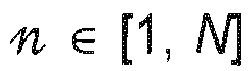


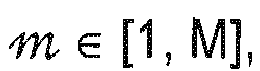


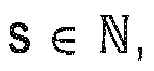



le câble (10) est un câble en quarte avec M = 2 et N = 2, dans lequel les quatre fils (16, 18, 20, 22) des deux lignes sont torsadés en forme de croix les uns avec les autres. - Câble (10) selon la revendication 1,
caractérisé en ce que
le diélectrique (24, 26, 28, 30) des fils (16, 18, 20, 22) d'au moins une ligne est réalisé à partir du matériau polypropylène (PP), et le diélectrique (24, 26, 28, 30) des fils (16, 18, 20, 22) d'au moins une autre ligne est réalisé à partir du matériau polyéthylène (PE). - Câble (10) selon la revendication 1 ou 2,
caractérisé en ce que
le diélectrique (24, 26, 28, 30) des fils (16, 18, 20, 22) d'au moins une ligne est composé d'une structure de couches concentriques de deux ou de plusieurs matériaux diélectriques (70) avec des valeurs différentes pour la permittivité relative ε r. - Câble (10) selon l'une des revendications précédentes,
caractérisé en ce que
dans les fils (16, 18, 20, 22) d'au moins une ligne, un intervalle entre les fils (16, 18, 20, 22) de cette ligne et la gaine extérieure (12) tournée vers les fils (16, 18, 20, 22) de cette ligne est rempli d'un matériau diélectrique (72, 74) qui présente une autre valeur pour la permittivité relative ε r que le diélectrique (24, 26, 28, 30) entourant les fils (16, 18, 20, 22) de cette ligne. - Câble (10) selon l'une des revendications précédentes,
caractérisé en ce que
un revêtement ayant un diélectrique supplémentaire (70, 72, 74) est prévu sur un côté intérieur de la gaine extérieure (12) tourné vers les fils (16, 18, 20, 22) d'une ligne, ledit diélectrique présentant une autre valeur pour la permittivité relative ε r que le diélectrique (24, 26, 28, 30) entourant les fils (16, 18, 20, 22) de cette ligne. - Câble (10) selon la revendication 5,
caractérisé en ce que
le diélectrique supplémentaire est composé comme succession de couches de matériaux diélectriques (70, 72, 74) ayant des valeurs respectivement différentes pour la permittivité relative εr. - Câble (10) selon l'une au moins des revendications précédentes,
caractérisé en ce que
le diélectrique (24, 26, 28, 30) d'au moins un fil (16, 18, 20, 22) est disposé dans un espace entre le fil (16, 18, 20, 22) et la gaine extérieure (12), de telle sorte que cet espace est délimité par les fils voisins (16, 18, 20, 22) en formant un parabole, vu en coupe transversale du câble (10). - Câble (10) selon l'une au moins des revendications précédentes,
caractérisé en ce que
κ ∈ [-u, -w] et κ ∈ [w, u], avec w = 0.01, 0.03, 0.1, 0.2, 0.3, 0.5, 0.7, 0.9, 1.0, 1.2, 1.4 ou 1.6 et u = 0.03, 0.1, 0.2, 0.3, 0.5, 0.7, 0.9, 1.0, 1.2, 1.4, 1.6 ou 1.8 et avec |w| < |u|. - Câble (10) selon l'une au moins des revendications précédentes,
caractérisé en ce que
il est prévu en supplément une gaine de blindage (14) en un matériau électriquement conducteur à l'intérieur de laquelle sont disposées les lignes. - Câble (10) selon la revendication 9,
caractérisé en ce que
la gaine de blindage (14) est disposée radialement à l'extérieur ou à l'intérieur de la gaine extérieure (12). - Câble (10) selon la revendication 9,
caractérisé en ce que
la gaine de blindage (14) est intégrée dans la gaine extérieure (12).
Applications Claiming Priority (2)
| Application Number | Priority Date | Filing Date | Title |
|---|---|---|---|
| DE102016003134.4A DE102016003134A1 (de) | 2016-03-15 | 2016-03-15 | Kabel zum Übertragen von elektrischen Signalen |
| PCT/EP2017/000339 WO2017157521A1 (fr) | 2016-03-15 | 2017-03-15 | Câble de transmission de signaux électriques |
Publications (2)
| Publication Number | Publication Date |
|---|---|
| EP3430633A1 EP3430633A1 (fr) | 2019-01-23 |
| EP3430633B1 true EP3430633B1 (fr) | 2020-01-22 |
Family
ID=58347311
Family Applications (1)
| Application Number | Title | Priority Date | Filing Date |
|---|---|---|---|
| EP17711090.5A Active EP3430633B1 (fr) | 2016-03-15 | 2017-03-15 | Câble de transmission de signaux électriques |
Country Status (8)
| Country | Link |
|---|---|
| US (1) | US10347397B2 (fr) |
| EP (1) | EP3430633B1 (fr) |
| JP (1) | JP2019508858A (fr) |
| KR (1) | KR20180121535A (fr) |
| CN (1) | CN108885925B (fr) |
| DE (1) | DE102016003134A1 (fr) |
| TW (1) | TW201805959A (fr) |
| WO (1) | WO2017157521A1 (fr) |
Cited By (1)
| Publication number | Priority date | Publication date | Assignee | Title |
|---|---|---|---|---|
| DE112020007381B4 (de) | 2020-09-11 | 2026-03-05 | Mitsubishi Electric Corporation | Kabelsignalübertragungssystem |
Families Citing this family (9)
| Publication number | Priority date | Publication date | Assignee | Title |
|---|---|---|---|---|
| IT201800010156A1 (it) * | 2018-11-08 | 2020-05-08 | Prysmian Spa | Cavo di segnalazione ferroviario resistente al fuoco |
| DE102019112926A1 (de) | 2019-05-16 | 2020-11-19 | Friedrich-Alexander-Universität Erlangen-Nürnberg | Multikabel aus Mehrzahl von dielektrischen Wellenleitern |
| US11075488B2 (en) | 2019-11-25 | 2021-07-27 | TE Connectivity Services Gmbh | Impedance control connector with dielectric seperator rib |
| US11146010B2 (en) | 2019-12-09 | 2021-10-12 | TE Connectivity Services Gmbh | Overmolded contact assembly |
| US11011875B1 (en) | 2019-12-10 | 2021-05-18 | TE Connectivity Services Gmbh | Electrical cable braid positioning clip |
| US10978832B1 (en) | 2020-02-07 | 2021-04-13 | TE Connectivity Services Gmbh | Protection member to protect resilient arms of a contact assembly from stubbing |
| US11296464B2 (en) | 2020-02-14 | 2022-04-05 | TE Connectivity Services Gmbh | Impedance control connector |
| US11915839B2 (en) * | 2022-01-26 | 2024-02-27 | Dell Products L.P. | Data communications cable that utilizes multiple dielectric materials associated with different relative permittivities |
| IT202200010544A1 (it) | 2022-05-20 | 2023-11-20 | Prysmian Spa | Data transmission cable |
Family Cites Families (17)
| Publication number | Priority date | Publication date | Assignee | Title |
|---|---|---|---|---|
| GB609558A (en) * | 1945-03-30 | 1948-10-04 | Standard Telephones Cables Ltd | Communication cables and method of making them |
| DE1106385B (de) * | 1955-02-19 | 1961-05-10 | Siemens Ag | Verfahren zur Herstellung von verdrillten Fernmeldekabel-Adergruppen, insbesondere Sternvierern, mit schaumstoffisolierten Adern |
| DE9218768U1 (de) * | 1992-04-28 | 1995-10-26 | Dätwyler AG Kabel und Systeme, Altdorf | Kabel |
| US6169251B1 (en) * | 1997-03-31 | 2001-01-02 | The Whitaker Corporation | Quad cable |
| GB9707300D0 (en) * | 1997-04-10 | 1997-05-28 | Plastic Insulated Cables Ltd | Communications cable |
| JPH1125765A (ja) * | 1997-06-27 | 1999-01-29 | Furukawa Electric Co Ltd:The | 多対ケーブル |
| US6403887B1 (en) * | 1997-12-16 | 2002-06-11 | Tensolite Company | High speed data transmission cable and method of forming same |
| GB9930509D0 (en) * | 1999-12-24 | 2000-02-16 | Plastic Insulated Cables Ltd | Communications cable |
| GB2419225B (en) * | 2003-07-28 | 2007-08-01 | Belden Cdt Networking Inc | Skew adjusted data cable |
| CN1902717B (zh) * | 2003-10-31 | 2010-05-12 | Adc公司 | 偏置填料以及包括所述偏置填料的电缆和电缆组 |
| CN100396165C (zh) * | 2003-11-08 | 2008-06-18 | 鸿富锦精密工业(深圳)有限公司 | 消除高速板串扰的差分线组合方式 |
| US7763802B2 (en) * | 2006-09-13 | 2010-07-27 | Schlumberger Technology Corporation | Electrical cable |
| CN101536119A (zh) * | 2006-11-06 | 2009-09-16 | 纳幕尔杜邦公司 | 周期性地改变传播速度以减少沿电缆长度的添加失真 |
| US8445787B2 (en) * | 2009-05-06 | 2013-05-21 | Panduit Corp. | Communication cable with improved electrical characteristics |
| JP5012854B2 (ja) * | 2009-06-08 | 2012-08-29 | 住友電気工業株式会社 | 平衡ケーブル |
| US8981216B2 (en) * | 2010-06-23 | 2015-03-17 | Tyco Electronics Corporation | Cable assembly for communicating signals over multiple conductors |
| DE202011005273U1 (de) * | 2011-04-14 | 2011-08-23 | Rosenberger Hochfrequenztechnik Gmbh & Co. Kg | Sternvierer-Kabel mit Schirm |
-
2016
- 2016-03-15 DE DE102016003134.4A patent/DE102016003134A1/de not_active Withdrawn
-
2017
- 2017-03-14 TW TW106108350A patent/TW201805959A/zh unknown
- 2017-03-15 WO PCT/EP2017/000339 patent/WO2017157521A1/fr not_active Ceased
- 2017-03-15 CN CN201780017431.0A patent/CN108885925B/zh active Active
- 2017-03-15 KR KR1020187026371A patent/KR20180121535A/ko not_active Withdrawn
- 2017-03-15 EP EP17711090.5A patent/EP3430633B1/fr active Active
- 2017-03-15 JP JP2018548329A patent/JP2019508858A/ja active Pending
- 2017-03-15 US US16/084,478 patent/US10347397B2/en active Active
Non-Patent Citations (1)
| Title |
|---|
| None * |
Cited By (1)
| Publication number | Priority date | Publication date | Assignee | Title |
|---|---|---|---|---|
| DE112020007381B4 (de) | 2020-09-11 | 2026-03-05 | Mitsubishi Electric Corporation | Kabelsignalübertragungssystem |
Also Published As
| Publication number | Publication date |
|---|---|
| EP3430633A1 (fr) | 2019-01-23 |
| US20190080823A1 (en) | 2019-03-14 |
| KR20180121535A (ko) | 2018-11-07 |
| DE102016003134A1 (de) | 2017-09-21 |
| CN108885925A (zh) | 2018-11-23 |
| US10347397B2 (en) | 2019-07-09 |
| CN108885925B (zh) | 2019-11-19 |
| WO2017157521A1 (fr) | 2017-09-21 |
| TW201805959A (zh) | 2018-02-16 |
| JP2019508858A (ja) | 2019-03-28 |
Similar Documents
| Publication | Publication Date | Title |
|---|---|---|
| EP3430633B1 (fr) | Câble de transmission de signaux électriques | |
| DE875054C (de) | Elektrischer Leiter | |
| EP2697804B1 (fr) | Câble à quarte en étoile avec blindage | |
| EP3172741B1 (fr) | Câble de données pour transmissions de données à haut débit | |
| DE112016006142T5 (de) | Kommunikationskabel | |
| EP3132513B1 (fr) | Ensemble de câbles | |
| DE112018000634T5 (de) | Kommunikationskabel | |
| EP0915486B1 (fr) | Câble de transmission de données | |
| DE3008953A1 (de) | Geschuetztes mehradriges kabel | |
| DE102014223119B4 (de) | Datenkabel sowie Verfahren zur Herstellung eines Datenkabels | |
| DE29703112U1 (de) | Datenkabel | |
| WO2021185983A1 (fr) | Câble | |
| EP2989641B1 (fr) | Câble de données à haut débit | |
| EP2697803B1 (fr) | Câble à quarte en étoile comportant un blindage | |
| EP3595099B1 (fr) | Voie veineuse centrale | |
| WO2018228911A1 (fr) | Câble de données pour des zones à risques d'explosion | |
| DE102018103607B4 (de) | Zweidrahtleitung mit verschachtelter Isolierung, sowie Verfahren und Vorrichtung zum Herstellen einer Zweidrahtleitung | |
| DE892007C (de) | Fernmeldekabel mit mehreren ungeschirmren verdrillten Adergruppen für die Mehrfach-Trägerfrequenzubertragung über große Entfernungen | |
| DE102016221661A1 (de) | Kabel, insbesondere Datenkabel | |
| DE2503463A1 (de) | Nachrichtenkabel | |
| DE202011002731U1 (de) | Kabel mit verseilten Leiterpaaren | |
| EP4631072A1 (fr) | Câble de transmission de données et procédé de fabrication d'un câble de transmission de données blindé | |
| DD290737A5 (de) | Hochfrequenz-vielfachleitung | |
| DE2653668A1 (de) | Element eines telefonkabels | |
| DE1101553B (de) | Mehrleiter-Fernmeldekabel und Verfahren zu seiner Herstellung |
Legal Events
| Date | Code | Title | Description |
|---|---|---|---|
| STAA | Information on the status of an ep patent application or granted ep patent |
Free format text: STATUS: UNKNOWN |
|
| STAA | Information on the status of an ep patent application or granted ep patent |
Free format text: STATUS: THE INTERNATIONAL PUBLICATION HAS BEEN MADE |
|
| PUAI | Public reference made under article 153(3) epc to a published international application that has entered the european phase |
Free format text: ORIGINAL CODE: 0009012 |
|
| STAA | Information on the status of an ep patent application or granted ep patent |
Free format text: STATUS: REQUEST FOR EXAMINATION WAS MADE |
|
| 17P | Request for examination filed |
Effective date: 20180917 |
|
| AK | Designated contracting states |
Kind code of ref document: A1 Designated state(s): AL AT BE BG CH CY CZ DE DK EE ES FI FR GB GR HR HU IE IS IT LI LT LU LV MC MK MT NL NO PL PT RO RS SE SI SK SM TR |
|
| AX | Request for extension of the european patent |
Extension state: BA ME |
|
| DAV | Request for validation of the european patent (deleted) | ||
| DAX | Request for extension of the european patent (deleted) | ||
| GRAP | Despatch of communication of intention to grant a patent |
Free format text: ORIGINAL CODE: EPIDOSNIGR1 |
|
| STAA | Information on the status of an ep patent application or granted ep patent |
Free format text: STATUS: GRANT OF PATENT IS INTENDED |
|
| RIC1 | Information provided on ipc code assigned before grant |
Ipc: H01B 7/02 20060101ALI20190827BHEP Ipc: H01B 11/00 20060101AFI20190827BHEP Ipc: H01B 3/30 20060101ALN20190827BHEP |
|
| INTG | Intention to grant announced |
Effective date: 20190911 |
|
| GRAS | Grant fee paid |
Free format text: ORIGINAL CODE: EPIDOSNIGR3 |
|
| GRAA | (expected) grant |
Free format text: ORIGINAL CODE: 0009210 |
|
| STAA | Information on the status of an ep patent application or granted ep patent |
Free format text: STATUS: THE PATENT HAS BEEN GRANTED |
|
| AK | Designated contracting states |
Kind code of ref document: B1 Designated state(s): AL AT BE BG CH CY CZ DE DK EE ES FI FR GB GR HR HU IE IS IT LI LT LU LV MC MK MT NL NO PL PT RO RS SE SI SK SM TR |
|
| REG | Reference to a national code |
Ref country code: GB Ref legal event code: FG4D Free format text: NOT ENGLISH |
|
| REG | Reference to a national code |
Ref country code: CH Ref legal event code: EP |
|
| REG | Reference to a national code |
Ref country code: AT Ref legal event code: REF Ref document number: 1227446 Country of ref document: AT Kind code of ref document: T Effective date: 20200215 |
|
| REG | Reference to a national code |
Ref country code: IE Ref legal event code: FG4D Free format text: LANGUAGE OF EP DOCUMENT: GERMAN |
|
| REG | Reference to a national code |
Ref country code: DE Ref legal event code: R096 Ref document number: 502017003530 Country of ref document: DE |
|
| REG | Reference to a national code |
Ref country code: SE Ref legal event code: TRGR |
|
| REG | Reference to a national code |
Ref country code: NL Ref legal event code: MP Effective date: 20200122 |
|
| REG | Reference to a national code |
Ref country code: LT Ref legal event code: MG4D |
|
| PG25 | Lapsed in a contracting state [announced via postgrant information from national office to epo] |
Ref country code: NL Free format text: LAPSE BECAUSE OF FAILURE TO SUBMIT A TRANSLATION OF THE DESCRIPTION OR TO PAY THE FEE WITHIN THE PRESCRIBED TIME-LIMIT Effective date: 20200122 Ref country code: RS Free format text: LAPSE BECAUSE OF FAILURE TO SUBMIT A TRANSLATION OF THE DESCRIPTION OR TO PAY THE FEE WITHIN THE PRESCRIBED TIME-LIMIT Effective date: 20200122 Ref country code: PT Free format text: LAPSE BECAUSE OF FAILURE TO SUBMIT A TRANSLATION OF THE DESCRIPTION OR TO PAY THE FEE WITHIN THE PRESCRIBED TIME-LIMIT Effective date: 20200614 Ref country code: NO Free format text: LAPSE BECAUSE OF FAILURE TO SUBMIT A TRANSLATION OF THE DESCRIPTION OR TO PAY THE FEE WITHIN THE PRESCRIBED TIME-LIMIT Effective date: 20200422 Ref country code: FI Free format text: LAPSE BECAUSE OF FAILURE TO SUBMIT A TRANSLATION OF THE DESCRIPTION OR TO PAY THE FEE WITHIN THE PRESCRIBED TIME-LIMIT Effective date: 20200122 |
|
| PG25 | Lapsed in a contracting state [announced via postgrant information from national office to epo] |
Ref country code: BG Free format text: LAPSE BECAUSE OF FAILURE TO SUBMIT A TRANSLATION OF THE DESCRIPTION OR TO PAY THE FEE WITHIN THE PRESCRIBED TIME-LIMIT Effective date: 20200422 Ref country code: IS Free format text: LAPSE BECAUSE OF FAILURE TO SUBMIT A TRANSLATION OF THE DESCRIPTION OR TO PAY THE FEE WITHIN THE PRESCRIBED TIME-LIMIT Effective date: 20200522 Ref country code: LV Free format text: LAPSE BECAUSE OF FAILURE TO SUBMIT A TRANSLATION OF THE DESCRIPTION OR TO PAY THE FEE WITHIN THE PRESCRIBED TIME-LIMIT Effective date: 20200122 Ref country code: HR Free format text: LAPSE BECAUSE OF FAILURE TO SUBMIT A TRANSLATION OF THE DESCRIPTION OR TO PAY THE FEE WITHIN THE PRESCRIBED TIME-LIMIT Effective date: 20200122 Ref country code: GR Free format text: LAPSE BECAUSE OF FAILURE TO SUBMIT A TRANSLATION OF THE DESCRIPTION OR TO PAY THE FEE WITHIN THE PRESCRIBED TIME-LIMIT Effective date: 20200423 |
|
| REG | Reference to a national code |
Ref country code: DE Ref legal event code: R097 Ref document number: 502017003530 Country of ref document: DE |
|
| PG25 | Lapsed in a contracting state [announced via postgrant information from national office to epo] |
Ref country code: SM Free format text: LAPSE BECAUSE OF FAILURE TO SUBMIT A TRANSLATION OF THE DESCRIPTION OR TO PAY THE FEE WITHIN THE PRESCRIBED TIME-LIMIT Effective date: 20200122 Ref country code: EE Free format text: LAPSE BECAUSE OF FAILURE TO SUBMIT A TRANSLATION OF THE DESCRIPTION OR TO PAY THE FEE WITHIN THE PRESCRIBED TIME-LIMIT Effective date: 20200122 Ref country code: SK Free format text: LAPSE BECAUSE OF FAILURE TO SUBMIT A TRANSLATION OF THE DESCRIPTION OR TO PAY THE FEE WITHIN THE PRESCRIBED TIME-LIMIT Effective date: 20200122 Ref country code: DK Free format text: LAPSE BECAUSE OF FAILURE TO SUBMIT A TRANSLATION OF THE DESCRIPTION OR TO PAY THE FEE WITHIN THE PRESCRIBED TIME-LIMIT Effective date: 20200122 Ref country code: MC Free format text: LAPSE BECAUSE OF FAILURE TO SUBMIT A TRANSLATION OF THE DESCRIPTION OR TO PAY THE FEE WITHIN THE PRESCRIBED TIME-LIMIT Effective date: 20200122 Ref country code: RO Free format text: LAPSE BECAUSE OF FAILURE TO SUBMIT A TRANSLATION OF THE DESCRIPTION OR TO PAY THE FEE WITHIN THE PRESCRIBED TIME-LIMIT Effective date: 20200122 Ref country code: ES Free format text: LAPSE BECAUSE OF FAILURE TO SUBMIT A TRANSLATION OF THE DESCRIPTION OR TO PAY THE FEE WITHIN THE PRESCRIBED TIME-LIMIT Effective date: 20200122 Ref country code: CZ Free format text: LAPSE BECAUSE OF FAILURE TO SUBMIT A TRANSLATION OF THE DESCRIPTION OR TO PAY THE FEE WITHIN THE PRESCRIBED TIME-LIMIT Effective date: 20200122 Ref country code: LT Free format text: LAPSE BECAUSE OF FAILURE TO SUBMIT A TRANSLATION OF THE DESCRIPTION OR TO PAY THE FEE WITHIN THE PRESCRIBED TIME-LIMIT Effective date: 20200122 |
|
| REG | Reference to a national code |
Ref country code: CH Ref legal event code: PL |
|
| PLBE | No opposition filed within time limit |
Free format text: ORIGINAL CODE: 0009261 |
|
| STAA | Information on the status of an ep patent application or granted ep patent |
Free format text: STATUS: NO OPPOSITION FILED WITHIN TIME LIMIT |
|
| REG | Reference to a national code |
Ref country code: BE Ref legal event code: MM Effective date: 20200331 |
|
| 26N | No opposition filed |
Effective date: 20201023 |
|
| PG25 | Lapsed in a contracting state [announced via postgrant information from national office to epo] |
Ref country code: LU Free format text: LAPSE BECAUSE OF NON-PAYMENT OF DUE FEES Effective date: 20200315 |
|
| PG25 | Lapsed in a contracting state [announced via postgrant information from national office to epo] |
Ref country code: IE Free format text: LAPSE BECAUSE OF NON-PAYMENT OF DUE FEES Effective date: 20200315 Ref country code: CH Free format text: LAPSE BECAUSE OF NON-PAYMENT OF DUE FEES Effective date: 20200331 Ref country code: LI Free format text: LAPSE BECAUSE OF NON-PAYMENT OF DUE FEES Effective date: 20200331 |
|
| PG25 | Lapsed in a contracting state [announced via postgrant information from national office to epo] |
Ref country code: SI Free format text: LAPSE BECAUSE OF FAILURE TO SUBMIT A TRANSLATION OF THE DESCRIPTION OR TO PAY THE FEE WITHIN THE PRESCRIBED TIME-LIMIT Effective date: 20200122 Ref country code: PL Free format text: LAPSE BECAUSE OF FAILURE TO SUBMIT A TRANSLATION OF THE DESCRIPTION OR TO PAY THE FEE WITHIN THE PRESCRIBED TIME-LIMIT Effective date: 20200122 Ref country code: BE Free format text: LAPSE BECAUSE OF NON-PAYMENT OF DUE FEES Effective date: 20200331 |
|
| PG25 | Lapsed in a contracting state [announced via postgrant information from national office to epo] |
Ref country code: TR Free format text: LAPSE BECAUSE OF FAILURE TO SUBMIT A TRANSLATION OF THE DESCRIPTION OR TO PAY THE FEE WITHIN THE PRESCRIBED TIME-LIMIT Effective date: 20200122 Ref country code: MT Free format text: LAPSE BECAUSE OF FAILURE TO SUBMIT A TRANSLATION OF THE DESCRIPTION OR TO PAY THE FEE WITHIN THE PRESCRIBED TIME-LIMIT Effective date: 20200122 Ref country code: CY Free format text: LAPSE BECAUSE OF FAILURE TO SUBMIT A TRANSLATION OF THE DESCRIPTION OR TO PAY THE FEE WITHIN THE PRESCRIBED TIME-LIMIT Effective date: 20200122 |
|
| PG25 | Lapsed in a contracting state [announced via postgrant information from national office to epo] |
Ref country code: MK Free format text: LAPSE BECAUSE OF FAILURE TO SUBMIT A TRANSLATION OF THE DESCRIPTION OR TO PAY THE FEE WITHIN THE PRESCRIBED TIME-LIMIT Effective date: 20200122 Ref country code: AL Free format text: LAPSE BECAUSE OF FAILURE TO SUBMIT A TRANSLATION OF THE DESCRIPTION OR TO PAY THE FEE WITHIN THE PRESCRIBED TIME-LIMIT Effective date: 20200122 |
|
| REG | Reference to a national code |
Ref country code: AT Ref legal event code: MM01 Ref document number: 1227446 Country of ref document: AT Kind code of ref document: T Effective date: 20220315 |
|
| P01 | Opt-out of the competence of the unified patent court (upc) registered |
Effective date: 20230527 |
|
| PG25 | Lapsed in a contracting state [announced via postgrant information from national office to epo] |
Ref country code: AT Free format text: LAPSE BECAUSE OF NON-PAYMENT OF DUE FEES Effective date: 20220315 |
|
| REG | Reference to a national code |
Ref country code: DE Ref legal event code: R082 Ref document number: 502017003530 Country of ref document: DE Representative=s name: KANDLBINDER, MARKUS, DIPL.-PHYS., DE |
|
| PGFP | Annual fee paid to national office [announced via postgrant information from national office to epo] |
Ref country code: SE Payment date: 20260323 Year of fee payment: 10 |
|
| PGFP | Annual fee paid to national office [announced via postgrant information from national office to epo] |
Ref country code: GB Payment date: 20260304 Year of fee payment: 10 |
|
| PGFP | Annual fee paid to national office [announced via postgrant information from national office to epo] |
Ref country code: DE Payment date: 20260320 Year of fee payment: 10 |
|
| PGFP | Annual fee paid to national office [announced via postgrant information from national office to epo] |
Ref country code: IT Payment date: 20260320 Year of fee payment: 10 |
|
| PGFP | Annual fee paid to national office [announced via postgrant information from national office to epo] |
Ref country code: FR Payment date: 20260323 Year of fee payment: 10 |