EP3430934A1 - Semelle auxétique dotée d'un câblage de tige - Google Patents
Semelle auxétique dotée d'un câblage de tige Download PDFInfo
- Publication number
- EP3430934A1 EP3430934A1 EP18193707.9A EP18193707A EP3430934A1 EP 3430934 A1 EP3430934 A1 EP 3430934A1 EP 18193707 A EP18193707 A EP 18193707A EP 3430934 A1 EP3430934 A1 EP 3430934A1
- Authority
- EP
- European Patent Office
- Prior art keywords
- footwear
- auxetic
- portions
- base layer
- article
- Prior art date
- Legal status (The legal status is an assumption and is not a legal conclusion. Google has not performed a legal analysis and makes no representation as to the accuracy of the status listed.)
- Granted
Links
Images












Classifications
-
- A—HUMAN NECESSITIES
- A43—FOOTWEAR
- A43B—CHARACTERISTIC FEATURES OF FOOTWEAR; PARTS OF FOOTWEAR
- A43B13/00—Soles; Sole-and-heel integral units
- A43B13/14—Soles; Sole-and-heel integral units characterised by the constructive form
- A43B13/18—Resilient soles
- A43B13/181—Resiliency achieved by the structure of the sole
-
- A—HUMAN NECESSITIES
- A43—FOOTWEAR
- A43B—CHARACTERISTIC FEATURES OF FOOTWEAR; PARTS OF FOOTWEAR
- A43B13/00—Soles; Sole-and-heel integral units
- A43B13/14—Soles; Sole-and-heel integral units characterised by the constructive form
-
- A—HUMAN NECESSITIES
- A43—FOOTWEAR
- A43B—CHARACTERISTIC FEATURES OF FOOTWEAR; PARTS OF FOOTWEAR
- A43B13/00—Soles; Sole-and-heel integral units
- A43B13/14—Soles; Sole-and-heel integral units characterised by the constructive form
- A43B13/18—Resilient soles
- A43B13/187—Resiliency achieved by the features of the material, e.g. foam, non liquid materials
-
- A—HUMAN NECESSITIES
- A43—FOOTWEAR
- A43B—CHARACTERISTIC FEATURES OF FOOTWEAR; PARTS OF FOOTWEAR
- A43B13/00—Soles; Sole-and-heel integral units
- A43B13/28—Soles; Sole-and-heel integral units characterised by their attachment, also attachment of combined soles and heels
-
- A—HUMAN NECESSITIES
- A43—FOOTWEAR
- A43B—CHARACTERISTIC FEATURES OF FOOTWEAR; PARTS OF FOOTWEAR
- A43B23/00—Uppers; Boot legs; Stiffeners; Other single parts of footwear
- A43B23/02—Uppers; Boot legs
- A43B23/0245—Uppers; Boot legs characterised by the constructive form
-
- A—HUMAN NECESSITIES
- A43—FOOTWEAR
- A43B—CHARACTERISTIC FEATURES OF FOOTWEAR; PARTS OF FOOTWEAR
- A43B23/00—Uppers; Boot legs; Stiffeners; Other single parts of footwear
- A43B23/02—Uppers; Boot legs
- A43B23/0245—Uppers; Boot legs characterised by the constructive form
- A43B23/0265—Uppers; Boot legs characterised by the constructive form having different properties in different directions
-
- A—HUMAN NECESSITIES
- A43—FOOTWEAR
- A43B—CHARACTERISTIC FEATURES OF FOOTWEAR; PARTS OF FOOTWEAR
- A43B5/00—Footwear for sporting purposes
- A43B5/06—Running shoes; Track shoes
-
- A—HUMAN NECESSITIES
- A43—FOOTWEAR
- A43C—FASTENINGS OR ATTACHMENTS OF FOOTWEAR; LACES IN GENERAL
- A43C1/00—Shoe lacing fastenings
- A43C1/003—Zone lacing, i.e. whereby different zones of the footwear have different lacing tightening degrees, using one or a plurality of laces
-
- B—PERFORMING OPERATIONS; TRANSPORTING
- B29—WORKING OF PLASTICS; WORKING OF SUBSTANCES IN A PLASTIC STATE IN GENERAL
- B29C—SHAPING OR JOINING OF PLASTICS; SHAPING OF MATERIAL IN A PLASTIC STATE, NOT OTHERWISE PROVIDED FOR; AFTER-TREATMENT OF THE SHAPED PRODUCTS, e.g. REPAIRING
- B29C44/00—Shaping by internal pressure generated in the material, e.g. swelling or foaming ; Producing porous or cellular expanded plastics articles
- B29C44/34—Auxiliary operations
- B29C44/35—Component parts; Details or accessories
- B29C44/355—Characteristics of the foam, e.g. having particular surface properties or structure
- B29C44/357—Auxetic foams, i.e. material with negative Poisson ratio; anti rubber; dilatational; re-entrant
-
- B—PERFORMING OPERATIONS; TRANSPORTING
- B29—WORKING OF PLASTICS; WORKING OF SUBSTANCES IN A PLASTIC STATE IN GENERAL
- B29C—SHAPING OR JOINING OF PLASTICS; SHAPING OF MATERIAL IN A PLASTIC STATE, NOT OTHERWISE PROVIDED FOR; AFTER-TREATMENT OF THE SHAPED PRODUCTS, e.g. REPAIRING
- B29C44/00—Shaping by internal pressure generated in the material, e.g. swelling or foaming ; Producing porous or cellular expanded plastics articles
- B29C44/34—Auxiliary operations
- B29C44/56—After-treatment of articles, e.g. for altering the shape
-
- A—HUMAN NECESSITIES
- A43—FOOTWEAR
- A43B—CHARACTERISTIC FEATURES OF FOOTWEAR; PARTS OF FOOTWEAR
- A43B13/00—Soles; Sole-and-heel integral units
- A43B13/14—Soles; Sole-and-heel integral units characterised by the constructive form
- A43B13/18—Resilient soles
-
- B—PERFORMING OPERATIONS; TRANSPORTING
- B29—WORKING OF PLASTICS; WORKING OF SUBSTANCES IN A PLASTIC STATE IN GENERAL
- B29K—INDEXING SCHEME ASSOCIATED WITH SUBCLASSES B29B, B29C OR B29D, RELATING TO MOULDING MATERIALS OR TO MATERIALS FOR MOULDS, REINFORCEMENTS, FILLERS OR PREFORMED PARTS, e.g. INSERTS
- B29K2075/00—Use of PU, i.e. polyureas or polyurethanes or derivatives thereof, as moulding material
-
- B—PERFORMING OPERATIONS; TRANSPORTING
- B29—WORKING OF PLASTICS; WORKING OF SUBSTANCES IN A PLASTIC STATE IN GENERAL
- B29K—INDEXING SCHEME ASSOCIATED WITH SUBCLASSES B29B, B29C OR B29D, RELATING TO MOULDING MATERIALS OR TO MATERIALS FOR MOULDS, REINFORCEMENTS, FILLERS OR PREFORMED PARTS, e.g. INSERTS
- B29K2223/00—Use of polyalkenes or derivatives thereof as reinforcement
- B29K2223/04—Polymers of ethylene
- B29K2223/08—Use of copolymers of ethylene as reinforcement
- B29K2223/083—EVA, i.e. ethylene vinyl acetate copolymer
-
- B—PERFORMING OPERATIONS; TRANSPORTING
- B29—WORKING OF PLASTICS; WORKING OF SUBSTANCES IN A PLASTIC STATE IN GENERAL
- B29L—INDEXING SCHEME ASSOCIATED WITH SUBCLASS B29C, RELATING TO PARTICULAR ARTICLES
- B29L2031/00—Other particular articles
- B29L2031/48—Wearing apparel
- B29L2031/50—Footwear, e.g. shoes or parts thereof
- B29L2031/504—Soles
Definitions
- Articles of footwear generally include two primary elements: an upper and a sole structure.
- the upper is often formed from a plurality of material elements (e.g., textiles, polymer sheet layers, foam layers, leather, synthetic leather) that are stitched or adhesively bonded together to form a void on the interior of the footwear for comfortably and securely receiving a foot. More particularly, the upper forms a structure that extends over instep and toe areas of the foot, along medial and lateral sides of the foot, and around a heel area of the foot. This plurality of material elements may form a base layer of the upper.
- the upper may also incorporate a lacing system to adjust fit of the footwear, as well as permitting entry and removal of the foot from the void within the upper.
- the upper may include a tongue that extends under the lacing system to enhance adjustability and comfort of the footwear, and the upper may incorporate a heel counter.
- the various material elements forming the upper impart different properties to different areas of the upper.
- textile elements may provide breathability and may absorb moisture from the foot, foam layers may compress to impart comfort, and leather may impart durability and wear-resistance.
- the overall mass of the footwear may increase proportionally.
- the time and expense associated with transporting, stocking, cutting, and joining the material elements may also increase.
- waste material from cutting and stitching processes may accumulate to a greater degree as the number of material elements incorporated into an upper increases.
- products with a greater number of material elements may be more difficult to recycle than products formed from fewer material elements. By decreasing the number of material elements, therefore, the mass of the footwear and waste may be decreased, while increasing manufacturing efficiency and recyclability.
- the sole structure is secured to a lower portion of the upper so as to be positioned between the foot and the ground.
- the sole structure often includes a midsole and an outsole.
- the midsole may be formed from a polymer foam material that attenuates ground reaction forces (i.e., provides cushioning) during walking, running, and other ambulatory activities.
- the midsole may also include fluid-filled chambers, plates, moderators, or other elements that further attenuate forces, enhance stability, or influence the motions of the foot, for example.
- the outsole forms a ground-contacting element of the footwear and is usually fashioned from a durable and wear-resistant rubber material that includes texturing to impart traction.
- the sole structure may also include a sockliner positioned within the upper and proximal a lower surface of the foot to enhance footwear comfort.
- the midsole, or the outsole, or both may be formed to have an auxetic structure.
- auxetic elements incorporated within sole structures may permit the footwear to dynamically adjust its fit upon a wearer's foot in response to specific forces placed upon it, such as forces due to walking, running, athletic activity, or other typical uses of the footwear.
- one or more tensile strands separate from the material or materials of the base layer may be incorporated into the upper.
- the additional incorporation of tensile strands in the upper of the footwear may advantageously permit localized tuning of the dynamic adjustment of fit imparted by the auxetic element.
- an article of footwear includes an upper and a sole structure.
- the upper comprises a base layer and a tensile strand, the tensile strand having a first end and a second end. A portion of the tensile strand between the first end and the second end is separate from the material of the base layer and lies adjacent to a surface of the base layer.
- the sole structure comprises an auxetic element with a plurality of apertures extending therethrough. The first end of the tensile strand has a fixed position relative to a peripheral region of the auxetic element.
- an article of footwear in another aspect, includes a sole structure, a base layer, and a tensile strand.
- the sole structure includes an auxetic sole portion oriented along a plane. The plane extends in a first direction between a heel region and a forefoot region of the article of footwear, and extends in a second direction between a medial side and a lateral side of the article of footwear.
- the auxetic sole portion has a plurality of apertures operable to change shape in response to either a tension or a compression applied to the auxetic sole portion along the plane.
- the base layer is secured to a peripheral region of the sole structure.
- the tensile strand is separate from the material of the base layer and has at least one end fixed in position relative to a peripheral region of the base layer.
- an article of footwear in another aspect, includes a base layer, an auxetic sole element, and a plurality of tensile strands.
- the auxetic sole element extends along both a first direction and an orthogonal second direction of a plane, and comprises a plurality of first portions joined to each other by a plurality of second portions.
- Each of the plurality of tensile strands lies adjacent to a surface of the base layer, and at least one end of each of the plurality of tensile strands has a fixed position relative to a peripheral region of the auxetic sole element.
- a tension applied to the auxetic sole element in either the first direction or the second direction induces the first portions to rotate relative to one another and induces the auxetic sole element to expand in both the first direction and the second direction.
- the following discussion and accompanying figures disclose articles of footwear having uppers that include tensile strands and sole structures that include auxetic elements.
- the article of footwear is disclosed as having a general configuration suitable for walking or running.
- Concepts associated with the footwear, including the upper may also be applied to a variety of other athletic footwear types, including baseball shoes, basketball shoes, cross-training shoes, cycling shoes, football shoes, tennis shoes, soccer shoes, and hiking boots, for example.
- the concepts may also be applied to footwear types that are generally considered to be non-athletic, including dress shoes, loafers, sandals, and work boots.
- the concepts disclosed herein apply, therefore, to a wide variety of footwear types.
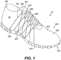
- FIGS. 1-8 An article of footwear 10 is depicted in FIGS. 1-8 as including an upper 200 and a sole structure 300.
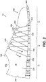
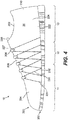
- footwear 10 may be divided into three general regions: a forefoot region 11, a midfoot region 12, and a heel region 13, as shown in FIGS. 2 and 4 .
- Forefoot region 11 generally includes portions of footwear 10 corresponding with the toes and the joints connecting the metatarsals with the phalanges.
- Midfoot region 12 generally includes portions of footwear 10 corresponding with the arch area of the foot.
- Heel region 13 generally includes portions of footwear 10 corresponding with rear portions of the foot, including the calcaneus bone.
- Footwear 10 also includes a medial side 14 and a lateral side 15. Medial side 14 and lateral side 15 and extend through each of forefoot region 11, midfoot region 12, and heel region 13 and correspond with opposite sides of footwear 10.
- Forefoot region 11, midfoot region 12, heel region 13, medial side 14, and lateral side 15 are not intended to demarcate precise areas of footwear 10. Rather, they are intended to represent general areas of footwear 10 to aid in the following discussion. In addition to being applied to footwear 10, forefoot region 11, midfoot region 12, heel region 13, medial side 14, and lateral side 15 may also be applied to upper 200, sole structure 300, and individual elements thereof.
- the primary elements of upper 200 are a base layer 210 and a plurality of tensile strands 230.
- Base layer 210 may be formed from one or more of a plurality of material elements (e.g., textiles, polymer sheets, foam layers, leather, synthetic leather) that are stitched or bonded together to form a void within footwear 10 for receiving and securing a foot of a wearer relative to sole structure 300.
- the void is shaped to accommodate the foot and extends along the lateral side of the foot, along the medial side of the foot, over the foot, around the heel, and under the foot.
- a lace 204 extends through various lace apertures 227 in base layer 210 and permits the wearer to modify dimensions of upper 200 to accommodate the proportions of the foot. More particularly, lace 204 permits the wearer to tighten upper 200 around the foot, and lace 204 permits the wearer to loosen upper 200 to facilitate entry and removal of the foot from the void (i.e., through ankle opening 202).
- upper 200 includes a tongue 208 that extends between the interior void and lace 204 to enhance the comfort of footwear 10.
- upper 200 may include other lace-receiving elements, such as loops, eyelets, and D-rings.
- upper 200 may incorporate a heel counter that limits heel movement in heel region 13 or a wear-resistant toe guard located in forefoot region 11.
- Both medial side 14 and lateral side 15 and of upper 200 are depicted as incorporating various tensile strands 230 having first ends 231, second ends 232, and middle portions 233 extending between first ends 231 and second ends 232.
- each of medial side 14 and lateral side 15 may include any number of tensile strands 230.
- either medial side 14 or lateral side 15 may not include any tensile strands 230.
- the number of tensile strands 230 incorporated into footwear 10 may accordingly vary significantly.
- tensile strands may have at least a minimal length thereby ensuring that the tensile strands provide support between (or through) two or more distinct regions of an article.
- middle portions 233 of tensile strands 230 have lengths of at least 3 cm, and tensile strands 230 accordingly extend over distances of at least 3 cm.
- middle portions 233 may have lengths of at least 5 cm or at least 10 cm, and tensile strands 230 may extend over distances of at least 5 cm or at least 10 cm, respectively.
- first ends 231 and second ends 232 are depicted as being positioned at different locations spaced from each other by a distance of between 1 cm and 5 cm, first ends 231 and second ends 232 of at least some of tensile strands 230 may be spaced from each other by distances less than 1 cm, or distances greater than 5 cm.
- the material of tensile strands 230 is separate from the material of base layer 210. Moreover, while tensile strands 230 are secured to footwear 10 at first ends 231 and second ends 232, and while middle portions 233 lie adjacent to an outer surface 211 of base layer 210, part or all of middle portions 233 may be unattached to or unbonded to base layer 210 in some configurations of footwear 10. That is, part or all of middle portions 233 may be unsecured to base layer 210 and may accordingly be free to move relative to base layer 210.
- Tensile strands 230 of footwear 10 generally extend between a central region or lace aperture region 226 of base layer 210 (i.e., the region where lace apertures 227 or other lace-receiving elements are located) and a peripheral region 222 of the base layer (i.e., the region at which upper 200 joins with sole structure 300). More particularly, tensile strands 230 extend from lace aperture region 226 to peripheral region 222 of base layer 210, or to peripheral region 322 of sole structure 300, or both.
- Base layer 210 may additionally have a middle region 224 extending between peripheral region 222 and lace aperture region 226.
- FIGS. 1-4 show each of tensile strands 230 as extending between peripheral region 322 of sole structure 300 and an area proximal to a lace aperture 227 in lace aperture region 226.
- First ends 231 and second ends 232 of tensile strands 230 are secured in fixed positions relative to peripheral region 322 of sole structure 300, and middle portions 233 of tensile strands 230 extend around lace apertures 227.
- first ends 231 and second ends 232 may be secured directly to peripheral region 322 of sole structure 300, such as by being adhesively bonded or physically coupled to peripheral region 322.
- at least some of first ends 231 and second ends 232 may be secured indirectly to peripheral region 322 of sole structure 300.
- first ends 231 and second ends 232 may be secured directly to peripheral region 222 of base layer 210, and peripheral region 222 may in turn be directly secured to peripheral region 322 of sole structure 300.
- first ends 231 and second ends 232 may still be secured to have a fixed position relative to peripheral region 322.
- first ends 231 and second ends 232 may be bonded to or otherwise secured to both peripheral region 222 of base layer 210 and peripheral region 322 of sole structure 300.
- first ends 231 and second ends 232 may be either secured either directly or indirectly to peripheral region 222, or peripheral region 322, or both, and may thus be fixed in position relative to either peripheral region 222, or peripheral region 322, or both.
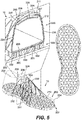
- Peripheral region 222 of upper 200 is depicted in FIG. 5 as being secured to peripheral region 322 of sole structure 300.
- the primary elements of sole structure 300 are a sockliner 206 and an auxetic element 330.
- Sockliner 206 is located within upper 200 and is positioned to extend under a lower surface of the foot.
- Auxetic element 330 extends between the foot and the ground when footwear 10 is worn, and is depicted as forming a ground-contacting surface of footwear 10. Accordingly, in some embodiments, auxetic element 330 may form an outsole element of footwear 10.
- auxetic element 330 has a first surface 331, which is secured to a lower part of outer surface 211 of upper 200, and a second surface 332 which forms a ground-contacting surface of footwear 10.
- First surface 331 may accordingly be an upper surface of auxetic element 330
- second surface 332 may be a lower surface of auxetic element 330.
- a peripheral region 342 of auxetic element 330 extends to a peripheral region 322 of sole structure 300, while a central region 346 of auxetic element 330 is positioned at a central region 326 of sole structure 300.
- auxetic element 330 is depicted in FIGS. 1-8 as spanning an entirety of a horizontal extent of sole structure 300, from forefoot region 11 to heel region 13, and from medial side 14 to lateral side 15.
- auxetic element 330 has a plurality of first portions 351, a plurality of second portions 352 joining first portions 351, and apertures 360 surrounded by first portions 351 and second portions 352.
- Apertures 360 extend from first surface 331 to second surface 332, and completely through auxetic element 330 in a vertical direction.
- First portions 351, second portions 352, and apertures 360 advantageously provide auxetic element 330 with an auxetic structure.
- auxetic structure generally refers to a structure that, when it is placed under tension in a first direction, increases its dimensions in a direction that is orthogonal to the first direction.
- auxetic structures may be characterized as having a negative Poisson's ratio.
- Such structures will generally have at least a monotonic relationship between the applied tension and the increase in the dimension orthogonal to the direction of the tension, that relationship need not be proportional or linear, and in general need only increase in response to increased tension.
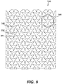
- FIG. 9 depicts an alternate configuration of auxetic element 330, separate from footwear 10.
- the structural features of auxetic element 330 include: first portions 351 of the material of auxetic element 330, which have polygonal shapes, or more specifically triangular shapes; second portions 352 of the material of auxetic element 330, which join adjacent first portions 351; and apertures 360 between first portions 351 and second portions 352, which have polygonal shapes, or more specifically shapes of re-entrant triangles, or three-pointed stars.
- First portions 351, second portions 352, and apertures 360 are arranged in a regular geometric pattern. More specifically, first portions 351, second portions 352, and apertures 360 are arranged in a regular hexagonal tessellation. As a result, the pattern of the structure of auxetic element 330 may be reduced to a pattern contained within one hexagon laid adjacent to itself repeatedly.
- hexagon 380 surrounds a part of auxetic element 330 which, if laid adjacent to itself repeatedly, would produce the pattern of auxetic element 330 as a whole.
- Hexagon 380 may accordingly be considered a unit of the regular hexagonal tessellation of auxetic element 330.
- hexagon 380 contains an alternating sequence of six first portions 351 and six second portions 352 that surround and define the boundary of one aperture 360.
- a person of ordinary skill in the art will recognize that other hexagonal parts of auxetic element 330 could be similarly repeated to produce the pattern of auxetic element 330 as a whole.
- auxetic element 330 Due to the structure of first portions 351, second portions 352, and apertures 360, auxetic element 330 has advantageous properties in response to forces applied to it.
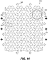
- FIG. 10 shows auxetic element 330 under application of a tension 511 being applied in a first direction (depicted using solid, closed arrows).
- auxetic element 330 exhibits an expansion 521 in the first direction (depicted using open arrows).
- auxetic element 330 also exhibits an expansion 522 in a second direction orthogonal to the first direction (also depicted using open arrows).
- auxetic element 330 when auxetic element 330 is pulled outward in one direction, it expands outward in both that direction and another, perpendicular direction.
- first direction is depicted as being between the left-hand and right-hand sides of the figure, other first directions could be between any two opposite points on auxetic element 330.
- second direction is depicted as being between the top and bottom of the figure, second directions could be orthogonal to other first directions.
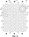
- FIG. 11 similarly depicts the application of a tension 512 in the second direction to auxetic element 330.
- Tension 512 is being applied in a direction orthogonal (or perpendicular) to the direction of tension 511 in FIG. 10 .
- auxetic element 330 responds to tension 512 by exhibiting not only an expansion 522 in the second direction, but also an expansion 521 in the first direction.
- a tension applied to auxetic element 330 in one direction induces auxetic element 330 to expand outward in both that direction and another, perpendicular direction.
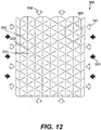
- FIGS. 12 and 13 depict the complementary behavior of auxetic element 330 under an applied compression (i.e., an inwardly-directed or "pushing" force).
- an applied compression i.e., an inwardly-directed or "pushing" force.
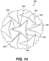
- FIG. 14 upon application of a compression 531 in the first direction (depicted using solid, closed arrows), auxetic element 330 exhibits both a contraction 541 in the first direction and a contraction 542 in the second direction (depicted using open arrows).
- auxetic element 330 upon application of a compression 532 in the second direction, exhibits both contraction 541 in the first direction and contraction 542 in the second direction.
- auxetic element when auxetic element is compressed in one direction, it contracts inward in both that direction and another, perpendicular direction.
- first direction is depicted as being between the left-hand and right-hand sides and the second direction is depicted as being between the top and bottom, other first directions could be between any two opposite points on auxetic element 330, and second directions could be orthogonal to any other first directions.
- FIGS. 14 and 15 depict a portion of auxetic element 330 in greater detail.
- the depicted portion of auxetic element 330 includes six first portions 351 and six second portions 352 surrounding and defining an aperture 360 (as well as parts of the surrounding first portions 351, second portions 352, and apertures 360).
- the reentrant triangular shapes of apertures 360 have three sides 361, which define three inwardly-pointing vertices 362 associated with three outwardly-opening or reentrant angles 363.
- the reentrant triangular shapes of apertures 360 also have three outwardly-pointing vertices or points 364 associated with three inwardly-opening angles 365.
- each aperture 360 accordingly has a central portion 366 between three inwardly-pointing vertices 362, and three radial portions 367 between points 364 and inwardly-pointing vertices 362.
- Apertures 360 are accordingly six-sided polygons, having three outwardly-opening angles (on the "sides” of their reentrant-triangle shapes) and three inwardly-opening angles (on the "points" of their reentrant-triangle shapes).
- the three sides 361 of the reentrant triangles of apertures 360 have reentrant angles 363 of between about 100 degrees and about 170 degrees when auxetic element 330 is not under tension (as depicted in FIGS. 14 and 15 ).
- Each first portion 351 has a center 353 located at a central point of their triangular shapes, and each second portion 352 joins two first portions 351.
- the sides of the triangular shapes of first portions 351 correspond to segments of first portions 351 between adjacent second portions 352.
- each second portion 352 is connected to its nearest neighboring second portions 352 by segments of the two first portions 351 that it joins.
- Each second portion 352 accordingly has four nearest second portions 352 to which it is connected by sides of the two first portions 351 that it joins (at least at portions of auxetic element 330 spaced inward from its edges).
- Auxetic element 330 thus contains a network of second portions 352 which are connected to each other by segments of first portions 351 that correspond to sides of the triangular shapes of first portions 351. Any two second portions 352 spaced apart from each other within auxetic element 330 are connected by a path between them comprising sides of first portions 351.
- FIG. 15 depicts an exemplary path 370 comprising segments 371, which are at angles 372 with respect to each other.
- auxetic element 330 Due to the structure of auxetic element 330, first portions 351 are operable to rotate in response to an applied force. At the same time, due to the structure of auxetic element 330, apertures 360 are correspondingly operable to change shape in response to an applied force.
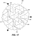
- FIGS. 16 and 17 the portion of auxetic element 330 depicted in FIGS. 14 and 15 is shown under application of an outwardly-directed "pulling" force or tension 510. Under tension 510, first portions 351 rotate around their centers 353. More particularly, as shown in FIG. 16 , any two nearest-neighboring first portions 351 within auxetic element 330 (i.e. two first portions 351 joined by a second portion 352) rotate around their centers 353 in opposite directions, one in a clockwise direction, and the other in a counter-clockwise direction.
- any two nearest-neighboring first portions 351 rotate in opposite directions around the second portion 352 that joins them (again, one in a clockwise direction, and the other in a counter-clockwise direction).
- outwardly-opening angles 363 and inwardly-opening angles 365 increase in magnitude
- central portion 366 and radial portions 367 increase in area
- aperture 360 increases in area and changes shape.
- FIG. 17 also depicts exemplary path 370 as being made more straight under the application of tension 510.
- Angles 372 between segments 371 increase in magnitude, and accordingly, for non-neighboring second portions 352 connected by path 370, a distance between those second portions 352 also increases.
- the application of a tension between two second portions 352 may thus straighten a path between the second portions 352, and may induce adjoining first portions 351 to rotate, which may in turn straighten orthogonal paths between other non-neighboring second portions 352 and thereby increase a distance between those other second portions 352.
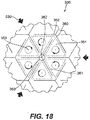
- FIGS. 18 and 19 depict auxetic element 330 under application of an inwardly-directed "pushing" force or compression 530.
- first portions 351 rotate around their centers 353, but in directions opposite to their direction of rotation under application of tension 510.
- first portions 351 that rotate around their centers 353 in a clockwise direction when under tension rotate around their centers 353 in a counter-clockwise direction when under compression.
- first portions 351 that rotate around their centers in a counter-clockwise direction when under tension rotate around their centers 353 in a clockwise direction when under compression.
- nearest-neighboring first portions 351 rotate around the second portion 352 that joins them under application of compression 530, but in directions opposite to their directions of rotation under application of tension 510.
- outwardly-opening angles 363 and inwardly-opening angles 365 decrease in magnitude
- central portion 366 and radial portions 367 decrease in area.
- one or more of angles 363 may decrease to zero magnitude
- one or more of portions 366 and 367 may decrease to zero in area.
- angles 372 between segments 371 are depicted as decreasing in magnitude, making path 370 less straight under the application of compression 530. Accordingly, for non-neighboring second portions 352 connected by path 370, a distance between those second portions 352 also decreases. Thus, the application of a compression between two second portions 352 may make a path between the second portions 352 less straight; in turn, this may induce a rotation in adjoining first portions 351, which may make an orthogonal path between other second portions 352 less straight and may thereby decrease a distance between those other second portions 352.
- auxetic element 330 is oriented along a plane extending in a first horizontal direction between forefoot region 11 and heel region 13, and extending in a second horizontal direction between medial side 14 and lateral side 15 of footwear 10.
- a tension applied to sole structure 300 in either the forefoot-heel direction (e.g., the longitudinal direction) or the medial-lateral direction will accordingly induce an expansion of auxetic element 330 along the plane in both the forefoot-heel direction and the medial-lateral direction.
- a wearer's foot may move within footwear 10, or a force having at least some forefoot-heel component or medial-lateral component may otherwise push against footwear 10, or against portions of footwear 10. This may place an outwardly-directed force (i.e., a tension) or an inwardly-directed force (i.e., a compression) upon one or more local portions of auxetic element 330.
- auxetic element 330 may then cause at least a local expansion or contraction in the structure of auxetic element 330.
- a localized tension or compression caused in the course of the wearer's use of footwear 10 may in turn induce a rotation in at least some first portions 351 near the corresponding portion of auxetic element 330, and the rotation of those first portions 351 may cause the localized expansion or localized contraction to propagate at least partially through auxetic element 330.
- tensile strands 230 may be secured in fixed position relative to specific locations along peripheral region 322 of sole structure 300, such as by being directly secured to peripheral region 322.
- peripheral region 342 of auxetic element 330 may extend to peripheral region 322 of sole structure 300 and may span an entirety of a horizontal extent of sole structure 300. Because of this, tensile strands 230 may be indirectly or directly secured to specific locations along peripheral region 342, and may thus be secured in fixed position relative to specific locations along a horizontal extent of peripheral region 322 of sole structure 300.
- tensile strands 230 may also be designed to be less stretchable than base layer 210.
- Base layer 210 may exhibit a first degree of expansion under a tension applied to upper 200, and tensile strands 230 may exhibit a second degree of expansion under the same tension, and the first degree of expansion may be greater than the second degree of expansion.
- tensile strands 230 may exhibit a degree of linear stretch that is less than the degree of linear stretch exhibited by portions of base layer 210 adjacent to tensile strands 230.
- base layer 210 may exhibit a greater degree of stretch between two locations than a tensile strand 230 having a first end 231 and a second end 232 secured to those two locations.
- the expansion of base layer 210 between two such locations may accordingly be limited more by the properties of tensile strands 230 than by the properties of base layer 210.
- tensile strands 230 may permit upper 200 to limit the transmission of tension to specific locations along auxetic element 330. This may facilitate the auxetic expansion (and contraction) of sole structure 300 with respect to specific, localized areas of auxetic element 330, which may in turn permit tuning of the localized dynamic adjustment of fit in response to an applied tension (or compression).
- the configurations of tensile strands 230 and auxetic element 330 may thus be tuned to advantageously cause footwear 10 to dynamically adjust its fit upon the wearer's foot in specific ways in response to specific forces placed upon it. For example, FIG.
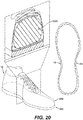
- FIG. 20 depicts an alternate embodiment of footwear 10 around a foot 1000 of a wearer.
- upper 200 does not include tensile strands
- sole structure 300 does not include an auxetic element.
- FIG. 20 depicts footwear 10 while the wearer is in a static, standing position.
- FIG. 21 the wearer is in motion, and has braced footwear 10 against the ground in order to quickly change direction, as part of a lateral "banking" or “cutting” movement.
- foot 1000 is pushing outward on lateral side 15 of upper 200.
- lateral side 15 is pushed out over sole structure 300, and a gap has been left between foot 1000 and an inner surface of upper 200 on medial side 14.
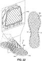
- FIG. 22 depicts the embodiment of footwear 10 of FIGS. 1-8 around foot 1000.
- the wearer begins in a static, standing position in FIG. 22 .
- FIG. 23 the wearer has just placed footwear 10 against the ground as part of a lateral "banking” or “cutting” movement, and foot 1000 has started to press against lateral side 15 of upper 200.
- FIG. 24 the wearer is in the middle of the "banking" or “cutting” movement, and has just changed the direction of movement.
- foot 1000 in FIG. 23 has not extended outward beyond the sole structure. Instead, tensile strands 230 have applied tension to specific locations along peripheral region 342 of auxetic element 330, causing auxetic element 330 to exhibit a localized auxetic expansion in response. Auxetic element 330 has extended outward and slightly upward, remaining under foot 1000. Footwear 10 is accordingly kept better conformed to the foot of the wearer.
- FIG. 25 depicts the embodiment of footwear 10 of FIGS. 1-8 as used by a wearer taking a step.
- footwear 10 and sole structure 300 have bent at an area between forefoot region 11 and midfoot region 12.
- auxetic element 330 to bend in a corresponding manner, applying a tension to auxetic element 330 in a forefoot-heel direction.
- the tension applied to auxetic element 330 in turn induces an expansion of auxetic element 330 in a forefoot-heel direction, and due to the auxetic nature of element 330, the expansion in the forefoot-heel direction in turn induces a corresponding expansion in a medial-lateral direction.
- the tension applied to the localized area of sole structure 300 may induce first portions 351 in that area to rotate (around second portions 352 that join them, and around their centers 353), may induce distances between second portions 352 in that area to increase, and may induce apertures 360 in that area to increase in area and change shape.
- Tensile strands 230 may then pull peripheral region 322 of sole structure 300 and peripheral region 342 of auxetic element 330 upward. Under tension from tensile strands 230, sole structure 300 is accordingly induced to wrap upward along the sides of footwear 10 around the area between forefoot region 11 and midfoot region 12, keeping footwear 10 better conformed to the foot of the wearer.
- tensile strands 230 have first ends 231 and second ends 232 that are fixed in position relative to peripheral region 322 of sole structure 300. In other configurations, however, first ends 231 and second ends 232 may be fixed in other positions.
- FIG. 26 depicts a configuration of footwear 10 in which first ends 231 are fixed in position relative to peripheral region 322 of sole structure 300, but second ends 232 are fixed in position relative to lace apertures 227 in lace aperture region 226 of base layer 210.
- first ends 231 and second ends 232 of tensile strands 230 may be secured to areas proximal to lace apertures 227.
- a tensile strand 230 may have a middle portions 233 fixed in position relative to a lace aperture 227, or two complementary tensile strands 230 may each have a first end 231 secured to have a fixed position relative to peripheral region 322 of sole structure 300, and may each have a second end 232 secured to have a fixed position relative to a lace aperture 227.
- Either configuration may have advantages similar to configurations in which a tensile strand 230 has a first end 231 and a second end 232 fixed in position relative to peripheral region 322 and a middle portion 233 extending around a lace aperture 227.
- At least some tensile strands 230 may not span an entire distance between peripheral region 222 and lace aperture region 226. In such configurations, at least some of tensile strands 230 may have a first end 231 secured in fixed position relative to peripheral region 322 of sole structure 300, and may have a second end 232 secured to middle region 224 of base layer 210.
- Tensile strands 230 are depicted in FIGS. 1-8 as lying adjacent to an outer surface 211 of base layer 210. In other configurations, tensile strands 230 may be otherwise situated relative to base layer 210.
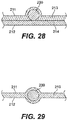
- base layer 210 comprises a first layer 213 of material at outer surface 211 of base layer 210, and a second layer of material 214 at inner surface 212 of base layer 210.
- Tensile strand 230 is situated between first layer 213 and second layer 214, and is at least partially enveloped by first layer 213.
- tensile strands 230 may be embedded within a material of base layer 210.
- Tensile strands 230 may accordingly have the configuration of the threads of the articles of footwear disclosed in U.S. Patent 7,870,681 , or the strands of the articles of footwear disclosed in U.S. Patent 8,132,340 , or the strands of the articles of footwear disclosed in U.S. Patent 8,631,589 , or the yarns of the articles of footwear disclosed in U.S. Patent 8,490,299 , such prior U.S. Patents being entirely incorporated herein by reference.
- base layer 210 may have the configuration of the knitted components of U.S. Patent 8,490,299 .
- base layer 210 can include one or more auxetic portions, allowing one or more portions of upper 200 to stretch and deform auxetically.
- base layer 210 and/or other aspects of footwear 10 can include features disclosed in U.S. Patent Application No. 14/469,973 , entitled Knitted Component Having Tensile Strand For Adjusting Auxetic Portion, which was co-filed with the present application on August 27, 2014, he disclosure of which is incorporated by reference in its entirety.
- FIGS. 1-8 depict auxetic element 330 as comprising those portions of sole structure 300 outside of sockliner 206, and as forming a ground-contacting surface of footwear 10.
- auxetic element 330 is depicted as forming an entirety of sole structure 300 outside of base layer 210.
- other configurations of sole structure 300 are possible.
- sole structure 300 may include a number of sole elements, such as a midsole element 301 and an outsole element 302.
- Midsole element 301 may be formed from a compressible polymer foam element (e.g., a polyurethane or ethylvinylacetate foam) that attenuates ground reaction forces (i.e., provides cushioning) when compressed between the foot and the ground during walking, running, or other ambulatory activities.
- Outsole element 302 may be secured to a lower surface of midsole element 301 and may be formed from a wear-resistant rubber material that is textured to impart traction.
- Auxetic element 330 may therefore include portions of midsole element 301 and outsole element 302.
- auxetic element 330 may be either a midsole element having an auxetic structure or an outsole element having an auxetic structure.
- Auxetic element 330 may accordingly be an auxetic sole element, and may include either an auxetic midsole element, and auxetic outsole element, or both.
- auxetic element 330 is depicted in FIGS. 1-8 as extending across an entirety of sole structure 300, auxetic element 330 may have an alternate span across sole structure 300. In various configurations, auxetic element 330 may extend across one or more portions of sole structure 300, but may be absent in one or more other portions of sole structure 300. Accordingly, one or more portions of sole structure 300 may be auxetic portions having an auxetic structure, and one or more portions may be non-auxetic portions without an auxetic structure.
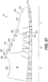
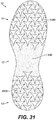
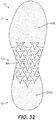
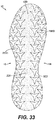
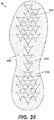
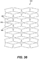
- FIGS. 31-36 depict exemplary configurations of footwear 10 in which auxetic element 330 has an alternate span.
- FIG. 31 depicts a configuration of sole structure 300 having an auxetic portion in forefoot region 11, an auxetic portion in heel region 13, and a non-auxetic portion 430 in between, in midfoot region 12.
- footwear 10 has an auxetic element 1330 in forefoot region 11, and another auxetic element 2330 in heel region 13.
- sole structure 300 is depicted in FIG. 32 as having a non-auxetic portion 1430 in forefoot region 11, a non-auxetic portion 2430 in heel region 13, and an auxetic portion in midfoot region 12, and footwear 10 accordingly has only one auxetic element 330.
- sole structure 300 is depicted as having an auxetic portion 1330 on medial side 14 and an auxetic portion 2330 on lateral side 15, separated by a non-auxetic portion running through central region 326.
- footwear 10 has two auxetic element 330.
- sole structure 300 is depicted as having an auxetic structure on both medial side 14 and lateral side 15, but the auxetic structure continues through peripheral region 322 in both forefoot region 11 and heel region 13.
- an outside portion of sole structure 300 has an auxetic structure.
- Footwear 10 thus has one auxetic element 330, spanning peripheral region 322.
- FIG. 35 depicts an inside portion of sole structure 300 as having an auxetic structure, and thus footwear 10 has one auxetic element 330 spanning central region 326.
- sole structure 300 may have various sole elements, such as a midsole element 301 or an outsole element 302, and either or both of those sole elements may be auxetic sole elements.
- sole structure 300 may have various portions, one or more of which may be auxetic, and one or more of which may be non-auxetic. Sole structure 300 may accordingly have a midsole element 301 or an outsole element 302, either one of which may have both auxetic portions and non-auxetic portions, and may therefore have a variety of auxetic elements 330.
- FIGS. 1-8 depict auxetic element 330 as having apertures that are substantially the same size and substantially the same shape when element 330 is not under tension. In other configurations, however, a size of apertures 360, or a shape of apertures 360, or both may vary across auxetic element 330.
- auxetic element 330 may have other auxetic structures.
- auxetic element 330 may have any of a variety of configurations including first portions 351, which may be regularly-shaped polygons or may be irregularly-shaped; second portions 352 joining first portions 351; and apertures 360, which may be regularly-shaped polygons or may be irregularly-shaped.
- auxetic element 330 may have a regular geometric pattern based upon polygonal units, or may have an irregular pattern, or no pattern at all. With or without regularly shaped portions 351 and apertures 360, and with or without a regular geometric pattern, auxetic element 330 may be operable to expand in two orthogonal directions under an applied tension in only one of the directions, and may be operable to contract in two orthogonal directions under an applied compression in only one of the directions.
- Auxetic element 330 may also have any of the configurations of the auxetic sole structures disclosed in U.S. Patent Application serial number 14/030,002, which was filed on September 18, 2013 and entitled "Auxetic Structures And Footwear With Soles Having Auxetic Structures," such prior U.S. Patent Application being entirely incorporated herein by reference.
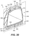
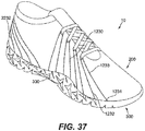
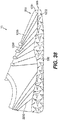
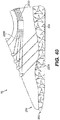
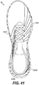
- FIGS. 37-41 depict another configuration of footwear 10.
- sole structure 300 wraps upward around lower side portions of base layer 210. Some of first portions 351, second portions 352, and apertures 360 form part of a side surface of footwear 10, and are accordingly exposed to an exterior of footwear 10 even when footwear 10 is resting on the ground.
- This alternate configuration of sole structure 300 may advantageously assist sole structure 300 in wrapping upward along the sides of footwear 10 when an auxetic expansion is induced in auxetic element 330, which may in turn increase the ability of footwear 10 to dynamically adjust its fit upon a wearer's foot and keep footwear 10 better conformed to the foot of the wearer,
- footwear 10 has four tensile strands 1230 with first ends 1231 positioned in forefoot region 11 of lateral side 15, middle portions 1233 extending around lace apertures 227, and second ends 1232 positioned in forefoot region 11 of lateral side 15.
- Footwear 10 also has four tensile strands 2230 with first ends 2231 positioned in midfoot region 12 of medial side 14, middle portions 2233 extending around heel region 13, and second ends 2232 positioned in heel region 13 of lateral side 15.
- Footwear 10 accordingly has at least two sets of tensile strands: a first set arranged to extend between lace apertures 227 and forefoot region 11 on lateral side 15, and a second set arranged to extend between midfoot region 12 on medial side 14 and heel region 13 on lateral side 15.
- This alternate configuration of tensile strands provides an upper bound to the expansion of portions of upper 200 that extend between lace apertures 227 on lateral side 15 and auxetic element 330 in forefoot region 11 of lateral side 15.
- this configuration of tensile strands also provides an upper bound to the expansion of portions of upper 200 that extend from auxetic element 330 in midfoot region 12 of medial side 14, to lace apertures 227 on medial side 14, around heel region 13, and to auxetic element 330 in heel region 13 of lateral side 15.
- Footwear 10 may thus include tensile strands 1230 having first ends 1231 and second ends 1232 positioned in the same region and side of the footwear, and footwear 10 may also include tensile strands 2230 having first ends 2231 positioned on medial side 14, and second ends 2232 positioned on lateral side 15. More generally, footwear 10 in various configurations may include tensile strands 230 having first ends 231 positioned in any region and on either side of the footwear, and second ends 232 positioned in any region and on either side of the footwear.
- the present invention may also relate to any one of the following items:
Landscapes
- Chemical & Material Sciences (AREA)
- Engineering & Computer Science (AREA)
- Materials Engineering (AREA)
- Health & Medical Sciences (AREA)
- General Health & Medical Sciences (AREA)
- Physical Education & Sports Medicine (AREA)
- Footwear And Its Accessory, Manufacturing Method And Apparatuses (AREA)
- Conductive Materials (AREA)
Applications Claiming Priority (3)
| Application Number | Priority Date | Filing Date | Title |
|---|---|---|---|
| US14/470,067 US10064448B2 (en) | 2014-08-27 | 2014-08-27 | Auxetic sole with upper cabling |
| PCT/US2015/038958 WO2016032626A1 (fr) | 2014-08-27 | 2015-07-02 | Semelle auxétique dotée d'un câblage de tige |
| EP15741426.9A EP3185715B1 (fr) | 2014-08-27 | 2015-07-02 | Semelle auxétique dotée d'un câblage de tige |
Related Parent Applications (1)
| Application Number | Title | Priority Date | Filing Date |
|---|---|---|---|
| EP15741426.9A Division EP3185715B1 (fr) | 2014-08-27 | 2015-07-02 | Semelle auxétique dotée d'un câblage de tige |
Publications (2)
| Publication Number | Publication Date |
|---|---|
| EP3430934A1 true EP3430934A1 (fr) | 2019-01-23 |
| EP3430934B1 EP3430934B1 (fr) | 2020-04-22 |
Family
ID=53718158
Family Applications (2)
| Application Number | Title | Priority Date | Filing Date |
|---|---|---|---|
| EP15741426.9A Active EP3185715B1 (fr) | 2014-08-27 | 2015-07-02 | Semelle auxétique dotée d'un câblage de tige |
| EP18193707.9A Active EP3430934B1 (fr) | 2014-08-27 | 2015-07-02 | Semelle auxétique dotée d'un câblage de tige |
Family Applications Before (1)
| Application Number | Title | Priority Date | Filing Date |
|---|---|---|---|
| EP15741426.9A Active EP3185715B1 (fr) | 2014-08-27 | 2015-07-02 | Semelle auxétique dotée d'un câblage de tige |
Country Status (7)
| Country | Link |
|---|---|
| US (2) | US10064448B2 (fr) |
| EP (2) | EP3185715B1 (fr) |
| KR (2) | KR102050010B1 (fr) |
| CN (2) | CN106714605B (fr) |
| MX (1) | MX377961B (fr) |
| TW (1) | TWI622361B (fr) |
| WO (1) | WO2016032626A1 (fr) |
Cited By (2)
| Publication number | Priority date | Publication date | Assignee | Title |
|---|---|---|---|---|
| DE102020208218A1 (de) | 2020-07-01 | 2022-01-05 | Adidas Ag | Auxetischer Artikel |
| IT202200021345A1 (it) * | 2022-10-17 | 2024-04-17 | Univ Degli Studi Di Modena E Reggio Emilia | Metamateriale auxetico |
Families Citing this family (48)
| Publication number | Priority date | Publication date | Assignee | Title |
|---|---|---|---|---|
| US9402439B2 (en) | 2013-09-18 | 2016-08-02 | Nike, Inc. | Auxetic structures and footwear with soles having auxetic structures |
| US10716360B2 (en) | 2013-09-18 | 2020-07-21 | Nike, Inc. | Sole structure with holes arranged to form an auxetic structure |
| US9456656B2 (en) | 2013-09-18 | 2016-10-04 | Nike, Inc. | Midsole component and outer sole members with auxetic structure |
| US9554622B2 (en) | 2013-09-18 | 2017-01-31 | Nike, Inc. | Multi-component sole structure having an auxetic configuration |
| US9554624B2 (en) | 2013-09-18 | 2017-01-31 | Nike, Inc. | Footwear soles with auxetic material |
| US9538811B2 (en) | 2013-09-18 | 2017-01-10 | Nike, Inc. | Sole structure with holes arranged in auxetic configuration |
| US9554620B2 (en) | 2013-09-18 | 2017-01-31 | Nike, Inc. | Auxetic soles with corresponding inner or outer liners |
| US9549590B2 (en) | 2013-09-18 | 2017-01-24 | Nike, Inc. | Auxetic structures and footwear with soles having auxetic structures |
| US9861162B2 (en) | 2014-04-08 | 2018-01-09 | Nike, Inc. | Components for articles of footwear including lightweight, selectively supported textile components |
| US9872537B2 (en) | 2014-04-08 | 2018-01-23 | Nike, Inc. | Components for articles of footwear including lightweight, selectively supported textile components |
| US10342291B2 (en) | 2014-08-25 | 2019-07-09 | Nike, Inc. | Article with sole structure having multiple components |
| US9903054B2 (en) | 2014-08-27 | 2018-02-27 | Nike, Inc. | Knitted component having tensile strand for adjusting auxetic portion |
| US10064448B2 (en) * | 2014-08-27 | 2018-09-04 | Nike, Inc. | Auxetic sole with upper cabling |
| US9854869B2 (en) * | 2014-10-01 | 2018-01-02 | Nike, Inc. | Article of footwear with one or more auxetic bladders |
| CN107205519B (zh) * | 2015-01-29 | 2021-09-28 | 耐克创新有限合伙公司 | 具有一体形成的拉胀结构的鞋类制品 |
| CN107205518B (zh) * | 2015-01-29 | 2020-09-01 | 耐克创新有限合伙公司 | 具有拉胀结构的鞋类制品 |
| EP3267822B1 (fr) * | 2015-03-10 | 2021-09-22 | Nike Innovate C.V. | Structures auxétiques et articles chaussants dotés de semelles comportant des structures auxétiques |
| WO2016144406A1 (fr) * | 2015-03-10 | 2016-09-15 | Nike Innovate C.V. | Semelles auxétiques dotées de revêtements internes ou externes correspondants |
| US9861158B2 (en) * | 2015-03-10 | 2018-01-09 | Nike, Inc. | Auxetic structures and footwear with soles having auxetic structures |
| EP3267824B1 (fr) * | 2015-03-10 | 2021-05-26 | Nike Innovate C.V. | Semelles d'articles chaussants à structures auxétiques |
| US9635903B2 (en) * | 2015-08-14 | 2017-05-02 | Nike, Inc. | Sole structure having auxetic structures and sipes |
| USD794305S1 (en) * | 2016-04-29 | 2017-08-15 | Converse Inc. | Shoe upper |
| USD819315S1 (en) * | 2016-11-12 | 2018-06-05 | Nike, Inc. | Shoe outsole |
| USD812356S1 (en) * | 2016-11-14 | 2018-03-13 | Nike, Inc. | Shoe outsole |
| CN110022714B (zh) | 2016-12-02 | 2021-04-27 | 耐克创新有限合伙公司 | 带有对齐拉伸限制件的鞋类 |
| US11399593B2 (en) * | 2017-05-25 | 2022-08-02 | Nike, Inc. | Article of footwear with auxetic sole structure having a filled auxetic aperture |
| WO2018217614A1 (fr) * | 2017-05-25 | 2018-11-29 | Nike, Inc. | Structure de semelle comportant des trous agencés pour former une structure auxétique |
| US11006696B2 (en) * | 2017-05-25 | 2021-05-18 | Nike, Inc. | Footwear with soles having auxetic structures |
| US10098409B1 (en) * | 2017-05-25 | 2018-10-16 | Nike, Inc. | Pre-tensioned article and method of making |
| CN107997291B (zh) * | 2017-12-13 | 2024-05-07 | 安踏(中国)有限公司 | 一种运动鞋 |
| US10874172B2 (en) | 2018-04-04 | 2020-12-29 | Adidas Ag | Articles of footwear with uppers comprising a wound component and methods of making the same |
| USD872441S1 (en) * | 2018-05-25 | 2020-01-14 | Nike, Inc. | Shoe |
| US11116284B2 (en) | 2018-05-31 | 2021-09-14 | Nike, Inc. | Article with auxetic spaces and method of manufacturing |
| USD880121S1 (en) * | 2018-07-26 | 2020-04-07 | Converse Inc. | Shoe |
| CN108703437B (zh) * | 2018-08-08 | 2023-12-15 | 韩栋 | 一种运动鞋中底以及外底结构 |
| CN109512083A (zh) * | 2018-12-27 | 2019-03-26 | 特步(中国)有限公司 | 一种新型吊拉鞋 |
| TWI732504B (zh) * | 2019-04-17 | 2021-07-01 | 荷蘭商耐基創新公司 | 具有分支前足帶的鞋類物品及鞋面 |
| CN114449916B (zh) * | 2019-10-04 | 2023-11-28 | 耐克创新有限合伙公司 | 鞋类鞋底夹层和用刺绣机器制造的方法 |
| US11819085B1 (en) * | 2020-01-07 | 2023-11-21 | Fast Ip, Llc | Adjustable footwear having apertures in sole structure |
| US11602196B2 (en) * | 2020-07-13 | 2023-03-14 | Adidas Ag | Articles of footwear comprising a wound component and methods of making the same |
| USD1073277S1 (en) * | 2021-03-04 | 2025-05-06 | Hui Jiang | Air cushion outsole |
| JP2023104151A (ja) * | 2022-01-17 | 2023-07-28 | 株式会社アシックス | 靴底および靴 |
| JP2023152534A (ja) | 2022-04-04 | 2023-10-17 | 株式会社アシックス | 靴底および靴 |
| US12538962B2 (en) | 2022-12-15 | 2026-02-03 | Nike, Inc. | Deconstructable footwear article |
| USD1104433S1 (en) * | 2023-10-20 | 2025-12-09 | Qinming Li | Shoe sole |
| US12553165B2 (en) | 2023-12-29 | 2026-02-17 | Adidas Ag | Rotational winding apparatus and method |
| GB2642276A (en) * | 2024-06-28 | 2026-01-07 | Pip & Henry Pvt Ltd | Auxetic outsole |
| USD1108112S1 (en) * | 2024-09-11 | 2026-01-06 | Nike, Inc. | Shoe |
Citations (8)
| Publication number | Priority date | Publication date | Assignee | Title |
|---|---|---|---|---|
| WO2007052054A1 (fr) * | 2005-11-04 | 2007-05-10 | Auxetic Technologies Limited | Procede de fabrication de mousses auxetiques |
| US20090276933A1 (en) * | 2005-02-15 | 2009-11-12 | Dodd Mark D | Protective articles having a plurality of core members |
| US7870681B2 (en) | 2006-05-25 | 2011-01-18 | Nike, Inc. | Article of footwear having an upper with thread structural elements |
| US8132340B2 (en) | 2009-04-07 | 2012-03-13 | Nike, Inc. | Footwear incorporating crossed tensile strand elements |
| US8490299B2 (en) | 2008-12-18 | 2013-07-23 | Nike, Inc. | Article of footwear having an upper incorporating a knitted component |
| US20130219636A1 (en) * | 2012-02-24 | 2013-08-29 | Nike, Inc. | Methods Of Manufacturing Articles Of Footwear With Tensile Strand Elements |
| US8631589B2 (en) | 2010-07-30 | 2014-01-21 | Nike, Inc. | Article of footwear incorporating floating tensile strands |
| US20140101816A1 (en) * | 2012-08-31 | 2014-04-17 | Under Armour, Inc. | Articles of Apparel Including Auxetic Materials |
Family Cites Families (183)
| Publication number | Priority date | Publication date | Assignee | Title |
|---|---|---|---|---|
| US503062A (en) | 1893-08-08 | Of boston | ||
| US1733733A (en) | 1928-11-20 | 1929-10-29 | Edgar H Hess | Shoe and cushioning member or middle sole therefor |
| US2251468A (en) | 1939-04-05 | 1941-08-05 | Salta Corp | Rubber shoe sole |
| US2432533A (en) | 1944-04-25 | 1947-12-16 | Margolin Meyer | Ventilated midsole |
| US2580840A (en) | 1948-10-19 | 1952-01-01 | Rogndal Rikard | Lightweight, flexible, resilient, and nonskid sole for footwear |
| US2963722A (en) | 1958-08-26 | 1960-12-13 | Us Shoc Corp | Method of shoe construction |
| US3138880A (en) * | 1963-01-29 | 1964-06-30 | Bennett Inc | Athletic shoe |
| US3745600A (en) | 1969-03-07 | 1973-07-17 | J Rubico | Method of making shoes over sheathed last utilizing a lasting element |
| GB1262204A (en) | 1969-09-05 | 1972-02-02 | British United Shoe Machinery | Improvements in or relating to a method of making shoes |
| US3757436A (en) | 1972-12-04 | 1973-09-11 | Compo Ind Inc | Apparatus provided with lasting tabs and method of lasting |
| FR2331297A1 (fr) | 1975-11-13 | 1977-06-10 | Ours Rosette | Procede de fabrication de chaussures a tige haute et chaussures ainsi fabriquees |
| US4340626A (en) | 1978-05-05 | 1982-07-20 | Rudy Marion F | Diffusion pumping apparatus self-inflating device |
| US4272850A (en) | 1979-05-25 | 1981-06-16 | W. H. Brine Company | Body protective pads |
| AU1358183A (en) | 1982-04-15 | 1983-10-20 | Slaughter, J.H. | Footwear |
| US4484398A (en) | 1983-07-21 | 1984-11-27 | Goodwin Boyd G | Spiked shoe protector |
| US4668557A (en) * | 1986-07-18 | 1987-05-26 | The University Of Iowa Research Foundation | Polyhedron cell structure and method of making same |
| US4756098A (en) | 1987-01-21 | 1988-07-12 | Gencorp Inc. | Athletic shoe |
| US4858340A (en) | 1988-02-16 | 1989-08-22 | Prince Manufacturing, Inc. | Shoe with form fitting sole |
| CA1338369C (fr) | 1988-02-24 | 1996-06-11 | Jean-Pierre Vermeulen | Dispositif amortisseur pour chaussures |
| US4967492A (en) | 1988-07-29 | 1990-11-06 | Rosen Henri E | Adjustable girth shoes |
| US4899412A (en) | 1988-09-07 | 1990-02-13 | R. G. Barry Corporation | Slipper and method of making same |
| US5060402A (en) | 1989-02-17 | 1991-10-29 | Rosen Henri E | Adjustable girth shoe construction |
| ES2155820T3 (es) | 1990-01-10 | 2001-06-01 | Anatomic Res Inc | Suela para calzado. |
| USD339459S (en) | 1991-11-05 | 1993-09-21 | Asics Corporation | Shoe sole |
| USD344170S (en) | 1991-11-18 | 1994-02-15 | Acoff Roy B | Tennis shoes |
| KR100272751B1 (ko) * | 1994-02-28 | 2002-11-22 | 아담 에이치 오렉 | 헤이스 튜브를 가진 신발 |
| US5718064A (en) | 1994-04-04 | 1998-02-17 | Nine West Group Inc. | Multi-layer sole construction for walking shoes |
| US5469639A (en) | 1994-12-02 | 1995-11-28 | Sessa; Raymond V. | Shoe sole having insert with graduated cushioning properties |
| US5729912A (en) | 1995-06-07 | 1998-03-24 | Nike, Inc. | Article of footwear having adjustable width, footform and cushioning |
| USD420786S (en) | 1995-09-21 | 2000-02-22 | Pillow Tech International Ltd. | Spikeless golf shoe sole |
| MA24022A1 (fr) | 1995-12-04 | 1997-07-01 | Global Sports Tech Inc | Chaussure de sport avec un groupe de semelle comprenant au minimum une couche de materiau composite qui entoure partiellement ce meme groupe de semelle |
| JPH08275805A (ja) * | 1995-12-11 | 1996-10-22 | Koichi Nakazato | 靴 |
| DE19601219C1 (de) | 1996-01-15 | 1997-01-02 | Rudolf Hieblinger | Sportschuh, insbesondere Fußballschuh |
| US5926974A (en) | 1997-01-17 | 1999-07-27 | Nike, Inc. | Footwear with mountain goat traction elements |
| US6298582B1 (en) * | 1998-01-30 | 2001-10-09 | Nike, Inc. | Article of footwear with heel clip |
| GB9805619D0 (en) | 1998-03-18 | 1998-05-13 | Noise Cancellation Tech | Cushioned earphones |
| US6519876B1 (en) | 1998-05-06 | 2003-02-18 | Kenton Geer Design Associates, Inc. | Footwear structure and method of forming the same |
| GB2341308B (en) | 1998-09-14 | 2001-03-28 | Mitre Sports Internat Ltd | Sports footwear and studs therefor |
| US6178662B1 (en) | 1999-02-02 | 2001-01-30 | David K. Legatzke | Dispersed-air footpad |
| WO2001001807A1 (fr) | 1999-07-01 | 2001-01-11 | K-Swiss, Inc. | Element d'insertion de semelle intercalaire amortissante pour chaussure d'athletisme |
| US6564476B1 (en) | 1999-07-02 | 2003-05-20 | Bbc International, Ltd. | Flex sole |
| US20020166262A1 (en) | 1999-07-02 | 2002-11-14 | Bbc International Ltd. | Flex sole with mesh insert enhancement |
| US6571490B2 (en) | 2000-03-16 | 2003-06-03 | Nike, Inc. | Bladder with multi-stage regionalized cushioning |
| DE10036100C1 (de) | 2000-07-25 | 2002-02-14 | Adidas Int Bv | Schuh |
| ES2346743T3 (es) | 2001-09-13 | 2010-10-20 | Daniel James Plant | Material flexible absorbente de energia y procedimientos de fabricacion del mismo. |
| FR2836340B1 (fr) | 2002-02-28 | 2004-09-03 | Salomon Sa | Article chaussant a serrage elastique |
| CN2549784Y (zh) * | 2002-06-13 | 2003-05-14 | 钰齐有限公司 | 鞋带快速穿扣以及具有该种鞋带快速穿扣的鞋子 |
| US6763611B1 (en) * | 2002-07-15 | 2004-07-20 | Nike, Inc. | Footwear sole incorporating a lattice structure |
| USD488916S1 (en) * | 2003-01-31 | 2004-04-27 | Columbia Insurance Company | Outsole |
| US7254906B2 (en) | 2003-02-24 | 2007-08-14 | Kwame Morris | Foot cushioning construct and system for use in an article of footwear |
| US20040181972A1 (en) | 2003-03-19 | 2004-09-23 | Julius Csorba | Mechanism of tying of shoes circumferentially embracing the foot within the shoe |
| USD487614S1 (en) | 2003-05-15 | 2004-03-23 | Wolverine World Wide, Inc. | Footwear sole |
| JP2005143637A (ja) | 2003-11-12 | 2005-06-09 | Shoken Ki | 靴の製造方法 |
| US7562469B2 (en) * | 2003-12-23 | 2009-07-21 | Nike, Inc. | Footwear with fluid-filled bladder and a reinforcing structure |
| ITPD20030312A1 (it) * | 2003-12-30 | 2005-06-30 | Geox Spa | Suola traspirante ed impermeabile per calzature |
| US7252870B2 (en) * | 2003-12-31 | 2007-08-07 | Kimberly-Clark Worldwide, Inc. | Nonwovens having reduced Poisson ratio |
| GB0402103D0 (en) | 2004-02-02 | 2004-03-03 | Hengelmolen Rudy | Tubular graft |
| US7598651B2 (en) | 2004-03-12 | 2009-10-06 | Sri International | Mechanical meta-materials |
| US7160621B2 (en) | 2004-06-28 | 2007-01-09 | General Electric Company | Energy absorbing articles |
| GB0418759D0 (en) | 2004-08-23 | 2004-09-22 | Auxetix Ltd | Uses of auxetic fibres |
| US7475497B2 (en) | 2005-01-18 | 2009-01-13 | Nike, Inc. | Article of footwear with a perforated midsole |
| US8961733B2 (en) | 2005-02-15 | 2015-02-24 | Pinwrest Development Group, Llc | Method of improving the impact-protective properties of a conformable substrate |
| US8220072B2 (en) | 2005-02-15 | 2012-07-17 | The Dodd Group, LLC | Protective shin guard |
| ITTV20050044A1 (it) | 2005-03-25 | 2006-09-26 | Bruno Zanatta | Struttura di calzatura a calzata regolabile |
| US7310894B1 (en) | 2005-05-12 | 2007-12-25 | Schwarzman John L | Footwear for use in shower |
| US7401418B2 (en) | 2005-08-17 | 2008-07-22 | Nike, Inc. | Article of footwear having midsole with support pillars and method of manufacturing same |
| CN2870531Y (zh) | 2005-10-13 | 2007-02-21 | 李锡宏 | 一种透气鞋底 |
| US8084117B2 (en) | 2005-11-29 | 2011-12-27 | Haresh Lalvani | Multi-directional and variably expanded sheet material surfaces |
| US20070240333A1 (en) | 2006-04-12 | 2007-10-18 | Deckers Outdoor Corporation | Chassis for footwear and method of making footwear |
| US8312646B2 (en) * | 2006-05-25 | 2012-11-20 | Nike, Inc. | Article of footwear incorporating a tensile element |
| US8904671B2 (en) * | 2006-05-25 | 2014-12-09 | Nike, Inc. | Footwear incorporating a tensile element with a deposition layer |
| US7574818B2 (en) | 2006-05-25 | 2009-08-18 | Nike, Inc. | Article of footwear having an upper with thread structural elements |
| US8312645B2 (en) * | 2006-05-25 | 2012-11-20 | Nike, Inc. | Material elements incorporating tensile strands |
| US7546698B2 (en) | 2006-05-25 | 2009-06-16 | Nike, Inc. | Article of footwear having an upper with thread structural elements |
| US8418380B2 (en) * | 2006-05-25 | 2013-04-16 | Nike, Inc. | Article of footwear having an upper incorporating a tensile strand with a cover layer |
| BRPI0621717B1 (pt) | 2006-06-20 | 2018-06-26 | Geox S.P.A. | " sola compreendendo um elemento permeável a vapor e calçado compreendendo a mesma" |
| US20080011021A1 (en) | 2006-06-27 | 2008-01-17 | Hbi Branded Apparel Enterprises, Llc. | Fabrics having knit structures exhibiting auxetic properties and garments formed thereby |
| US7685740B2 (en) * | 2006-07-13 | 2010-03-30 | Nike, Inc. | Dance shoe |
| US7455567B2 (en) | 2006-08-02 | 2008-11-25 | Hanesbrands Inc. | Garments having auxetic foam layers |
| US8225530B2 (en) | 2006-11-10 | 2012-07-24 | Nike, Inc. | Article of footwear having a flat knit upper construction or other upper construction |
| USD614382S1 (en) | 2006-12-06 | 2010-04-27 | Salomon S.A.S. | Footwear |
| USD571543S1 (en) | 2007-02-26 | 2008-06-24 | J. S. Company Orlando Inc. | Pair of outsoles for a woman's shoes |
| EP2674051B1 (fr) | 2007-02-28 | 2018-12-26 | NIKE Innovate C.V. | Article de chaussure ayant un motif de semelle à crampons en polygone |
| US8652602B1 (en) * | 2007-02-28 | 2014-02-18 | William Jacob Spenner Dolla | Rotational expansion auxetic structures |
| US7788827B2 (en) | 2007-03-06 | 2010-09-07 | Nike, Inc. | Article of footwear with mesh on outsole and insert |
| US7797856B2 (en) | 2007-04-10 | 2010-09-21 | Reebok International Ltd. | Lightweight sole for article of footwear |
| WO2008130839A1 (fr) | 2007-04-18 | 2008-10-30 | Nike, Inc. | Article de construction de chaussures avec des parties de liaison |
| GB2455167A (en) | 2007-09-04 | 2009-06-03 | Univ Malta | Bimetallic or bimaterial members and systems which exhibit negative Poisson's ratio |
| CN101815448B (zh) | 2007-09-06 | 2011-12-14 | 帕迪斯科发展有限公司 | 弹簧鞋 |
| US7934325B2 (en) | 2007-09-07 | 2011-05-03 | Nike, Inc. | Gymnastics footwear |
| US8302233B2 (en) | 2007-09-11 | 2012-11-06 | Nike, Inc. | Method of making an article of footwear and apparatus |
| US7926204B2 (en) * | 2007-10-11 | 2011-04-19 | Nike, Inc. | Article of footwear with tubular sole assembly and method of manufacture |
| US9795181B2 (en) | 2007-10-23 | 2017-10-24 | Nike, Inc. | Articles and methods of manufacture of articles |
| US8241450B2 (en) | 2007-12-17 | 2012-08-14 | Nike, Inc. | Method for inflating a fluid-filled chamber |
| US8341857B2 (en) | 2008-01-16 | 2013-01-01 | Nike, Inc. | Fluid-filled chamber with a reinforced surface |
| WO2009091988A1 (fr) | 2008-01-18 | 2009-07-23 | Nike, Inc. | Article de fabrication à taille ajustable, en particulier une chaussure, et son procédé de construction modulaire |
| ITCT20080001U1 (it) | 2008-03-07 | 2009-09-08 | Meli Giuseppe | Dispositivo perfezionato per la produzione di strutture composite con sezione piana a geometria assimetrica chirale o auxetic ma utilizzabile per la produzione di grigliati di qualunque forma.realizzabile anche attraverso la compenetrazione di elemen |
| CA2728485C (fr) | 2008-06-17 | 2017-10-31 | Brown Shoe Company, Inc. | Chaussure a semelle d'usure de traction |
| US8122616B2 (en) | 2008-07-25 | 2012-02-28 | Nike, Inc. | Composite element with a polymer connecting layer |
| US20100043255A1 (en) | 2008-08-21 | 2010-02-25 | Trevino Steven M | External sole liner and method of manufacturing and using the same |
| GB2463446A (en) | 2008-09-15 | 2010-03-17 | Auxetic Technologies Ltd | Honeycomb construction system |
| US20110247237A1 (en) | 2008-10-06 | 2011-10-13 | Michelin Recherche Et Technique S.A. | Shoe with Anti-Skid Sole |
| US8516723B2 (en) | 2008-10-08 | 2013-08-27 | Nike, Inc. | Midfoot insert construction |
| CN102215710B (zh) | 2008-10-10 | 2014-01-22 | 耐克国际有限公司 | 具有中底结构的鞋类物品 |
| US20100095551A1 (en) | 2008-10-16 | 2010-04-22 | Honey Gupta | Footwear, footwear inserts and socks for reducing contact forces |
| US8544515B2 (en) | 2008-11-10 | 2013-10-01 | Mkp Structural Design Associates, Inc. | Ultralightweight runflat tires based upon negative poisson ratio (NPR) auxetic structures |
| US20100126041A1 (en) | 2008-11-17 | 2010-05-27 | Altama Footwear | Foot-Bed |
| EP2361023B1 (fr) * | 2008-12-19 | 2013-02-13 | Daniel James Plant | Système absorbant l'énergie |
| US8112907B2 (en) | 2009-01-03 | 2012-02-14 | Eric Byeung Kim | Disposable cushion shoe insert |
| US8196316B2 (en) | 2009-01-26 | 2012-06-12 | Nike, Inc. | Article of footwear with two part midsole assembly |
| US8171655B2 (en) | 2009-03-18 | 2012-05-08 | Wolverine World Wide, Inc. | Sole construction and related method of manufacture |
| US8388791B2 (en) | 2009-04-07 | 2013-03-05 | Nike, Inc. | Method for molding tensile strand elements |
| WO2010125397A1 (fr) * | 2009-05-01 | 2010-11-04 | Global Composites Group | Tissu tricoté auxétique |
| GB0910621D0 (en) | 2009-06-19 | 2009-08-05 | Univ Exeter | Auxetic material |
| US9500245B2 (en) | 2009-06-22 | 2016-11-22 | Powerdisk Development Ltd. | Springs for shoes |
| US9015962B2 (en) * | 2010-03-26 | 2015-04-28 | Reebok International Limited | Article of footwear with support element |
| DE102009028627B4 (de) * | 2009-08-18 | 2019-12-19 | Adidas Ag | Sportschuh |
| US8266827B2 (en) * | 2009-08-24 | 2012-09-18 | Nike, Inc. | Article of footwear incorporating tensile strands and securing strands |
| IT1395799B1 (it) | 2009-10-06 | 2012-10-26 | Meise Holding Gmbh | Suola per calzature che favorisce la traspirazione del piede. |
| US20110099845A1 (en) | 2009-11-03 | 2011-05-05 | Miller Michael J | Customized footwear and methods for manufacturing |
| GB0919416D0 (en) * | 2009-11-06 | 2009-12-23 | Rolls Royce Plc | A method of manufacturing a foam |
| FR2952790B1 (fr) | 2009-11-23 | 2012-01-06 | Salomon Sas | Chaussure a semelage ameliore |
| US20110192056A1 (en) | 2010-02-05 | 2011-08-11 | Deckers Outdoor Corporation | Footwear including a self-adjusting midsole |
| US8544197B2 (en) * | 2010-02-11 | 2013-10-01 | Nike, Inc. | Article of footwear incorporating an illuminable panel |
| GB201003012D0 (en) | 2010-02-23 | 2010-04-07 | Rolls Royce Plc | Vibration damping structures |
| US8479414B2 (en) | 2010-03-01 | 2013-07-09 | Nike, Inc. | Footwear insole |
| US8844171B2 (en) | 2010-04-07 | 2014-09-30 | Nike, Inc. | Article of footwear with a ball contacting surface |
| US8595878B2 (en) | 2010-08-02 | 2013-12-03 | Nike, Inc. | Method of lasting an article of footwear |
| FR2966394B1 (fr) | 2010-10-22 | 2013-06-28 | Inergy Automotive Systems Res | Reservoir pour vehicule et/ou tubulure de remplissage pour un tel reservoir |
| US8322050B2 (en) * | 2010-11-05 | 2012-12-04 | Shoes For Crews, Llc | Outsole tread pattern |
| US20120124865A1 (en) | 2010-11-12 | 2012-05-24 | Steve Opie | Court shoe cover |
| IT1402785B1 (it) | 2010-11-19 | 2013-09-18 | Geox Spa | Calzatura traspirante con suola impermeabile e traspirante |
| US8707587B2 (en) * | 2010-12-29 | 2014-04-29 | Reebok International Limited | Sole and article of footwear |
| US9055784B2 (en) | 2011-01-06 | 2015-06-16 | Nike, Inc. | Article of footwear having a sole structure incorporating a plate and chamber |
| US8732982B2 (en) | 2011-01-18 | 2014-05-27 | Saucony IP Holdings, LLC | Footwear |
| TW201231283A (en) | 2011-01-25 | 2012-08-01 | Ying-Chun Huang | A method of improving friction resistance |
| US9107474B2 (en) | 2011-02-04 | 2015-08-18 | Nike, Inc. | Article of footwear with decoupled upper |
| US8522577B2 (en) | 2011-03-15 | 2013-09-03 | Nike, Inc. | Combination feeder for a knitting machine |
| US9021720B2 (en) | 2011-03-16 | 2015-05-05 | Nike, Inc. | Fluid-filled chamber with a tensile member |
| US20120272550A1 (en) | 2011-03-21 | 2012-11-01 | Gloria Parce | PeepZ Cleat Covers |
| US8950089B2 (en) | 2011-04-20 | 2015-02-10 | Keen, Inc. | Heat retention and insulation system for wearable articles |
| GB201109949D0 (en) | 2011-06-14 | 2011-07-27 | Dow Corning | Pressure material |
| KR101165793B1 (ko) | 2011-08-26 | 2012-07-16 | (주)지원에프알에스 | 충격 흡수성과 분산성 및 유연성이 강화된 신발창 |
| USD653844S1 (en) | 2011-09-22 | 2012-02-14 | Nike, Inc. | Shoe outsole |
| US8595956B2 (en) | 2011-09-29 | 2013-12-03 | C. & J. Clark International Limited | Footwear with elastic footbed cover and soft foam footbed |
| US20130104428A1 (en) | 2011-10-26 | 2013-05-02 | Chad O'Brien | Athletic Shoe Sole Cover |
| US9295304B2 (en) | 2011-12-21 | 2016-03-29 | Nike, Inc. | Articles of footwear |
| US9491984B2 (en) | 2011-12-23 | 2016-11-15 | Nike, Inc. | Article of footwear having an elevated plate sole structure |
| USD717034S1 (en) | 2011-12-29 | 2014-11-11 | Vibram S.P.A. | Sole for footwear |
| US8887410B2 (en) * | 2012-02-24 | 2014-11-18 | Nike, Inc. | Articles of footwear with tensile strand elements |
| CN103287025B (zh) | 2012-02-28 | 2015-12-02 | 香港纺织及成衣研发中心有限公司 | 一种三维负泊松比间隔针织物及其制作方法 |
| WO2013138439A1 (fr) | 2012-03-13 | 2013-09-19 | New Balance Athletic Shoe, Inc. | Parties en mousse ayant un composant de tissu et systèmes et procédés de fabrication associés |
| AU2013309017B2 (en) * | 2012-08-27 | 2016-12-08 | Nike Innovate C.V. | Dynamic materials integrated into articles for adjustable physical dimensional characteristics |
| US9629397B2 (en) * | 2012-08-31 | 2017-04-25 | Under Armour, Inc. | Articles of apparel including auxetic materials |
| JP6302478B2 (ja) * | 2012-11-27 | 2018-03-28 | ナイキ イノヴェイト シーヴィーNike Innovate C.V. | 足首インレイストランドを用いた履物のニット構成要素 |
| US9066558B2 (en) | 2012-12-17 | 2015-06-30 | Nike, Inc. | Electronically controlled bladder assembly |
| US9872535B2 (en) | 2012-12-20 | 2018-01-23 | Nike, Inc. | Article of footwear with a harness and fluid-filled chamber arrangement |
| US20140237850A1 (en) | 2013-02-22 | 2014-08-28 | Nike, Inc. | Footwear With Reactive Layers |
| US9226540B2 (en) * | 2013-02-28 | 2016-01-05 | Nike, Inc. | Method of knitting a knitted component with a vertically inlaid tensile element |
| US9709274B2 (en) * | 2013-03-15 | 2017-07-18 | Rolls-Royce Plc | Auxetic structure with stress-relief features |
| US9060567B2 (en) * | 2013-03-22 | 2015-06-23 | Nike, Inc. | Article of footwear with tensile structure |
| ES2731561T3 (es) | 2013-05-24 | 2019-11-15 | Ecco Sko As | Artículo de calzado y método para formar el artículo |
| US9538811B2 (en) * | 2013-09-18 | 2017-01-10 | Nike, Inc. | Sole structure with holes arranged in auxetic configuration |
| US9554622B2 (en) * | 2013-09-18 | 2017-01-31 | Nike, Inc. | Multi-component sole structure having an auxetic configuration |
| US9554620B2 (en) * | 2013-09-18 | 2017-01-31 | Nike, Inc. | Auxetic soles with corresponding inner or outer liners |
| US9402439B2 (en) | 2013-09-18 | 2016-08-02 | Nike, Inc. | Auxetic structures and footwear with soles having auxetic structures |
| US9456656B2 (en) * | 2013-09-18 | 2016-10-04 | Nike, Inc. | Midsole component and outer sole members with auxetic structure |
| US9549590B2 (en) * | 2013-09-18 | 2017-01-24 | Nike, Inc. | Auxetic structures and footwear with soles having auxetic structures |
| US9554624B2 (en) * | 2013-09-18 | 2017-01-31 | Nike, Inc. | Footwear soles with auxetic material |
| USD707934S1 (en) | 2013-11-30 | 2014-07-01 | Nike, Inc. | Shoe outsole |
| USD716027S1 (en) * | 2014-02-28 | 2014-10-28 | Nike, Inc. | Shoe outsole |
| US9474326B2 (en) | 2014-07-11 | 2016-10-25 | Nike, Inc. | Footwear having auxetic structures with controlled properties |
| US10064448B2 (en) | 2014-08-27 | 2018-09-04 | Nike, Inc. | Auxetic sole with upper cabling |
| US9192204B1 (en) * | 2014-09-30 | 2015-11-24 | Nike, Inc. | Article of footwear upper incorporating a textile component with tensile elements |
| US9854869B2 (en) * | 2014-10-01 | 2018-01-02 | Nike, Inc. | Article of footwear with one or more auxetic bladders |
| US9775408B2 (en) * | 2014-12-09 | 2017-10-03 | Nike, Inc. | Footwear with auxetic ground engaging members |
| US9901135B2 (en) * | 2014-12-09 | 2018-02-27 | Nike, Inc. | Footwear with flexible auxetic ground engaging members |
| US9681703B2 (en) * | 2014-12-09 | 2017-06-20 | Nike, Inc. | Footwear with flexible auxetic sole structure |
| CN107205519B (zh) * | 2015-01-29 | 2021-09-28 | 耐克创新有限合伙公司 | 具有一体形成的拉胀结构的鞋类制品 |
| US9861158B2 (en) * | 2015-03-10 | 2018-01-09 | Nike, Inc. | Auxetic structures and footwear with soles having auxetic structures |
| US9848674B2 (en) * | 2015-04-14 | 2017-12-26 | Nike, Inc. | Article of footwear with weight-activated cinching apparatus |
| US9668542B2 (en) * | 2015-08-14 | 2017-06-06 | Nike, Inc. | Sole structure including sipes |
| US9635903B2 (en) * | 2015-08-14 | 2017-05-02 | Nike, Inc. | Sole structure having auxetic structures and sipes |
-
2014
- 2014-08-27 US US14/470,067 patent/US10064448B2/en active Active
-
2015
- 2015-07-02 EP EP15741426.9A patent/EP3185715B1/fr active Active
- 2015-07-02 KR KR1020197003170A patent/KR102050010B1/ko active Active
- 2015-07-02 WO PCT/US2015/038958 patent/WO2016032626A1/fr not_active Ceased
- 2015-07-02 KR KR1020177008127A patent/KR101947930B1/ko active Active
- 2015-07-02 MX MX2017002397A patent/MX377961B/es unknown
- 2015-07-02 CN CN201580046068.6A patent/CN106714605B/zh active Active
- 2015-07-02 EP EP18193707.9A patent/EP3430934B1/fr active Active
- 2015-07-02 CN CN201910772042.XA patent/CN110477510B/zh active Active
- 2015-07-24 TW TW104124156A patent/TWI622361B/zh active
-
2018
- 2018-08-27 US US16/113,288 patent/US11013293B2/en active Active
Patent Citations (8)
| Publication number | Priority date | Publication date | Assignee | Title |
|---|---|---|---|---|
| US20090276933A1 (en) * | 2005-02-15 | 2009-11-12 | Dodd Mark D | Protective articles having a plurality of core members |
| WO2007052054A1 (fr) * | 2005-11-04 | 2007-05-10 | Auxetic Technologies Limited | Procede de fabrication de mousses auxetiques |
| US7870681B2 (en) | 2006-05-25 | 2011-01-18 | Nike, Inc. | Article of footwear having an upper with thread structural elements |
| US8490299B2 (en) | 2008-12-18 | 2013-07-23 | Nike, Inc. | Article of footwear having an upper incorporating a knitted component |
| US8132340B2 (en) | 2009-04-07 | 2012-03-13 | Nike, Inc. | Footwear incorporating crossed tensile strand elements |
| US8631589B2 (en) | 2010-07-30 | 2014-01-21 | Nike, Inc. | Article of footwear incorporating floating tensile strands |
| US20130219636A1 (en) * | 2012-02-24 | 2013-08-29 | Nike, Inc. | Methods Of Manufacturing Articles Of Footwear With Tensile Strand Elements |
| US20140101816A1 (en) * | 2012-08-31 | 2014-04-17 | Under Armour, Inc. | Articles of Apparel Including Auxetic Materials |
Cited By (6)
| Publication number | Priority date | Publication date | Assignee | Title |
|---|---|---|---|---|
| DE102020208218A1 (de) | 2020-07-01 | 2022-01-05 | Adidas Ag | Auxetischer Artikel |
| EP3933083A3 (fr) * | 2020-07-01 | 2022-01-12 | adidas AG | Article auxétique |
| DE102020208218B4 (de) | 2020-07-01 | 2022-02-10 | Adidas Ag | Auxetischer Artikel |
| EP4428282A1 (fr) * | 2020-07-01 | 2024-09-11 | adidas AG | Article auxétique |
| US12392060B2 (en) | 2020-07-01 | 2025-08-19 | Adidas Ag | Auxetic article |
| IT202200021345A1 (it) * | 2022-10-17 | 2024-04-17 | Univ Degli Studi Di Modena E Reggio Emilia | Metamateriale auxetico |
Also Published As
| Publication number | Publication date |
|---|---|
| US10064448B2 (en) | 2018-09-04 |
| US20160058121A1 (en) | 2016-03-03 |
| EP3185715B1 (fr) | 2018-10-03 |
| CN106714605A (zh) | 2017-05-24 |
| MX377961B (es) | 2025-03-10 |
| CN110477510A (zh) | 2019-11-22 |
| CN110477510B (zh) | 2021-09-28 |
| MX2017002397A (es) | 2017-09-13 |
| EP3430934B1 (fr) | 2020-04-22 |
| KR101947930B1 (ko) | 2019-02-13 |
| KR20190014598A (ko) | 2019-02-12 |
| EP3185715A1 (fr) | 2017-07-05 |
| US11013293B2 (en) | 2021-05-25 |
| KR102050010B1 (ko) | 2019-11-28 |
| TW201611739A (en) | 2016-04-01 |
| WO2016032626A1 (fr) | 2016-03-03 |
| KR20170048436A (ko) | 2017-05-08 |
| CN106714605B (zh) | 2019-09-10 |
| US20180360163A1 (en) | 2018-12-20 |
| TWI622361B (zh) | 2018-05-01 |
Similar Documents
| Publication | Publication Date | Title |
|---|---|---|
| US11013293B2 (en) | Auxetic sole with upper cabling | |
| EP3677139B1 (fr) | Empeigne pour article de chaussure comportant une configuration auxétique | |
| CN104350192B (zh) | 间隔织物材料及用于制造间隔织物材料的方法 | |
| EP1903898B1 (fr) | Chaussure formee d'une tige avec une couche matricielle | |
| US8745901B2 (en) | Article of footwear with tongue and heel openings | |
| CN105188449B (zh) | 具有多个未焊接的折曲区的鞋的鞋面 | |
| CN102595951A (zh) | 具有包含抗拉线与覆盖层的鞋面的鞋类物品 | |
| CN106174842A (zh) | 具有带有鞋前部承拉线元件的鞋面的鞋 | |
| EP2906067B1 (fr) | Traitement anti-allongement de cuir pour articles chaussants |
Legal Events
| Date | Code | Title | Description |
|---|---|---|---|
| PUAI | Public reference made under article 153(3) epc to a published international application that has entered the european phase |
Free format text: ORIGINAL CODE: 0009012 |
|
| STAA | Information on the status of an ep patent application or granted ep patent |
Free format text: STATUS: THE APPLICATION HAS BEEN PUBLISHED |
|
| AC | Divisional application: reference to earlier application |
Ref document number: 3185715 Country of ref document: EP Kind code of ref document: P |
|
| AK | Designated contracting states |
Kind code of ref document: A1 Designated state(s): AL AT BE BG CH CY CZ DE DK EE ES FI FR GB GR HR HU IE IS IT LI LT LU LV MC MK MT NL NO PL PT RO RS SE SI SK SM TR |
|
| STAA | Information on the status of an ep patent application or granted ep patent |
Free format text: STATUS: REQUEST FOR EXAMINATION WAS MADE |
|
| 17P | Request for examination filed |
Effective date: 20190711 |
|
| RBV | Designated contracting states (corrected) |
Designated state(s): AL AT BE BG CH CY CZ DE DK EE ES FI FR GB GR HR HU IE IS IT LI LT LU LV MC MK MT NL NO PL PT RO RS SE SI SK SM TR |
|
| GRAP | Despatch of communication of intention to grant a patent |
Free format text: ORIGINAL CODE: EPIDOSNIGR1 |
|
| STAA | Information on the status of an ep patent application or granted ep patent |
Free format text: STATUS: GRANT OF PATENT IS INTENDED |
|
| INTG | Intention to grant announced |
Effective date: 20191111 |
|
| GRAS | Grant fee paid |
Free format text: ORIGINAL CODE: EPIDOSNIGR3 |
|
| GRAA | (expected) grant |
Free format text: ORIGINAL CODE: 0009210 |
|
| STAA | Information on the status of an ep patent application or granted ep patent |
Free format text: STATUS: THE PATENT HAS BEEN GRANTED |
|
| AC | Divisional application: reference to earlier application |
Ref document number: 3185715 Country of ref document: EP Kind code of ref document: P |
|
| AK | Designated contracting states |
Kind code of ref document: B1 Designated state(s): AL AT BE BG CH CY CZ DE DK EE ES FI FR GB GR HR HU IE IS IT LI LT LU LV MC MK MT NL NO PL PT RO RS SE SI SK SM TR |
|
| REG | Reference to a national code |
Ref country code: CH Ref legal event code: EP |
|
| REG | Reference to a national code |
Ref country code: DE Ref legal event code: R096 Ref document number: 602015051460 Country of ref document: DE |
|
| REG | Reference to a national code |
Ref country code: IE Ref legal event code: FG4D |
|
| REG | Reference to a national code |
Ref country code: AT Ref legal event code: REF Ref document number: 1258910 Country of ref document: AT Kind code of ref document: T Effective date: 20200515 |
|
| REG | Reference to a national code |
Ref country code: LT Ref legal event code: MG4D |
|
| REG | Reference to a national code |
Ref country code: NL Ref legal event code: MP Effective date: 20200422 |
|
| PG25 | Lapsed in a contracting state [announced via postgrant information from national office to epo] |
Ref country code: SE Free format text: LAPSE BECAUSE OF FAILURE TO SUBMIT A TRANSLATION OF THE DESCRIPTION OR TO PAY THE FEE WITHIN THE PRESCRIBED TIME-LIMIT Effective date: 20200422 Ref country code: NO Free format text: LAPSE BECAUSE OF FAILURE TO SUBMIT A TRANSLATION OF THE DESCRIPTION OR TO PAY THE FEE WITHIN THE PRESCRIBED TIME-LIMIT Effective date: 20200722 Ref country code: FI Free format text: LAPSE BECAUSE OF FAILURE TO SUBMIT A TRANSLATION OF THE DESCRIPTION OR TO PAY THE FEE WITHIN THE PRESCRIBED TIME-LIMIT Effective date: 20200422 Ref country code: IS Free format text: LAPSE BECAUSE OF FAILURE TO SUBMIT A TRANSLATION OF THE DESCRIPTION OR TO PAY THE FEE WITHIN THE PRESCRIBED TIME-LIMIT Effective date: 20200822 Ref country code: GR Free format text: LAPSE BECAUSE OF FAILURE TO SUBMIT A TRANSLATION OF THE DESCRIPTION OR TO PAY THE FEE WITHIN THE PRESCRIBED TIME-LIMIT Effective date: 20200723 Ref country code: PT Free format text: LAPSE BECAUSE OF FAILURE TO SUBMIT A TRANSLATION OF THE DESCRIPTION OR TO PAY THE FEE WITHIN THE PRESCRIBED TIME-LIMIT Effective date: 20200824 Ref country code: LT Free format text: LAPSE BECAUSE OF FAILURE TO SUBMIT A TRANSLATION OF THE DESCRIPTION OR TO PAY THE FEE WITHIN THE PRESCRIBED TIME-LIMIT Effective date: 20200422 Ref country code: NL Free format text: LAPSE BECAUSE OF FAILURE TO SUBMIT A TRANSLATION OF THE DESCRIPTION OR TO PAY THE FEE WITHIN THE PRESCRIBED TIME-LIMIT Effective date: 20200422 |
|
| REG | Reference to a national code |
Ref country code: AT Ref legal event code: MK05 Ref document number: 1258910 Country of ref document: AT Kind code of ref document: T Effective date: 20200422 |
|
| PG25 | Lapsed in a contracting state [announced via postgrant information from national office to epo] |
Ref country code: LV Free format text: LAPSE BECAUSE OF FAILURE TO SUBMIT A TRANSLATION OF THE DESCRIPTION OR TO PAY THE FEE WITHIN THE PRESCRIBED TIME-LIMIT Effective date: 20200422 Ref country code: HR Free format text: LAPSE BECAUSE OF FAILURE TO SUBMIT A TRANSLATION OF THE DESCRIPTION OR TO PAY THE FEE WITHIN THE PRESCRIBED TIME-LIMIT Effective date: 20200422 Ref country code: RS Free format text: LAPSE BECAUSE OF FAILURE TO SUBMIT A TRANSLATION OF THE DESCRIPTION OR TO PAY THE FEE WITHIN THE PRESCRIBED TIME-LIMIT Effective date: 20200422 Ref country code: BG Free format text: LAPSE BECAUSE OF FAILURE TO SUBMIT A TRANSLATION OF THE DESCRIPTION OR TO PAY THE FEE WITHIN THE PRESCRIBED TIME-LIMIT Effective date: 20200722 |
|
| PG25 | Lapsed in a contracting state [announced via postgrant information from national office to epo] |
Ref country code: AL Free format text: LAPSE BECAUSE OF FAILURE TO SUBMIT A TRANSLATION OF THE DESCRIPTION OR TO PAY THE FEE WITHIN THE PRESCRIBED TIME-LIMIT Effective date: 20200422 |
|
| REG | Reference to a national code |
Ref country code: DE Ref legal event code: R097 Ref document number: 602015051460 Country of ref document: DE |
|
| PG25 | Lapsed in a contracting state [announced via postgrant information from national office to epo] |
Ref country code: IT Free format text: LAPSE BECAUSE OF FAILURE TO SUBMIT A TRANSLATION OF THE DESCRIPTION OR TO PAY THE FEE WITHIN THE PRESCRIBED TIME-LIMIT Effective date: 20200422 Ref country code: RO Free format text: LAPSE BECAUSE OF FAILURE TO SUBMIT A TRANSLATION OF THE DESCRIPTION OR TO PAY THE FEE WITHIN THE PRESCRIBED TIME-LIMIT Effective date: 20200422 Ref country code: SM Free format text: LAPSE BECAUSE OF FAILURE TO SUBMIT A TRANSLATION OF THE DESCRIPTION OR TO PAY THE FEE WITHIN THE PRESCRIBED TIME-LIMIT Effective date: 20200422 Ref country code: AT Free format text: LAPSE BECAUSE OF FAILURE TO SUBMIT A TRANSLATION OF THE DESCRIPTION OR TO PAY THE FEE WITHIN THE PRESCRIBED TIME-LIMIT Effective date: 20200422 Ref country code: DK Free format text: LAPSE BECAUSE OF FAILURE TO SUBMIT A TRANSLATION OF THE DESCRIPTION OR TO PAY THE FEE WITHIN THE PRESCRIBED TIME-LIMIT Effective date: 20200422 Ref country code: EE Free format text: LAPSE BECAUSE OF FAILURE TO SUBMIT A TRANSLATION OF THE DESCRIPTION OR TO PAY THE FEE WITHIN THE PRESCRIBED TIME-LIMIT Effective date: 20200422 Ref country code: CZ Free format text: LAPSE BECAUSE OF FAILURE TO SUBMIT A TRANSLATION OF THE DESCRIPTION OR TO PAY THE FEE WITHIN THE PRESCRIBED TIME-LIMIT Effective date: 20200422 Ref country code: ES Free format text: LAPSE BECAUSE OF FAILURE TO SUBMIT A TRANSLATION OF THE DESCRIPTION OR TO PAY THE FEE WITHIN THE PRESCRIBED TIME-LIMIT Effective date: 20200422 |
|
| PG25 | Lapsed in a contracting state [announced via postgrant information from national office to epo] |
Ref country code: SK Free format text: LAPSE BECAUSE OF FAILURE TO SUBMIT A TRANSLATION OF THE DESCRIPTION OR TO PAY THE FEE WITHIN THE PRESCRIBED TIME-LIMIT Effective date: 20200422 Ref country code: PL Free format text: LAPSE BECAUSE OF FAILURE TO SUBMIT A TRANSLATION OF THE DESCRIPTION OR TO PAY THE FEE WITHIN THE PRESCRIBED TIME-LIMIT Effective date: 20200422 Ref country code: MC Free format text: LAPSE BECAUSE OF FAILURE TO SUBMIT A TRANSLATION OF THE DESCRIPTION OR TO PAY THE FEE WITHIN THE PRESCRIBED TIME-LIMIT Effective date: 20200422 |
|
| PLBE | No opposition filed within time limit |
Free format text: ORIGINAL CODE: 0009261 |
|
| REG | Reference to a national code |
Ref country code: CH Ref legal event code: PL |
|
| STAA | Information on the status of an ep patent application or granted ep patent |
Free format text: STATUS: NO OPPOSITION FILED WITHIN TIME LIMIT |
|
| 26N | No opposition filed |
Effective date: 20210125 |
|
| REG | Reference to a national code |
Ref country code: BE Ref legal event code: MM Effective date: 20200731 |
|
| PG25 | Lapsed in a contracting state [announced via postgrant information from national office to epo] |
Ref country code: CH Free format text: LAPSE BECAUSE OF NON-PAYMENT OF DUE FEES Effective date: 20200731 Ref country code: IE Free format text: LAPSE BECAUSE OF NON-PAYMENT OF DUE FEES Effective date: 20200702 Ref country code: LI Free format text: LAPSE BECAUSE OF NON-PAYMENT OF DUE FEES Effective date: 20200731 Ref country code: LU Free format text: LAPSE BECAUSE OF NON-PAYMENT OF DUE FEES Effective date: 20200702 |
|
| PG25 | Lapsed in a contracting state [announced via postgrant information from national office to epo] |
Ref country code: SI Free format text: LAPSE BECAUSE OF FAILURE TO SUBMIT A TRANSLATION OF THE DESCRIPTION OR TO PAY THE FEE WITHIN THE PRESCRIBED TIME-LIMIT Effective date: 20200422 Ref country code: BE Free format text: LAPSE BECAUSE OF NON-PAYMENT OF DUE FEES Effective date: 20200731 |
|
| PG25 | Lapsed in a contracting state [announced via postgrant information from national office to epo] |
Ref country code: TR Free format text: LAPSE BECAUSE OF FAILURE TO SUBMIT A TRANSLATION OF THE DESCRIPTION OR TO PAY THE FEE WITHIN THE PRESCRIBED TIME-LIMIT Effective date: 20200422 Ref country code: MT Free format text: LAPSE BECAUSE OF FAILURE TO SUBMIT A TRANSLATION OF THE DESCRIPTION OR TO PAY THE FEE WITHIN THE PRESCRIBED TIME-LIMIT Effective date: 20200422 Ref country code: CY Free format text: LAPSE BECAUSE OF FAILURE TO SUBMIT A TRANSLATION OF THE DESCRIPTION OR TO PAY THE FEE WITHIN THE PRESCRIBED TIME-LIMIT Effective date: 20200422 |
|
| PG25 | Lapsed in a contracting state [announced via postgrant information from national office to epo] |
Ref country code: MK Free format text: LAPSE BECAUSE OF FAILURE TO SUBMIT A TRANSLATION OF THE DESCRIPTION OR TO PAY THE FEE WITHIN THE PRESCRIBED TIME-LIMIT Effective date: 20200422 |
|
| P01 | Opt-out of the competence of the unified patent court (upc) registered |
Effective date: 20230515 |
|
| PGFP | Annual fee paid to national office [announced via postgrant information from national office to epo] |
Ref country code: GB Payment date: 20250508 Year of fee payment: 11 |
|
| PGFP | Annual fee paid to national office [announced via postgrant information from national office to epo] |
Ref country code: FR Payment date: 20250508 Year of fee payment: 11 |
|
| PGFP | Annual fee paid to national office [announced via postgrant information from national office to epo] |
Ref country code: DE Payment date: 20250507 Year of fee payment: 11 |