EP3430962A1 - Buse d'aspirateur pour surfaces lisses - Google Patents
Buse d'aspirateur pour surfaces lisses Download PDFInfo
- Publication number
- EP3430962A1 EP3430962A1 EP18176215.4A EP18176215A EP3430962A1 EP 3430962 A1 EP3430962 A1 EP 3430962A1 EP 18176215 A EP18176215 A EP 18176215A EP 3430962 A1 EP3430962 A1 EP 3430962A1
- Authority
- EP
- European Patent Office
- Prior art keywords
- vacuum cleaner
- suction
- sealing strips
- smooth
- nozzle body
- Prior art date
- Legal status (The legal status is an assumption and is not a legal conclusion. Google has not performed a legal analysis and makes no representation as to the accuracy of the status listed.)
- Granted
Links
Images


Classifications
-
- A—HUMAN NECESSITIES
- A47—FURNITURE; DOMESTIC ARTICLES OR APPLIANCES; COFFEE MILLS; SPICE MILLS; SUCTION CLEANERS IN GENERAL
- A47L—DOMESTIC WASHING OR CLEANING; SUCTION CLEANERS IN GENERAL
- A47L9/00—Details or accessories of suction cleaners, e.g. mechanical means for controlling the suction or for effecting pulsating action; Storing devices specially adapted to suction cleaners or parts thereof; Carrying-vehicles specially adapted for suction cleaners
- A47L9/02—Nozzles
- A47L9/06—Nozzles with fixed, e.g. adjustably fixed brushes or the like
- A47L9/0606—Nozzles with fixed, e.g. adjustably fixed brushes or the like rigidly anchored brushes, combs, lips or pads
- A47L9/0626—Rigidly anchored lips, e.g. nozzles adapted for picking up liquids
-
- A—HUMAN NECESSITIES
- A47—FURNITURE; DOMESTIC ARTICLES OR APPLIANCES; COFFEE MILLS; SPICE MILLS; SUCTION CLEANERS IN GENERAL
- A47L—DOMESTIC WASHING OR CLEANING; SUCTION CLEANERS IN GENERAL
- A47L11/00—Machines for cleaning floors, carpets, furniture, walls, or wall coverings
- A47L11/40—Parts or details of machines not provided for in groups A47L11/02 - A47L11/38, or not restricted to one of these groups, e.g. handles, arrangements of switches, skirts, buffers, levers
- A47L11/4036—Parts or details of the surface treating tools
- A47L11/4044—Vacuuming or pick-up tools; Squeegees
Definitions
- the invention relates to a Glattêtstaubsaugerdüse with a nozzle body and formed in the nozzle body, downwardly open suction chamber.
- the invention is based on a Glattêtstaubsaugerdüse, as for example in the EP 2 937 029 B1 is described.
- a Glattêtstaubsaugerdüse has a very simple structure and is inexpensive to manufacture.
- the smooth floor vacuum cleaner according to the invention should be optimized only for use on smooth or hard floor coverings such as concrete floors, PVC coverings, tiles, wooden floorboards, laminates or the like.
- smooth-floor vacuuming nozzles are often also marketed as additional accessories with vacuum cleaners and then serve as a supplement to a universal vacuum cleaner nozzle or even a vacuum cleaner nozzle, which is optimized for cleaning textile floor coverings.
- the smooth-bottomed vacuum cleaner nozzle can be formed with a simple construction.
- the nozzle body may be formed in a known manner as a one-piece injection-molded part.
- smooth floors are not completely flat and in comparison to each other not exactly the same.
- smooth floors for example, laminates, parquet floors, tile floors and plank floors referred, which are provided with joints, while, for example, PVC floors or other plastic floors are often completely flat and seamless.
- the suction air can also increase through the joints, then just outside the joints often the best possible seal is desired to maximize the suction air flow and flow velocity within the joints, which is just at low joints between wooden planks or Such is particularly important for a good cleaning.
- Glattgeberstaubsaugerdüse should also be permeable to soiling such as hair, pebbles or other Gobschmutzp
- soiling such as hair, pebbles or other Gobschmutzp
- they are not pushed in front of the Glattêtstaubsaugerdüse at a suction cleaning.
- a combination of different features and parameters is provided in a generic smooth-bottom vacuum cleaner nozzle, to provide good suction even at a comparatively low power consumption of the suction fan.
- a total cross section available for the flow is defined on a front sealing element for this purpose.
- a further improvement of the suction properties is desired.
- a Staubsaugerdüse with a Grobgutdichtlippe is known, which is inclined on the one hand along the flow direction of the suction air stream to run over dirt particles and easier to record, and on the other hand can also be provided with vertical slots.
- the sealing lip formed from plastic or flexible sealing strip on segments which are raised individually when driving over coarse dirt particles. Outside of such a raised segment can continue to ensure a good seal.
- the vacuum cleaner nozzle sucks.
- solid eyes lead to undesirably high sliding forces and, on the other hand, to a reduction of the suction air flow, so that under certain circumstances no satisfactory cleaning effect is achieved.
- the DE 10 2014 116 280 A1 can be segmented a front flexible sealing strip, in which case individual segments are supported by a stored web to stabilize them, while intermediate elements can be relatively easily deformed.
- Vacuum cleaner nozzles are known with flexible sealing strips, wherein the sealing strips are segmented by V-shaped indentations. Due to the V-shaped indentations only a limited seal is achieved, with always suction air can enter through the indentations. According to the US 2005/006 6471 A1 allow the indentations and a bending of the entire vacuum cleaner nozzle which is then no longer suitable and intended for the cleaning of smooth floors.
- Vacuum cleaning tools with a segmented sealing strip are off DE 10 2004 005 144 A1 such as DE 10 2014 100 004 A1 known, these Saug lenderss mar each have a rotating brush to allow either a sweeping function or the effective cleaning of textile floor coverings.
- the present invention has the object to provide a Glattêtstaubersaugerdüse which is suitable for various smooth floors and in particular also allows effective cleaning of joints of a smooth floor, even if they are comparatively deep.
- the object of the invention and solution of the problem is a Glattêtstaubsaugerdüse according to claim 1.
- the invention accordingly relates to a smooth-bottomed vacuum cleaner nozzle having a nozzle body and a suction chamber formed in the nozzle body, the suction chamber being on one side along a working direction through a front and rear wall of the nozzle body and connected to the walls flexible sealing strips made of plastic and on the other hand in a transverse direction is bounded by side walls, wherein the nozzle body has a suction opening into the suction chamber for discharging a suction air flowing through the suction space, wherein in the region of the two side walls in each case a downwardly projecting above the front wall and the rear support member is provided, wherein the sealing elements projecting at a straight alignment on the support elements, wherein the sealing strips along the transverse direction are each segmented by incisions and wherein the successive segments of the sealing strips in a force-free state at their fre ies lower ends directly to each other without the formation of a gap or over a gap with a width of less than 1 mm.
- the present invention thus discloses a simply designed smooth-bottomed vacuum cleaner nozzle, which is distinguished by particularly good suction properties due to a combination of a plurality of matched characteristics.
- the vacuum cleaner flat bottom nozzle which is simply configured in itself is provided with support elements in the region of the two side walls defining the downwardly open suction space.
- the support elements are intended to support the smooth-bottomed vacuum cleaner nozzle in their use down.
- the sealing strips project downwards over the support elements. This causes the sealing strips to rest against a flat bottom surface and deform in a predetermined manner when the nozzle body is placed with the support elements on a flat bottom surface.
- the smooth floor vacuum cleaner further lowers due to their weight, the applied pushing forces or by a fixed eyes on the bottom surface, so that at least in a straight, horizontal orientation of the nozzle body in a central position a predetermined geometry results.
- the Projection of the support elements against the side walls low and may for example be between 1 mm and 5 mm.
- the seal is not significantly affected because the successive segments of the sealing strip in a force-free state at their free lower ends without the formation of a gap over a gap with a width of less than 1 mm directly to each other.
- a gap width of less than 1 mm, in particular less than 0.5 mm can be achieved, for example, if the flexible sealing strips are cut without loss of material.
- the segments can also touch each other directly in a force-free state.
- the individual segments can be lifted comparatively easily. If, for example, coarse dirt or the like is run over, the corresponding segment can rise. The dirt is then effectively absorbed by the smooth bottom vacuum cleaner nozzle and not pushed in front of the flexible sealing strip.
- the suction is ultimately the product of the pressure difference and the volume flow of the suction air.
- Segmentation of the flexible sealing strips can be achieved that with increasing negative pressure and the individual segments can be raised in total or at least at their corners, then to let in suction air.
- a type of valve function can be provided by the flexible, segmented plastic sealing strips.
- the flexible plastic sealing strip opens, whereupon suction air can flow increasingly.
- at least the front flexible sealing strip has at its lower free end in the direction of the suction chamber and thus can be lifted from the negative pressure.
- both the individual segments can be slightly raised overall in the manner described or form an opening in the region of the interruptions.
- the smooth-bottom vacuum cleaner nozzle is preferably distinguished by a particularly simple construction, wherein the nozzle body can be formed as a one-piece injection-molded part.
- a simple construction is for example from the already cited above EP 2 937 029 B1 known.
- the two side walls of the nozzle body end at a same height in a horizontal orientation or a middle position of the nozzle body.
- the lower ends of the side walls can also be used to define a horizontal orientation or a middle position of the nozzle body.
- the suction space also in the context of the invention particularly preferably has a rectangular or roughly rectangular base area, so that a known beam shape results.
- a pipe socket is usually connected rotatably to the suction channel.
- the rotatable connection of the pipe socket to the suction channel is the only articulated connection of Glatt réellestaubsaugerdüse.
- the design of a complex turn / tilt joint is dispensed with, what then would usually be a multi-part design of Glatt réellestaubsaugerdüse or the nozzle body would be necessary and the mutually movable hinge parts in suitable to seal against each other.
- the sealing of the only rotatable connection between pipe socket and suction channel can be done easily by mutually associated sleeve-shaped sections.
- the smooth-bottomed vacuum cleaner nozzle is supported on its underside in the region of the downwardly open suction mouth by the support elements, which are located in the region of the side walls.
- a support element is provided on each side of the nozzle body.
- the support elements may be formed, for example, as skids or as rollers. In one embodiment as skids, the support elements may also be formed as sections of the nozzle body, in particular made in one piece. The skids can for example also pass into the side walls or be formed by the lower edges of the side walls.
- rollers are fastened or mounted as separately manufactured elements in a suitable manner on the nozzle body.
- rollers are provided as support elements, so they can be used for example in the suction chamber.
- the support elements can be arranged either inside or outside of the suction chamber.
- the support elements In order to keep the suction space open at the bottom and the flexible sealing strips provided as delimitation at a predetermined height, the support elements, viewed in the working direction, extend at least partially between the front wall and the rear wall.
- rollers are provided as support elements, then there is the support point of the rollers between the front wall and the rear wall. This requirement is always fulfilled when the rollers are inserted in the suction chamber, which is open at the bottom.
- the support point of suction rollers may be positioned centrally or approximately centrally between the front wall and the rear wall.
- rollers are provided as support elements, the result is a particularly good and easy handling of Glattêtstaubsaugerdüse because the rolling motion a light and low-wear movement is possible.
- the support elements in particular rollers slightly projecting from the side walls, which on the one hand a good seal is achieved.
- the side walls can serve as support elements as stop elements in the event of tilting.
- the horizontal orientation or middle position of the nozzle body can be predetermined by the shape of the skids.
- the flexible sealing strips can in particular have a free height between 5 mm and 20 mm.
- the flexible sealing strips are suitably fastened with a foot section to the front wall or the rear wall, wherein the foot section can be injected, for example, into the material of the nozzle body.
- the front wall and the rear wall may also be provided with a slot in which the foot section is then inserted.
- the sealing strips have according to a preferred embodiment of the invention in each case between 6 and 30, more preferably between 8 and 16 segments.
- the suction chamber has along the transverse direction, for example, a width between 260 mm and 400 mm, preferably between 280 mm and 350 mm.
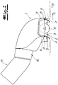
- the Fig. 1 shows a Glattêtstaubsaugerdüse invention in a view from below.
- the Glattêtstaubsaugerdüse has a nozzle body 1, which may be formed in a particularly simple manner, for example, as a one-piece injection molded part.
- a downwardly open suction chamber 2 is formed in the nozzle body 1.
- the suction chamber 2 has a rectangular base, so that the entire nozzle body 1 has a substantially bar shape.
- the suction chamber 2 is limited on the one hand along a working direction x by a front wall 3 and a rear wall 4 of the nozzle body 1 and to the walls 3, 4 connected flexible sealing strips 5 made of plastic, wherein the sealing strips 5 are divided by cuts 6 into segments 7.
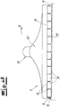
- the incisions 6 extend in the illustrated embodiment over the entire free height h of the flexible sealing strips 5, wherein the free height h of the sealing strips 5 may be for example between 5 mm and 20 mm.
- the sealing strips 5 are provided with a foot section 8 (FIG. Fig. 2 ) attached to the walls 3, 4 of the nozzle body 1, in particular by injection molding in the walls 3, 4 embedded.
- the foot sections 8 are not taken into account in the determination of the free height h.
- the sealing strips 5 may for example have between 6 and 30, in particular between 8 and 16 segments. In the exemplary embodiment, an embodiment with 12 segments is shown by way of example.
- a transverse direction y of the suction chamber 2 is bounded by side walls 9 of the nozzle body 1. Furthermore, the nozzle body 1 has a suction channel 10 opening into the suction chamber 2 for discharging a suction air stream flowing through the suction chamber 2, a pipe socket 11 being connected rotatably to the suction channel 10.
- the rotatable transition between the suction channel 10 and the pipe socket 11 is the only articulated connection of the smooth-bottom vacuum cleaner nozzle, whereby a simple design is supported.
- the support members 12 are according to the Fig. 1 each designed as a roller inserted into the suction chamber 2, but the invention is not limited to such a configuration.
- skids come into consideration as a support member 12, wherein the bearing surface seen in the working direction x is at least partially disposed between the front wall 3 and the rear wall 4, regardless of the specific configuration of the support elements 12.
- other variants are conceivable.
- smooth-floor vacuum cleaner nozzle By virtue of the smooth-floor vacuum cleaner nozzle according to the invention, a particularly good suction cleaning is achieved, on the one hand, on completely level, seamless, smooth floors and, on the other hand, on a smooth floor provided with joints.
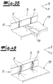
- the Fig. 3a shows the Glattêtstaubsaugerdüse invention on a provided with joints 14 bottom surface 13. Since the sealing strips 5 according to the Fig. 2 create joints outside the joints 14 sealingly to the bottom surface 13 and the segments 7 are only separated from each other by incisions 6 and in addition the suction chamber 2 is limited at its edges by the side walls 9, results in a very good seal the Glatt réellestaubsaugerdüse relative to the bottom surface 13, however, the joints 14 are available for the entry of suction air. Due to the good sealing and the controlled support of the nozzle body 1 by means of the support elements 12, the effective at the joints 14 suction air flow is maximized, why deep joints 14 can be cleaned very reliable and effective, which is particularly in the Fig. 3b is shown as an example.
- Fig. 4a and 4b correspond to the representations of Fig. 3a and 3b However, wherein the bottom surface 13 is completely flat and thus configured without joints 14.
- the sealing strips 5 would abut sealingly on the bottom surface 13 as described above, it would indeed be possible for the nozzle elements 1 to be prevented from seizing by the support elements 12, but no air flow necessary for the suction cleaning would be able to be provided on sealing strips 5.
- the sealing strips 5 are flexibly formed from plastic and additionally segmented in the context of the invention, the individual segments 7 can be deformed by increasing negative pressure in the suction chamber 2, which then results in openings for the passage of suction. In the context of the invention, therefore, a type of valve function is achieved, which always ensures a necessary for an effective suction volume flow of the suction air.
- the individual segments 7 according to the Fig. 2 completely raised and / or deformed at their edges (see in particular Fig. 4b ).
Landscapes
- Engineering & Computer Science (AREA)
- Mechanical Engineering (AREA)
- Nozzles For Electric Vacuum Cleaners (AREA)
Applications Claiming Priority (1)
| Application Number | Priority Date | Filing Date | Title |
|---|---|---|---|
| DE102017115299.7A DE102017115299A1 (de) | 2017-07-07 | 2017-07-07 | Glattbodenstaubsaugerdüse |
Publications (2)
| Publication Number | Publication Date |
|---|---|
| EP3430962A1 true EP3430962A1 (fr) | 2019-01-23 |
| EP3430962B1 EP3430962B1 (fr) | 2021-09-22 |
Family
ID=62567425
Family Applications (1)
| Application Number | Title | Priority Date | Filing Date |
|---|---|---|---|
| EP18176215.4A Active EP3430962B1 (fr) | 2017-07-07 | 2018-06-06 | Buse d'aspirateur pour surfaces lisses |
Country Status (3)
| Country | Link |
|---|---|
| EP (1) | EP3430962B1 (fr) |
| CN (1) | CN109199230B (fr) |
| DE (1) | DE102017115299A1 (fr) |
Families Citing this family (4)
| Publication number | Priority date | Publication date | Assignee | Title |
|---|---|---|---|---|
| CN112641375A (zh) * | 2020-05-21 | 2021-04-13 | 安徽大汉机器人集团有限公司 | 一种吸拖一体机 |
| CN112089361B (zh) * | 2020-09-17 | 2024-07-05 | 南京弘新锐科技有限公司 | 一种曲面自适应真空收集系统 |
| CN114271740A (zh) * | 2021-12-20 | 2022-04-05 | 添可智能科技有限公司 | 清洁设备及清洁方法 |
| WO2024050691A1 (fr) * | 2022-09-06 | 2024-03-14 | 周劲松 | Structure de brosse à plancher de dispositif de nettoyage de sol |
Citations (4)
| Publication number | Priority date | Publication date | Assignee | Title |
|---|---|---|---|---|
| US1849663A (en) * | 1928-12-26 | 1932-03-15 | Walter S Finnell | Vacuum floor mopper |
| US20140130295A1 (en) * | 2012-11-13 | 2014-05-15 | Robert S. Robinson | Wide-area vacuum/squeegee head floor cleaning tool |
| EP2939582A1 (fr) * | 2014-04-29 | 2015-11-04 | BSH Hausgeräte GmbH | Buse d'aspirateur |
| EP2989952A2 (fr) * | 2014-08-29 | 2016-03-02 | Samsung Electronics Co., Ltd. | Buse d'aspiration et aspirateur équipé de celui-ci |
Family Cites Families (14)
| Publication number | Priority date | Publication date | Assignee | Title |
|---|---|---|---|---|
| US4190924A (en) | 1977-10-11 | 1980-03-04 | Nicholson James A | Animal grooming device |
| US20050066471A1 (en) | 2003-09-30 | 2005-03-31 | Miller Paul R. | Color-coded cleaning nozzles and method of cleaning |
| DE102004005144A1 (de) | 2004-02-03 | 2005-08-18 | Vorwerk & Co. Interholding Gmbh | Bodendüse für einen Staubsauger |
| US7617564B2 (en) | 2005-10-05 | 2009-11-17 | Alto U.S. Inc. | Dual purpose floor cleaning apparatus and method of use |
| DE102008012889B4 (de) * | 2008-03-06 | 2012-04-19 | Wessel-Werk Gmbh | Saugdüse für Bodenstaubsauger |
| DE102008015904B4 (de) * | 2008-03-27 | 2013-01-17 | Wessel-Werk Gmbh | Saugdüse für Bodenstaubsauger |
| DE102014100004A1 (de) | 2014-01-02 | 2015-07-02 | Miele & Cie. Kg | Saugwerk für Staubsauger |
| CN203662686U (zh) * | 2014-01-13 | 2014-06-25 | 苏州爱普电器有限公司 | 立式真空吸尘器 |
| DE102014105809A1 (de) | 2014-04-24 | 2015-10-29 | Wessel-Werk Gmbh | Saugdüse zum Saugen von Glattböden, insbesondere von gefliesten Bodenflächen |
| CN204071949U (zh) * | 2014-05-16 | 2015-01-07 | 科沃斯机器人有限公司 | 吸尘器地刷及其吸尘器 |
| DE102014114030A1 (de) | 2014-09-26 | 2016-03-31 | Vorwerk & Co. Interholding Gmbh | Grobgutdichtlippen |
| DE102014116280A1 (de) | 2014-11-07 | 2016-05-12 | Vorwerk & Co. Interholding Gmbh | Saugdüse |
| DE102016103974B4 (de) * | 2015-03-06 | 2022-07-28 | Wessel-Werk Gmbh | Saugdüse für Bodenstaubsauger |
| DE102015105228B4 (de) * | 2015-04-07 | 2019-08-22 | Vorwerk & Co. Interholding Gmbh | Vorrichtung für ein ein saugendes Gebläse aufweisendes Reinigungsgerät |
-
2017
- 2017-07-07 DE DE102017115299.7A patent/DE102017115299A1/de not_active Withdrawn
-
2018
- 2018-06-06 EP EP18176215.4A patent/EP3430962B1/fr active Active
- 2018-07-06 CN CN201810733478.3A patent/CN109199230B/zh active Active
Patent Citations (4)
| Publication number | Priority date | Publication date | Assignee | Title |
|---|---|---|---|---|
| US1849663A (en) * | 1928-12-26 | 1932-03-15 | Walter S Finnell | Vacuum floor mopper |
| US20140130295A1 (en) * | 2012-11-13 | 2014-05-15 | Robert S. Robinson | Wide-area vacuum/squeegee head floor cleaning tool |
| EP2939582A1 (fr) * | 2014-04-29 | 2015-11-04 | BSH Hausgeräte GmbH | Buse d'aspirateur |
| EP2989952A2 (fr) * | 2014-08-29 | 2016-03-02 | Samsung Electronics Co., Ltd. | Buse d'aspiration et aspirateur équipé de celui-ci |
Also Published As
| Publication number | Publication date |
|---|---|
| DE102017115299A1 (de) | 2019-01-10 |
| CN109199230A (zh) | 2019-01-15 |
| CN109199230B (zh) | 2021-08-10 |
| EP3430962B1 (fr) | 2021-09-22 |
Similar Documents
| Publication | Publication Date | Title |
|---|---|---|
| EP2939582B1 (fr) | Buse d'aspirateur | |
| DE102014112141B4 (de) | Saugdüse für Bodenstaubsauger | |
| EP3430962B1 (fr) | Buse d'aspirateur pour surfaces lisses | |
| DE2846847C2 (de) | Staubsaugerdüse | |
| EP3047775B1 (fr) | Semelle en matiere synthetique pour une buse d'aspirateur | |
| EP0611544A1 (fr) | Buse en une pièce pour aspirateur | |
| EP2116165B1 (fr) | Bas d'aspiration pour aspirateurs | |
| DE2530126A1 (de) | Vorrichtung zum aufsaugen von trockenen oder feuchten verunreinigungen von einem boden | |
| DE102016115977A1 (de) | Bodenplatte für eine Saugdüse bzw. ein Vorsatzgerät | |
| EP2937029B1 (fr) | Buse d'aspiration destinée à aspirer des sols lisses, notamment des sols dallés | |
| EP3257417B1 (fr) | Buse d'aspirateur | |
| EP3025626A1 (fr) | Buse de sol pour un appareil d'entretien du sol et procede de fabrication d'une buse de sol pour un appareil d'entretien du sol | |
| EP0818173B1 (fr) | Suceur à triple fonction pour aspirateur | |
| EP1935307B1 (fr) | Buse de sol pour aspirateur | |
| EP3050475B1 (fr) | Buse d'aspiration pour surfaces dures | |
| DE102017118487B4 (de) | Saugdüse für ein ein Sauggebläse aufweisendes Reinigungsgerät | |
| EP3795047B1 (fr) | Suceur d'aspirateur universel | |
| EP3042597B1 (fr) | Buse de sol pour aspirateur | |
| DE102015105228B4 (de) | Vorrichtung für ein ein saugendes Gebläse aufweisendes Reinigungsgerät | |
| EP3760091A1 (fr) | Semelle de crosse, buse d'aspirateur et aspirateur | |
| DE102018126367A1 (de) | Staubsaugerbodendüse | |
| EP3298943B1 (fr) | Système de nettoyage par aspiration | |
| DE102015104436A1 (de) | Gleitsohle für eine Staubsaugerdüse | |
| DE102017114225A1 (de) | Staubsaugerdüse | |
| DE102015105415A1 (de) | Bodendüse für Staubsauger |
Legal Events
| Date | Code | Title | Description |
|---|---|---|---|
| PUAI | Public reference made under article 153(3) epc to a published international application that has entered the european phase |
Free format text: ORIGINAL CODE: 0009012 |
|
| STAA | Information on the status of an ep patent application or granted ep patent |
Free format text: STATUS: THE APPLICATION HAS BEEN PUBLISHED |
|
| AK | Designated contracting states |
Kind code of ref document: A1 Designated state(s): AL AT BE BG CH CY CZ DE DK EE ES FI FR GB GR HR HU IE IS IT LI LT LU LV MC MK MT NL NO PL PT RO RS SE SI SK SM TR |
|
| AX | Request for extension of the european patent |
Extension state: BA ME |
|
| STAA | Information on the status of an ep patent application or granted ep patent |
Free format text: STATUS: REQUEST FOR EXAMINATION WAS MADE |
|
| 17P | Request for examination filed |
Effective date: 20190130 |
|
| RBV | Designated contracting states (corrected) |
Designated state(s): AL AT BE BG CH CY CZ DE DK EE ES FI FR GB GR HR HU IE IS IT LI LT LU LV MC MK MT NL NO PL PT RO RS SE SI SK SM TR |
|
| GRAP | Despatch of communication of intention to grant a patent |
Free format text: ORIGINAL CODE: EPIDOSNIGR1 |
|
| STAA | Information on the status of an ep patent application or granted ep patent |
Free format text: STATUS: GRANT OF PATENT IS INTENDED |
|
| INTG | Intention to grant announced |
Effective date: 20210507 |
|
| GRAS | Grant fee paid |
Free format text: ORIGINAL CODE: EPIDOSNIGR3 |
|
| GRAA | (expected) grant |
Free format text: ORIGINAL CODE: 0009210 |
|
| STAA | Information on the status of an ep patent application or granted ep patent |
Free format text: STATUS: THE PATENT HAS BEEN GRANTED |
|
| AK | Designated contracting states |
Kind code of ref document: B1 Designated state(s): AL AT BE BG CH CY CZ DE DK EE ES FI FR GB GR HR HU IE IS IT LI LT LU LV MC MK MT NL NO PL PT RO RS SE SI SK SM TR |
|
| REG | Reference to a national code |
Ref country code: GB Ref legal event code: FG4D Free format text: NOT ENGLISH |
|
| REG | Reference to a national code |
Ref country code: DE Ref legal event code: R096 Ref document number: 502018007141 Country of ref document: DE |
|
| REG | Reference to a national code |
Ref country code: IE Ref legal event code: FG4D Free format text: LANGUAGE OF EP DOCUMENT: GERMAN |
|
| REG | Reference to a national code |
Ref country code: CH Ref legal event code: EP Ref country code: AT Ref legal event code: REF Ref document number: 1431650 Country of ref document: AT Kind code of ref document: T Effective date: 20211015 |
|
| REG | Reference to a national code |
Ref country code: LT Ref legal event code: MG9D |
|
| REG | Reference to a national code |
Ref country code: NL Ref legal event code: MP Effective date: 20210922 |
|
| PG25 | Lapsed in a contracting state [announced via postgrant information from national office to epo] |
Ref country code: RS Free format text: LAPSE BECAUSE OF FAILURE TO SUBMIT A TRANSLATION OF THE DESCRIPTION OR TO PAY THE FEE WITHIN THE PRESCRIBED TIME-LIMIT Effective date: 20210922 Ref country code: SE Free format text: LAPSE BECAUSE OF FAILURE TO SUBMIT A TRANSLATION OF THE DESCRIPTION OR TO PAY THE FEE WITHIN THE PRESCRIBED TIME-LIMIT Effective date: 20210922 Ref country code: HR Free format text: LAPSE BECAUSE OF FAILURE TO SUBMIT A TRANSLATION OF THE DESCRIPTION OR TO PAY THE FEE WITHIN THE PRESCRIBED TIME-LIMIT Effective date: 20210922 Ref country code: FI Free format text: LAPSE BECAUSE OF FAILURE TO SUBMIT A TRANSLATION OF THE DESCRIPTION OR TO PAY THE FEE WITHIN THE PRESCRIBED TIME-LIMIT Effective date: 20210922 Ref country code: BG Free format text: LAPSE BECAUSE OF FAILURE TO SUBMIT A TRANSLATION OF THE DESCRIPTION OR TO PAY THE FEE WITHIN THE PRESCRIBED TIME-LIMIT Effective date: 20211222 Ref country code: LT Free format text: LAPSE BECAUSE OF FAILURE TO SUBMIT A TRANSLATION OF THE DESCRIPTION OR TO PAY THE FEE WITHIN THE PRESCRIBED TIME-LIMIT Effective date: 20210922 Ref country code: NO Free format text: LAPSE BECAUSE OF FAILURE TO SUBMIT A TRANSLATION OF THE DESCRIPTION OR TO PAY THE FEE WITHIN THE PRESCRIBED TIME-LIMIT Effective date: 20211222 |
|
| PG25 | Lapsed in a contracting state [announced via postgrant information from national office to epo] |
Ref country code: LV Free format text: LAPSE BECAUSE OF FAILURE TO SUBMIT A TRANSLATION OF THE DESCRIPTION OR TO PAY THE FEE WITHIN THE PRESCRIBED TIME-LIMIT Effective date: 20210922 Ref country code: GR Free format text: LAPSE BECAUSE OF FAILURE TO SUBMIT A TRANSLATION OF THE DESCRIPTION OR TO PAY THE FEE WITHIN THE PRESCRIBED TIME-LIMIT Effective date: 20211223 |
|
| PG25 | Lapsed in a contracting state [announced via postgrant information from national office to epo] |
Ref country code: IS Free format text: LAPSE BECAUSE OF FAILURE TO SUBMIT A TRANSLATION OF THE DESCRIPTION OR TO PAY THE FEE WITHIN THE PRESCRIBED TIME-LIMIT Effective date: 20220122 Ref country code: SK Free format text: LAPSE BECAUSE OF FAILURE TO SUBMIT A TRANSLATION OF THE DESCRIPTION OR TO PAY THE FEE WITHIN THE PRESCRIBED TIME-LIMIT Effective date: 20210922 Ref country code: RO Free format text: LAPSE BECAUSE OF FAILURE TO SUBMIT A TRANSLATION OF THE DESCRIPTION OR TO PAY THE FEE WITHIN THE PRESCRIBED TIME-LIMIT Effective date: 20210922 Ref country code: PT Free format text: LAPSE BECAUSE OF FAILURE TO SUBMIT A TRANSLATION OF THE DESCRIPTION OR TO PAY THE FEE WITHIN THE PRESCRIBED TIME-LIMIT Effective date: 20220124 Ref country code: PL Free format text: LAPSE BECAUSE OF FAILURE TO SUBMIT A TRANSLATION OF THE DESCRIPTION OR TO PAY THE FEE WITHIN THE PRESCRIBED TIME-LIMIT Effective date: 20210922 Ref country code: NL Free format text: LAPSE BECAUSE OF FAILURE TO SUBMIT A TRANSLATION OF THE DESCRIPTION OR TO PAY THE FEE WITHIN THE PRESCRIBED TIME-LIMIT Effective date: 20210922 Ref country code: ES Free format text: LAPSE BECAUSE OF FAILURE TO SUBMIT A TRANSLATION OF THE DESCRIPTION OR TO PAY THE FEE WITHIN THE PRESCRIBED TIME-LIMIT Effective date: 20210922 Ref country code: EE Free format text: LAPSE BECAUSE OF FAILURE TO SUBMIT A TRANSLATION OF THE DESCRIPTION OR TO PAY THE FEE WITHIN THE PRESCRIBED TIME-LIMIT Effective date: 20210922 Ref country code: CZ Free format text: LAPSE BECAUSE OF FAILURE TO SUBMIT A TRANSLATION OF THE DESCRIPTION OR TO PAY THE FEE WITHIN THE PRESCRIBED TIME-LIMIT Effective date: 20210922 Ref country code: AL Free format text: LAPSE BECAUSE OF FAILURE TO SUBMIT A TRANSLATION OF THE DESCRIPTION OR TO PAY THE FEE WITHIN THE PRESCRIBED TIME-LIMIT Effective date: 20210922 |
|
| REG | Reference to a national code |
Ref country code: DE Ref legal event code: R097 Ref document number: 502018007141 Country of ref document: DE |
|
| PG25 | Lapsed in a contracting state [announced via postgrant information from national office to epo] |
Ref country code: DK Free format text: LAPSE BECAUSE OF FAILURE TO SUBMIT A TRANSLATION OF THE DESCRIPTION OR TO PAY THE FEE WITHIN THE PRESCRIBED TIME-LIMIT Effective date: 20210922 |
|
| PLBE | No opposition filed within time limit |
Free format text: ORIGINAL CODE: 0009261 |
|
| STAA | Information on the status of an ep patent application or granted ep patent |
Free format text: STATUS: NO OPPOSITION FILED WITHIN TIME LIMIT |
|
| 26N | No opposition filed |
Effective date: 20220623 |
|
| PG25 | Lapsed in a contracting state [announced via postgrant information from national office to epo] |
Ref country code: SI Free format text: LAPSE BECAUSE OF FAILURE TO SUBMIT A TRANSLATION OF THE DESCRIPTION OR TO PAY THE FEE WITHIN THE PRESCRIBED TIME-LIMIT Effective date: 20210922 |
|
| PG25 | Lapsed in a contracting state [announced via postgrant information from national office to epo] |
Ref country code: MC Free format text: LAPSE BECAUSE OF FAILURE TO SUBMIT A TRANSLATION OF THE DESCRIPTION OR TO PAY THE FEE WITHIN THE PRESCRIBED TIME-LIMIT Effective date: 20210922 Ref country code: IT Free format text: LAPSE BECAUSE OF FAILURE TO SUBMIT A TRANSLATION OF THE DESCRIPTION OR TO PAY THE FEE WITHIN THE PRESCRIBED TIME-LIMIT Effective date: 20210922 |
|
| REG | Reference to a national code |
Ref country code: CH Ref legal event code: PL |
|
| REG | Reference to a national code |
Ref country code: BE Ref legal event code: MM Effective date: 20220630 |
|
| PG25 | Lapsed in a contracting state [announced via postgrant information from national office to epo] |
Ref country code: LU Free format text: LAPSE BECAUSE OF NON-PAYMENT OF DUE FEES Effective date: 20220606 Ref country code: LI Free format text: LAPSE BECAUSE OF NON-PAYMENT OF DUE FEES Effective date: 20220630 Ref country code: IE Free format text: LAPSE BECAUSE OF NON-PAYMENT OF DUE FEES Effective date: 20220606 Ref country code: CH Free format text: LAPSE BECAUSE OF NON-PAYMENT OF DUE FEES Effective date: 20220630 |
|
| PG25 | Lapsed in a contracting state [announced via postgrant information from national office to epo] |
Ref country code: BE Free format text: LAPSE BECAUSE OF NON-PAYMENT OF DUE FEES Effective date: 20220630 |
|
| PG25 | Lapsed in a contracting state [announced via postgrant information from national office to epo] |
Ref country code: HU Free format text: LAPSE BECAUSE OF FAILURE TO SUBMIT A TRANSLATION OF THE DESCRIPTION OR TO PAY THE FEE WITHIN THE PRESCRIBED TIME-LIMIT; INVALID AB INITIO Effective date: 20180606 |
|
| PG25 | Lapsed in a contracting state [announced via postgrant information from national office to epo] |
Ref country code: SM Free format text: LAPSE BECAUSE OF FAILURE TO SUBMIT A TRANSLATION OF THE DESCRIPTION OR TO PAY THE FEE WITHIN THE PRESCRIBED TIME-LIMIT Effective date: 20210922 Ref country code: MK Free format text: LAPSE BECAUSE OF FAILURE TO SUBMIT A TRANSLATION OF THE DESCRIPTION OR TO PAY THE FEE WITHIN THE PRESCRIBED TIME-LIMIT Effective date: 20210922 Ref country code: CY Free format text: LAPSE BECAUSE OF FAILURE TO SUBMIT A TRANSLATION OF THE DESCRIPTION OR TO PAY THE FEE WITHIN THE PRESCRIBED TIME-LIMIT Effective date: 20210922 |
|
| PGFP | Annual fee paid to national office [announced via postgrant information from national office to epo] |
Ref country code: GB Payment date: 20240621 Year of fee payment: 7 |
|
| PGFP | Annual fee paid to national office [announced via postgrant information from national office to epo] |
Ref country code: DE Payment date: 20240521 Year of fee payment: 7 |
|
| PGFP | Annual fee paid to national office [announced via postgrant information from national office to epo] |
Ref country code: FR Payment date: 20240628 Year of fee payment: 7 |
|
| REG | Reference to a national code |
Ref country code: AT Ref legal event code: MM01 Ref document number: 1431650 Country of ref document: AT Kind code of ref document: T Effective date: 20230606 |
|
| PGFP | Annual fee paid to national office [announced via postgrant information from national office to epo] |
Ref country code: TR Payment date: 20240527 Year of fee payment: 7 |
|
| PG25 | Lapsed in a contracting state [announced via postgrant information from national office to epo] |
Ref country code: MT Free format text: LAPSE BECAUSE OF FAILURE TO SUBMIT A TRANSLATION OF THE DESCRIPTION OR TO PAY THE FEE WITHIN THE PRESCRIBED TIME-LIMIT Effective date: 20210922 |
|
| PG25 | Lapsed in a contracting state [announced via postgrant information from national office to epo] |
Ref country code: AT Free format text: LAPSE BECAUSE OF NON-PAYMENT OF DUE FEES Effective date: 20230606 |
|
| PG25 | Lapsed in a contracting state [announced via postgrant information from national office to epo] |
Ref country code: AT Free format text: LAPSE BECAUSE OF NON-PAYMENT OF DUE FEES Effective date: 20230606 |
|
| REG | Reference to a national code |
Ref country code: DE Ref legal event code: R119 Ref document number: 502018007141 Country of ref document: DE |
|
| GBPC | Gb: european patent ceased through non-payment of renewal fee |
Effective date: 20250606 |
|
| PG25 | Lapsed in a contracting state [announced via postgrant information from national office to epo] |
Ref country code: GB Free format text: LAPSE BECAUSE OF NON-PAYMENT OF DUE FEES Effective date: 20250606 |
|
| PG25 | Lapsed in a contracting state [announced via postgrant information from national office to epo] |
Ref country code: DE Free format text: LAPSE BECAUSE OF NON-PAYMENT OF DUE FEES Effective date: 20260101 |
|
| PGFP | Annual fee paid to national office [announced via postgrant information from national office to epo] |
Ref country code: AT Payment date: 20260410 Year of fee payment: 5 |
|
| PG25 | Lapsed in a contracting state [announced via postgrant information from national office to epo] |
Ref country code: FR Free format text: LAPSE BECAUSE OF NON-PAYMENT OF DUE FEES Effective date: 20250630 |