EP3430996A1 - Cathéter à électrodes réparties en fibonacci - Google Patents
Cathéter à électrodes réparties en fibonacci Download PDFInfo
- Publication number
- EP3430996A1 EP3430996A1 EP18183654.5A EP18183654A EP3430996A1 EP 3430996 A1 EP3430996 A1 EP 3430996A1 EP 18183654 A EP18183654 A EP 18183654A EP 3430996 A1 EP3430996 A1 EP 3430996A1
- Authority
- EP
- European Patent Office
- Prior art keywords
- splines
- catheter
- electrodes
- catheter according
- disposed
- Prior art date
- Legal status (The legal status is an assumption and is not a legal conclusion. Google has not performed a legal analysis and makes no representation as to the accuracy of the status listed.)
- Granted
Links
- 238000013507 mapping Methods 0.000 claims abstract description 23
- WABPQHHGFIMREM-UHFFFAOYSA-N lead(0) Chemical compound [Pb] WABPQHHGFIMREM-UHFFFAOYSA-N 0.000 claims abstract description 8
- 210000002216 heart Anatomy 0.000 description 30
- 238000000034 method Methods 0.000 description 26
- 230000004913 activation Effects 0.000 description 14
- 239000013598 vector Substances 0.000 description 13
- 238000010586 diagram Methods 0.000 description 12
- 230000000694 effects Effects 0.000 description 8
- 238000002679 ablation Methods 0.000 description 7
- 238000010276 construction Methods 0.000 description 7
- 210000005242 cardiac chamber Anatomy 0.000 description 6
- 230000006870 function Effects 0.000 description 5
- 210000001519 tissue Anatomy 0.000 description 5
- 239000000463 material Substances 0.000 description 4
- 206010003658 Atrial Fibrillation Diseases 0.000 description 3
- 239000004642 Polyimide Substances 0.000 description 3
- 230000002159 abnormal effect Effects 0.000 description 3
- 206010003119 arrhythmia Diseases 0.000 description 3
- 238000004364 calculation method Methods 0.000 description 3
- 230000007547 defect Effects 0.000 description 3
- 210000005003 heart tissue Anatomy 0.000 description 3
- 230000033001 locomotion Effects 0.000 description 3
- 229920001721 polyimide Polymers 0.000 description 3
- 238000012545 processing Methods 0.000 description 3
- 229920002614 Polyether block amide Polymers 0.000 description 2
- 230000000747 cardiac effect Effects 0.000 description 2
- 229910003460 diamond Inorganic materials 0.000 description 2
- 239000010432 diamond Substances 0.000 description 2
- 210000001174 endocardium Anatomy 0.000 description 2
- 210000004165 myocardium Anatomy 0.000 description 2
- 229910001000 nickel titanium Inorganic materials 0.000 description 2
- 239000004033 plastic Substances 0.000 description 2
- 229920003023 plastic Polymers 0.000 description 2
- 229920002635 polyurethane Polymers 0.000 description 2
- 239000004814 polyurethane Substances 0.000 description 2
- 230000002792 vascular Effects 0.000 description 2
- 230000002861 ventricular Effects 0.000 description 2
- 206010001497 Agitation Diseases 0.000 description 1
- 101100182248 Caenorhabditis elegans lat-2 gene Proteins 0.000 description 1
- 230000005856 abnormality Effects 0.000 description 1
- 230000009471 action Effects 0.000 description 1
- 238000013459 approach Methods 0.000 description 1
- 230000006793 arrhythmia Effects 0.000 description 1
- 230000000712 assembly Effects 0.000 description 1
- 238000000429 assembly Methods 0.000 description 1
- 206010003668 atrial tachycardia Diseases 0.000 description 1
- 230000008859 change Effects 0.000 description 1
- 239000011248 coating agent Substances 0.000 description 1
- 238000000576 coating method Methods 0.000 description 1
- 239000013065 commercial product Substances 0.000 description 1
- 238000004590 computer program Methods 0.000 description 1
- 239000004020 conductor Substances 0.000 description 1
- 238000002405 diagnostic procedure Methods 0.000 description 1
- 238000011156 evaluation Methods 0.000 description 1
- 210000002837 heart atrium Anatomy 0.000 description 1
- 238000010438 heat treatment Methods 0.000 description 1
- 238000003384 imaging method Methods 0.000 description 1
- 230000001771 impaired effect Effects 0.000 description 1
- 230000003902 lesion Effects 0.000 description 1
- 239000002184 metal Substances 0.000 description 1
- 229910052751 metal Inorganic materials 0.000 description 1
- 238000012986 modification Methods 0.000 description 1
- 230000004048 modification Effects 0.000 description 1
- 238000012544 monitoring process Methods 0.000 description 1
- HLXZNVUGXRDIFK-UHFFFAOYSA-N nickel titanium Chemical compound [Ti].[Ti].[Ti].[Ti].[Ti].[Ti].[Ti].[Ti].[Ti].[Ti].[Ti].[Ni].[Ni].[Ni].[Ni].[Ni].[Ni].[Ni].[Ni].[Ni].[Ni].[Ni].[Ni].[Ni].[Ni] HLXZNVUGXRDIFK-UHFFFAOYSA-N 0.000 description 1
- 230000037361 pathway Effects 0.000 description 1
- 230000008569 process Effects 0.000 description 1
- 210000003492 pulmonary vein Anatomy 0.000 description 1
- 230000033764 rhythmic process Effects 0.000 description 1
- 239000010935 stainless steel Substances 0.000 description 1
- 229910001220 stainless steel Inorganic materials 0.000 description 1
- 239000000126 substance Substances 0.000 description 1
- 230000001225 therapeutic effect Effects 0.000 description 1
- 238000002560 therapeutic procedure Methods 0.000 description 1
- 238000002604 ultrasonography Methods 0.000 description 1
- 208000003663 ventricular fibrillation Diseases 0.000 description 1
- 206010047302 ventricular tachycardia Diseases 0.000 description 1
Images


Classifications
-
- A—HUMAN NECESSITIES
- A61—MEDICAL OR VETERINARY SCIENCE; HYGIENE
- A61B—DIAGNOSIS; SURGERY; IDENTIFICATION
- A61B18/00—Surgical instruments, devices or methods for transferring non-mechanical forms of energy to or from the body
- A61B18/04—Surgical instruments, devices or methods for transferring non-mechanical forms of energy to or from the body by heating
- A61B18/12—Surgical instruments, devices or methods for transferring non-mechanical forms of energy to or from the body by heating by passing a current through the tissue to be heated, e.g. high-frequency current
- A61B18/14—Probes or electrodes therefor
- A61B18/1492—Probes or electrodes therefor having a flexible, catheter-like structure, e.g. for heart ablation
-
- A—HUMAN NECESSITIES
- A61—MEDICAL OR VETERINARY SCIENCE; HYGIENE
- A61B—DIAGNOSIS; SURGERY; IDENTIFICATION
- A61B5/00—Measuring for diagnostic purposes; Identification of persons
- A61B5/24—Detecting, measuring or recording bioelectric or biomagnetic signals of the body or parts thereof
- A61B5/25—Bioelectric electrodes therefor
- A61B5/279—Bioelectric electrodes therefor specially adapted for particular uses
- A61B5/28—Bioelectric electrodes therefor specially adapted for particular uses for electrocardiography [ECG]
- A61B5/283—Invasive
- A61B5/287—Holders for multiple electrodes, e.g. electrode catheters for electrophysiological study [EPS]
-
- A—HUMAN NECESSITIES
- A61—MEDICAL OR VETERINARY SCIENCE; HYGIENE
- A61B—DIAGNOSIS; SURGERY; IDENTIFICATION
- A61B5/00—Measuring for diagnostic purposes; Identification of persons
- A61B5/68—Arrangements of detecting, measuring or recording means, e.g. sensors, in relation to patient
- A61B5/6846—Arrangements of detecting, measuring or recording means, e.g. sensors, in relation to patient specially adapted to be brought in contact with an internal body part, i.e. invasive
- A61B5/6847—Arrangements of detecting, measuring or recording means, e.g. sensors, in relation to patient specially adapted to be brought in contact with an internal body part, i.e. invasive mounted on an invasive device
- A61B5/6852—Catheters
- A61B5/6858—Catheters with a distal basket, e.g. expandable basket
-
- A—HUMAN NECESSITIES
- A61—MEDICAL OR VETERINARY SCIENCE; HYGIENE
- A61B—DIAGNOSIS; SURGERY; IDENTIFICATION
- A61B5/00—Measuring for diagnostic purposes; Identification of persons
- A61B5/68—Arrangements of detecting, measuring or recording means, e.g. sensors, in relation to patient
- A61B5/6846—Arrangements of detecting, measuring or recording means, e.g. sensors, in relation to patient specially adapted to be brought in contact with an internal body part, i.e. invasive
- A61B5/6847—Arrangements of detecting, measuring or recording means, e.g. sensors, in relation to patient specially adapted to be brought in contact with an internal body part, i.e. invasive mounted on an invasive device
- A61B5/6852—Catheters
- A61B5/6859—Catheters with multiple distal splines
-
- A—HUMAN NECESSITIES
- A61—MEDICAL OR VETERINARY SCIENCE; HYGIENE
- A61M—DEVICES FOR INTRODUCING MEDIA INTO, OR ONTO, THE BODY; DEVICES FOR TRANSDUCING BODY MEDIA OR FOR TAKING MEDIA FROM THE BODY; DEVICES FOR PRODUCING OR ENDING SLEEP OR STUPOR
- A61M25/00—Catheters; Hollow probes
- A61M25/0067—Catheters; Hollow probes characterised by the distal end, e.g. tips
- A61M25/0074—Dynamic characteristics of the catheter tip, e.g. openable, closable, expandable or deformable
-
- A—HUMAN NECESSITIES
- A61—MEDICAL OR VETERINARY SCIENCE; HYGIENE
- A61B—DIAGNOSIS; SURGERY; IDENTIFICATION
- A61B18/00—Surgical instruments, devices or methods for transferring non-mechanical forms of energy to or from the body
- A61B2018/00315—Surgical instruments, devices or methods for transferring non-mechanical forms of energy to or from the body for treatment of particular body parts
- A61B2018/00345—Vascular system
- A61B2018/00351—Heart
-
- A—HUMAN NECESSITIES
- A61—MEDICAL OR VETERINARY SCIENCE; HYGIENE
- A61B—DIAGNOSIS; SURGERY; IDENTIFICATION
- A61B18/00—Surgical instruments, devices or methods for transferring non-mechanical forms of energy to or from the body
- A61B2018/00636—Sensing and controlling the application of energy
- A61B2018/00773—Sensed parameters
- A61B2018/00839—Bioelectrical parameters, e.g. ECG, EEG
-
- A—HUMAN NECESSITIES
- A61—MEDICAL OR VETERINARY SCIENCE; HYGIENE
- A61B—DIAGNOSIS; SURGERY; IDENTIFICATION
- A61B2562/00—Details of sensors; Constructional details of sensor housings or probes; Accessories for sensors
- A61B2562/02—Details of sensors specially adapted for in-vivo measurements
- A61B2562/0209—Special features of electrodes classified in A61B5/24, A61B5/25, A61B5/283, A61B5/291, A61B5/296, A61B5/053
-
- A—HUMAN NECESSITIES
- A61—MEDICAL OR VETERINARY SCIENCE; HYGIENE
- A61B—DIAGNOSIS; SURGERY; IDENTIFICATION
- A61B2562/00—Details of sensors; Constructional details of sensor housings or probes; Accessories for sensors
- A61B2562/04—Arrangements of multiple sensors of the same type
- A61B2562/046—Arrangements of multiple sensors of the same type in a matrix array
-
- A—HUMAN NECESSITIES
- A61—MEDICAL OR VETERINARY SCIENCE; HYGIENE
- A61B—DIAGNOSIS; SURGERY; IDENTIFICATION
- A61B5/00—Measuring for diagnostic purposes; Identification of persons
- A61B5/68—Arrangements of detecting, measuring or recording means, e.g. sensors, in relation to patient
- A61B5/6846—Arrangements of detecting, measuring or recording means, e.g. sensors, in relation to patient specially adapted to be brought in contact with an internal body part, i.e. invasive
- A61B5/6847—Arrangements of detecting, measuring or recording means, e.g. sensors, in relation to patient specially adapted to be brought in contact with an internal body part, i.e. invasive mounted on an invasive device
- A61B5/6852—Catheters
- A61B5/6853—Catheters with a balloon
Definitions
- This invention relates to detecting, measuring or recording bioelectric signals of the body. More particularly, this invention relates to analysis of electrical signals of the heart for diagnostic purposes.
- Cardiac arrhythmias such as atrial fibrillation are an important cause of morbidity and death.
- U.S. Pat. No. 5,546,951 and U.S. Pat. No. 6,690,963, both issued to Ben Haim
- PCT application WO 96/05768 all of which are incorporated herein by reference, disclose methods for sensing an electrical property of heart tissue, for example, local activation time, as a function of the precise location within the heart. Data are acquired with one or more catheters having electrical and location sensors in their distal tips, which are advanced into the heart. Methods of creating a map of the electrical activity of the heart based on these data are disclosed in commonly assigned U.S. Pat. No. 6,226,542 , and U.S. Pat. No. 6,301,496, both issued to Reisfeld , which are incorporated herein by reference.
- location and electrical activity are typically initially measured on about 10 to about 20 points on the interior surface of the heart. These data points are then generally sufficient to generate a preliminary reconstruction or map of the cardiac surface.
- the preliminary map is often combined with data taken at additional points in order to generate a more comprehensive map of the heart's electrical activity. Indeed, in clinical settings, it is not uncommon to accumulate data at 100 or more sites to generate a detailed, comprehensive map of heart chamber electrical activity. The generated detailed map may then serve as the basis for deciding on a therapeutic course of action, for example, tissue ablation, to alter the propagation of the heart's electrical activity and to restore normal heart rhythm.
- Activation time differs from point to point in the endocardium due to the time required for conduction of electrical impulses through the heart muscle.
- the direction of this electrical conduction at any point in the heart is conventionally represented by an activation vector, which is normal to an isoelectric activation front, both of which may be derived from a map of activation time.
- the rate of propagation of the activation front through any point in the endocardium may be represented as a velocity vector.
- the trajectory of points on the cardiac surface may be used to infer motion characteristics such as the contractility of the tissue.
- maps depicting such motion characteristics may be constructed when the trajectory information is sampled at a sufficient number of points in the heart.
- Mapping the activation front and conduction fields aids the physician in identifying and diagnosing abnormalities, such as ventricular and atrial tachycardia and ventricular and atrial fibrillation, which result from areas of impaired electrical propagation in the heart tissue.
- Localized defects in the heart's conduction of activation signals may be identified by observing phenomena such as multiple activation fronts, abnormal concentrations of activation vectors, or changes in the velocity vector or deviation of the vector from normal values. Examples of such defects include re-entrant areas, which may be associated with signal patterns known as complex fractionated electrograms. Once a defect is located by such mapping, it may be ablated (if it is functioning abnormally) or otherwise treated to restore the normal function of the heart insofar as is possible.
- Electrical activity at a point in the heart is typically measured by advancing a catheter containing an electrical sensor at or near its distal tip to that point in the heart, contacting the tissue with the sensor and acquiring data at that point.
- One drawback with mapping a cardiac chamber using a catheter containing only a single, distal tip electrode is the long period of time required to accumulate data on a point-by-point basis over the requisite number of points required for a detailed map of the chamber as a whole.
- multiple-electrode catheters have been developed to simultaneously measure electrical activity, such as local activation times (LAT) at multiple sampled points in the heart chamber.
- LAT local activation times
- two electrodes are positioned at the point in the heart chamber at a known distance from each other, and the time difference between the occurrence of the electropotential at each electrode is measured. The speed of propagation is then simply the distance/time.
- this method requires that the line joining the two electrodes corresponds to the direction of travel of the electropotential, and this direction may not be known.
- Embodiments of the invention use a catheter with multiple electrodes.
- the catheter may be a two dimensional catheter, such as a PentaRayTM catheter with multiple splines, or a three-dimensional catheter such as a balloon or basket catheter.
- the catheter has a central electrode, which may be positioned on a selected point.
- the spatial distribution of the electrodes surrounding the central electrode is set to correspond to a Fibonacci array, and the electrodes are then placed on splines (for the two-dimensional catheter) or a balloon/basket for the three-dimensional catheter.
- the inventors have noticed that electrodes distributed on splines configured as Fibonacci spirals have the property that certain triangles defined by the electrodes are approximately equilateral.
- the value of the conduction velocity of the electropotential can be determined, and the accuracy of the determination is approximately invariant regardless of the direction of the propagation of the electropotential. Typically this is done within about 2.0 mm of the central electrode. However the neighborhood can be from 0.5 to 3.0 mm.
- a catheter having at least one lumen extending longitudinally therethrough and a mapping assembly having a plurality of splines mounted at the distal portion of the catheter body.
- Each of the splines has a proximal end disposed at the distal portion of the catheter body and a distal end and configured as a Fibonacci spiral arm that diverges outwardly from the proximal end.
- the splines each have a support arm with shape memory, a non-conductive covering in surrounding relation to the support arm, at least one location sensor mounted at or near the distal end, a plurality of electrodes mounted in surrounding relation to the non-conductive covering, and a plurality of electrode lead wires extending within the non-conductive covering. Each electrode lead wire is attached to a corresponding one of the electrodes.
- the electrodes are disposed at distances from the proximal end of the respective splines that correspond to a Fibonacci sequence.
- the splines further comprise a tip electrode mounted at or near the respective distal end thereof, electrically isolated from the support arm.
- the mapping assembly is moveable between an expanded arrangement, in which each of the splines extends radially outward from the catheter body, and a collapsed arrangement, in which each of the splines is disposed generally along a longitudinal axis of the catheter body.
- the splines are disposed on an expandable balloon, and the distal ends thereof bend in the expanded arrangement and converge at a central point.
- the splines comprise a first set of spiral arms having a left-directed curvature and a second set of spiral arms having a right-directed curvature that intersect the first set of spiral arms.
- the distal ends of the splines converge at a central point in the expanded arrangement to define a basket.
- a tip electrode is disposed at the central point.
- the mapping assembly has eight splines.
- the mapping assembly has 12 splines.
- a group of electrodes of neighboring splines are disposed so as to define approximately equilateral triangles, wherein a deviation from equilaterality of the triangles does not exceed 20%.
- a method which is carried out by introducing a catheter into a heart to be mapped.
- the catheter has at least one lumen extending longitudinally therethrough and a mapping assembly having a plurality of splines mounted at the distal portion of the catheter body.
- Each of the splines has a proximal end disposed at the distal portion of the catheter body and a distal end and configured as a Fibonacci spiral arm that diverges outwardly from the proximal end.
- the splines each have a support arm with shape memory, a non-conductive covering in surrounding relation to the support arm, at least one location sensor mounted at or near the distal end, a plurality of electrodes mounted in surrounding relation to the non-conductive covering, and a plurality of electrode lead wires extending within the non-conductive covering.
- Each electrode lead wire is attached to a corresponding one of the electrodes. The method is further carried out by positioning the mapping assembly so that at least one electrode from each spine is in contact with a respective location in the heart, and recording respective electrical data from the at least one electrode.
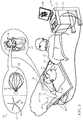
- Fig. 1 is a pictorial illustration of a system 10 for performing diagnostic and therapeutic procedures on a heart 12 of a living subject, which is constructed and operative in accordance with a disclosed embodiment of the invention.
- the system comprises a catheter 14, which is percutaneously inserted by an operator 16 through the patient's vascular system into a chamber or vascular structure of the heart 12.
- the operator 16 who is typically a physician, brings the catheter's distal tip 18 into contact with the heart wall, for example, at an ablation target site.
- Electrical activation maps may be prepared, according to the methods disclosed in U.S. Patent Nos. 6,226,542 , and 6,301,496 , and in commonly assigned U.S. Patent No. 6,892,091 , whose disclosures are herein incorporated by reference.
- the system 10 may comprise a general purpose or embedded computer processor, which is programmed with suitable software for carrying out the functions described hereinbelow.
- portions of the system 10 shown in other drawing figures herein are shown as comprising a number of separate functional blocks, these blocks are not necessarily separate physical entities, but rather may represent, for example, different computing tasks or data objects stored in a memory that is accessible to the processor. These tasks may be carried out in software running on a single processor, or on multiple processors.
- the software may be provided to the processor or processors on tangible non-transitory media, such as CD-ROM or non-volatile memory.
- the system 10 may comprise a digital signal processor or hard-wired logic.
- CARTO® 3 System available from Biosense Webster, Inc., 3333 Diamond Canyon Road, Diamond Bar, CA 91765. This system may be modified by those skilled in the art to embody the principles of the invention described herein.
- Areas determined to be abnormal can be ablated by application of thermal energy, e.g., by passage of radiofrequency electrical current through wires in the catheter to one or more electrodes at the distal tip 18, which apply the radiofrequency energy to the myocardium.
- the energy is absorbed in the tissue, heating it to a point (typically above 50°C) at which it permanently loses its electrical excitability.
- this procedure creates non-conducting lesions in the cardiac tissue, which disrupt the abnormal electrical pathway causing the arrhythmia.
- the principles of the invention can be applied to different heart chambers to diagnose and treat many different cardiac arrhythmias.
- the catheter 14 typically comprises a handle 20, having suitable controls on the handle to enable the operator 16 to steer, position and orient the distal end of the catheter as desired for the ablation.
- the distal portion of the catheter 14 contains position sensors (not shown) that provide signals to a processor 22, located in a console 24.
- the processor 22 may fulfill several processing functions as described below.
- the catheter 14 is a multi-electrode catheter, which can be a balloon or basket catheter as shown in the right portion of balloon 37, or a spline catheter as shown in the left portion.
- multiple electrodes 32 which are used as sensing electrodes and have known locations on the basket or spline, and known relationships to one another.
- the catheter is located in the heart, for example by constructing a current position map, the location of each of the electrodes 32 in the heart is known.
- One method for generation of a current position map is described in commonly assigned U.S. Patent No. 8,478,383 to Bar-Tal et al. , which is herein incorporated by reference.
- Electrodes 32 located at or near the distal tip 18 of the catheter 14 via cable 34 to the console 24.
- Pacing signals and other control signals may be conveyed from the console 24 through the cable 34 and the electrodes 32 to the heart 12.
- Wire connections 35 link the console 24 with body surface electrodes 30 and other components of a positioning sub-system for measuring location and orientation coordinates of the catheter 14.
- the processor 22, or another processor may be an element of the positioning subsystem.
- the electrodes 32 and the body surface electrodes 30 may be used to measure tissue impedance at the ablation site as taught in U.S. Patent No. 7,536,218, issued to Govari et al. , which is herein incorporated by reference.
- a temperature sensor (not shown), typically a thermocouple or thermistor, may be mounted near the distal tip 18 of the catheter 14.
- the console 24 typically contains one or more ablation power generators 25.
- the catheter 14 may be adapted to conduct ablative energy to the heart using any known ablation technique, e.g., radiofrequency energy, ultrasound energy, and laser-produced light energy. Such methods are disclosed in commonly assigned U.S. Patent Nos. 6,814,733 , 6,997,924 , and 7,156,816 , which are herein incorporated by reference.
- the positioning subsystem comprises a magnetic position tracking arrangement that determines the position and orientation of the catheter 14 by generating magnetic fields in a predefined working volume and sensing these fields at the catheter, using field generating coils 28.
- a suitable positioning subsystem is described in U.S. Patent No. 7,756,576 , which is hereby incorporated by reference, and in the above-noted U.S. Patent No. 7,536,218 .
- the catheter 14 is coupled to the console 24, which enables the operator 16 to observe and regulate the functions of the catheter 14.
- Console 24 includes a processor, preferably a computer with appropriate signal processing circuits.
- the processor is coupled to drive a monitor 29.
- the signal processing circuits typically receive, amplify, filter and digitize signals from the catheter 14, including signals generated by the above-noted sensors and a plurality of location sensing electrodes (not shown) located distally in the catheter 14.
- the digitized signals are received and used by the console 24 and the positioning system to compute the position and orientation of the catheter 14 and to analyze the electrical signals from the electrodes as described in further detail below.
- the system 10 includes other elements, which are not shown in the figures for the sake of simplicity.
- the system 10 may include an electrocardiogram (ECG) monitor, coupled to receive signals from one or more body surface electrodes, so as to provide an ECG synchronization signal to the console 24.
- ECG electrocardiogram
- the system 10 typically also includes a reference position sensor, either on an externally applied reference patch attached to the exterior of the subject's body, or on an internally-placed catheter, which is inserted into the heart 12 and maintained in a fixed position relative to the heart 12.
- the system 10 may receive image data from an external imaging modality, such as an MRI unit or the like and includes image processors that can be incorporated in or invoked by the processor 22 for generating and displaying images.
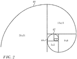
- Fibonacci numbers are the numbers in the following integer sequence, called the Fibonacci sequence, and characterized by the fact that every number after the first two is the sum of the two preceding ones: 1, 1, 2, 3, 5, 8, 13, 21, 34, 55, 89, 144.
- Fig. 2 is a diagram illustrating one well-known method of approximating a logarithmic spiral by forming a tiling with squares whose side lengths are successive Fibonacci numbers beginning at a point of origin.
- Spiral 40 formed of circular arcs passing through the corners of the squares, e.g., corners 42, 44 approaches a golden spiral as the spiral diverges outwardly from the origin, because the ratio of each element in the Fibonacci sequence to the preceding element converges on Phi, 1.618, known as the golden ratio, as the series progresses.
- the series 1, 1, 2, 3, 5, 8 and 13 produce ratios of 1, 2, 1.5, 1.67, 1.6 and 1.625, respectively.
- Fig. 3 is a schematic diagram of a layout 46 of a catheter comprising multiple splines 48 in accordance with an embodiment of the invention.
- the splines may be constructed on the surface as Fibonacci spiral forms, as described with respect to Fig. 2 , the splines 48 all converging at a central point 50 and preferably equally distributed about the circumference of the balloon.
- Electrodes 52 are disposed along the splines 48. The respective distances between electrodes 52 from along each spline increase according to the Fibonacci sequence. In this embodiment the spacing of electrodes 52 is given in table 54.
- Eight sets of coefficients of spline equation 56 are given in table 58, applicable to the eight splines shown in the layout 46.
- many approximately equilateral triangles are defined.
- electrodes at points 60, 62, 64 define such a triangle, as do electrodes at points 66, 68, 70.
- a deviation from equilaterality of 20% can be tolerated.
- Fig. 4 is a diagram illustrating a layout with two intersecting sets of Fibonacci spirals having opposite curvatures in accordance with an embodiment of the invention, one set having a left-directed curvature and the other set having a right-directed curvature.
- the terms "left-directed” and “right-directed” are used arbitrarily herein to distinguish the curvatures of the spirals.
- spirals 72, 74 are in different sets.
- Electrodes are disposed at the intersection of the sets, such as electrode 76, which is at an intersection of the spiral 72 and its neighboring spiral 74.
- electrode 78 is located at the intersection of spirals 72, 80.
- Electrodes 78, 76, 82, all on intersections of neighboring spirals define a triangle, which is approximately equilateral.
- the two sets of spirals can be constructed using the equation 56 ( Fig. 3 ) with an appropriate change in direction
- the opposing splines form a weave, which when incorporated into a balloon assembly of a catheter advantageously tends to stabilize the balloon surface.
- Such balloon assemblies can be constructed according to the teachings of commonly assigned U.S. Patent Application Publication No. 2016/0324571 , entitled Spring Loaded Balloon, which is herein incorporated by reference.
- Fig. 5 is a schematic side elevation of a catheter 84 in accordance with an embodiment of the invention.
- Catheter body 86 comprises an elongated tubular construction having a single, axial or central lumen 88, but can optionally have multiple lumens along all or part of its length if desired.
- the catheter body 86 is flexible, i.e., bendable, but substantially non-compressible along its length.
- the catheter body 86 can be of any suitable construction and made of any suitable material.
- Fig. 6 is a sectional schematic view of a portion of the catheter of Fig. 5 , taken through line 6-6 in accordance with an embodiment of the invention.
- a spine mounting assembly 90 mounted in the distal end of the lumen 88 of the catheter body 86 in accordance with an embodiment of the invention.
- One construction of the catheter body 86 comprises an outer wall 92 made of polyurethane or pebax® (polyether block amide).
- the outer wall 92 comprises an imbedded braided mesh of stainless steel or the like, as is generally known in the art, to increase torsional stiffness of the catheter body 86 so that, when a control handle 94 is rotated, the distal end of the catheter body 86 rotates in a corresponding manner.
- the length of the catheter body 86 is not critical, but preferably ranges from about 190 cm to about 120 cm, and more preferably is about 110 cm.
- the outer diameter of the catheter body 86 is also not critical, but is preferably no more than about 8 french, more preferably about 7 french.
- the thickness of the outer wall 92 is not critical, but is preferably thin enough so that the central lumen 88 can accommodate puller wires, lead wires, sensor cables and any other wires, cables or tubes. If desired, the inner surface of the outer wall 92 is lined with a stiffening tube (not shown) to provide improved torsional stability.
- a mapping assembly 96 comprises eight splines 98, which are configured as Fibonacci spirals, as described above.
- Each of the splines 98 has a proximal end attached at the distal end of the catheter body 86 and a free distal end, i.e., the distal end is not attached to any of the other splines, to the catheter body, or to any other structure that confines movement of the distal end.
- Each of the splines 98 contains a support arm 100 comprising a metal or plastic material that has shape memory, such that the support arm 100 forms an initial shape when no external forces are applied, forms a deflected shape when an external force is applied, and returns to its initial shape when the external force is released.
- the support arm 100 comprises a superelastic material, for example a nickel-titanium alloy, such as Nitinol.
- Each of the splines 98 also comprises a non-conductive covering 102 in surrounding relation to the support arm 100.
- the non-conductive covering 102 comprises a biocompatible plastic tubing, such as a polyurethane or polyimide tubing.
- a first non-conducting tube 104 is disposed between an outer mounting ring 106 and the support arm 100, and a second non-conducting tube 108 is disposed between the support arm 100 and a mounting structure 110.
- the non-conducting tubes 104, 108 which may be polyimide tubes, ensure that each support arm 100 remains electrically isolated.
- a mounting ring inner tube 112 is secured within the mounting structure 110.
- the mounting ring inner tube 112 preferably comprises a non-conducting material such as polyimide.
- the mounting ring inner tube 112 defines a mounting ring lumen 114 through which electrode lead wires 116 and sensor cables 118 extend.
- the number of splines 98 can vary as desired depending on the particular application, so that the catheter has at least two splines, preferably at least three splines, more preferably at least eight splines and as many as 12 or more splines.
- the splines 98 are moveable between an expanded arrangement, wherein, for example, each spline spirals outwardly from the catheter body 86, or the splines 98 may be arranged in a collapsed arrangement, wherein, for example, each spline is disposed generally along a longitudinal axis of the catheter body 86 so that the splines are capable of fitting within a lumen of a guiding sheath.
- Fig. 7 is a longitudinal sectional view of one of the splines 98 ( Fig. 5 ), in accordance with an embodiment of the invention.
- Each of the splines 98 carries at least one electrode mounted along its length, disposed as described above.
- a tip electrode 120 may be mounted on a distal end of each non-conductive covering 102 and at least one ring electrode 122 is mounted on each non-conductive covering 102, preferably on the distal end of the non-conductive covering 102.
- the ring electrode 122 is used as a reference electrode.
- the distance between the tip electrode and ring electrode preferably ranges from about 0.5 mm to about 2 mm.
- the tip electrode 120 is eliminated and at least two ring electrodes 122 are mounted on each non-conductive covering 102, preferably on the distal end of the non-conductive covering 102.
- Another alternative embodiment is a unipolar arrangement, in which the tip electrode 120 is mounted on the distal end of each non-conductive covering 102, with one or more reference ring electrodes mounted on the distal end of the catheter body 86, or one or more reference electrodes attached outside the body of the patient (e.g., in the form of a patch).
- a ring electrode 122 mounted on each non-conductive covering 102, preferably on the distal end of the non-conductive covering 102 is used instead of tip electrode 120.
- Each of the splines 98 may also include at least one location sensor 124.
- the location sensor 124 is mounted near the distal end of each spine. In the depicted embodiment, where each spline 98 comprises tip electrode 120.
- the location sensor 124 is mounted such that the distal end of the location sensor 124 is secured within its corresponding tip electrode 120, while the proximate end of the location sensor 124 extends into the distal end of the non-conductive covering 102.
- Each location sensor 124 is used to determine the coordinates of its corresponding tip electrode 120 at each instant when the tip electrode 120 is being used to collect an electrical mapping data point. As a result, both electrical and locational data can be obtained for each data point that is mapped.
- the location sensor 124 is mounted near the distal end of the non-conductive covering 102, preferably as close to the distal end of the spline 98 as possible or in a plane concentric with the ring electrode 122.
- Each location sensor 124 is connected to a corresponding sensor cable 118.
- Each sensor cable 118 extends through the non-conductive covering 102, catheter body 86 and control handle 94 and out the proximal end of the control handle 94.
- Each tip electrode 120 has an exposed length preferably ranging from about 0.5 mm to about 4 mm, more preferably from about 0.5 mm to about 2 mm, still more preferably about 1 mm.
- Each ring electrode 122 has a length preferably up to about 2 mm, more preferably from about 0.5 mm to about 1 mm.
- Each tip electrode 120 and each ring electrode 122 is electrically connected to an electrode lead wire 116, which in turn is electrically connected to a connector 126 ( Fig. 5 ).
- the connector 126 is connected to an appropriate mapping or monitoring system (not shown).
- Each electrode lead wire 116 extends from the connector 126, through the control handle 94, through the central lumen 88 in the catheter body 86, and into the non-conductive covering 102 of the splines 98 where it is attached to its corresponding tip electrode 120 or ring electrode 122.
- Each lead wire 116 which includes a non-conductive coating over almost all of its length, is attached to its corresponding tip electrode 120 or ring electrode 122 by any suitable method.
- FIG. 8 is a schematic diagram of a partially unfolded catheter 128 in accordance with an embodiment of the invention.
- Spiral assembly 130 may be provided with a distal locking element, such as a hook 132.
- the assembly 130 is attached to a rotator shaft 134, which is inserted through a lumen 136 of the catheter 128.
- a rotator shaft 134 As the assembly 130 extends beyond distal end 138 of the catheter 128 it eventually encounters a wall of the atrium, and is held in place against the wall by the hook 132. Deployment of the assembly 130 is then completed by retracting and concurrently turning the rotator shaft 134, causing the assembly 130 to assume an expanded spiral configuration as shown in Fig. 5 .
- Fig. 9 is a diagram illustrating the calculation of velocity vectors for an electrical wave on a triangular mesh in accordance with an embodiment of the invention.
- Triangle 140 has edges, including edges 142, 144.
- a velocity vector exists at each edge.
- the velocity vector for edge 144 is calculated in like manner.
- 3-dimensional splines formed as Fibonacci spirals are realized in a balloon catheter. Except for the spiral arrangement of the splines, a catheter of this sort can be constructed and introduced conventionally, as described, for example in commonly assigned U.S. Patent Application Publication Nos. 20160175041 entitled Balloon for Ablation around Pulmonary Veins, 20160324571 entitled Spring-Loaded Balloon, and U.S. Patent No. 9,352,134 entitled Segmented Balloon Catheter, which are all herein incorporated by reference.
- Fig. 10 is a schematic diagram of a 3-dimensional spline assembly 150, in accordance with an embodiment of the invention.
- Splines 152 configured as Fibonacci spirals as described above, but now stretched to form a 3-dimensional surface, extend from a central location 154, which may comprise a central electrode, along the surface of the assembly 150.
- the splines 152 when distorted in this manner, form a sphere or an ellipsoid with a major diameter generally aligned with the axial dimension of the assembly 150.
- the 2-dimensional spline arrangement shown in Fig. 4 may be deformed to form such a 3-dimensional structure.
- the splines 152 may be adhered to the exterior surface, the interior surface, or be embedded within the substance of a balloon.
- the splines may form a basket catheter as is known in the art. Electrodes (not shown) are distributed on the splines at distances from the central location 154 corresponding to the Fibonacci sequence.
Landscapes
- Health & Medical Sciences (AREA)
- Life Sciences & Earth Sciences (AREA)
- Engineering & Computer Science (AREA)
- Heart & Thoracic Surgery (AREA)
- Public Health (AREA)
- Veterinary Medicine (AREA)
- Biomedical Technology (AREA)
- General Health & Medical Sciences (AREA)
- Animal Behavior & Ethology (AREA)
- Biophysics (AREA)
- Surgery (AREA)
- Physics & Mathematics (AREA)
- Medical Informatics (AREA)
- Molecular Biology (AREA)
- Pathology (AREA)
- Cardiology (AREA)
- Pulmonology (AREA)
- Anesthesiology (AREA)
- Hematology (AREA)
- Physiology (AREA)
- Plasma & Fusion (AREA)
- Nuclear Medicine, Radiotherapy & Molecular Imaging (AREA)
- Otolaryngology (AREA)
- Measurement And Recording Of Electrical Phenomena And Electrical Characteristics Of The Living Body (AREA)
- Surgical Instruments (AREA)
- Media Introduction/Drainage Providing Device (AREA)
- Electrotherapy Devices (AREA)
Applications Claiming Priority (1)
| Application Number | Priority Date | Filing Date | Title |
|---|---|---|---|
| US15/651,888 US11109788B2 (en) | 2017-07-17 | 2017-07-17 | Catheter with Fibonacci distributed electrodes |
Publications (2)
| Publication Number | Publication Date |
|---|---|
| EP3430996A1 true EP3430996A1 (fr) | 2019-01-23 |
| EP3430996B1 EP3430996B1 (fr) | 2021-12-22 |
Family
ID=63103754
Family Applications (1)
| Application Number | Title | Priority Date | Filing Date |
|---|---|---|---|
| EP18183654.5A Not-in-force EP3430996B1 (fr) | 2017-07-17 | 2018-07-16 | Cathéter à électrodes réparties en fibonacci |
Country Status (7)
| Country | Link |
|---|---|
| US (1) | US11109788B2 (fr) |
| EP (1) | EP3430996B1 (fr) |
| JP (1) | JP7066558B2 (fr) |
| CN (1) | CN109259854B (fr) |
| AU (1) | AU2018204085A1 (fr) |
| CA (1) | CA3010948A1 (fr) |
| IL (1) | IL260243B2 (fr) |
Cited By (1)
| Publication number | Priority date | Publication date | Assignee | Title |
|---|---|---|---|---|
| EP4389036A1 (fr) * | 2022-12-20 | 2024-06-26 | Biosense Webster (Israel) Ltd. | Effecteur d'extrémité en panier à électrodes multiples d'un cathéter |
Families Citing this family (63)
| Publication number | Priority date | Publication date | Assignee | Title |
|---|---|---|---|---|
| WO2015192027A1 (fr) | 2014-06-12 | 2015-12-17 | Iowa Approach Inc. | Procédé et appareil d'ablation transurétrale de tissu rapide et sélective |
| EP4559428A3 (fr) | 2014-06-12 | 2025-08-20 | Boston Scientific Scimed, Inc. | Procede et appareil d'ablation tissulaire rapide et selective avec refroidissement |
| EP3206613B1 (fr) | 2014-10-14 | 2019-07-03 | Farapulse, Inc. | Appareil pour l'ablation rapide et sûre d'une veine cardiopulmonaire |
| US12144541B2 (en) | 2016-01-05 | 2024-11-19 | Boston Scientific Scimed, Inc. | Systems, apparatuses and methods for delivery of ablative energy to tissue |
| US10660702B2 (en) | 2016-01-05 | 2020-05-26 | Farapulse, Inc. | Systems, devices, and methods for focal ablation |
| US10172673B2 (en) | 2016-01-05 | 2019-01-08 | Farapulse, Inc. | Systems devices, and methods for delivery of pulsed electric field ablative energy to endocardial tissue |
| US10130423B1 (en) | 2017-07-06 | 2018-11-20 | Farapulse, Inc. | Systems, devices, and methods for focal ablation |
| US20170189097A1 (en) | 2016-01-05 | 2017-07-06 | Iowa Approach Inc. | Systems, apparatuses and methods for delivery of ablative energy to tissue |
| US10905329B2 (en) | 2016-06-09 | 2021-02-02 | Biosense Webster (Israel) Ltd. | Multi-function conducting elements for a catheter |
| US9987081B1 (en) | 2017-04-27 | 2018-06-05 | Iowa Approach, Inc. | Systems, devices, and methods for signal generation |
| US12029545B2 (en) | 2017-05-30 | 2024-07-09 | Biosense Webster (Israel) Ltd. | Catheter splines as location sensors |
| JP7586706B2 (ja) | 2017-09-12 | 2024-11-19 | ボストン サイエンティフィック サイムド,インコーポレイテッド | 心室フォーカルアブレーションのためのシステム、装置、及び方法 |
| CN111225627B (zh) | 2017-10-13 | 2023-05-19 | 圣犹达医疗用品心脏病学部门有限公司 | 具有高密度标测电极的导管 |
| CN111278497B (zh) | 2017-11-28 | 2024-01-12 | 圣犹达医疗用品心脏病学部门有限公司 | 管腔控制导管 |
| EP3731747B1 (fr) | 2018-03-13 | 2023-11-01 | St. Jude Medical, Cardiology Division, Inc. | Cathéter de cartographie à densité variable |
| EP3749195B1 (fr) | 2018-04-05 | 2023-10-18 | St. Jude Medical, Cardiology Division, Inc. | Cathéter de cartographie à électrodes haute densité |
| US20190314083A1 (en) | 2018-04-11 | 2019-10-17 | Biosense Webster (Israel) Ltd. | Flexible Multi-Arm Catheter with Diametrically Opposed Sensing Electrodes |
| CN115836908A (zh) | 2018-05-07 | 2023-03-24 | 波士顿科学医学有限公司 | 用于将消融能量递送到组织的系统、设备和方法 |
| US20190350649A1 (en) | 2018-05-21 | 2019-11-21 | St. Jude Medical, Cardiology Division, Inc. | Radio-frequency ablation and direct current electroporation catheters |
| JP7619937B2 (ja) | 2018-09-20 | 2025-01-22 | ボストン サイエンティフィック サイムド,インコーポレイテッド | 心内膜組織へのパルス電界アブレーションエネルギーの送達のためのシステム、装置、および方法 |
| US11445935B2 (en) * | 2018-11-26 | 2022-09-20 | Biosense Webster (Israel) Ltd. | Finding the origin of an arrythmia |
| US11045628B2 (en) | 2018-12-11 | 2021-06-29 | Biosense Webster (Israel) Ltd. | Balloon catheter with high articulation |
| US11207016B2 (en) | 2018-12-28 | 2021-12-28 | Biosense Webster (Israel) Ltd. | Mapping ECG signals using a multipole electrode assembly |
| US11850051B2 (en) | 2019-04-30 | 2023-12-26 | Biosense Webster (Israel) Ltd. | Mapping grid with high density electrode array |
| US11712172B2 (en) | 2019-07-18 | 2023-08-01 | Biosense Webster (Israel) Ltd. | Visual guidance for positioning a distal end of a medical probe |
| US11759150B2 (en) | 2019-08-27 | 2023-09-19 | Biosense Webster (Israel) Ltd. | Accurate basket catheter tracking |
| US11950930B2 (en) | 2019-12-12 | 2024-04-09 | Biosense Webster (Israel) Ltd. | Multi-dimensional acquisition of bipolar signals from a catheter |
| US11517218B2 (en) | 2019-12-20 | 2022-12-06 | Biosense Webster (Israel) Ltd. | Selective graphical presentation of electrophysiological parameters |
| US12232874B2 (en) | 2020-05-29 | 2025-02-25 | Biosense Webster (Israel) Ltd. | Electrode apparatus for diagnosis of arrhythmias |
| US11987017B2 (en) | 2020-06-08 | 2024-05-21 | Biosense Webster (Israel) Ltd. | Features to assist in assembly and testing of devices |
| US12310652B2 (en) | 2020-07-24 | 2025-05-27 | Boston Scientific Scimed, Inc. | Hybrid electroporation ablation catheter |
| JP7536995B2 (ja) | 2020-07-24 | 2024-08-20 | ボストン サイエンティフィック サイムド,インコーポレイテッド | 不可逆電気穿孔によるシングル・ショット心臓アブレーションのための電界印加 |
| EP4167886B1 (fr) | 2020-08-18 | 2024-05-01 | St. Jude Medical, Cardiology Division, Inc. | Cathéters à électrodes haute densité à suivi de position magnétique |
| CN116157085A (zh) | 2020-09-08 | 2023-05-23 | 波士顿科学医学有限公司 | 用于脉冲电场消融的波浪形电极及其系统、设备和方法 |
| US12048479B2 (en) | 2020-09-10 | 2024-07-30 | Biosense Webster (Israel) Ltd. | Surface mounted electrode catheter |
| US11950841B2 (en) | 2020-09-22 | 2024-04-09 | Biosense Webster (Israel) Ltd. | Basket catheter having insulated ablation electrodes and diagnostic electrodes |
| US11950840B2 (en) | 2020-09-22 | 2024-04-09 | Biosense Webster (Israel) Ltd. | Basket catheter having insulated ablation electrodes |
| US12082875B2 (en) | 2020-09-24 | 2024-09-10 | Biosense Webster (Israel) Ltd | Balloon catheter having a coil for sensing tissue temperature and position of the balloon |
| US11974803B2 (en) | 2020-10-12 | 2024-05-07 | Biosense Webster (Israel) Ltd. | Basket catheter with balloon |
| US12201786B2 (en) | 2020-12-17 | 2025-01-21 | Biosense Webster (Israel) Ltd. | Measurement of distal end dimension of catheters using magnetic fields |
| US11918383B2 (en) | 2020-12-21 | 2024-03-05 | Biosense Webster (Israel) Ltd. | Visualizing performance of catheter electrodes |
| CN116744870A (zh) | 2021-01-27 | 2023-09-12 | 波士顿科学医学有限公司 | 用于不可逆电穿孔消融的电压控制的脉冲序列 |
| WO2022192522A1 (fr) * | 2021-03-10 | 2022-09-15 | Galary, Inc. | Dispositifs servant à l'administration de champs électriques pulsés dans le traitement de tissu cardiaque |
| US12064170B2 (en) | 2021-05-13 | 2024-08-20 | Biosense Webster (Israel) Ltd. | Distal assembly for catheter with lumens running along spines |
| US12364426B2 (en) | 2021-08-12 | 2025-07-22 | Biosense Webster (Israel) Ltd. | Electro-anatomical mapping and annotation presented in electrophysiological procedures |
| US12004804B2 (en) | 2021-09-09 | 2024-06-11 | Biosense Webster (Israel) Ltd. | Basket catheter with mushroom shape distal tip |
| US12478424B2 (en) | 2021-09-10 | 2025-11-25 | Biosense Webster (Israel) Ltd. | Staggered pairs of biased ablation electrodes on basket catheter |
| CN113729923B (zh) * | 2021-09-30 | 2022-07-12 | 上海睿刀医疗科技有限公司 | 面消融电极导管及消融设备 |
| US12011280B2 (en) | 2021-10-04 | 2024-06-18 | Biosense Webster (Israel) Ltd. | Electrophysiological mapping in the presence of injury current |
| US12533489B2 (en) | 2021-10-08 | 2026-01-27 | Biosense Webster (Israel) Ltd. | Measuring tissue proximity for multi-electrode catheter |
| ES3025890T3 (en) * | 2021-12-01 | 2025-06-10 | Cathvision Aps | Method for analysing an intracardiac electrogram |
| US12419683B2 (en) | 2021-12-22 | 2025-09-23 | Biosense Webster (Israel) Ltd. | Irreversible electroporation with shorted electrodes |
| US12440263B2 (en) | 2022-01-20 | 2025-10-14 | Biosense Webster (Israel) Ltd. | Systems and methods for tripodic spines forming a spherical basket for improved tissue contact and current delivery |
| US12484961B2 (en) | 2022-01-20 | 2025-12-02 | Biosense Webster (Israel) Ltd. | Mechanical retainer systems for electrodes of a basket catheter, and methods of the same |
| US12446946B2 (en) | 2022-01-20 | 2025-10-21 | Biosense Webster (Israel) Ltd. | Systems and methods for a single spiral electrode assembly forming a spherical basket for improved tissue contact and current delivery |
| US12551658B2 (en) | 2022-03-25 | 2026-02-17 | St. Jude Medical, Cardiology Division, Inc. | Steerable introducer with slide block divider |
| US12616517B2 (en) | 2022-03-25 | 2026-05-05 | Biosense Webster (Israel) Ltd. | Expandable basket assemblies with linear spine patterns for improved tissue contact and methods for making thereof |
| US12616518B2 (en) | 2022-04-28 | 2026-05-05 | Biosense Webster (Israel) Ltd. | Barrel electrodes for a basket catheter, and methods of the same |
| US12471989B2 (en) | 2022-04-28 | 2025-11-18 | Biosense Webster (Israel) Ltd. | Strengthened expandable baskets for medical probes and medical probes containing strengthen expandable baskets |
| US12616519B2 (en) | 2022-12-15 | 2026-05-05 | Biosense Webster (Israel) Ltd. | Basket assembly with atraumatic tip electrode and methods of making thereof |
| US12533185B2 (en) | 2022-12-28 | 2026-01-27 | Biosense Webster (Israel) Ltd. | Basket end effector with distal position sensor |
| US12521035B2 (en) | 2022-12-29 | 2026-01-13 | Biosense Webster (Israel) Ltd. | Cylindrical cage systems and methods for distributed tissue contact for mapping and ablation |
| WO2024155619A1 (fr) * | 2023-01-18 | 2024-07-25 | Boston Scientific Scimed, Inc. | Cathéter à délivrance de champ asymétrique |
Citations (20)
| Publication number | Priority date | Publication date | Assignee | Title |
|---|---|---|---|---|
| WO1996005768A1 (fr) | 1994-08-19 | 1996-02-29 | Biosense, Inc. | Systemes medicaux de diagnostic, de traitement et d'imagerie |
| US5546951A (en) | 1993-07-20 | 1996-08-20 | Biosense, Inc. | Method and apparatus for studying cardiac arrhythmias |
| US5738096A (en) | 1993-07-20 | 1998-04-14 | Biosense, Inc. | Cardiac electromechanics |
| US6064905A (en) | 1998-06-18 | 2000-05-16 | Cordis Webster, Inc. | Multi-element tip electrode mapping catheter |
| US6226542B1 (en) | 1998-07-24 | 2001-05-01 | Biosense, Inc. | Three-dimensional reconstruction of intrabody organs |
| US6301496B1 (en) | 1998-07-24 | 2001-10-09 | Biosense, Inc. | Vector mapping of three-dimensionally reconstructed intrabody organs and method of display |
| EP1332724A1 (fr) * | 2002-01-31 | 2003-08-06 | Biosense, Inc. | Isolation de la veine pulmonaire a l'aide d'une radiofréquence |
| US6690963B2 (en) | 1995-01-24 | 2004-02-10 | Biosense, Inc. | System for determining the location and orientation of an invasive medical instrument |
| US6892091B1 (en) | 2000-02-18 | 2005-05-10 | Biosense, Inc. | Catheter, method and apparatus for generating an electrical map of a chamber of the heart |
| US6997924B2 (en) | 2002-09-17 | 2006-02-14 | Biosense Inc. | Laser pulmonary vein isolation |
| US20060276703A1 (en) | 2001-12-31 | 2006-12-07 | Biosense Webster, Inc. | Catheter having multiple spines each having electrical mapping and location sensing capabilities |
| US7156816B2 (en) | 2002-11-26 | 2007-01-02 | Biosense, Inc. | Ultrasound pulmonary vein isolation |
| US7536218B2 (en) | 2005-07-15 | 2009-05-19 | Biosense Webster, Inc. | Hybrid magnetic-based and impedance-based position sensing |
| US7756576B2 (en) | 2005-08-26 | 2010-07-13 | Biosense Webster, Inc. | Position sensing and detection of skin impedance |
| US8478383B2 (en) | 2010-12-14 | 2013-07-02 | Biosense Webster (Israel), Ltd. | Probe tracking using multiple tracking methods |
| US20140257069A1 (en) * | 2013-03-08 | 2014-09-11 | St. Jude Medical, Atrial Fibrillation Division, Inc. | Basket for a multi-electrode array catheter |
| US20150208937A1 (en) * | 2014-01-28 | 2015-07-30 | John Bullinga | Catheter system for mapping of the left atrium, right atrium and coronary sinus |
| US9352134B2 (en) | 2013-11-01 | 2016-05-31 | Biosense Webster (Israel) Ltd. | Segmented balloon catheter |
| US20160175041A1 (en) | 2014-12-22 | 2016-06-23 | Biosense Webster (Israel) Ltd. | Balloon for ablation around pulmonary veins |
| US20160324571A1 (en) | 2015-05-07 | 2016-11-10 | Biosense Webster (Israel) Ltd. | Spring-Loaded Balloon |
Family Cites Families (16)
| Publication number | Priority date | Publication date | Assignee | Title |
|---|---|---|---|---|
| US5443470A (en) | 1992-05-01 | 1995-08-22 | Vesta Medical, Inc. | Method and apparatus for endometrial ablation |
| US6281681B1 (en) | 1999-01-28 | 2001-08-28 | General Electric Company | Magnetic resonance imaging with interleaved Fibonacci spiral scanning |
| US6405067B1 (en) * | 2000-07-07 | 2002-06-11 | Biosense Webster, Inc. | Catheter with tip electrode having a recessed ring electrode mounted thereon |
| US7179256B2 (en) * | 2003-10-24 | 2007-02-20 | Biosense Webster, Inc. | Catheter with ablation needle and mapping assembly |
| US7729752B2 (en) | 2006-06-13 | 2010-06-01 | Rhythmia Medical, Inc. | Non-contact cardiac mapping, including resolution map |
| GB0902339D0 (en) * | 2009-02-12 | 2009-04-01 | St Georges Healthcare Nhs Trus | Percutaneous guidewire |
| WO2012058289A2 (fr) | 2010-10-27 | 2012-05-03 | Dignity Health | Système de stimulation électrique utérine et méthode associée |
| US10517667B2 (en) | 2014-05-16 | 2019-12-31 | Biosense Webster (Israel) Ltd. | Catheter tip with microelectrodes |
| US20130345583A1 (en) * | 2012-06-20 | 2013-12-26 | Boston Scientific Scimed, Inc. | Suppression of global activity during multi-channel electrophysiology mapping using a whitening filter |
| EP2710953B1 (fr) | 2012-09-21 | 2015-03-04 | BIOTRONIK SE & Co. KG | Procédé d'augmentation du rapport signal/bruit (SNR) de signaux de mesure d'électrocardiogramme (ECG) et dispositif cardiaque destiné à être utilisé dans la détection de battements de coeur |
| US10537286B2 (en) | 2013-01-08 | 2020-01-21 | Biosense Webster (Israel) Ltd. | Catheter with multiple spines of different lengths arranged in one or more distal assemblies |
| US9655715B2 (en) * | 2013-07-11 | 2017-05-23 | Tepha, Inc. | Absorbable implants for plastic surgery |
| US10130799B2 (en) * | 2014-08-27 | 2018-11-20 | Acclarent, Inc. | Inflator with varying mechanical advantage |
| US9833161B2 (en) * | 2015-02-09 | 2017-12-05 | Biosense Webster (Israel) Ltd. | Basket catheter with far-field electrode |
| JP2017047180A (ja) | 2015-09-04 | 2017-03-09 | キヤノン株式会社 | 探触子アレイ、および、該探触子アレイを備えた音響波測定装置。 |
| US11344259B2 (en) * | 2017-01-11 | 2022-05-31 | Abbott Cardiovascular Systems Inc. | Expandable member for an electrophysiology catheter |
-
2017
- 2017-07-17 US US15/651,888 patent/US11109788B2/en not_active Expired - Fee Related
-
2018
- 2018-06-08 AU AU2018204085A patent/AU2018204085A1/en not_active Abandoned
- 2018-06-24 IL IL260243A patent/IL260243B2/en unknown
- 2018-07-10 CA CA3010948A patent/CA3010948A1/fr not_active Abandoned
- 2018-07-13 JP JP2018132968A patent/JP7066558B2/ja not_active Expired - Fee Related
- 2018-07-16 CN CN201810776945.0A patent/CN109259854B/zh active Active
- 2018-07-16 EP EP18183654.5A patent/EP3430996B1/fr not_active Not-in-force
Patent Citations (21)
| Publication number | Priority date | Publication date | Assignee | Title |
|---|---|---|---|---|
| US5546951A (en) | 1993-07-20 | 1996-08-20 | Biosense, Inc. | Method and apparatus for studying cardiac arrhythmias |
| US5738096A (en) | 1993-07-20 | 1998-04-14 | Biosense, Inc. | Cardiac electromechanics |
| WO1996005768A1 (fr) | 1994-08-19 | 1996-02-29 | Biosense, Inc. | Systemes medicaux de diagnostic, de traitement et d'imagerie |
| US6690963B2 (en) | 1995-01-24 | 2004-02-10 | Biosense, Inc. | System for determining the location and orientation of an invasive medical instrument |
| US6064905A (en) | 1998-06-18 | 2000-05-16 | Cordis Webster, Inc. | Multi-element tip electrode mapping catheter |
| US6226542B1 (en) | 1998-07-24 | 2001-05-01 | Biosense, Inc. | Three-dimensional reconstruction of intrabody organs |
| US6301496B1 (en) | 1998-07-24 | 2001-10-09 | Biosense, Inc. | Vector mapping of three-dimensionally reconstructed intrabody organs and method of display |
| US6892091B1 (en) | 2000-02-18 | 2005-05-10 | Biosense, Inc. | Catheter, method and apparatus for generating an electrical map of a chamber of the heart |
| US20060276703A1 (en) | 2001-12-31 | 2006-12-07 | Biosense Webster, Inc. | Catheter having multiple spines each having electrical mapping and location sensing capabilities |
| EP1332724A1 (fr) * | 2002-01-31 | 2003-08-06 | Biosense, Inc. | Isolation de la veine pulmonaire a l'aide d'une radiofréquence |
| US6814733B2 (en) | 2002-01-31 | 2004-11-09 | Biosense, Inc. | Radio frequency pulmonary vein isolation |
| US6997924B2 (en) | 2002-09-17 | 2006-02-14 | Biosense Inc. | Laser pulmonary vein isolation |
| US7156816B2 (en) | 2002-11-26 | 2007-01-02 | Biosense, Inc. | Ultrasound pulmonary vein isolation |
| US7536218B2 (en) | 2005-07-15 | 2009-05-19 | Biosense Webster, Inc. | Hybrid magnetic-based and impedance-based position sensing |
| US7756576B2 (en) | 2005-08-26 | 2010-07-13 | Biosense Webster, Inc. | Position sensing and detection of skin impedance |
| US8478383B2 (en) | 2010-12-14 | 2013-07-02 | Biosense Webster (Israel), Ltd. | Probe tracking using multiple tracking methods |
| US20140257069A1 (en) * | 2013-03-08 | 2014-09-11 | St. Jude Medical, Atrial Fibrillation Division, Inc. | Basket for a multi-electrode array catheter |
| US9352134B2 (en) | 2013-11-01 | 2016-05-31 | Biosense Webster (Israel) Ltd. | Segmented balloon catheter |
| US20150208937A1 (en) * | 2014-01-28 | 2015-07-30 | John Bullinga | Catheter system for mapping of the left atrium, right atrium and coronary sinus |
| US20160175041A1 (en) | 2014-12-22 | 2016-06-23 | Biosense Webster (Israel) Ltd. | Balloon for ablation around pulmonary veins |
| US20160324571A1 (en) | 2015-05-07 | 2016-11-10 | Biosense Webster (Israel) Ltd. | Spring-Loaded Balloon |
Cited By (1)
| Publication number | Priority date | Publication date | Assignee | Title |
|---|---|---|---|---|
| EP4389036A1 (fr) * | 2022-12-20 | 2024-06-26 | Biosense Webster (Israel) Ltd. | Effecteur d'extrémité en panier à électrodes multiples d'un cathéter |
Also Published As
| Publication number | Publication date |
|---|---|
| US20190015007A1 (en) | 2019-01-17 |
| IL260243B2 (en) | 2023-07-01 |
| IL260243B1 (en) | 2023-03-01 |
| JP2019018011A (ja) | 2019-02-07 |
| CN109259854B (zh) | 2023-10-03 |
| JP7066558B2 (ja) | 2022-05-13 |
| CN109259854A (zh) | 2019-01-25 |
| CA3010948A1 (fr) | 2019-01-17 |
| EP3430996B1 (fr) | 2021-12-22 |
| US11109788B2 (en) | 2021-09-07 |
| IL260243A (en) | 2019-01-31 |
| AU2018204085A1 (en) | 2019-01-31 |
Similar Documents
| Publication | Publication Date | Title |
|---|---|---|
| EP3430996B1 (fr) | Cathéter à électrodes réparties en fibonacci | |
| US10045707B2 (en) | Basket catheter with far-field electrode | |
| EP3937813B1 (fr) | Panier d'électrodes ayant une bande circonférentielle à haute densité d'électrodes | |
| US10682181B2 (en) | Methods and systems for modeling and registration of 3-dimensional images of the heart | |
| JP4027976B2 (ja) | マッピング用カテーテル | |
| EP2151209B1 (fr) | Capteurs à axe unique sur une ossature flexible | |
| KR100789117B1 (ko) | 심실의 전기적 맵을 생성하기 위한 카테터, 방법 및 장치 | |
| US11350991B2 (en) | All-in-one spiral catheter | |
| EP2229904A1 (fr) | Cathéter lasso double fonction doté d'irrigation | |
| CA3017171A1 (fr) | Afficheur automatique du plus recent point lat | |
| US20230028867A1 (en) | Accurate tissue proximity | |
| CN118252606A (zh) | 用于经由三角测量来标测组织接触的系统和方法 | |
| EP4393389B1 (fr) | Systèmes de mappage de contact tissulaire par triangulation |
Legal Events
| Date | Code | Title | Description |
|---|---|---|---|
| PUAI | Public reference made under article 153(3) epc to a published international application that has entered the european phase |
Free format text: ORIGINAL CODE: 0009012 |
|
| STAA | Information on the status of an ep patent application or granted ep patent |
Free format text: STATUS: THE APPLICATION HAS BEEN PUBLISHED |
|
| AK | Designated contracting states |
Kind code of ref document: A1 Designated state(s): AL AT BE BG CH CY CZ DE DK EE ES FI FR GB GR HR HU IE IS IT LI LT LU LV MC MK MT NL NO PL PT RO RS SE SI SK SM TR |
|
| AX | Request for extension of the european patent |
Extension state: BA ME |
|
| STAA | Information on the status of an ep patent application or granted ep patent |
Free format text: STATUS: REQUEST FOR EXAMINATION WAS MADE |
|
| 17P | Request for examination filed |
Effective date: 20190716 |
|
| RBV | Designated contracting states (corrected) |
Designated state(s): AL AT BE BG CH CY CZ DE DK EE ES FI FR GB GR HR HU IE IS IT LI LT LU LV MC MK MT NL NO PL PT RO RS SE SI SK SM TR |
|
| REG | Reference to a national code |
Ref country code: DE Ref legal event code: R079 Ref document number: 602018028426 Country of ref document: DE Free format text: PREVIOUS MAIN CLASS: A61B0005042000 Ipc: A61B0005287000 |
|
| GRAP | Despatch of communication of intention to grant a patent |
Free format text: ORIGINAL CODE: EPIDOSNIGR1 |
|
| STAA | Information on the status of an ep patent application or granted ep patent |
Free format text: STATUS: GRANT OF PATENT IS INTENDED |
|
| RIC1 | Information provided on ipc code assigned before grant |
Ipc: A61B 5/287 20210101AFI20210111BHEP |
|
| INTG | Intention to grant announced |
Effective date: 20210204 |
|
| GRAJ | Information related to disapproval of communication of intention to grant by the applicant or resumption of examination proceedings by the epo deleted |
Free format text: ORIGINAL CODE: EPIDOSDIGR1 |
|
| STAA | Information on the status of an ep patent application or granted ep patent |
Free format text: STATUS: REQUEST FOR EXAMINATION WAS MADE |
|
| GRAP | Despatch of communication of intention to grant a patent |
Free format text: ORIGINAL CODE: EPIDOSNIGR1 |
|
| INTC | Intention to grant announced (deleted) | ||
| STAA | Information on the status of an ep patent application or granted ep patent |
Free format text: STATUS: GRANT OF PATENT IS INTENDED |
|
| INTG | Intention to grant announced |
Effective date: 20210708 |
|
| GRAS | Grant fee paid |
Free format text: ORIGINAL CODE: EPIDOSNIGR3 |
|
| GRAA | (expected) grant |
Free format text: ORIGINAL CODE: 0009210 |
|
| STAA | Information on the status of an ep patent application or granted ep patent |
Free format text: STATUS: THE PATENT HAS BEEN GRANTED |
|
| AK | Designated contracting states |
Kind code of ref document: B1 Designated state(s): AL AT BE BG CH CY CZ DE DK EE ES FI FR GB GR HR HU IE IS IT LI LT LU LV MC MK MT NL NO PL PT RO RS SE SI SK SM TR |
|
| REG | Reference to a national code |
Ref country code: GB Ref legal event code: FG4D |
|
| REG | Reference to a national code |
Ref country code: CH Ref legal event code: EP |
|
| REG | Reference to a national code |
Ref country code: DE Ref legal event code: R096 Ref document number: 602018028426 Country of ref document: DE |
|
| REG | Reference to a national code |
Ref country code: AT Ref legal event code: REF Ref document number: 1456555 Country of ref document: AT Kind code of ref document: T Effective date: 20220115 |
|
| REG | Reference to a national code |
Ref country code: IE Ref legal event code: FG4D |
|
| REG | Reference to a national code |
Ref country code: NL Ref legal event code: FP |
|
| REG | Reference to a national code |
Ref country code: LT Ref legal event code: MG9D |
|
| PG25 | Lapsed in a contracting state [announced via postgrant information from national office to epo] |
Ref country code: RS Free format text: LAPSE BECAUSE OF FAILURE TO SUBMIT A TRANSLATION OF THE DESCRIPTION OR TO PAY THE FEE WITHIN THE PRESCRIBED TIME-LIMIT Effective date: 20211222 Ref country code: LT Free format text: LAPSE BECAUSE OF FAILURE TO SUBMIT A TRANSLATION OF THE DESCRIPTION OR TO PAY THE FEE WITHIN THE PRESCRIBED TIME-LIMIT Effective date: 20211222 Ref country code: FI Free format text: LAPSE BECAUSE OF FAILURE TO SUBMIT A TRANSLATION OF THE DESCRIPTION OR TO PAY THE FEE WITHIN THE PRESCRIBED TIME-LIMIT Effective date: 20211222 Ref country code: BG Free format text: LAPSE BECAUSE OF FAILURE TO SUBMIT A TRANSLATION OF THE DESCRIPTION OR TO PAY THE FEE WITHIN THE PRESCRIBED TIME-LIMIT Effective date: 20220322 |
|
| REG | Reference to a national code |
Ref country code: AT Ref legal event code: MK05 Ref document number: 1456555 Country of ref document: AT Kind code of ref document: T Effective date: 20211222 |
|
| PG25 | Lapsed in a contracting state [announced via postgrant information from national office to epo] |
Ref country code: SE Free format text: LAPSE BECAUSE OF FAILURE TO SUBMIT A TRANSLATION OF THE DESCRIPTION OR TO PAY THE FEE WITHIN THE PRESCRIBED TIME-LIMIT Effective date: 20211222 Ref country code: NO Free format text: LAPSE BECAUSE OF FAILURE TO SUBMIT A TRANSLATION OF THE DESCRIPTION OR TO PAY THE FEE WITHIN THE PRESCRIBED TIME-LIMIT Effective date: 20220322 Ref country code: LV Free format text: LAPSE BECAUSE OF FAILURE TO SUBMIT A TRANSLATION OF THE DESCRIPTION OR TO PAY THE FEE WITHIN THE PRESCRIBED TIME-LIMIT Effective date: 20211222 Ref country code: HR Free format text: LAPSE BECAUSE OF FAILURE TO SUBMIT A TRANSLATION OF THE DESCRIPTION OR TO PAY THE FEE WITHIN THE PRESCRIBED TIME-LIMIT Effective date: 20211222 Ref country code: GR Free format text: LAPSE BECAUSE OF FAILURE TO SUBMIT A TRANSLATION OF THE DESCRIPTION OR TO PAY THE FEE WITHIN THE PRESCRIBED TIME-LIMIT Effective date: 20220323 |
|
| PG25 | Lapsed in a contracting state [announced via postgrant information from national office to epo] |
Ref country code: SM Free format text: LAPSE BECAUSE OF FAILURE TO SUBMIT A TRANSLATION OF THE DESCRIPTION OR TO PAY THE FEE WITHIN THE PRESCRIBED TIME-LIMIT Effective date: 20211222 Ref country code: SK Free format text: LAPSE BECAUSE OF FAILURE TO SUBMIT A TRANSLATION OF THE DESCRIPTION OR TO PAY THE FEE WITHIN THE PRESCRIBED TIME-LIMIT Effective date: 20211222 Ref country code: RO Free format text: LAPSE BECAUSE OF FAILURE TO SUBMIT A TRANSLATION OF THE DESCRIPTION OR TO PAY THE FEE WITHIN THE PRESCRIBED TIME-LIMIT Effective date: 20211222 Ref country code: PT Free format text: LAPSE BECAUSE OF FAILURE TO SUBMIT A TRANSLATION OF THE DESCRIPTION OR TO PAY THE FEE WITHIN THE PRESCRIBED TIME-LIMIT Effective date: 20220422 Ref country code: ES Free format text: LAPSE BECAUSE OF FAILURE TO SUBMIT A TRANSLATION OF THE DESCRIPTION OR TO PAY THE FEE WITHIN THE PRESCRIBED TIME-LIMIT Effective date: 20211222 Ref country code: EE Free format text: LAPSE BECAUSE OF FAILURE TO SUBMIT A TRANSLATION OF THE DESCRIPTION OR TO PAY THE FEE WITHIN THE PRESCRIBED TIME-LIMIT Effective date: 20211222 Ref country code: CZ Free format text: LAPSE BECAUSE OF FAILURE TO SUBMIT A TRANSLATION OF THE DESCRIPTION OR TO PAY THE FEE WITHIN THE PRESCRIBED TIME-LIMIT Effective date: 20211222 |
|
| PGFP | Annual fee paid to national office [announced via postgrant information from national office to epo] |
Ref country code: NL Payment date: 20220615 Year of fee payment: 5 Ref country code: IT Payment date: 20220613 Year of fee payment: 5 Ref country code: GB Payment date: 20220606 Year of fee payment: 5 |
|
| PG25 | Lapsed in a contracting state [announced via postgrant information from national office to epo] |
Ref country code: AT Free format text: LAPSE BECAUSE OF FAILURE TO SUBMIT A TRANSLATION OF THE DESCRIPTION OR TO PAY THE FEE WITHIN THE PRESCRIBED TIME-LIMIT Effective date: 20211222 Ref country code: PL Free format text: LAPSE BECAUSE OF FAILURE TO SUBMIT A TRANSLATION OF THE DESCRIPTION OR TO PAY THE FEE WITHIN THE PRESCRIBED TIME-LIMIT Effective date: 20211222 |
|
| REG | Reference to a national code |
Ref country code: DE Ref legal event code: R097 Ref document number: 602018028426 Country of ref document: DE |
|
| PG25 | Lapsed in a contracting state [announced via postgrant information from national office to epo] |
Ref country code: IS Free format text: LAPSE BECAUSE OF FAILURE TO SUBMIT A TRANSLATION OF THE DESCRIPTION OR TO PAY THE FEE WITHIN THE PRESCRIBED TIME-LIMIT Effective date: 20220422 |
|
| PGFP | Annual fee paid to national office [announced via postgrant information from national office to epo] |
Ref country code: FR Payment date: 20220609 Year of fee payment: 5 |
|
| PLBE | No opposition filed within time limit |
Free format text: ORIGINAL CODE: 0009261 |
|
| STAA | Information on the status of an ep patent application or granted ep patent |
Free format text: STATUS: NO OPPOSITION FILED WITHIN TIME LIMIT |
|
| PG25 | Lapsed in a contracting state [announced via postgrant information from national office to epo] |
Ref country code: DK Free format text: LAPSE BECAUSE OF FAILURE TO SUBMIT A TRANSLATION OF THE DESCRIPTION OR TO PAY THE FEE WITHIN THE PRESCRIBED TIME-LIMIT Effective date: 20211222 Ref country code: AL Free format text: LAPSE BECAUSE OF FAILURE TO SUBMIT A TRANSLATION OF THE DESCRIPTION OR TO PAY THE FEE WITHIN THE PRESCRIBED TIME-LIMIT Effective date: 20211222 |
|
| PGFP | Annual fee paid to national office [announced via postgrant information from national office to epo] |
Ref country code: DE Payment date: 20220531 Year of fee payment: 5 |
|
| 26N | No opposition filed |
Effective date: 20220923 |
|
| PG25 | Lapsed in a contracting state [announced via postgrant information from national office to epo] |
Ref country code: SI Free format text: LAPSE BECAUSE OF FAILURE TO SUBMIT A TRANSLATION OF THE DESCRIPTION OR TO PAY THE FEE WITHIN THE PRESCRIBED TIME-LIMIT Effective date: 20211222 Ref country code: MC Free format text: LAPSE BECAUSE OF FAILURE TO SUBMIT A TRANSLATION OF THE DESCRIPTION OR TO PAY THE FEE WITHIN THE PRESCRIBED TIME-LIMIT Effective date: 20211222 |
|
| REG | Reference to a national code |
Ref country code: CH Ref legal event code: PL |
|
| REG | Reference to a national code |
Ref country code: BE Ref legal event code: MM Effective date: 20220731 |
|
| PG25 | Lapsed in a contracting state [announced via postgrant information from national office to epo] |
Ref country code: LU Free format text: LAPSE BECAUSE OF NON-PAYMENT OF DUE FEES Effective date: 20220716 Ref country code: LI Free format text: LAPSE BECAUSE OF NON-PAYMENT OF DUE FEES Effective date: 20220731 Ref country code: CH Free format text: LAPSE BECAUSE OF NON-PAYMENT OF DUE FEES Effective date: 20220731 |
|
| PG25 | Lapsed in a contracting state [announced via postgrant information from national office to epo] |
Ref country code: BE Free format text: LAPSE BECAUSE OF NON-PAYMENT OF DUE FEES Effective date: 20220731 |
|
| PG25 | Lapsed in a contracting state [announced via postgrant information from national office to epo] |
Ref country code: IE Free format text: LAPSE BECAUSE OF NON-PAYMENT OF DUE FEES Effective date: 20220716 |
|
| REG | Reference to a national code |
Ref country code: DE Ref legal event code: R119 Ref document number: 602018028426 Country of ref document: DE |
|
| REG | Reference to a national code |
Ref country code: NL Ref legal event code: MM Effective date: 20230801 |
|
| GBPC | Gb: european patent ceased through non-payment of renewal fee |
Effective date: 20230716 |
|
| PG25 | Lapsed in a contracting state [announced via postgrant information from national office to epo] |
Ref country code: HU Free format text: LAPSE BECAUSE OF FAILURE TO SUBMIT A TRANSLATION OF THE DESCRIPTION OR TO PAY THE FEE WITHIN THE PRESCRIBED TIME-LIMIT; INVALID AB INITIO Effective date: 20180716 |
|
| PG25 | Lapsed in a contracting state [announced via postgrant information from national office to epo] |
Ref country code: NL Free format text: LAPSE BECAUSE OF NON-PAYMENT OF DUE FEES Effective date: 20230801 |
|
| PG25 | Lapsed in a contracting state [announced via postgrant information from national office to epo] |
Ref country code: NL Free format text: LAPSE BECAUSE OF NON-PAYMENT OF DUE FEES Effective date: 20230801 Ref country code: MK Free format text: LAPSE BECAUSE OF FAILURE TO SUBMIT A TRANSLATION OF THE DESCRIPTION OR TO PAY THE FEE WITHIN THE PRESCRIBED TIME-LIMIT Effective date: 20211222 Ref country code: DE Free format text: LAPSE BECAUSE OF NON-PAYMENT OF DUE FEES Effective date: 20240201 Ref country code: CY Free format text: LAPSE BECAUSE OF FAILURE TO SUBMIT A TRANSLATION OF THE DESCRIPTION OR TO PAY THE FEE WITHIN THE PRESCRIBED TIME-LIMIT Effective date: 20211222 Ref country code: GB Free format text: LAPSE BECAUSE OF NON-PAYMENT OF DUE FEES Effective date: 20230716 |
|
| PG25 | Lapsed in a contracting state [announced via postgrant information from national office to epo] |
Ref country code: FR Free format text: LAPSE BECAUSE OF NON-PAYMENT OF DUE FEES Effective date: 20230731 |
|
| PG25 | Lapsed in a contracting state [announced via postgrant information from national office to epo] |
Ref country code: TR Free format text: LAPSE BECAUSE OF FAILURE TO SUBMIT A TRANSLATION OF THE DESCRIPTION OR TO PAY THE FEE WITHIN THE PRESCRIBED TIME-LIMIT Effective date: 20211222 |
|
| PG25 | Lapsed in a contracting state [announced via postgrant information from national office to epo] |
Ref country code: IT Free format text: LAPSE BECAUSE OF NON-PAYMENT OF DUE FEES Effective date: 20230716 |
|
| PG25 | Lapsed in a contracting state [announced via postgrant information from national office to epo] |
Ref country code: MT Free format text: LAPSE BECAUSE OF FAILURE TO SUBMIT A TRANSLATION OF THE DESCRIPTION OR TO PAY THE FEE WITHIN THE PRESCRIBED TIME-LIMIT Effective date: 20211222 |