EP3431391B1 - Betriebssystem für aerodynamische steuerflächen für ein flugzeug unter verwendung eines variablen getriebes - Google Patents
Betriebssystem für aerodynamische steuerflächen für ein flugzeug unter verwendung eines variablen getriebes Download PDFInfo
- Publication number
- EP3431391B1 EP3431391B1 EP18184399.6A EP18184399A EP3431391B1 EP 3431391 B1 EP3431391 B1 EP 3431391B1 EP 18184399 A EP18184399 A EP 18184399A EP 3431391 B1 EP3431391 B1 EP 3431391B1
- Authority
- EP
- European Patent Office
- Prior art keywords
- control surface
- aircraft
- variable transmission
- continuously variable
- control
- Prior art date
- Legal status (The legal status is an assumption and is not a legal conclusion. Google has not performed a legal analysis and makes no representation as to the accuracy of the status listed.)
- Active
Links
Images

Classifications
-
- B—PERFORMING OPERATIONS; TRANSPORTING
- B64—AIRCRAFT; AVIATION; COSMONAUTICS
- B64C—AEROPLANES; HELICOPTERS
- B64C13/00—Control systems or transmitting systems for actuating flying-control surfaces, lift-increasing flaps, air brakes, or spoilers
- B64C13/24—Transmitting means
- B64C13/26—Transmitting means without power amplification or where power amplification is irrelevant
- B64C13/28—Transmitting means without power amplification or where power amplification is irrelevant mechanical
- B64C13/34—Transmitting means without power amplification or where power amplification is irrelevant mechanical using toothed gearing
-
- B—PERFORMING OPERATIONS; TRANSPORTING
- B64—AIRCRAFT; AVIATION; COSMONAUTICS
- B64C—AEROPLANES; HELICOPTERS
- B64C13/00—Control systems or transmitting systems for actuating flying-control surfaces, lift-increasing flaps, air brakes, or spoilers
- B64C13/24—Transmitting means
- B64C13/26—Transmitting means without power amplification or where power amplification is irrelevant
- B64C13/28—Transmitting means without power amplification or where power amplification is irrelevant mechanical
-
- B—PERFORMING OPERATIONS; TRANSPORTING
- B64—AIRCRAFT; AVIATION; COSMONAUTICS
- B64C—AEROPLANES; HELICOPTERS
- B64C13/00—Control systems or transmitting systems for actuating flying-control surfaces, lift-increasing flaps, air brakes, or spoilers
- B64C13/02—Initiating means
- B64C13/16—Initiating means actuated automatically, e.g. responsive to gust detectors
-
- B—PERFORMING OPERATIONS; TRANSPORTING
- B64—AIRCRAFT; AVIATION; COSMONAUTICS
- B64C—AEROPLANES; HELICOPTERS
- B64C9/00—Adjustable control surfaces or members, e.g. rudders
- B64C9/14—Adjustable control surfaces or members, e.g. rudders forming slots
- B64C9/16—Adjustable control surfaces or members, e.g. rudders forming slots at the rear of the wing
- B64C9/18—Adjustable control surfaces or members, e.g. rudders forming slots at the rear of the wing by single flaps
Definitions
- Modem aircraft often use a variety of high lift leading and trailing edge devices to improve high angle of attack performance during various phases of flight, for example, takeoff and landing.
- One such device is a trailing edge flap.
- Current trailing edge flaps generally have a stowed position in which the flap forms a portion of a trailing edge of a wing, and one or more deployed positions in which the flap extends forward and down to increase the camber and/or plan form area of the wing.
- the stowed position is generally associated with low drag at low angles of attack and can be suitable for cruise and other low angle of attack operations.
- the extended position(s) is/are generally associated with improved air flow characteristics over the aircraft's wing at higher angles of attack.
- each flap typically includes two actuators, one for each side of the flap. If the two actuators do not extend two sides of the flap the same amount, the flap experiences skew. Further, applying an optimum operational speed (e.g., rotational speed) can be desirable to achieve efficient extension and/or retraction of the flaps.
- EP 2902314 A1 relates to a high lift system for an aircraft.
- GB 899128A relates to a torque transmitting device.
- GB 2069426 A relates to an aircraft control mechanism.
- Control surface operating systems for controlling aerodynamic control surfaces of aircraft are provided and defined in claim 1.
- the systems include a drive system operably connected to a drive shaft, the drive system including a continuously variable transmission, at least one actuator operably connected to the drive shaft and arranged to convert rotational movement of the drive shaft to move at least a portion of the aerodynamic control surface; and at least one control surface operably connected to the at least one actuator, wherein the at least one control surface is adjusted by the at least one actuator.
- control surface operating systems may include that the at least one control surface is operably connected to two actuators.
- control surface operating systems may include that the drive system includes a power distribution unit arranged to drive the continuously variable transmission.
- control surface operating systems may include a controller arranged to control operation of the continuously variable transmission.
- control surface operating systems may include that the controller is part of the drive system.
- control surface operating systems may include that the controller controls operation of the continuously variable transmission based on a flight condition of the aircraft.
- control surface operating systems may include that the at least one control surface is one of a flap or slat on a wing or tail of the aircraft.
- the continuously variable transmission includes at least two conical gear sets to enable variable gear ratios of the continuously variable transmission.
- control surface operating systems may include that a belt is driven by the at least two conical gear sets.
- control surface operating systems may include that the drive shaft comprises at least one torque tube.
- control surface operating systems may include that the drive shaft comprises multiple torque tubes that operably connect a plurality of actuators, wherein the plurality of actuators are arranged to control operation of at least two control surfaces.
- control surface operating systems may include that the at least one actuator is a linear actuator.
- control surface operating systems may include that the at least one actuator is a rotary actuator.
- an aircraft is provided and defined in claim 10.
- the aircraft includes at least one aerodynamic control surface and a control surface operating system for controlling aerodynamic control surfaces of the aircraft.
- the control surface operating system includes a drive system operably connected to a drive shaft, the drive system including a continuously variable transmission and at least one actuator operably connected to the drive shaft and the at least one aerodynamic control surface, the at least one actuator arranged to convert rotational movement of the drive shaft to move at least a portion of the at least one aerodynamic control surface, such that the at least one control surface is adjusted by the at least one actuator.
- the continuously variable transmission includes at least two conical gear sets to enable variable gear ratios of the continuously variable transmission.
- further embodiments of the aircraft may include that the drive system includes a power distribution unit arranged to drive the continuously variable transmission.
- control surface operating system further comprises a controller arranged to control operation of the continuously variable transmission.
- further embodiments of the aircraft may include that the controller controls operation of the continuously variable transmission based on a flight condition of the aircraft.
- further embodiments of the aircraft may include that the at least one control surface is one of a flap or slat on a wing or tail of the aircraft.
- further embodiments of the aircraft may include that the drive shaft comprises multiple torque tubes that operably connect a plurality of actuators, wherein the plurality of actuators are arranged to control operation of at least two control surfaces of the aircraft.
- further embodiments of the aircraft may include that the at least one actuator is a linear actuator or a rotary actuator.
- a method of controlling operation of aerodynamic control surfaces of aircraft are provided and defined in claim 14.
- the method includes driving a drive shaft with a continuously variable transmission, the drive shaft operably coupled to at least one actuator and converting rotational movement of the drive shaft using the at least one actuator to move at least a portion of the aerodynamic control surface to adjust the aerodynamic control surface.
- the continuously variable transmission includes at least two conical gear sets to enable variable gear ratios of the continuously variable transmission.
- further embodiments of the methods may include comprising controlling operation of the continuously variable transmission based on a flight condition of the aircraft.
- Aerodynamic control surface transmission systems that provide drive and operation for aircraft flaps, slats, or other movable aerodynamic control surfaces.
- the disclosed systems provide solutions for driving movable aerodynamic control surfaces on aircraft.
- power distribution units, angle gear boxes, and actuators use fixed ratio gearing to move the movable aerodynamic control surfaces over a full load profile which includes both aiding and opposing static and aerodynamic loads.
- the fixed gearing drives a larger system power/torque capacity than is necessary, and thus inefficiencies within the system may exist. Examples of inefficiencies in such systems may include chatter, use of complex control algorithms, increased power consumption, etc.
- embodiments provided herein are directed to aerodynamic control surface transmission systems that include continuously variable transmissions that allow for control at efficient and desirable operating parameters.
- the systems descried herein include a continuously variable transmission (“CVT") operably connected to one or more movable aerodynamic control surfaces (e.g., flaps, slats, etc.) on an aircraft.
- CVT continuously variable transmission
- the CVT allows for constant motor operation with variable drive-line speed, thus enabling a smaller range of operation, and thus improved efficiencies.
- the CVT enables deployment and retraction of movable aerodynamic control surfaces at different speeds, and because of the CVT deployment and retraction can be independently optimized to an operational speed for such action. That is, embodiments provided herein, enable improved operational speeds for the different operations associated with movable aerodynamic control surfaces.
- FIG. 1 illustrates an example of an aircraft 100, illustrated as a commercial aircraft, having aircraft engines 102.
- the aircraft 100 can embody aspects of the teachings of this disclosure.
- the aircraft 100 includes two wings 104 with wing lift systems that each includes one or more aerodynamic control surfaces.
- the aerodynamic control surfaces include slats 106 and one or more flaps 108 located on the wings 104.
- the slats 106 are located on a leading edge of the wings 104 and the flaps 108 are located on a trailing edge of the wings 104.
- the aerodynamic control surfaces include slats and/or flaps 110 located on a tail 112 of the aircraft 100.
- control surface can refer to slats, flaps, and/or other controllable surfaces that are operated to enable flight control of the aircraft 100.
- description herein will be discussed with respect to the control surfaces 106, 108 located on the wings 104, those of skill in the art will appreciate that embodiments of the present disclosure can be applied to operation of the control surfaces 110 located on the tail 112 of the aircraft 100.
- the control surfaces 106, 108, 110 can be driven by one or more actuators that are operably connected to the respective control surfaces 106, 108, 110.
- Wing lift systems on aircraft typically interconnect all control actuators on each of the wings with torque tubes or other control rods and a central power distribution unit ("PDU").
- PDU central power distribution unit
- a CVT with gearing optimized to actuation speeds and torque profiles for control surfaces is attached between the PDU output and one or more torque tubes driving actuators of the control surfaces.
- a combination of multiple conical gear sets attached with a belt or chain are arranged to enable variable ratio from input to output speed ratio applied to a power distribution unit on a control system for control surfaces of an aircraft.
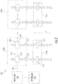
- FIG. 2 illustrates, generally, a system 214 that is operable and/or controllable to control the movement, operation, and/or location of one or more control surfaces 216a...216n of an aircraft (e.g., control surfaces 106, 108, 110). As illustrated in FIG. 2 , the control surfaces 216a...216n are illustrated and controlled by the system 214. Those of skill in the art will appreciate that any number of control surfaces 216a...216n can be controlled and monitored by the system 214, although only two control surfaces 216a, 216n are illustrated in FIG. 2 .
- the control surfaces 216a, 216n can be flaps and/or slats, such as slats 106 and flaps 108 illustrated in FIG. 1 and/or control surfaces 110 located on the tail 112 of the aircraft 100.
- the system 214 includes a controller 218.
- the controller 218 is configured to issue control commands to a drive unit 220.
- the commands can include commands to cause the drive unit 220 to rotate a drive shaft 222 in order to move one or more of the control surfaces 216a, 216n in a desired direction or motion.
- the drive shaft 222 can be rotated to cause one or more of the control surfaces 216a...216n to move in a direction in or out as generally indicated by arrow A.
- the drive shaft 222 may be one or more torque tubes or other similar rods or structures that can convey rotational motion along a length of a wing or other aircraft structure.
- each control surface 216a...216n is operably connected to a dedicated and/or respective actuator unit 224a...224n.
- the drive shaft 222 is schematically shown as interconnecting the various actuators 226, 228 and the various actuator units 224a...224n.
- the various actuators and/or actuator units may be independent and thus not interconnected or other types of connection arrangements are possible without departing from the scope of the present disclosure.
- Each actuator unit 224a...224n includes two actuators operably connected to the respective control surface 216a...216n.
- a first actuator unit 224a includes first and second actuators 226, 228.
- the first actuator 226 includes a first actuator drive unit 230 and a first linear translation element 232.
- the first actuator drive unit 230 receives rotatory motion from the drive shaft 222 and causes the first linear translation element 232 to move linearly in a direction shown generally by arrow A.
- the second actuator 228 includes a second actuator drive unit 234 and a second linear translation element 236.
- the second actuator drive unit 234 also receives rotatory motion from the drive shaft 222 and causes the second linear translation element 236 to move linearly in the direction shown generally by arrow A.
- the linear translation elements 232, 236 are operably connected to respective portions of the first control surface 216a.
- movement of the first linear translation element 232 causes a first portion 217 of the first control surface 216a to move and movement of the second linear translation element 236 causes a second portion 219 of the first control surface 216a to move.
- the first and second portions 217, 219 of the first control surface 216a may be ends or sides of the first control surface 216a and movement thereof adjusts position, angle, tilt, etc. of the control surface 216a to enable flight of an aircraft.
- linear actuators Although shown in FIG. 2 and described above as linear actuators. Those of skill in the art will appreciate that embodiment provided herein can be applied to other type of actuators that are employed to move control surfaces of aircraft. For example, in some embodiments, rotary actuators may be employed using a rack and pinion arrangement.
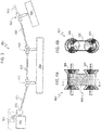
- the control surface operating system 300 is a flight control system for an aircraft (e.g., as shown in FIG. 1 ) that includes a drive system 302 that is operably connected to one or more control surfaces 304.
- the drive system 302 includes a power distribution unit 306 and a transmission 308.
- the power distribution unit 306 drives the transmission 308 to in turn rotate one or more drive shafts 310.
- the rotational movement of the drive shafts 310 is converted to linear movement at one or more actuator units 312 that are operably connected to control surfaces 304.
- the movement of the actuator may be non-linear (e.g., rotary) as will be appreciated by those of skill in the art.
- the power distribution unit 306 can include one or more motors that drive or operate the transmission 308.
- the power distribution unit 306 includes two motors and a speed summing differential gearbox.
- the speed summing differential gearbox is arranged to enable adjusting a driveline speed (e.g., speed of rotation of the drive shaft 310).
- the transmission 308 is operably connected to the gearbox of the power distribution unit 306. In other embodiments, the transmission 308 can be integrated into the gearbox of the power distribution unit 306.
- the drive system 302 includes the power distribution unit 306 and the transmission 308 for enabling operation of the control surfaces 304.
- the transmission 308 is a continuously variable transmission.
- the continuously variable transmission 308 is controllable by a control unit or other controller 309 e.g., by the controller 218 shown in FIG. 2 ).
- the controller can be integral or part of the power distribution unit 306.
- the controller 309 is arranged to control the continuously variable transmission 308 and/or the power distribution unit 306 at one or more predetermined operating ratios such that a desired drive is applied to the drive shafts 310 to achieve a desired operation or movement of the control surfaces 304.
- the controller 309 can be located separate or apart from the drive system 302, but operably connected or in communication therewith.
- FIGS. 4A-4B a non-limiting example of a portion of a continuously variable transmission 400 in accordance with an embodiment of the present disclosure is schematically shown.
- FIG. 4A is a plan schematic illustration of a transmission belt 402 that is driven by conical gear sets 404, 406, and
- FIG. 4B is a view along the line B-B shown in FIG. 4A . That is, the continuously variable transmission 400 includes a combination of multiple conical gear sets 404, 406 attached with a belt 402 that allows variable ratio from input to output speed ratio applied to a power distribution unit of a control panel operating system, as shown and described above.
- the continuously variable transmission of the control surface operating system can be operated at a first gear or speed for extension or deployment operations of the control surface(s) and at a second gear or speed that is different from the first gear or speed for retraction operations of the control surface(s).
- the different operating gears of the continuously variable transmission can be optimized to perform specific operations at specific loads and/or flight conditions. For example, during a take-off operation of an aircraft, the control surfaces of the aircraft are typically extended to generate lift, and thus high loads may be applied to the control surfaces, and as such a specific motor operating speed should be employed.
- the continuously variable transmission of the present disclosure enables operating at different speeds that are predefined for specific load conditions, operating functions (e.g., extension/retraction of control surfaces), based on demand of a pilot, etc. That is, the continuously variable transmission of embodiments of the present disclosure can be controlled based on a flight condition (e.g., take-off, ascent, cruise, descent, landing, etc.).
- a flight condition e.g., take-off, ascent, cruise, descent, landing, etc.
- a high-driveline and motor torque aircraft condition for the wing high lift system occurs when the aircraft is operating near a maximum airspeed condition after a long flight at cold temperature.
- the tare losses within the actuators in combination with the high aerodynamic wing loads that are driven by the actuation system cascade through the driveline back to the power drive unit.
- the aircraft may require very quick response from the actuation system to stow flap and slat panels (aerodynamic control surfaces) following a take-off with a short distance requiring a high rate of climb.
- the aircraft may need to change panel configuration to stow the slat and flap panels quickly with low magnitude tare and aerodynamic loads (potentially even aiding aerodynamic loads).
- Such external loading situations may be very conducive to a multi-geared transmission or continuously variable transmission because the high speed could be achieved by an efficient change in gearing rather than designing an oversized power drive unit and associated inefficient power draw to the aircraft.
- a similar situation can occur when the aircraft is on the ground with near zero aerodynamic loads and the system enables reconfiguration more rapidly to desired panel positions, either stowed or deployed to a take-off position, as compared to traditional systems.
- an electronic control unit of the aircraft could employ feedback from the aircraft with respect to these parameters (airspeed, altitude) to determine an optimal speed to run the continuously variable transmission to meet both optimal transit times (high speed) as well as deploy under extreme loading conditions (low speed).
- embodiments provided herein are directed to control surface operating systems for aircraft that include continuously variable transmissions.
- the transmission When installing a typical system (single gear system), the transmission is set to operate at a specific speed such that one of deploying or retracting is optimized.
- the other of the deploying or retracting is not optimized for rotational speed, and thus inefficiencies will be present. That is, with traditional systems, torque speed curves must be optimized for a given speed. Operation that tries to achieve multiple torque/speed operational points is not optimized for electromagnetics.
- Usage of a continuously variable transmission as provided herein, enables optimum performance of the motor magnetics while providing wide range of available operational speeds.
Landscapes
- Engineering & Computer Science (AREA)
- Automation & Control Theory (AREA)
- Aviation & Aerospace Engineering (AREA)
- Mechanical Engineering (AREA)
- Transmission Devices (AREA)
Claims (15)
- Steuerflächenbetriebssystem (300) zum Steuern von aerodynamischen Steuerflächen eines Flugzeugs, wobei das System Folgendes umfasst:ein Antriebssystem (302), das mit einer Antriebswelle (310) wirkverbunden ist, wobei das Antriebssystem ein kontinuierlich variables Getriebe (308, 400) beinhaltet;zumindest einen Aktuator, der mit der Antriebswelle (310) wirkverbunden und angeordnet ist, um Drehbewegung der Antriebswelle (310) umzuwandeln, um zumindest einen Abschnitt der aerodynamischen Steuerfläche zu bewegen; undzumindest eine Steuerfläche, die mit dem zumindest einen Aktuator wirkverbunden ist, wobei die zumindest eine Steuerfläche durch den zumindest einen Aktuator eingestellt wird;dadurch gekennzeichnet, dass das kontinuierlich variable Getriebe (308, 400) zumindest zwei konische Zahnradsätze (404, 406) beinhaltet, um variable Übersetzungsverhältnisse des kontinuierlich variablen Getriebes (308, 400) zu ermöglichen.
- Steuerflächenbetriebssystem nach Anspruch 1, wobei die zumindest eine Steuerfläche mit zwei Aktuatoren wirkverbunden ist.
- Steuerflächenbetriebssystem nach einem vorhergehenden Anspruch, wobei das Antriebssystem (310) eine Leistungsverteilungseinheit (302) beinhaltet, die angeordnet ist, um das kontinuierlich variable Getriebe (308, 400) anzutreiben.
- Steuerflächenbetriebssystem nach einem vorhergehenden Anspruch, ferner umfassend eine Steuerung (309), die angeordnet ist, um den Betrieb des kontinuierlich variablen Getriebes (308, 400) zu steuern, wobei die Steuerung (309) Teil des Antriebssystems ist, und/oder wobei die Steuerung den Betrieb des kontinuierlich variablen Getriebes basierend auf einem Flugzustand des Flugzeugs steuert.
- Steuerflächenbetriebssystem nach einem vorhergehenden Anspruch, wobei die zumindest eine Steuerfläche eines von einer Klappe oder einer Lamelle an einem Flügel oder einem Heck des Flugzeugs ist.
- Steuerflächenbetriebssystem nach einem vorhergehenden Anspruch, wobei ein Riemen (402) durch die zumindest zwei konischen Zahnradsätze angetrieben wird.
- Steuerflächenbetriebssystem nach einem vorhergehenden Anspruch, wobei die Antriebswelle (310) zumindest eine Hohlwelle umfasst, wobei die Antriebswelle mehrere Hohlwellen umfasst, die eine Vielzahl von Aktuatoren wirkverbinden, wobei die Vielzahl von Aktuatoren angeordnet ist, um den Betrieb von zumindest zwei Steuerflächen zu steuern.
- Steuerflächenbetriebssystem nach einem vorhergehenden Anspruch, wobei der zumindest eine Aktuator ein linearer Aktuator ist.
- Steuerflächenbetriebssystem nach einem vorhergehenden Anspruch, wobei der zumindest eine Aktuator ein Drehaktuator ist.
- Flugzeug, umfassend:zumindest eine aerodynamische Steuerfläche; unddas Steuerflächenbetriebssystem nach einem vorhergehenden Anspruch, um den Betrieb der zumindest einen aerodynamischen Steuerfläche des Flugzeugs zu steuern.
- Flugzeug nach Anspruch 10, wobei das Antriebssystem zumindest eines von einer Leistungsverteilungseinheit (302), die angeordnet ist, um das kontinuierlich variable Getriebe (308, 400) anzutreiben, und einer Steuerung (309) beinhaltet, die angeordnet ist, um den Betrieb des kontinuierlich variablen Getriebes (308, 400) zu steuern, wobei die Steuerung (309) konfiguriert ist, um den Betrieb des kontinuierlich variablen Getriebes (308, 400) basierend auf einem Flugzustand des Flugzeugs zu steuern.
- Flugzeug nach einem der Ansprüche 10-11, wobei die zumindest eine Steuerfläche eines von einer Klappe oder einer Lamelle an einem Flügel oder einem Heck des Flugzeugs ist.
- Flugzeug nach einem der Ansprüche 10-12, wobei die Antriebswelle (310) mehrere Hohlwellen umfasst, die eine Vielzahl von Aktuatoren wirkverbinden, wobei die Vielzahl von Aktuatoren angeordnet ist, um den Betrieb von zumindest zwei Steuerflächen des Flugzeugs zu steuern.
- Verfahren zum Steuern des Betriebs von aerodynamischen Steuerflächen eines Flugzeugs, wobei das Verfahren Folgendes umfasst:Antreiben einer Antriebswelle (309) mit einem kontinuierlich variablen Getriebe, wobei die Antriebswelle (309) mit zumindest einem Aktuator wirkgekoppelt ist; undUmwandeln von Drehbewegung der Antriebswelle (309) unter Verwendung des zumindest einen Aktuators, um zumindest einen Abschnitt der aerodynamischen Steuerfläche zu bewegen, um die aerodynamische Steuerfläche einzustellen; dadurch gekennzeichnet, dass das kontinuierlich variable Getriebe (308, 400) zumindest zwei konische Zahnradsätze (404, 406) beinhaltet, um variable Übersetzungsverhältnisse des kontinuierlich variablen Getriebes (308, 400) zu ermöglichen.
- Verfahren nach Anspruch 14, ferner umfassend das Steuern des Betriebs des kontinuierlich variablen Getriebes (308, 400) basierend auf einem Flugzustand des Flugzeugs.
Applications Claiming Priority (1)
| Application Number | Priority Date | Filing Date | Title |
|---|---|---|---|
| US15/654,963 US10696380B2 (en) | 2017-07-20 | 2017-07-20 | Aerodynamic control surface operating system for aircraft using variable transmission |
Publications (2)
| Publication Number | Publication Date |
|---|---|
| EP3431391A1 EP3431391A1 (de) | 2019-01-23 |
| EP3431391B1 true EP3431391B1 (de) | 2020-10-28 |
Family
ID=63012873
Family Applications (1)
| Application Number | Title | Priority Date | Filing Date |
|---|---|---|---|
| EP18184399.6A Active EP3431391B1 (de) | 2017-07-20 | 2018-07-19 | Betriebssystem für aerodynamische steuerflächen für ein flugzeug unter verwendung eines variablen getriebes |
Country Status (2)
| Country | Link |
|---|---|
| US (1) | US10696380B2 (de) |
| EP (1) | EP3431391B1 (de) |
Families Citing this family (6)
| Publication number | Priority date | Publication date | Assignee | Title |
|---|---|---|---|---|
| US10696380B2 (en) * | 2017-07-20 | 2020-06-30 | Hamilton Sunstrand Corporation | Aerodynamic control surface operating system for aircraft using variable transmission |
| US11548620B2 (en) | 2019-03-11 | 2023-01-10 | Parker-Hannifin Corporation | Electromechanically actuated control rod for flight vehicles |
| EP4029775B1 (de) * | 2021-01-15 | 2025-07-30 | Claverham Limited | Betätigungssystem |
| US11897602B2 (en) | 2021-03-17 | 2024-02-13 | The Boeing Company | Support structure for an aircraft landing gear |
| EP4393815A1 (de) * | 2022-12-30 | 2024-07-03 | Airbus Operations GmbH | Flugzeugklappensystem |
| US12330771B2 (en) | 2023-10-31 | 2025-06-17 | Honeywell International Inc. | Differential lock actuator systems and methods for moving flight control surface |
Family Cites Families (45)
| Publication number | Priority date | Publication date | Assignee | Title |
|---|---|---|---|---|
| US2175584A (en) * | 1935-05-21 | 1939-10-10 | Sperry Gyroscope Co Inc | Variable ratio manual controller for aircraft |
| US2796774A (en) * | 1952-05-03 | 1957-06-25 | North American Aviation Inc | Control system ratio shift mechanism |
| US2941638A (en) * | 1953-04-04 | 1960-06-21 | Vaino A Hoover | Mechanical actuator interlocking system |
| US2873833A (en) * | 1954-11-29 | 1959-02-17 | Cleveland Pneumatic Ind Inc | Overrunning clutch |
| US2931928A (en) * | 1956-08-30 | 1960-04-05 | Bliss E W Co | Torque transmitting mechanism |
| US2893258A (en) * | 1956-11-16 | 1959-07-07 | Gen Motors Corp | Mechanical movement device |
| US3043539A (en) | 1960-01-08 | 1962-07-10 | Bendix Corp | Control stick torque sensor to selectively effect autopilot and manual control of aircraft control surfaces |
| FR2146166B1 (de) * | 1971-07-22 | 1974-08-19 | Gerard Andre | |
| US3773282A (en) * | 1971-12-27 | 1973-11-20 | Mc Donnell Douglas Corp | Vehicle control system |
| US4318304A (en) * | 1980-04-11 | 1982-03-09 | Sundstrand Corporation | Force limiting device |
| US4362067A (en) * | 1980-08-21 | 1982-12-07 | The Garrett Corporation | Variable authority trim mixer |
| GB2069426B (en) | 1981-01-22 | 1983-12-21 | Messerschmitt Boelkow Blohm | Aircraft control mechanism |
| US4401077A (en) * | 1981-04-17 | 1983-08-30 | The Garrett Corporation | Throttle linkage control |
| US4466520A (en) * | 1981-12-07 | 1984-08-21 | International Business Machines Corporation | Self-contained clutch useful for single revolution applications |
| US4595158A (en) * | 1983-09-26 | 1986-06-17 | The Boeing Company | Aircraft control surface actuation and counterbalancing |
| DE3566324D1 (en) * | 1984-12-03 | 1988-12-22 | Bbc Brown Boveri & Cie | Driving device for a switch |
| US4817452A (en) * | 1987-03-11 | 1989-04-04 | Burkey Ronald L | Force and throw transformer for actuation linkages |
| US4858691A (en) * | 1988-06-13 | 1989-08-22 | Baker Hughes Incorporated | Gravel packing apparatus and method |
| GB8918431D0 (en) * | 1989-08-12 | 1989-09-20 | Lucas Ind Plc | Apparatus for aircraft flight |
| US5518466A (en) * | 1994-11-29 | 1996-05-21 | Curtiss Wright Flight Systems Inc. | Jam-tolerant rotary actuator |
| US5628234A (en) * | 1995-10-30 | 1997-05-13 | Gec-Marconi Aerospace Inc. | Fail-free actuator assembly |
| FR2778164B1 (fr) * | 1998-04-29 | 2000-06-23 | Aerospatiale | Systeme de commande mixte pour surface aerodynamique d'aeronef |
| JP3266152B2 (ja) * | 1999-03-31 | 2002-03-18 | 株式会社デンソー | リンクレバー装置およびそれを用いた車両用空調装置 |
| DE10019185C2 (de) * | 2000-04-17 | 2003-06-05 | Airbus Gmbh | Anordnung zur aerodynamischen Lärmminderung von Vorflügeln eines Verkehrsflugzeuges |
| US7134672B2 (en) * | 2001-07-19 | 2006-11-14 | Stoneridge Control Devices, Inc. | Failsafe actuator |
| US20050252318A1 (en) * | 2003-09-05 | 2005-11-17 | Bae Systems Plc | Apparatus for releasing a jam in a lead screw actuator |
| JP4499620B2 (ja) * | 2005-06-16 | 2010-07-07 | 本田技研工業株式会社 | 車両用変速操作装置 |
| FR2913267B1 (fr) * | 2007-03-01 | 2009-10-02 | Valeo Systemes Thermiques | Dispositif de detection de temperature pour habitacle de vehicule |
| US8002216B2 (en) * | 2007-06-15 | 2011-08-23 | Darwin Kent Decker | Solar powered wing vehicle using flywheels for energy storage |
| US8725371B2 (en) * | 2009-03-05 | 2014-05-13 | Toyota Jidosha Kabushiki Kaisha | Speed changing control apparatus for vehicle |
| US8967007B2 (en) * | 2009-04-26 | 2015-03-03 | William Terry Lester | Continuously variable transmission using oscillating torque and timing belt or timing chain constrained masses |
| US8534610B1 (en) * | 2009-07-17 | 2013-09-17 | The Boeing Company | Method and apparatus for a leading edge slat on a wing of an aircraft |
| DE102010026619B4 (de) * | 2010-07-09 | 2018-11-15 | Airbus Operations Gmbh | Vorflügel mit flexibler Hinterkante |
| US20130193263A1 (en) * | 2010-07-23 | 2013-08-01 | Samuel Adam Schweighart | Roadable aircraft and related systems |
| US9242720B2 (en) * | 2010-10-21 | 2016-01-26 | The United States Of America As Represented By The Administrator Of The National Aeronautics And Space Administration | Autonomous slat-cove-filler device for reduction of aeroacoustic noise associated with aircraft systems |
| US8690099B2 (en) * | 2010-11-16 | 2014-04-08 | Rolls-Royce Corporation | Aircraft and propulsion system |
| US9328661B2 (en) * | 2011-11-03 | 2016-05-03 | Northrop Grumman Systems Corporation | Apparatus for aircraft with high peak power equipment |
| US8839926B2 (en) * | 2012-03-30 | 2014-09-23 | General Electric Company | Jam tolerant actuator decoupler |
| JP6396006B2 (ja) * | 2013-08-30 | 2018-09-26 | ナブテスコ株式会社 | 航空機用電動アクチュエータ駆動装置 |
| EP2902314B1 (de) | 2014-01-29 | 2017-07-19 | Airbus Operations GmbH | Hochauftriebssystem für ein Flugzeug und Flugzeug mit einem solchen Hochauftriebssystem |
| ZA201402532B (en) | 2014-04-08 | 2015-03-25 | Michael Daniel Buguma | A propulsion arrangement |
| JP6554282B2 (ja) * | 2014-12-24 | 2019-07-31 | 川崎重工業株式会社 | 航空機用エンジン装置 |
| US10088006B2 (en) * | 2016-05-19 | 2018-10-02 | The Boeing Company | Rotational inerter and method for damping an actuator |
| US10107347B2 (en) * | 2016-05-19 | 2018-10-23 | The Boeing Company | Dual rack and pinion rotational inerter system and method for damping movement of a flight control surface of an aircraft |
| US10696380B2 (en) * | 2017-07-20 | 2020-06-30 | Hamilton Sunstrand Corporation | Aerodynamic control surface operating system for aircraft using variable transmission |
-
2017
- 2017-07-20 US US15/654,963 patent/US10696380B2/en active Active
-
2018
- 2018-07-19 EP EP18184399.6A patent/EP3431391B1/de active Active
Non-Patent Citations (1)
| Title |
|---|
| None * |
Also Published As
| Publication number | Publication date |
|---|---|
| US20190023378A1 (en) | 2019-01-24 |
| EP3431391A1 (de) | 2019-01-23 |
| US10696380B2 (en) | 2020-06-30 |
Similar Documents
| Publication | Publication Date | Title |
|---|---|---|
| EP3431391B1 (de) | Betriebssystem für aerodynamische steuerflächen für ein flugzeug unter verwendung eines variablen getriebes | |
| EP1786667B2 (de) | Systeme und verfahren zur bereitstellung von differenzieller bewegung für flügelhochauftriebsvorrichtungen | |
| EP2902314B1 (de) | Hochauftriebssystem für ein Flugzeug und Flugzeug mit einem solchen Hochauftriebssystem | |
| US10899431B2 (en) | System for driving and guiding of a multifunctional trailing edge control surface on an aircraft | |
| CA2976237C (en) | Tilting ducted fan aircraft generating a pitch control moment | |
| US8544793B1 (en) | Adjustable angle inlet for turbojet engines | |
| EP0937641B1 (de) | Flugzeugsteuerungseinrichtungen mit automatischer Kompensation | |
| EP3040548B1 (de) | Flugzeug mit gegenläufigen mantelstrom-triebwerken | |
| US11174006B2 (en) | High-lift actuation system with clutch architecture | |
| WO2022140135A1 (en) | Systems and methods for aircraft lift enhancement | |
| WO2010119280A1 (en) | High lift devices for aircraft | |
| US20150037149A1 (en) | Rotorcraft control system for rotorcraft with two or more rotor systems | |
| EP2851289B1 (de) | Vorder- und Hinterkantenvorrichtungswinkeln während des Sinkfluges eines Flugzeuges | |
| KR20140079174A (ko) | 프로펠러 블레이드 피치조절장치 | |
| EP3290749B1 (de) | Aktuatoren für hochhubvorrichtungen eines flugzeugs | |
| US20160304195A1 (en) | Mission flexible, engine flexible, asymmetric vertical take-off and landing (vtol) aircraft | |
| EP3279508B1 (de) | Kraftantriebseinheit mit dualem getriebeübersetzungsmechanismus | |
| EP3736213A1 (de) | Hybrides unbemanntes luftfahrzeug | |
| KR101529856B1 (ko) | 헬리콥터식 비행체 | |
| CN109911240B (zh) | 满足旋转机翼飞机高低速巡航要求的设计与控制方法及实现装置 | |
| US8746623B2 (en) | Method and device for generating an optimum aerodynamic configuration of an aircraft during a flight | |
| EP0937642A2 (de) | Flugzeugsteuerungseinrichtungen mit automatischer Kompensation | |
| EP3858728B1 (de) | Klappenbetätigungsanordnung | |
| IL318492A (en) | Pivoting wing as a pivoting wing with partial profiles with partial profiles that can be rotated on a pivot |
Legal Events
| Date | Code | Title | Description |
|---|---|---|---|
| PUAI | Public reference made under article 153(3) epc to a published international application that has entered the european phase |
Free format text: ORIGINAL CODE: 0009012 |
|
| STAA | Information on the status of an ep patent application or granted ep patent |
Free format text: STATUS: THE APPLICATION HAS BEEN PUBLISHED |
|
| AK | Designated contracting states |
Kind code of ref document: A1 Designated state(s): AL AT BE BG CH CY CZ DE DK EE ES FI FR GB GR HR HU IE IS IT LI LT LU LV MC MK MT NL NO PL PT RO RS SE SI SK SM TR |
|
| AX | Request for extension of the european patent |
Extension state: BA ME |
|
| RIN1 | Information on inventor provided before grant (corrected) |
Inventor name: BISHOP, YUNIYA S. Inventor name: HARRINGTON, ERIK Inventor name: MILLER, CHRISTIAN |
|
| STAA | Information on the status of an ep patent application or granted ep patent |
Free format text: STATUS: REQUEST FOR EXAMINATION WAS MADE |
|
| 17P | Request for examination filed |
Effective date: 20190722 |
|
| RBV | Designated contracting states (corrected) |
Designated state(s): AL AT BE BG CH CY CZ DE DK EE ES FI FR GB GR HR HU IE IS IT LI LT LU LV MC MK MT NL NO PL PT RO RS SE SI SK SM TR |
|
| GRAP | Despatch of communication of intention to grant a patent |
Free format text: ORIGINAL CODE: EPIDOSNIGR1 |
|
| STAA | Information on the status of an ep patent application or granted ep patent |
Free format text: STATUS: GRANT OF PATENT IS INTENDED |
|
| INTG | Intention to grant announced |
Effective date: 20200525 |
|
| GRAS | Grant fee paid |
Free format text: ORIGINAL CODE: EPIDOSNIGR3 |
|
| GRAA | (expected) grant |
Free format text: ORIGINAL CODE: 0009210 |
|
| STAA | Information on the status of an ep patent application or granted ep patent |
Free format text: STATUS: THE PATENT HAS BEEN GRANTED |
|
| AK | Designated contracting states |
Kind code of ref document: B1 Designated state(s): AL AT BE BG CH CY CZ DE DK EE ES FI FR GB GR HR HU IE IS IT LI LT LU LV MC MK MT NL NO PL PT RO RS SE SI SK SM TR |
|
| REG | Reference to a national code |
Ref country code: GB Ref legal event code: FG4D |
|
| REG | Reference to a national code |
Ref country code: CH Ref legal event code: EP |
|
| REG | Reference to a national code |
Ref country code: AT Ref legal event code: REF Ref document number: 1327968 Country of ref document: AT Kind code of ref document: T Effective date: 20201115 |
|
| REG | Reference to a national code |
Ref country code: DE Ref legal event code: R096 Ref document number: 602018009074 Country of ref document: DE |
|
| REG | Reference to a national code |
Ref country code: IE Ref legal event code: FG4D |
|
| REG | Reference to a national code |
Ref country code: AT Ref legal event code: MK05 Ref document number: 1327968 Country of ref document: AT Kind code of ref document: T Effective date: 20201028 |
|
| REG | Reference to a national code |
Ref country code: NL Ref legal event code: MP Effective date: 20201028 |
|
| PG25 | Lapsed in a contracting state [announced via postgrant information from national office to epo] |
Ref country code: PT Free format text: LAPSE BECAUSE OF FAILURE TO SUBMIT A TRANSLATION OF THE DESCRIPTION OR TO PAY THE FEE WITHIN THE PRESCRIBED TIME-LIMIT Effective date: 20210301 Ref country code: RS Free format text: LAPSE BECAUSE OF FAILURE TO SUBMIT A TRANSLATION OF THE DESCRIPTION OR TO PAY THE FEE WITHIN THE PRESCRIBED TIME-LIMIT Effective date: 20201028 Ref country code: FI Free format text: LAPSE BECAUSE OF FAILURE TO SUBMIT A TRANSLATION OF THE DESCRIPTION OR TO PAY THE FEE WITHIN THE PRESCRIBED TIME-LIMIT Effective date: 20201028 Ref country code: GR Free format text: LAPSE BECAUSE OF FAILURE TO SUBMIT A TRANSLATION OF THE DESCRIPTION OR TO PAY THE FEE WITHIN THE PRESCRIBED TIME-LIMIT Effective date: 20210129 Ref country code: NO Free format text: LAPSE BECAUSE OF FAILURE TO SUBMIT A TRANSLATION OF THE DESCRIPTION OR TO PAY THE FEE WITHIN THE PRESCRIBED TIME-LIMIT Effective date: 20210128 |
|
| REG | Reference to a national code |
Ref country code: LT Ref legal event code: MG4D |
|
| PG25 | Lapsed in a contracting state [announced via postgrant information from national office to epo] |
Ref country code: BG Free format text: LAPSE BECAUSE OF FAILURE TO SUBMIT A TRANSLATION OF THE DESCRIPTION OR TO PAY THE FEE WITHIN THE PRESCRIBED TIME-LIMIT Effective date: 20210128 Ref country code: SE Free format text: LAPSE BECAUSE OF FAILURE TO SUBMIT A TRANSLATION OF THE DESCRIPTION OR TO PAY THE FEE WITHIN THE PRESCRIBED TIME-LIMIT Effective date: 20201028 Ref country code: PL Free format text: LAPSE BECAUSE OF FAILURE TO SUBMIT A TRANSLATION OF THE DESCRIPTION OR TO PAY THE FEE WITHIN THE PRESCRIBED TIME-LIMIT Effective date: 20201028 Ref country code: LV Free format text: LAPSE BECAUSE OF FAILURE TO SUBMIT A TRANSLATION OF THE DESCRIPTION OR TO PAY THE FEE WITHIN THE PRESCRIBED TIME-LIMIT Effective date: 20201028 Ref country code: IS Free format text: LAPSE BECAUSE OF FAILURE TO SUBMIT A TRANSLATION OF THE DESCRIPTION OR TO PAY THE FEE WITHIN THE PRESCRIBED TIME-LIMIT Effective date: 20210228 Ref country code: AT Free format text: LAPSE BECAUSE OF FAILURE TO SUBMIT A TRANSLATION OF THE DESCRIPTION OR TO PAY THE FEE WITHIN THE PRESCRIBED TIME-LIMIT Effective date: 20201028 Ref country code: ES Free format text: LAPSE BECAUSE OF FAILURE TO SUBMIT A TRANSLATION OF THE DESCRIPTION OR TO PAY THE FEE WITHIN THE PRESCRIBED TIME-LIMIT Effective date: 20201028 |
|
| PG25 | Lapsed in a contracting state [announced via postgrant information from national office to epo] |
Ref country code: HR Free format text: LAPSE BECAUSE OF FAILURE TO SUBMIT A TRANSLATION OF THE DESCRIPTION OR TO PAY THE FEE WITHIN THE PRESCRIBED TIME-LIMIT Effective date: 20201028 Ref country code: NL Free format text: LAPSE BECAUSE OF FAILURE TO SUBMIT A TRANSLATION OF THE DESCRIPTION OR TO PAY THE FEE WITHIN THE PRESCRIBED TIME-LIMIT Effective date: 20201028 |
|
| REG | Reference to a national code |
Ref country code: DE Ref legal event code: R097 Ref document number: 602018009074 Country of ref document: DE |
|
| PG25 | Lapsed in a contracting state [announced via postgrant information from national office to epo] |
Ref country code: SM Free format text: LAPSE BECAUSE OF FAILURE TO SUBMIT A TRANSLATION OF THE DESCRIPTION OR TO PAY THE FEE WITHIN THE PRESCRIBED TIME-LIMIT Effective date: 20201028 Ref country code: EE Free format text: LAPSE BECAUSE OF FAILURE TO SUBMIT A TRANSLATION OF THE DESCRIPTION OR TO PAY THE FEE WITHIN THE PRESCRIBED TIME-LIMIT Effective date: 20201028 Ref country code: CZ Free format text: LAPSE BECAUSE OF FAILURE TO SUBMIT A TRANSLATION OF THE DESCRIPTION OR TO PAY THE FEE WITHIN THE PRESCRIBED TIME-LIMIT Effective date: 20201028 Ref country code: LT Free format text: LAPSE BECAUSE OF FAILURE TO SUBMIT A TRANSLATION OF THE DESCRIPTION OR TO PAY THE FEE WITHIN THE PRESCRIBED TIME-LIMIT Effective date: 20201028 Ref country code: RO Free format text: LAPSE BECAUSE OF FAILURE TO SUBMIT A TRANSLATION OF THE DESCRIPTION OR TO PAY THE FEE WITHIN THE PRESCRIBED TIME-LIMIT Effective date: 20201028 Ref country code: SK Free format text: LAPSE BECAUSE OF FAILURE TO SUBMIT A TRANSLATION OF THE DESCRIPTION OR TO PAY THE FEE WITHIN THE PRESCRIBED TIME-LIMIT Effective date: 20201028 |
|
| PG25 | Lapsed in a contracting state [announced via postgrant information from national office to epo] |
Ref country code: DK Free format text: LAPSE BECAUSE OF FAILURE TO SUBMIT A TRANSLATION OF THE DESCRIPTION OR TO PAY THE FEE WITHIN THE PRESCRIBED TIME-LIMIT Effective date: 20201028 |
|
| PLBE | No opposition filed within time limit |
Free format text: ORIGINAL CODE: 0009261 |
|
| STAA | Information on the status of an ep patent application or granted ep patent |
Free format text: STATUS: NO OPPOSITION FILED WITHIN TIME LIMIT |
|
| 26N | No opposition filed |
Effective date: 20210729 |
|
| PG25 | Lapsed in a contracting state [announced via postgrant information from national office to epo] |
Ref country code: IT Free format text: LAPSE BECAUSE OF FAILURE TO SUBMIT A TRANSLATION OF THE DESCRIPTION OR TO PAY THE FEE WITHIN THE PRESCRIBED TIME-LIMIT Effective date: 20201028 Ref country code: AL Free format text: LAPSE BECAUSE OF FAILURE TO SUBMIT A TRANSLATION OF THE DESCRIPTION OR TO PAY THE FEE WITHIN THE PRESCRIBED TIME-LIMIT Effective date: 20201028 |
|
| PG25 | Lapsed in a contracting state [announced via postgrant information from national office to epo] |
Ref country code: SI Free format text: LAPSE BECAUSE OF FAILURE TO SUBMIT A TRANSLATION OF THE DESCRIPTION OR TO PAY THE FEE WITHIN THE PRESCRIBED TIME-LIMIT Effective date: 20201028 |
|
| REG | Reference to a national code |
Ref country code: CH Ref legal event code: PL |
|
| PG25 | Lapsed in a contracting state [announced via postgrant information from national office to epo] |
Ref country code: MC Free format text: LAPSE BECAUSE OF FAILURE TO SUBMIT A TRANSLATION OF THE DESCRIPTION OR TO PAY THE FEE WITHIN THE PRESCRIBED TIME-LIMIT Effective date: 20201028 |
|
| REG | Reference to a national code |
Ref country code: BE Ref legal event code: MM Effective date: 20210731 |
|
| PG25 | Lapsed in a contracting state [announced via postgrant information from national office to epo] |
Ref country code: LI Free format text: LAPSE BECAUSE OF NON-PAYMENT OF DUE FEES Effective date: 20210731 Ref country code: CH Free format text: LAPSE BECAUSE OF NON-PAYMENT OF DUE FEES Effective date: 20210731 |
|
| PG25 | Lapsed in a contracting state [announced via postgrant information from national office to epo] |
Ref country code: IS Free format text: LAPSE BECAUSE OF FAILURE TO SUBMIT A TRANSLATION OF THE DESCRIPTION OR TO PAY THE FEE WITHIN THE PRESCRIBED TIME-LIMIT Effective date: 20210228 Ref country code: LU Free format text: LAPSE BECAUSE OF NON-PAYMENT OF DUE FEES Effective date: 20210719 |
|
| PG25 | Lapsed in a contracting state [announced via postgrant information from national office to epo] |
Ref country code: IE Free format text: LAPSE BECAUSE OF NON-PAYMENT OF DUE FEES Effective date: 20210719 Ref country code: BE Free format text: LAPSE BECAUSE OF NON-PAYMENT OF DUE FEES Effective date: 20210731 |
|
| P01 | Opt-out of the competence of the unified patent court (upc) registered |
Effective date: 20230522 |
|
| PG25 | Lapsed in a contracting state [announced via postgrant information from national office to epo] |
Ref country code: CY Free format text: LAPSE BECAUSE OF FAILURE TO SUBMIT A TRANSLATION OF THE DESCRIPTION OR TO PAY THE FEE WITHIN THE PRESCRIBED TIME-LIMIT Effective date: 20201028 |
|
| PG25 | Lapsed in a contracting state [announced via postgrant information from national office to epo] |
Ref country code: HU Free format text: LAPSE BECAUSE OF FAILURE TO SUBMIT A TRANSLATION OF THE DESCRIPTION OR TO PAY THE FEE WITHIN THE PRESCRIBED TIME-LIMIT; INVALID AB INITIO Effective date: 20180719 |
|
| PG25 | Lapsed in a contracting state [announced via postgrant information from national office to epo] |
Ref country code: MK Free format text: LAPSE BECAUSE OF FAILURE TO SUBMIT A TRANSLATION OF THE DESCRIPTION OR TO PAY THE FEE WITHIN THE PRESCRIBED TIME-LIMIT Effective date: 20201028 |
|
| PG25 | Lapsed in a contracting state [announced via postgrant information from national office to epo] |
Ref country code: TR Free format text: LAPSE BECAUSE OF FAILURE TO SUBMIT A TRANSLATION OF THE DESCRIPTION OR TO PAY THE FEE WITHIN THE PRESCRIBED TIME-LIMIT Effective date: 20201028 |
|
| PG25 | Lapsed in a contracting state [announced via postgrant information from national office to epo] |
Ref country code: MT Free format text: LAPSE BECAUSE OF FAILURE TO SUBMIT A TRANSLATION OF THE DESCRIPTION OR TO PAY THE FEE WITHIN THE PRESCRIBED TIME-LIMIT Effective date: 20201028 |
|
| PGFP | Annual fee paid to national office [announced via postgrant information from national office to epo] |
Ref country code: GB Payment date: 20250619 Year of fee payment: 8 |
|
| PGFP | Annual fee paid to national office [announced via postgrant information from national office to epo] |
Ref country code: FR Payment date: 20250620 Year of fee payment: 8 |
|
| PGFP | Annual fee paid to national office [announced via postgrant information from national office to epo] |
Ref country code: DE Payment date: 20250620 Year of fee payment: 8 |