EP3431631A1 - Abreibbare suspensionsplasmaspritzschicht für einen freitragenden stator - Google Patents
Abreibbare suspensionsplasmaspritzschicht für einen freitragenden stator Download PDFInfo
- Publication number
- EP3431631A1 EP3431631A1 EP18185030.6A EP18185030A EP3431631A1 EP 3431631 A1 EP3431631 A1 EP 3431631A1 EP 18185030 A EP18185030 A EP 18185030A EP 3431631 A1 EP3431631 A1 EP 3431631A1
- Authority
- EP
- European Patent Office
- Prior art keywords
- coating
- stabilized zirconia
- yttria
- zirconia
- abradable coating
- Prior art date
- Legal status (The legal status is an assumption and is not a legal conclusion. Google has not performed a legal analysis and makes no representation as to the accuracy of the status listed.)
- Granted
Links
Images


Classifications
-
- F—MECHANICAL ENGINEERING; LIGHTING; HEATING; WEAPONS; BLASTING
- F01—MACHINES OR ENGINES IN GENERAL; ENGINE PLANTS IN GENERAL; STEAM ENGINES
- F01D—NON-POSITIVE DISPLACEMENT MACHINES OR ENGINES, e.g. STEAM TURBINES
- F01D5/00—Blades; Blade-carrying members; Heating, heat-insulating, cooling or antivibration means on the blades or the members
- F01D5/02—Blade-carrying members, e.g. rotors
-
- C—CHEMISTRY; METALLURGY
- C23—COATING METALLIC MATERIAL; COATING MATERIAL WITH METALLIC MATERIAL; CHEMICAL SURFACE TREATMENT; DIFFUSION TREATMENT OF METALLIC MATERIAL; COATING BY VACUUM EVAPORATION, BY SPUTTERING, BY ION IMPLANTATION OR BY CHEMICAL VAPOUR DEPOSITION, IN GENERAL; INHIBITING CORROSION OF METALLIC MATERIAL OR INCRUSTATION IN GENERAL
- C23C—COATING METALLIC MATERIAL; COATING MATERIAL WITH METALLIC MATERIAL; SURFACE TREATMENT OF METALLIC MATERIAL BY DIFFUSION INTO THE SURFACE, BY CHEMICAL CONVERSION OR SUBSTITUTION; COATING BY VACUUM EVAPORATION, BY SPUTTERING, BY ION IMPLANTATION OR BY CHEMICAL VAPOUR DEPOSITION, IN GENERAL
- C23C28/00—Coating for obtaining at least two superposed coatings either by methods not provided for in a single one of groups C23C2/00 - C23C26/00 or by combinations of methods provided for in subclasses C23C and C25C or C25D
- C23C28/04—Coating for obtaining at least two superposed coatings either by methods not provided for in a single one of groups C23C2/00 - C23C26/00 or by combinations of methods provided for in subclasses C23C and C25C or C25D only coatings of inorganic non-metallic material
- C23C28/042—Coating for obtaining at least two superposed coatings either by methods not provided for in a single one of groups C23C2/00 - C23C26/00 or by combinations of methods provided for in subclasses C23C and C25C or C25D only coatings of inorganic non-metallic material including a refractory ceramic layer, e.g. refractory metal oxides, ZrO2, rare earth oxides
-
- C—CHEMISTRY; METALLURGY
- C23—COATING METALLIC MATERIAL; COATING MATERIAL WITH METALLIC MATERIAL; CHEMICAL SURFACE TREATMENT; DIFFUSION TREATMENT OF METALLIC MATERIAL; COATING BY VACUUM EVAPORATION, BY SPUTTERING, BY ION IMPLANTATION OR BY CHEMICAL VAPOUR DEPOSITION, IN GENERAL; INHIBITING CORROSION OF METALLIC MATERIAL OR INCRUSTATION IN GENERAL
- C23C—COATING METALLIC MATERIAL; COATING MATERIAL WITH METALLIC MATERIAL; SURFACE TREATMENT OF METALLIC MATERIAL BY DIFFUSION INTO THE SURFACE, BY CHEMICAL CONVERSION OR SUBSTITUTION; COATING BY VACUUM EVAPORATION, BY SPUTTERING, BY ION IMPLANTATION OR BY CHEMICAL VAPOUR DEPOSITION, IN GENERAL
- C23C4/00—Coating by spraying the coating material in the molten state, e.g. by flame, plasma or electric discharge
- C23C4/04—Coating by spraying the coating material in the molten state, e.g. by flame, plasma or electric discharge characterised by the coating material
- C23C4/10—Oxides, borides, carbides, nitrides or silicides; Mixtures thereof
- C23C4/11—Oxides
-
- C—CHEMISTRY; METALLURGY
- C23—COATING METALLIC MATERIAL; COATING MATERIAL WITH METALLIC MATERIAL; CHEMICAL SURFACE TREATMENT; DIFFUSION TREATMENT OF METALLIC MATERIAL; COATING BY VACUUM EVAPORATION, BY SPUTTERING, BY ION IMPLANTATION OR BY CHEMICAL VAPOUR DEPOSITION, IN GENERAL; INHIBITING CORROSION OF METALLIC MATERIAL OR INCRUSTATION IN GENERAL
- C23C—COATING METALLIC MATERIAL; COATING MATERIAL WITH METALLIC MATERIAL; SURFACE TREATMENT OF METALLIC MATERIAL BY DIFFUSION INTO THE SURFACE, BY CHEMICAL CONVERSION OR SUBSTITUTION; COATING BY VACUUM EVAPORATION, BY SPUTTERING, BY ION IMPLANTATION OR BY CHEMICAL VAPOUR DEPOSITION, IN GENERAL
- C23C4/00—Coating by spraying the coating material in the molten state, e.g. by flame, plasma or electric discharge
- C23C4/12—Coating by spraying the coating material in the molten state, e.g. by flame, plasma or electric discharge characterised by the method of spraying
- C23C4/129—Flame spraying
-
- C—CHEMISTRY; METALLURGY
- C23—COATING METALLIC MATERIAL; COATING MATERIAL WITH METALLIC MATERIAL; CHEMICAL SURFACE TREATMENT; DIFFUSION TREATMENT OF METALLIC MATERIAL; COATING BY VACUUM EVAPORATION, BY SPUTTERING, BY ION IMPLANTATION OR BY CHEMICAL VAPOUR DEPOSITION, IN GENERAL; INHIBITING CORROSION OF METALLIC MATERIAL OR INCRUSTATION IN GENERAL
- C23C—COATING METALLIC MATERIAL; COATING MATERIAL WITH METALLIC MATERIAL; SURFACE TREATMENT OF METALLIC MATERIAL BY DIFFUSION INTO THE SURFACE, BY CHEMICAL CONVERSION OR SUBSTITUTION; COATING BY VACUUM EVAPORATION, BY SPUTTERING, BY ION IMPLANTATION OR BY CHEMICAL VAPOUR DEPOSITION, IN GENERAL
- C23C4/00—Coating by spraying the coating material in the molten state, e.g. by flame, plasma or electric discharge
- C23C4/12—Coating by spraying the coating material in the molten state, e.g. by flame, plasma or electric discharge characterised by the method of spraying
- C23C4/134—Plasma spraying
-
- F—MECHANICAL ENGINEERING; LIGHTING; HEATING; WEAPONS; BLASTING
- F01—MACHINES OR ENGINES IN GENERAL; ENGINE PLANTS IN GENERAL; STEAM ENGINES
- F01D—NON-POSITIVE DISPLACEMENT MACHINES OR ENGINES, e.g. STEAM TURBINES
- F01D25/00—Component parts, details, or accessories, not provided for in, or of interest apart from, other groups
- F01D25/005—Selecting particular materials
-
- F—MECHANICAL ENGINEERING; LIGHTING; HEATING; WEAPONS; BLASTING
- F05—INDEXING SCHEMES RELATING TO ENGINES OR PUMPS IN VARIOUS SUBCLASSES OF CLASSES F01-F04
- F05D—INDEXING SCHEME FOR ASPECTS RELATING TO NON-POSITIVE-DISPLACEMENT MACHINES OR ENGINES, GAS-TURBINES OR JET-PROPULSION PLANTS
- F05D2300/00—Materials; Properties thereof
- F05D2300/20—Oxide or non-oxide ceramics
- F05D2300/21—Oxide ceramics
-
- F—MECHANICAL ENGINEERING; LIGHTING; HEATING; WEAPONS; BLASTING
- F05—INDEXING SCHEMES RELATING TO ENGINES OR PUMPS IN VARIOUS SUBCLASSES OF CLASSES F01-F04
- F05D—INDEXING SCHEME FOR ASPECTS RELATING TO NON-POSITIVE-DISPLACEMENT MACHINES OR ENGINES, GAS-TURBINES OR JET-PROPULSION PLANTS
- F05D2300/00—Materials; Properties thereof
- F05D2300/60—Properties or characteristics given to material by treatment or manufacturing
- F05D2300/611—Coating
Definitions
- the present disclosure relates to a gas turbine engine and, more particularly, to a seal system therefor.
- a gas turbine engine typically includes a fan section, a compressor section, a combustor section, and a turbine section. Air entering the compressor section is compressed and delivered into the combustion section where it is mixed with fuel and ignited to generate a high-speed exhaust gas flow. The high-speed exhaust gas flow expands through the turbine section to drive the compressor and the fan section.
- the compressor and turbine sections typically include stages that include rotating airfoils interspersed between fixed vanes of a stator assembly.
- an abradable coating is used to coat the rotor lands of cantilever stators to accommodate the various asymmetric effects. Although effective, the abradable coatings may show increased levels of premature spallation over prolonged operations. It is therefore desirable to provide abradable coatings that minimize premature spallation and reduce the amount of maintenance desired on the gas turbine engine.
- a method e.g. for manufacturing a coating, e.g. a coating or abradable coating as disclosed herein
- a method comprising mixing a carrier liquid with particles and/or with a particle precursor to form a suspension and/or solution e.g.
- the particles comprise a metal oxide; and where the particle precursor comprises a metal salt; injecting the suspension or solution through a plasma flame; and depositing the particles and/or the particle precursor (or particles from the particle precursor) onto a substrate to form a first abradable coating; where the first abradable coating comprises a plurality of cracks or voids that are substantially perpendicular to the substrate surface, where the substrate is a hub surface of a gas turbine engine or where the substrate is a cantilever stator.
- the method further comprises atomizing the suspension and/or the solution during the injection.
- the metal oxide comprises a silicate, zirconia, hafnia/hafnate, titania, alumina, a zirconate, a titanate, an aluminate, a stannate, a niobate, a tantalate, a tungstate, rare earth oxides, or a combination thereof.
- the metal oxide comprises perovskites; compounds with an orthorhombic crystal structure; Zr-Ta-Y ternary systems having cubic, fluorite or orthorhombic crystal structures; zirconate or hafnate based ceramic compounds that have a cubic or tetragonal or tetragonal prime crystal structure; yttria stabilized zirconia (YSZ); cubic zirconia; mono- and di-silicates with ytterbia or yttria as the anion; YbSiO 5 ; Yb 2 Si 2 O 7 ; Y 2 SiO 5 ; Y 2 Si 2 O 7 ; HfSiO 4 ; partially or fully stabilized zirconia or hafnia; zirconia stabilized with yttria, calcia, magnesia, ceria, scandia and lanthanide series elements; hafnia or alumina-stabilized zirconia; fully stabilized zirconia including
- the method further comprises disposing a second abradable coating onto the first abradable coating to form a multilayered coating, where the second abradable coating has a different composition from the first abradable coating.
- the particle precursor comprises aluminum and zirconium salts.
- the carrier liquid is a polar solvent or a non-polar solvent.
- the carrier liquid is water, propylene carbonate, ethylene carbonate, butyrolactone, acetonitrile, benzonitrile, nitromethane, nitrobenzene, sulfolane, dimethylformamide, N-methylpyrrolidone, an alcohol acetonitrile, nitromethane, benzene, toluene, methylene chloride, carbon tetrachloride, hexane, diethyl ether, tetrahydrofuran, or a combination thereof.
- the carrier liquid is ethanol.
- the coating or the first abradable coating comprise multiple layers.
- the coating or the first abradable coating comprises a gradient in composition.
- the first abradable coating comprises at least one of a partially stabilized zirconia and a cubic zirconia or alternatively comprises an alumina-zirconia.
- the first abradable coating comprises at least one of a partially stabilized zirconia, a cubic zirconia, and an alumina-zirconia.
- an abradable coating or a first abradable coating disposed on a hub surface of a gas turbine engine, the abradable coating comprising a metal oxide; where the abradable coating or first abradable coating comprises a plurality of cracks or voids that are substantially perpendicular to the hub surface or to a free surface of the coating, where the plurality of cracks or voids define a plurality of columns having a width of 20 to 300 micrometers and a gap width of 1 to 30 micrometers, as measured 125 microns above an interface with the hub surface.
- the abradable coating or first abradable coating has an adhesive bond strength of greater than 2000 psi when measured as per ASTM C633.
- the abradable coating or first abradable coating has an adhesive bond strength of greater than 4000 psi when measured as per ASTM C633.
- the metal oxide comprises a silicate, zirconia, hafnium/hafnate, titania, alumina, a zirconate, a titanate, an aluminate, a stannate, a niobate, a tantalate, a tungstate, rare earth oxides, or a combination thereof.
- the metal oxide comprises perovskites; compounds with an orthorhombic crystal structure; Zr-Ta-Y ternary systems having cubic, fluorite or orthorhombic crystal structures; zirconate or hafnate based ceramic compounds that have a cubic or tetragonal or tetragonal prime crystal structure; yttria stabilized zirconia (YSZ); cubic zirconia; mono- and di-silicates with ytterbia or yttria as the anion; YbSiO 5 ; Yb 2 Si 2 O 7 ; Y 2 SiO 5 ; Y 2 Si 2 O 7 ; HfSiO 4 ; partially or fully stabilized zirconia or hafnia; zirconia stabilized with yttria, calcia, magnesia, ceria, scandia and lanthanide series elements; hafnia or alumina-stabilized zirconia; fully stabilized zirconia including y
- the abradable coating or first abradable coating comprises one of a partially stabilized zirconia and a cubic zirconia.
- the abradable coating or first abradable coating comprises alumina-zirconia.
- the abradable coating further comprises a second abradable coating disposed on the first abradable coating, where the first abradable coating has a different composition from the second abradable coating.
- the abradable coating comprises multiple layers each having a different composition.
- FIG. 1 schematically illustrates a gas turbine engine 20.
- the gas turbine engine 20 is disclosed herein as a two-spool turbofan that generally incorporates a fan section 22, a compressor section 24, a combustor section 26 and a turbine section 28.
- the fan section 22 drives air along a bypass flowpath while the compressor section 24 drives air along a core flowpath for compression and communication into the combustor section 26 then expansion through the turbine section 28.
- FIG. 1 schematically illustrates a gas turbine engine 20.
- the gas turbine engine 20 is disclosed herein as a two-spool turbofan that generally incorporates a fan section 22, a compressor section 24, a combustor section 26 and a turbine section 28.
- the fan section 22 drives air along a bypass flowpath while the compressor section 24 drives air along a core flowpath for compression and communication into the combustor section 26 then expansion through the turbine section 28.
- FIG. 1 schematically illustrates a gas turbine engine 20.
- the gas turbine engine 20 is disclosed herein as a two-
- the engine 20 generally includes a low spool 30 and a high spool 32 mounted for rotation around an engine central longitudinal axis A relative to an engine static structure 36 via several bearing compartments 38.
- the low spool 30 generally includes an inner shaft 40 that interconnects a fan 42, a low pressure compressor 44 ("LPC") and a low pressure turbine 46 (“LPT”).
- the inner shaft 40 drives the fan 42 directly or through a geared architecture 48 to drive the fan 42 at a lower speed than the low spool 30.
- An exemplary reduction transmission is an epicyclic transmission, namely a planetary or star gear system.
- the high spool 32 includes an outer shaft 50 that interconnects a high pressure compressor 52 (“HPC”) and high pressure turbine 54 (“HPT").
- a combustor 56 is arranged between the HPC 52 and the HPT 54.
- the inner shaft 40 and the outer shaft 50 are concentric and rotate around the engine central longitudinal axis A which is collinear with their longitudinal axes.
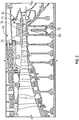
- an exemplary HPC 52 includes a plurality of cantilevered stators 76.
- the rotor disk 72 includes an abradable section 80 on a hub surface 78 from which extend a plurality of blades 74 located axially downstream of the cantilevered stators 76.
- the abradable section 80 operates as an interface for a plurality of vanes of the cantilevered stator 76.
- most, if not all, of the cantilevered stators 76 rub against the abradable section 80 to form an effective seal.
- the current coatings for cantilever stators include a plasma spray coating that is generally characterized by an accumulation of splats separated by intersplat boundaries parallel to the surface upon which the coating is disposed.
- a splat is formed when a droplet of the coating material impacts the surface that it is intended to protect. As one splat is formed atop another on the surface, intersplat boundaries are formed between successive splats.
- the current plasma spray coatings have a homogeneous distribution of larger pores throughout the coating along with the weak interfaces between respective splats, which results in a low to moderate ability to accommodate strain.
- strain capability of the coating is exceeded (either from thermal expansion, induced load from stator, or combination) the coating will delaminate by a "crack-jumping" mechanism whereby a crack occurs between pores and splat interfaces and propagates generally parallel to the substrate surface.
- the crack may propagate beyond the high strain zone due to the homogenous structure of the current coating and its lack of discreet separations perpendicular to the crack.
- a coating structure that alternatively provides a low modulus in a plane parallel to the substrate surface (not perpendicular like in the current coatings) while simultaneously being of a higher modulus in the other orientations (such as, for example, in a plane perpendicular to the substrate surface).
- This coating includes columns that are oriented perpendicular to the substrate and are separated from a neighboring column by either gaps or cracks. Level of separation and size of columns relate to the in-plane modulus (i.e., the modulus parallel to the plane of the substrate surface) which is generally low.
- This low modulus in a plane parallel the substrate surface means the coating will be more resilient to strain or from propagation of cracks formed due to the rub event with the stator.
- the disclosed columnar coating is more strain tolerant but is also more damage tolerant due to cracks having to jump from one column to the next.
- the coating is desirable for the coating to be a columnar coating with columns perpendicular to the substrate surface.
- This columnar coating can be produced by several processes. 1) Electron beam physical vapor deposition (EB-PVD) which builds columns of single crystals with defined gaps between columns. EB-PVD is expensive and utilizes a vacuum process and elevated temperature and is not conducive to coating large structures such as the hub surface 78 of rotor disk 72. 2) Vertically cracked air plasma spray coatings use a conventional air plasma spray method and material but with short standoff and higher coating temperatures to drive a quench crack vertically through the coating on cooling.
- EB-PVD Electron beam physical vapor deposition
- the coating produced by this method has a higher density (typically less than 10% porosity) than the other current art but has a lower modulus in a plane parallel to substrate surface.
- the high density of the coating and higher density columns may not be ideal for abradable applications due to a higher level of rub energy/heat generated during a rub event.
- SPS suspension plasma spray
- SPPS solution precursor plasma spray
- the current deposition mode understanding for SPS/SPPS is that fine particle motion in flight are directed by the plasma gas motion which means the particles will impinge on the substrate surface at angles less than normal (less than perpendicular to the substrate). This impingement angle drives a shadowing effect that forms columns from peaks in the surface and gaps/cracks that grow from the corresponding valleys. Due to the low momentum of the fine particles (because of their light weight), a liquid carrier provides the desirable additional momentum to get the fine particles into the plasma plume and projected toward the surface in the case of SPS. In SPPS, a liquid carrier provides the momentum to enter the plasma plume and also the medium to dissolve various ceramic chemical precursors.
- the liquid carrier breaks up on entering the plasma plume to yield a fine droplet size that then yields a fine ceramic projectile size that is directed by the plasma gas motion.
- SPS/SPPS is desirable over the other methods 1) and 2) because it is possible to use these techniques (SPS/SPPS) to generate a more defined gap/crack structure than the conventional air plasma sprayed vertically cracked structures that will yield lower rub energies generated by method 2).
- the columnar structures generated by SPS/SPPS have a lower in plane modulus which provides improved damage tolerance. The columnar structures and the columnar coatings are described in detail below.
- the abradable coating is applied onto a substrate such as the hub surface 78 to form the abradable section 80 via a thermal spray method or via a suspension plasma spray (SPS).
- a substrate such as the hub surface 78 to form the abradable section 80 via a thermal spray method or via a suspension plasma spray (SPS).
- SPS suspension plasma spray
- thermal spray methods melted (or heated) materials are sprayed onto a desired substrate.
- the "feedstock” (the suspension or solution) is heated by electrical (plasma or arc) or chemical means (combustion flame) and sprayed onto a surface.
- Thermal spray methods may include plasma spray, flame spray, high velocity oxygen fuel (HVOF), high velocity air fuel (HVAF), or a combination thereof.
- suspension plasma spray is a form of plasma spraying where the ceramic feedstock is dispersed in a liquid carrier to form a suspension before being injected into the plasma jet and deposited on a substrate.
- the plasma jet results in converting the ceramic particles into a stream of molten, semi-molten, or even solid particles that strike the surface of the substrate where the particles undergo rapid deformation and solidification to form the abradable coating.
- the method comprises providing a suspension comprising a carrier liquid with solid particles suspended therein, injecting the suspension into a plasma jet of a plasma spray device and directing the plasma jet toward a substrate to deposit a film formed from the particles onto the substrate.
- the spray parameters affect certain factors of the coating, such as the size and distribution of porosity, residual stresses, macro and microcracks, factors which have an important influence on the performance and eventual failure of the coating.
- the abradable coating formed on the substrate e.g., the hub surface 78
- the coating formed on the substrate has vertical gaps or cracks that enable the coating to better handle strain in a plane parallel to the coating surface (or in a plane parallel to the surface of the substrate).
- the vertical gaps or cracks are substantially perpendicular to the surface of the substrate upon which the coating is disposed.
- at least a portion of the gaps or cracks are perpendicular to a free surface of the coating (the free surface being the surface that contacts the atmosphere) or to the surface of the substrate.
- the cracks may be inclined at an angle of ⁇ 45 degrees or less to a perpendicular to the substrate, preferably be inclined at an angle of ⁇ 30 degrees or less to a perpendicular to the substrate, be inclined at an angle of ⁇ 25 degrees or less to a perpendicular to the substrate, be inclined at an angle of ⁇ 15 degrees or less to a perpendicular to the substrate, and more preferably be inclined at an angle of ⁇ 10 degrees or less to a perpendicular to the substrate.
- the coatings manufactured by the disclosed method have a porosity of 15 to 50 volume percent, preferably 25 to 48 volume percent, and more preferably 30 to 45 volume percent, based on total coating volume.
- the porosity may be determined by imaging the porous surface at a magnification of 250X using a scanning electron microscope and using image analysis to determine the porosity.
- Another method of measuring porosity includes mercury porosimetry. This method involves the intrusion of mercury at high pressure into a material through the use of a porosimeter. The pore size and volume can be determined based on the external pressure needed to force the mercury into a pore against the opposing force of the liquid's surface tension.
- the formation of the cracks or gaps in the coating results in the presence of a plurality of column-like structures situated adjacent to one another. These cracks or gaps permit the column-like structures to expand and contract during use (when subjected to strain or stress parallel to the surface of the coating or parallel to a surface of the substrate upon which the coating is disposed).
- the expansion and contraction of the column-like structures prevents spalling and provides the abradable coating with an extra measure of strain tolerance when compared with conventional coatings produces by air plasma processes.
- the column structure (with the voids and gaps located therebetween) prevents a strain from propagating from one column to adjacent columns across the coating.
- the global strain applied to the coating may exceed the local strain capabilities at a point in the coating because these local strains do not get transmitted across the coating. It is desirable for the columnar structure to provide compliance in the coating that in turn limits the in-plane stress in the coating that results from CTE mismatch and thermal gradients.
- the coating structure with the cracks and gaps provides the coating with extended life cycle characteristics and reduces the amount of maintenance that needs to be performed on the engine.
- the columns have an average width (measured parallel to the substrate surface) of 20 to 300 micrometers, preferably 50 to 150 micrometers, with a gap or crack average width of 1 to 30 micrometers, preferably 5 to 25 micrometers as measured 125 microns above the interface with the substrate (such as, for example, the hub surface 78).
- the gaps or cracks separate adjacent columns from one another.
- the gaps or cracks also provide the columns with a means to accommodate strain induced from the rub with the cantilever stator 76.
- the gaps or cracks can extend throughout the coating thickness. In another embodiment, the gaps or cracks do not extend throughout the coating thickness but extend from a free surface of the coating to a depth of greater than 25% of the coating thickness, preferably to a depth of greater than 50% of the coating thickness, and more preferably to a depth of greater than 75% of the coating thickness.
- the suspension comprises a carrier liquid with fine solid particles (e.g., the particles of the abradable material that eventually form the coating upon being disposed on a desired substrate).
- the carrier liquid is preferably one that can either suspend the particles permanently or at least for a short period of time during the spray process.
- the carrier liquid provides the mass to transfer the solid particles into the plasma plume.
- the carrier liquid evaporates upon contacting the flame leaving the particles to impact the substrate and form the abradable coating.
- Surfactants and dispersants that do not disrupt the structure of the abradable coating may optionally be used to suspend smaller particles (e.g., nanoparticles) in the liquid if desired.
- Waxes and polymers that are soluble in the liquid may also optionally be added to the liquid to serve as sacrificial pore formers in the coating if desired.
- the liquid used for the suspension may include polar solvents, non-polar solvents, or combinations thereof.
- the polar solvents may be aprotic solvent, protic solvents, or combinations thereof.
- Liquid aprotic polar solvents may include water, propylene carbonate, ethylene carbonate, butyrolactone, acetonitrile, benzonitrile, nitromethane, nitrobenzene, sulfolane, dimethylformamide, N-methylpyrrolidone, or the like, or a combination thereof.
- Polar protic solvents may include alcohols (e.g., methanol, ethanol, butanol, isopropanol, and the like), acetonitrile, nitromethane, or the like, or a combination thereof.
- Non-polar solvents such as benzene, toluene, methylene chloride, carbon tetrachloride, hexane, diethyl ether, tetrahydrofuran, or the like, or a combination thereof.
- Ionic liquids, including imidazolium salts, may also be used as the carrier liquid if desired.
- a preferred solvent for use in the suspension is water or an alcohol.
- a preferred alcohol is ethanol.
- the solvent may be used in amounts of 20 to 95, preferably 25 to 90, and more preferably 35 to 80 weight percent (wt%) based on the total weight of the suspension.
- the particles used in the suspension for coating cantilever substrates are typically the same chemistry as those used in tribological coatings or thermal barrier coatings in gas turbine engines that are subject to elevated operating temperatures.
- the particles used in the suspension include metal oxides including perovskites, zirconate or hafnate base ceramic compounds, zirconate or hafnate based ceramic compounds that have a cubic or tetragonal or tetragonal prime crystal structure, yttria stabilized zirconia (YSZ), cubic zirconia based ceramics such as, for example, gadolinia zirconia.
- Zr-Ta-Y ternary systems of the cubic, fluorite or orthorhombic crystal structure, or having a combination of the foregoing crystal structures may also be used. Details of some of these particles are provided below.
- the aforementioned metal oxides may be used either singly or in alloys with other metals or metals oxides.
- alumina may be used singly while the other metal oxides are used in alloy form.
- alumina and silicate based materials can also be used as particles in the suspension.
- the silicates may be based on the mono- and di-silicate systems, for example with ytterbia or yttria as the anion (e.g., YbSiO 5 , Yb 2 Si 2 O 7 , Y 2 SiO 5 , Y 2 Si 2 0 7 , or a combination thereof).
- ytterbia or yttria as the anion (e.g., YbSiO 5 , Yb 2 Si 2 O 7 , Y 2 SiO 5 , Y 2 Si 2 0 7 , or a combination thereof).
- Other materials such as Halfnon (HfSiO 4 ) may also be used.
- the alumina base material comprises mullite (Al 6 SiO 13 ).
- Perovskite materials may also be used and have the general structural formula ABO 3 , where A is Mg, Ca, Sr, Ba, or a combination thereof and B is Al, Mn, Si, Ti, Zr, Co, Ni, Sn, or a combination thereof.
- Rare earth perovskites may also be used as particulates in the suspension.
- perovskites examples include CaTiO 3 , MgTiO 3 , CaSiO 3 , CaSnO 3 , CaZrO 3 , MgZrO 3 , BaZrO 3 , SrZrO 3 , BaSnO 3 , CaSnO 3 , MgSnO 3 , SrTiO 3 , or the like, or a combination thereof.
- Partially or fully stabilized zirconia or hafnia may also be used as particles in the suspension.
- the stabilized zirconia may include yttria-, calcia-, magnesia-, ceria-, scandia, lanthanide series elements, hafnia- or alumina-stabilized zirconia or combinations thereof.
- Fully stabilized zirconia including 20YSZ (yttria-stabilized zirconia containing 20 wt% yttria) and Gd 2 Zr 2 O 7 may be used as particles in the suspension.
- Yttria stabilized zirconia comprising 4 to 9 mole percent of the yttria are preferred, with those having 7 to 9 mole percent more preferred, based on the total number of moles of the yttria stabilized zirconia.
- the solid particles generally have an average particle size that ranges from 50 nanometers to 10 micrometers, preferably 100 nanometers to 5 micrometer.
- the solid particles may be used in amounts of 5 to 80, preferably 10 to 75, and more preferably 20 to 65 wt%, based on the total weight of the suspension. In an exemplary embodiment, the solid particles may be used in amounts of 5 to 20 wt%, based on the total weight of the suspension.
- the particles may not be suspended in a carrier liquid but may co-exist as precursors with the carrier liquid as a solution.
- a particle precursor instead of injecting a powder suspended in a carrier liquid into the plasma plume, a particle precursor is used in conjunction with the carrier liquid to produce the abradable coating.
- This method is sometimes referred to as solution precursor plasma spray and includes injecting a particle precursor solution (hereinafter precursor solution) into the plume of a plasma flame, evaporating solvent from the precursor solution droplets, and pyrolyzing the resulting solid to form the abradable coating. Particles formed during the travel of the solution through the plume impinge on the substrate.
- Exemplary precursors include a variety of aluminum and zirconium salts, as long as the counterions therein thermally decompose during the 700-800°C processing step in a way that does not interfere with the formation of alumina-zirconia.
- Suitable aluminum salts include aluminum nitrate, aluminum acetate, aluminum chloride, aluminum isopropoxide, aluminum carbonate, aluminum citrate, hydrates of the foregoing salts, and mixtures thereof.
- the aluminum salt comprises aluminum nitrate or a hydrate thereof.
- Suitable zirconium salts include zirconium nitrate, zirconium acetate, zirconium chloride, zirconium isopropoxide, zirconium carbonate, zirconium citrate, hydrates of the foregoing salts, and mixtures thereof.
- the zirconium salt comprises zirconium acetate or a hydrate thereof.
- the aluminum salt comprises aluminum nitrate or a hydrate thereof, and the zirconium salt comprises zirconium acetate or a hydrate thereof.
- the aqueous solution can comprise the dissolved aluminum salt and the dissolved zirconium salt in amounts sufficient to provide a molar ratio of aluminum to zirconium of about 2.4:1 to about 5.6:1, specifically about 3.0:1 to about 4.6:1.
- the aqueous solution can contain less than 2 weight percent, specifically less than 1 weight percent, of components other than water, the dissolved aluminum salt, and the dissolved zirconium salt.
- the aqueous solution consists of water, the dissolved aluminum salt, and the dissolved zirconium salt.
- a preferred solvent for use in the solution is water or an alcohol.
- a preferred alcohol is ethanol.
- the solvent may be used in amounts of 20 to 95, preferably 25 to 90, and more preferably 35 to 80 weight percent (wt%) based on the total weight of the solution.
- a suspension may contain particles as well as a particle precursor in a carrier liquid.
- the carrier liquid contains particles as well as particle precursors.
- the carrier liquid is mixed with the solid particles or with the salt precursor in the desired quantity to form the suspension or solution respectively.
- the suspension or solution is then injected into the plume of a plasma flame at a pressure of 20 to 100 pounds per square inch (psi), preferably 22 to 50 psi and more preferably 30 to 40 psi.
- psi pounds per square inch
- the interaction of the suspension or solution with the plasma plume atomizes the carrier liquid to form small individual liquid droplets (with solid particles contained therein).
- the coating is generally applied to the substrate under atmospheric pressure conditions, but can be applied at pressures below atmospheric if so desired.
- the substrate may have a bond coat applied thereto prior to the deposition of the abradable coating.
- the substrate temperature during the formation of a typical coating is 300°C to 1100°C, with a preferred range of 400°C to 900°C.
- the method disclosed herein may be used to form a gradient coating on the substrate (e.g., the cantilever stator).
- Gradient coatings may be formed by creating two different feedstocks (e.g., a first feedstock and a second feedstock) having different compositions and by simultaneously or successively varying the feed of the respective feed stocks to the plasma flame. For example, the amount of the first feedstock to the plasma flame can be increased, while at the same time, the amount of the second feedstock to the plasma flame can be reduced.
- the abradable coating can also be layered with one or more base layers and one or more top layers.
- the base layer may include a high toughness material such as YSZ that is provided at the abradable/metallic substrate interface to address maximum strain levels due to thermal expansion mismatch at the abradable/metallic substrate interface.
- the first abradable layer is primarily utilized to provide high fracture toughness at the ceramic/metal interface where CTE mismatch is greatest and a high toughness material (yttria stabilized zirconia) is desired.
- the base layers adjacent to the substrate may be of a single material composition, for example, YSZ or gadolinia zirconate, a multi-material layered composition, for, example, alternating layers of YSZ and gadolinia zirconate, or a mixed material, for example, via the co-deposition of YSZ and gadolinia zirconate.
- the abradable coating has a thickness of 5 mils to 50 mils (125 ⁇ m to 1250 ⁇ m), preferably 15 mils to 30 mils (375 ⁇ m to 750 ⁇ m).
- FIG. 3 depicts a photomicrograph of a YSZ coating with vertical cracks in the coating. These vertical cracks are substantially perpendicular to the substrate surface.
- the coating has an average adhesive tensile strength of greater than 2000 pounds per square inch (psi), preferably greater than 4000 psi, preferably greater than 6000 psi, and more preferably greater than 8000 psi; when measured as per ASTM C633.
- the abradable coating may be a multilayered coating.
- the multilayered coating may comprise a first abradable coating upon which is disposed a second abradable coating.
- the first abradable coating and the second abradable coating may be in direct contact with each other with the first abradable coating also contacting the substrate.
- the second abradable coating may have a different composition from that of the first abradable coating.
- the abradable coating can have multiple layers where each layer can have a different composition.
- each separate layer may have a gradient in composition.
- the first abradable coating is primarily utilized to provide high fracture toughness at the ceramic/metal interface where the coefficient of thermal expansion (CTE) mismatch is greatest.
- the first abradable coating may therefore be a high toughness material such as yttria stabilized zirconia.
- the complex oxides listed above are primarily intended for the second abradable coating.
- the coating is advantageous in that the vertical cracks and gaps present in the coating provide the coating with a strain tolerance that is significantly greater than that produced in conventional air plasma sprays. As noted above, this provides a longer life cycle for the engine part as well as lower maintenance costs.
Landscapes
- Chemical & Material Sciences (AREA)
- Engineering & Computer Science (AREA)
- Mechanical Engineering (AREA)
- Materials Engineering (AREA)
- Plasma & Fusion (AREA)
- Physics & Mathematics (AREA)
- Chemical Kinetics & Catalysis (AREA)
- Metallurgy (AREA)
- Organic Chemistry (AREA)
- General Engineering & Computer Science (AREA)
- Ceramic Engineering (AREA)
- Inorganic Chemistry (AREA)
- Coating By Spraying Or Casting (AREA)
- Turbine Rotor Nozzle Sealing (AREA)
Applications Claiming Priority (1)
| Application Number | Priority Date | Filing Date | Title |
|---|---|---|---|
| US15/656,960 US10822951B2 (en) | 2017-07-21 | 2017-07-21 | Suspension plasma spray abradable coating for cantilever stator |
Publications (3)
| Publication Number | Publication Date |
|---|---|
| EP3431631A1 true EP3431631A1 (de) | 2019-01-23 |
| EP3431631B1 EP3431631B1 (de) | 2020-12-23 |
| EP3431631B8 EP3431631B8 (de) | 2021-04-14 |
Family
ID=63035944
Family Applications (1)
| Application Number | Title | Priority Date | Filing Date |
|---|---|---|---|
| EP18185030.6A Active EP3431631B8 (de) | 2017-07-21 | 2018-07-23 | Abreibbare suspensionsplasmaspritzschicht für einen freitragenden stator |
Country Status (2)
| Country | Link |
|---|---|
| US (2) | US10822951B2 (de) |
| EP (1) | EP3431631B8 (de) |
Cited By (4)
| Publication number | Priority date | Publication date | Assignee | Title |
|---|---|---|---|---|
| WO2022015388A2 (en) | 2020-04-27 | 2022-01-20 | Raytheon Technologies Corporation | Thermal barrier coating |
| CN115287574A (zh) * | 2022-08-25 | 2022-11-04 | 航天特种材料及工艺技术研究所 | 一种高韧性抗烧蚀涂层及其制备方法 |
| US20230295789A1 (en) * | 2022-03-15 | 2023-09-21 | Applied Materials, Inc. | Dense vertically segmented silicon coating for low defectivity in high-temperature rapid thermal processing |
| EP4253593A1 (de) * | 2022-04-01 | 2023-10-04 | Raytheon Technologies Corporation | Säulenwachstumssteuerungsverfahren für suspensionsplasmaspray und daraus hergestellte artikel |
Families Citing this family (5)
| Publication number | Priority date | Publication date | Assignee | Title |
|---|---|---|---|---|
| EP3712379A1 (de) * | 2019-03-22 | 2020-09-23 | Siemens Aktiengesellschaft | Vollstabilisiertes zirconiumdioxid in einem dichtungssystem |
| CN110042371B (zh) * | 2019-05-24 | 2023-10-20 | 北京化工大学 | 一种采用低温等离子体制备多孔性热障涂层的装置及方法 |
| CN117512495B (zh) * | 2023-11-03 | 2025-12-05 | 内蒙古工业大学 | 一种钙钛矿结构复合涂层及其制备方法和应用 |
| US12503953B2 (en) * | 2024-02-13 | 2025-12-23 | Rtx Corporation | Ceramic matrix composite component with coating |
| CN120271340B (zh) * | 2025-03-28 | 2025-12-05 | 太仓宏达俊盟新材料有限公司 | 一种超细氧化锆纳米复合粉体及其研磨制备方法 |
Citations (2)
| Publication number | Priority date | Publication date | Assignee | Title |
|---|---|---|---|---|
| US20150044444A1 (en) * | 2012-04-23 | 2015-02-12 | The University Of Connecticut | Method of forming thermal barrier coating, thermal barrier coating formed thereby, and article comprising same |
| US20170152753A1 (en) * | 2015-12-01 | 2017-06-01 | United Technologies Corporation | Thermal Barrier Coatings and Methods |
Family Cites Families (5)
| Publication number | Priority date | Publication date | Assignee | Title |
|---|---|---|---|---|
| US6503575B1 (en) * | 2000-05-22 | 2003-01-07 | Praxair S.T. Technology, Inc. | Process for producing graded coated articles |
| US7563503B2 (en) * | 2003-01-10 | 2009-07-21 | The University Of Connecticut | Coatings, materials, articles, and methods of making thereof |
| DE102008007870A1 (de) * | 2008-02-06 | 2009-08-13 | Forschungszentrum Jülich GmbH | Wärmedämmschichtsystem sowie Verfahren zu seiner Herstellung |
| US8206101B2 (en) * | 2008-06-16 | 2012-06-26 | General Electric Company | Windward cooled turbine nozzle |
| US20130071235A1 (en) * | 2011-09-20 | 2013-03-21 | Christopher W. Strock | Light weight abradable air seal |
-
2017
- 2017-07-21 US US15/656,960 patent/US10822951B2/en active Active
-
2018
- 2018-07-23 EP EP18185030.6A patent/EP3431631B8/de active Active
-
2020
- 2020-10-22 US US17/077,459 patent/US20210040854A1/en active Pending
Patent Citations (2)
| Publication number | Priority date | Publication date | Assignee | Title |
|---|---|---|---|---|
| US20150044444A1 (en) * | 2012-04-23 | 2015-02-12 | The University Of Connecticut | Method of forming thermal barrier coating, thermal barrier coating formed thereby, and article comprising same |
| US20170152753A1 (en) * | 2015-12-01 | 2017-06-01 | United Technologies Corporation | Thermal Barrier Coatings and Methods |
Non-Patent Citations (1)
| Title |
|---|
| MAURICE GELL ET AL: "Thermal Barrier Coatings Made by the Solution Precursor Plasma Spray Process", JOURNAL OF THERMAL SPRAY TECHNOLOGY, vol. 17, no. 1, 28 December 2007 (2007-12-28), pages 124 - 135, XP055019277, ISSN: 1059-9630, DOI: 10.1007/s11666-007-9141-5 * |
Cited By (6)
| Publication number | Priority date | Publication date | Assignee | Title |
|---|---|---|---|---|
| WO2022015388A2 (en) | 2020-04-27 | 2022-01-20 | Raytheon Technologies Corporation | Thermal barrier coating |
| EP4143365A4 (de) * | 2020-04-27 | 2024-05-29 | RTX Corporation | Wärmedämmschicht |
| US20230295789A1 (en) * | 2022-03-15 | 2023-09-21 | Applied Materials, Inc. | Dense vertically segmented silicon coating for low defectivity in high-temperature rapid thermal processing |
| EP4253593A1 (de) * | 2022-04-01 | 2023-10-04 | Raytheon Technologies Corporation | Säulenwachstumssteuerungsverfahren für suspensionsplasmaspray und daraus hergestellte artikel |
| CN115287574A (zh) * | 2022-08-25 | 2022-11-04 | 航天特种材料及工艺技术研究所 | 一种高韧性抗烧蚀涂层及其制备方法 |
| CN115287574B (zh) * | 2022-08-25 | 2023-06-16 | 航天特种材料及工艺技术研究所 | 一种高韧性抗烧蚀涂层及其制备方法 |
Also Published As
| Publication number | Publication date |
|---|---|
| US10822951B2 (en) | 2020-11-03 |
| EP3431631B1 (de) | 2020-12-23 |
| US20190024510A1 (en) | 2019-01-24 |
| EP3431631B8 (de) | 2021-04-14 |
| US20210040854A1 (en) | 2021-02-11 |
Similar Documents
| Publication | Publication Date | Title |
|---|---|---|
| EP3431631B1 (de) | Abreibbare suspensionsplasmaspritzschicht für einen freitragenden stator | |
| JP7271429B2 (ja) | セラミック化合物を含む層を有する固体基材の表面をコーティングする方法、及び該方法で得られたコーティング基材 | |
| Łatka | Thermal barrier coatings manufactured by suspension plasma spraying-a review | |
| US7361386B2 (en) | Functional coatings for the reduction of oxygen permeation and stress and method of forming the same | |
| US9017792B2 (en) | Tri-barrier ceramic coating | |
| CN101454477B (zh) | 钨青铜结构材料的应用以及具有热障涂层的涡轮部件 | |
| US20150147527A1 (en) | Thermal barrier coating and article comprising same | |
| US7537806B2 (en) | Method for producing a thermal barrier coating on a substrate | |
| WO2007116547A1 (ja) | 遮熱コーティング部材及びその製造方法ならびに遮熱コート材料、ガスタービン及び焼結体 | |
| US11624288B2 (en) | Slotted ceramic coating with a reactive phase coating disposed thereon for improved CMAS resistance and methods of forming the same | |
| US9139477B2 (en) | Ceramic powders and methods therefor | |
| US10364701B2 (en) | CMAS barrier coating for a gas turbine engine having a reactive material that reacts with a layer of environmental contaminant compositions and method of applying the same | |
| US20160010471A1 (en) | Coating systems and methods therefor | |
| EP4242343A1 (de) | Cmas-beständige wärmedämmschicht für flugzeugmotorteile | |
| Di Girolamo et al. | Microstructure and thermal properties of plasma-sprayed ceramic thermal barrier coatings | |
| JP2009280854A (ja) | セラミックス膜とその製造方法、及び遮熱コーティング構造 | |
| Li et al. | Thermal barrier coating for aerial and aerospace engine | |
| US20230313409A1 (en) | Suspension plasma spray columnar growth control methods and articles manufactured therefrom | |
| Trice et al. | Thermal barrier coatings | |
| Naga et al. | Combined zirconia toughened alumina (ZTA) stacks obtained by electron beam physical vapour deposition | |
| CA3040347C (en) | Method for coating a surface of a solid substrate with a layer comprising a ceramic compound, and coated substrate thus obtained | |
| Di Girolamo et al. | Thermally sprayed coatings for high-temperature applications | |
| Viswanathan | An Integrated Assessment of Processing, Microstructure, Properties and Performance in Plasma Sprayed Thermal Barrier Coatings | |
| Guo et al. | Thermal and Mechanical Properties of Novel Lanthanum Zirconate Based Thermal Barrier Coatings | |
| Feuerstein et al. | Praxair Surface Technologies, Inc. Indianapolis, Indiana, USA |
Legal Events
| Date | Code | Title | Description |
|---|---|---|---|
| PUAI | Public reference made under article 153(3) epc to a published international application that has entered the european phase |
Free format text: ORIGINAL CODE: 0009012 |
|
| STAA | Information on the status of an ep patent application or granted ep patent |
Free format text: STATUS: THE APPLICATION HAS BEEN PUBLISHED |
|
| AK | Designated contracting states |
Kind code of ref document: A1 Designated state(s): AL AT BE BG CH CY CZ DE DK EE ES FI FR GB GR HR HU IE IS IT LI LT LU LV MC MK MT NL NO PL PT RO RS SE SI SK SM TR |
|
| AX | Request for extension of the european patent |
Extension state: BA ME |
|
| STAA | Information on the status of an ep patent application or granted ep patent |
Free format text: STATUS: REQUEST FOR EXAMINATION WAS MADE |
|
| 17P | Request for examination filed |
Effective date: 20190723 |
|
| RBV | Designated contracting states (corrected) |
Designated state(s): AL AT BE BG CH CY CZ DE DK EE ES FI FR GB GR HR HU IE IS IT LI LT LU LV MC MK MT NL NO PL PT RO RS SE SI SK SM TR |
|
| STAA | Information on the status of an ep patent application or granted ep patent |
Free format text: STATUS: EXAMINATION IS IN PROGRESS |
|
| 17Q | First examination report despatched |
Effective date: 20191002 |
|
| GRAP | Despatch of communication of intention to grant a patent |
Free format text: ORIGINAL CODE: EPIDOSNIGR1 |
|
| STAA | Information on the status of an ep patent application or granted ep patent |
Free format text: STATUS: GRANT OF PATENT IS INTENDED |
|
| INTG | Intention to grant announced |
Effective date: 20200706 |
|
| GRAS | Grant fee paid |
Free format text: ORIGINAL CODE: EPIDOSNIGR3 |
|
| GRAA | (expected) grant |
Free format text: ORIGINAL CODE: 0009210 |
|
| STAA | Information on the status of an ep patent application or granted ep patent |
Free format text: STATUS: THE PATENT HAS BEEN GRANTED |
|
| AK | Designated contracting states |
Kind code of ref document: B1 Designated state(s): AL AT BE BG CH CY CZ DE DK EE ES FI FR GB GR HR HU IE IS IT LI LT LU LV MC MK MT NL NO PL PT RO RS SE SI SK SM TR |
|
| REG | Reference to a national code |
Ref country code: GB Ref legal event code: FG4D |
|
| REG | Reference to a national code |
Ref country code: DE Ref legal event code: R096 Ref document number: 602018011018 Country of ref document: DE |
|
| REG | Reference to a national code |
Ref country code: AT Ref legal event code: REF Ref document number: 1347811 Country of ref document: AT Kind code of ref document: T Effective date: 20210115 |
|
| REG | Reference to a national code |
Ref country code: IE Ref legal event code: FG4D |
|
| REG | Reference to a national code |
Ref country code: DE Ref legal event code: R081 Ref document number: 602018011018 Country of ref document: DE Owner name: RAYTHEON TECHNOLOGIES CORPORATION, FARMINGTON, US Free format text: FORMER OWNER: UNITED TECHNOLOGIES CORP., FARMINGTON, CONN., US Ref country code: DE Ref legal event code: R081 Ref document number: 602018011018 Country of ref document: DE Owner name: RTX CORPORATION (N.D.GES.D. STAATES DELAWARE),, US Free format text: FORMER OWNER: UNITED TECHNOLOGIES CORP., FARMINGTON, CONN., US |
|
| RAP2 | Party data changed (patent owner data changed or rights of a patent transferred) |
Owner name: RAYTHEON TECHNOLOGIES CORPORATION |
|
| REG | Reference to a national code |
Ref country code: CH Ref legal event code: PK Free format text: BERICHTIGUNG B8 |
|
| PG25 | Lapsed in a contracting state [announced via postgrant information from national office to epo] |
Ref country code: RS Free format text: LAPSE BECAUSE OF FAILURE TO SUBMIT A TRANSLATION OF THE DESCRIPTION OR TO PAY THE FEE WITHIN THE PRESCRIBED TIME-LIMIT Effective date: 20201223 Ref country code: FI Free format text: LAPSE BECAUSE OF FAILURE TO SUBMIT A TRANSLATION OF THE DESCRIPTION OR TO PAY THE FEE WITHIN THE PRESCRIBED TIME-LIMIT Effective date: 20201223 Ref country code: GR Free format text: LAPSE BECAUSE OF FAILURE TO SUBMIT A TRANSLATION OF THE DESCRIPTION OR TO PAY THE FEE WITHIN THE PRESCRIBED TIME-LIMIT Effective date: 20210324 Ref country code: NO Free format text: LAPSE BECAUSE OF FAILURE TO SUBMIT A TRANSLATION OF THE DESCRIPTION OR TO PAY THE FEE WITHIN THE PRESCRIBED TIME-LIMIT Effective date: 20210323 |
|
| REG | Reference to a national code |
Ref country code: AT Ref legal event code: MK05 Ref document number: 1347811 Country of ref document: AT Kind code of ref document: T Effective date: 20201223 |
|
| REG | Reference to a national code |
Ref country code: NL Ref legal event code: MP Effective date: 20201223 |
|
| PG25 | Lapsed in a contracting state [announced via postgrant information from national office to epo] |
Ref country code: BG Free format text: LAPSE BECAUSE OF FAILURE TO SUBMIT A TRANSLATION OF THE DESCRIPTION OR TO PAY THE FEE WITHIN THE PRESCRIBED TIME-LIMIT Effective date: 20210323 Ref country code: LV Free format text: LAPSE BECAUSE OF FAILURE TO SUBMIT A TRANSLATION OF THE DESCRIPTION OR TO PAY THE FEE WITHIN THE PRESCRIBED TIME-LIMIT Effective date: 20201223 Ref country code: SE Free format text: LAPSE BECAUSE OF FAILURE TO SUBMIT A TRANSLATION OF THE DESCRIPTION OR TO PAY THE FEE WITHIN THE PRESCRIBED TIME-LIMIT Effective date: 20201223 |
|
| PG25 | Lapsed in a contracting state [announced via postgrant information from national office to epo] |
Ref country code: NL Free format text: LAPSE BECAUSE OF FAILURE TO SUBMIT A TRANSLATION OF THE DESCRIPTION OR TO PAY THE FEE WITHIN THE PRESCRIBED TIME-LIMIT Effective date: 20201223 Ref country code: HR Free format text: LAPSE BECAUSE OF FAILURE TO SUBMIT A TRANSLATION OF THE DESCRIPTION OR TO PAY THE FEE WITHIN THE PRESCRIBED TIME-LIMIT Effective date: 20201223 |
|
| REG | Reference to a national code |
Ref country code: LT Ref legal event code: MG9D |
|
| PG25 | Lapsed in a contracting state [announced via postgrant information from national office to epo] |
Ref country code: SM Free format text: LAPSE BECAUSE OF FAILURE TO SUBMIT A TRANSLATION OF THE DESCRIPTION OR TO PAY THE FEE WITHIN THE PRESCRIBED TIME-LIMIT Effective date: 20201223 Ref country code: EE Free format text: LAPSE BECAUSE OF FAILURE TO SUBMIT A TRANSLATION OF THE DESCRIPTION OR TO PAY THE FEE WITHIN THE PRESCRIBED TIME-LIMIT Effective date: 20201223 Ref country code: SK Free format text: LAPSE BECAUSE OF FAILURE TO SUBMIT A TRANSLATION OF THE DESCRIPTION OR TO PAY THE FEE WITHIN THE PRESCRIBED TIME-LIMIT Effective date: 20201223 Ref country code: RO Free format text: LAPSE BECAUSE OF FAILURE TO SUBMIT A TRANSLATION OF THE DESCRIPTION OR TO PAY THE FEE WITHIN THE PRESCRIBED TIME-LIMIT Effective date: 20201223 Ref country code: PT Free format text: LAPSE BECAUSE OF FAILURE TO SUBMIT A TRANSLATION OF THE DESCRIPTION OR TO PAY THE FEE WITHIN THE PRESCRIBED TIME-LIMIT Effective date: 20210423 Ref country code: LT Free format text: LAPSE BECAUSE OF FAILURE TO SUBMIT A TRANSLATION OF THE DESCRIPTION OR TO PAY THE FEE WITHIN THE PRESCRIBED TIME-LIMIT Effective date: 20201223 |
|
| PG25 | Lapsed in a contracting state [announced via postgrant information from national office to epo] |
Ref country code: AT Free format text: LAPSE BECAUSE OF FAILURE TO SUBMIT A TRANSLATION OF THE DESCRIPTION OR TO PAY THE FEE WITHIN THE PRESCRIBED TIME-LIMIT Effective date: 20201223 Ref country code: PL Free format text: LAPSE BECAUSE OF FAILURE TO SUBMIT A TRANSLATION OF THE DESCRIPTION OR TO PAY THE FEE WITHIN THE PRESCRIBED TIME-LIMIT Effective date: 20201223 |
|
| REG | Reference to a national code |
Ref country code: DE Ref legal event code: R097 Ref document number: 602018011018 Country of ref document: DE |
|
| PG25 | Lapsed in a contracting state [announced via postgrant information from national office to epo] |
Ref country code: IS Free format text: LAPSE BECAUSE OF FAILURE TO SUBMIT A TRANSLATION OF THE DESCRIPTION OR TO PAY THE FEE WITHIN THE PRESCRIBED TIME-LIMIT Effective date: 20210423 |
|
| PG25 | Lapsed in a contracting state [announced via postgrant information from national office to epo] |
Ref country code: AL Free format text: LAPSE BECAUSE OF FAILURE TO SUBMIT A TRANSLATION OF THE DESCRIPTION OR TO PAY THE FEE WITHIN THE PRESCRIBED TIME-LIMIT Effective date: 20201223 Ref country code: CZ Free format text: LAPSE BECAUSE OF FAILURE TO SUBMIT A TRANSLATION OF THE DESCRIPTION OR TO PAY THE FEE WITHIN THE PRESCRIBED TIME-LIMIT Effective date: 20201223 Ref country code: IT Free format text: LAPSE BECAUSE OF FAILURE TO SUBMIT A TRANSLATION OF THE DESCRIPTION OR TO PAY THE FEE WITHIN THE PRESCRIBED TIME-LIMIT Effective date: 20201223 |
|
| PLBE | No opposition filed within time limit |
Free format text: ORIGINAL CODE: 0009261 |
|
| STAA | Information on the status of an ep patent application or granted ep patent |
Free format text: STATUS: NO OPPOSITION FILED WITHIN TIME LIMIT |
|
| PG25 | Lapsed in a contracting state [announced via postgrant information from national office to epo] |
Ref country code: DK Free format text: LAPSE BECAUSE OF FAILURE TO SUBMIT A TRANSLATION OF THE DESCRIPTION OR TO PAY THE FEE WITHIN THE PRESCRIBED TIME-LIMIT Effective date: 20201223 |
|
| 26N | No opposition filed |
Effective date: 20210924 |
|
| PG25 | Lapsed in a contracting state [announced via postgrant information from national office to epo] |
Ref country code: ES Free format text: LAPSE BECAUSE OF FAILURE TO SUBMIT A TRANSLATION OF THE DESCRIPTION OR TO PAY THE FEE WITHIN THE PRESCRIBED TIME-LIMIT Effective date: 20201223 |
|
| PG25 | Lapsed in a contracting state [announced via postgrant information from national office to epo] |
Ref country code: SI Free format text: LAPSE BECAUSE OF FAILURE TO SUBMIT A TRANSLATION OF THE DESCRIPTION OR TO PAY THE FEE WITHIN THE PRESCRIBED TIME-LIMIT Effective date: 20201223 |
|
| REG | Reference to a national code |
Ref country code: CH Ref legal event code: PL |
|
| PG25 | Lapsed in a contracting state [announced via postgrant information from national office to epo] |
Ref country code: MC Free format text: LAPSE BECAUSE OF FAILURE TO SUBMIT A TRANSLATION OF THE DESCRIPTION OR TO PAY THE FEE WITHIN THE PRESCRIBED TIME-LIMIT Effective date: 20201223 |
|
| REG | Reference to a national code |
Ref country code: BE Ref legal event code: MM Effective date: 20210731 |
|
| PG25 | Lapsed in a contracting state [announced via postgrant information from national office to epo] |
Ref country code: LI Free format text: LAPSE BECAUSE OF NON-PAYMENT OF DUE FEES Effective date: 20210731 Ref country code: CH Free format text: LAPSE BECAUSE OF NON-PAYMENT OF DUE FEES Effective date: 20210731 |
|
| PG25 | Lapsed in a contracting state [announced via postgrant information from national office to epo] |
Ref country code: IS Free format text: LAPSE BECAUSE OF FAILURE TO SUBMIT A TRANSLATION OF THE DESCRIPTION OR TO PAY THE FEE WITHIN THE PRESCRIBED TIME-LIMIT Effective date: 20210423 Ref country code: LU Free format text: LAPSE BECAUSE OF NON-PAYMENT OF DUE FEES Effective date: 20210723 |
|
| PG25 | Lapsed in a contracting state [announced via postgrant information from national office to epo] |
Ref country code: IE Free format text: LAPSE BECAUSE OF NON-PAYMENT OF DUE FEES Effective date: 20210723 Ref country code: BE Free format text: LAPSE BECAUSE OF NON-PAYMENT OF DUE FEES Effective date: 20210731 |
|
| P01 | Opt-out of the competence of the unified patent court (upc) registered |
Effective date: 20230521 |
|
| PG25 | Lapsed in a contracting state [announced via postgrant information from national office to epo] |
Ref country code: CY Free format text: LAPSE BECAUSE OF FAILURE TO SUBMIT A TRANSLATION OF THE DESCRIPTION OR TO PAY THE FEE WITHIN THE PRESCRIBED TIME-LIMIT Effective date: 20201223 |
|
| PG25 | Lapsed in a contracting state [announced via postgrant information from national office to epo] |
Ref country code: HU Free format text: LAPSE BECAUSE OF FAILURE TO SUBMIT A TRANSLATION OF THE DESCRIPTION OR TO PAY THE FEE WITHIN THE PRESCRIBED TIME-LIMIT; INVALID AB INITIO Effective date: 20180723 |
|
| PG25 | Lapsed in a contracting state [announced via postgrant information from national office to epo] |
Ref country code: MK Free format text: LAPSE BECAUSE OF FAILURE TO SUBMIT A TRANSLATION OF THE DESCRIPTION OR TO PAY THE FEE WITHIN THE PRESCRIBED TIME-LIMIT Effective date: 20201223 |
|
| PG25 | Lapsed in a contracting state [announced via postgrant information from national office to epo] |
Ref country code: MT Free format text: LAPSE BECAUSE OF FAILURE TO SUBMIT A TRANSLATION OF THE DESCRIPTION OR TO PAY THE FEE WITHIN THE PRESCRIBED TIME-LIMIT Effective date: 20201223 |
|
| PGFP | Annual fee paid to national office [announced via postgrant information from national office to epo] |
Ref country code: GB Payment date: 20250619 Year of fee payment: 8 |
|
| PGFP | Annual fee paid to national office [announced via postgrant information from national office to epo] |
Ref country code: FR Payment date: 20250620 Year of fee payment: 8 |
|
| REG | Reference to a national code |
Ref country code: DE Ref legal event code: R081 Ref document number: 602018011018 Country of ref document: DE Owner name: RTX CORPORATION (N.D.GES.D. STAATES DELAWARE),, US Free format text: FORMER OWNER: RAYTHEON TECHNOLOGIES CORPORATION, FARMINGTON, CT, US |
|
| PGFP | Annual fee paid to national office [announced via postgrant information from national office to epo] |
Ref country code: DE Payment date: 20250620 Year of fee payment: 8 |
|
| PG25 | Lapsed in a contracting state [announced via postgrant information from national office to epo] |
Ref country code: TR Free format text: LAPSE BECAUSE OF FAILURE TO SUBMIT A TRANSLATION OF THE DESCRIPTION OR TO PAY THE FEE WITHIN THE PRESCRIBED TIME-LIMIT Effective date: 20201223 |