EP3431768B1 - Pompe de refroidissement réglable - Google Patents
Pompe de refroidissement réglable Download PDFInfo
- Publication number
- EP3431768B1 EP3431768B1 EP18382529.8A EP18382529A EP3431768B1 EP 3431768 B1 EP3431768 B1 EP 3431768B1 EP 18382529 A EP18382529 A EP 18382529A EP 3431768 B1 EP3431768 B1 EP 3431768B1
- Authority
- EP
- European Patent Office
- Prior art keywords
- shutter
- coolant pump
- housing
- impeller
- adjustable
- Prior art date
- Legal status (The legal status is an assumption and is not a legal conclusion. Google has not performed a legal analysis and makes no representation as to the accuracy of the status listed.)
- Not-in-force
Links
Images




Classifications
-
- F—MECHANICAL ENGINEERING; LIGHTING; HEATING; WEAPONS; BLASTING
- F04—POSITIVE - DISPLACEMENT MACHINES FOR LIQUIDS; PUMPS FOR LIQUIDS OR ELASTIC FLUIDS
- F04D—NON-POSITIVE-DISPLACEMENT PUMPS
- F04D15/00—Control, e.g. regulation, of pumps, pumping installations or systems
- F04D15/0027—Varying behaviour or the very pump
- F04D15/0038—Varying behaviour or the very pump by varying the effective cross-sectional area of flow through the rotor
Definitions
- the present disclosure relates to coolant pumps, particularly adjustable coolant pumps.
- the present disclosure further relates to methods of operation of adjustable coolant pumps.
- the aforementioned application presents a controllable coolant pump where the adjustment element is mechanically activated by means of a vacuum. This negative pressure is applied to an annular membrane which is deformed due to the pressure gradient respect to the atmospheric pressure at the other side of the annular membrane.
- the membrane pushes a support element connected, through several rods, to the adjustment element, covering the output of the impeller of the pump, which never stops spinning. Therefore the hydraulic resistance of the circuit is increased due to the adjustment element, and this is reflected in a reduction of the flow rate.
- the flexible material of the membranes may be prone to suffer from wear which may cause inaccuracy of the function of regulation of the shutter and even a failure of the membrane.
- some examples of pumps comprise a plate positioned between the impeller and the shutter or adjustment element to avoid the risk of interference.
- this plate generates a bulky and complex configuration of the adjustable coolant pump.
- static sealing systems which are solutions where sealing is only achieved at the end of the stroke, allow the fluid migration between zones at different pressures during the shutter displacement in axial direction, resulting in a slower and more inefficient activation of the system and in a reduction of the adjustment capability during the activation.
- an adjustable coolant pump is provided according to claim 1.
- the end-stop element may provide a perfectly defined and fixed end-stop position for the adjustment element or shutter, when covering, at least partially the impeller.
- an adjustable coolant pump comprising the end-stop element may avoid any possible contact of the shutter and the impeller, for instance, when the impeller may spin and at least a portion of the outflow region may be covered.
- the adjustable coolant pump according to this aspect may absorb at the same time the clearances and tolerances of the manufacturing and assembly of the components in such a way that a regulation function may not be affected.
- the adjustable coolant pump according to this aspect does not comprise any plate between the impeller and the shutter, so a simple, compact and reliable configuration may be achieved.
- the housing may further comprise an annular wall extending from the bottom face in axial direction in such a way that a cavity to receive the shutter may be defined at least by the annular wall and the bottom face; wherein the adjustable coolant pump may further comprise an adjustment sealing arrangement provided between the shutter and the annular wall, the sealing arrangement comprising a ring seal attached either to the shutter or the annular wall, in such a way that a dynamic sealing between the shutter and the housing is defined. Thanks to the adjustment sealing arrangement, a gap between the annular wall of the housing and the shutter may be eliminated. Thus, a backflow of the coolant between the shutter and the housing is avoided or at least reduced, even when the shutter is displaced along the axis of rotation. Therefore, the adjustment capability of the shutter is not reduced.
- the adjustment sealing arrangement may provide a dynamic sealing between the shutter and the housing along the stroke of the shutter.
- the sealing may be achieved in the annular wall which may be substantially parallel to the direction of a relative motion between the annular wall and the shutter.
- a sealing function of the adjustment sealing arrangement may be independent of the aforementioned clearances and tolerances of the manufacturing and assembly of the components. Therefore, the sealing function of the adjustment sealing arrangement may be achieved and maintained regardless of the clearances and tolerances between the shutter and the housing.
- the sealing function of the adjustment sealing arrangement is present regardless of the relative position between the shutter and the housing.
- the sealing function is also achieved in the end points of the stroke of the shutter.
- the adjustable coolant pump may further comprise an annular piston displaceable in axial direction, an annular groove inside of which the annular piston is displaceable, wherein the annular groove is divided in at least a first and a second pressure chamber by the annular piston, wherein the annular piston is mechanically connected to the shutter such that a displacement of the annular piston in axial direction is transmitted to the shutter.
- the adjustable coolant pump does not comprise any membrane but an annular piston displaceable inside the annular groove. Therefore, an accurate and predictable displacement of the piston may be achieved. Furthermore, according to that further example a reliable function of regulation of the shutter may be obtained. The risk of failure and wear related to the membranes may be avoided.
- a method with an accurate adjustment function of the shutter may be achieved.
- the shutter may be displaced until a predefined end of stroke by means of the end-stop element.
- a coolant is to be understood as a fluid such as a liquid used to remove heat.
- dynamic sealing is meant a sealing provided at least between two surfaces and there is a relative motion between them.
- static sealing is meant a sealing provided at least between two surfaces and there is no relative motion between them.
- adjustable coolant pump 1 In the following some examples of an adjustable coolant pump 1 will be described. Although those examples may be related to an internal combustion engine, the adjustable coolant pump 1 could be related to any kind of engine or the like.
- the adjustable coolant pump 1 may be used for conveying and circulating a coolant or coolants.
- Figure 1 schematically shows a longitudinal cross section view of an adjustable coolant pump 1 according to an example when a regulation function is deactivated and figure 2 schematically shows a longitudinal cross section view of the adjustable coolant pump of the figure 1 when a regulation function is activated.
- the pump 1 When the regulation function is deactivated, the pump 1 may be able to provide its flow rate of coolant. Conversely, when the regulation function is activated the pump 1 may be able to provide a percentage of its flow rate or even nothing.
- the adjustable coolant pump 1 may be pneumatically actuated.
- An exemplary adjustable coolant pump 1 comprises:
- the axis of rotation AR may match or at least be parallel to the longitudinal axis of the shaft 13, according to one example.
- the housing 12 may also comprise side walls to join the top face 15 and the bottom face 16 such that the housing 12 may comprise a cylinder-shaped body.
- the end-stop element 3 comprises a shank 31 fixed at one end to the portion of the housing 12 and further comprises a widening 32 at the other end to stop the shutter 2 when covering, at least partially, the outflow region OR.
- the shank 31 may have a predefined length such that this predefined length of the shank 31 may correspond to a predefined end of stroke for the shutter 2 when covering, at least partially, the outflow region OR.
- the predefined length of the shank 31 may be chosen depending on the expected reduction percentage of flow rate and therefore on the amount of coverage.
- the end of stroke of the shutter 2 may be located at different positions related to the impeller 14 (and the housing 12).
- the reduction percentage of the flow rate may be easily adjusted by adopting a different length of the shank 31. For instance, a shank 31 with a short length (shorter stroke of shutter 2) may achieve less reduction percentage than a shank 31 with longer length (longer stroke of shutter 2).
- the end-stop element 3 may comprise a bolt; alternatively the end-stop element 3 may be a rivet or any analogous element. This bolt or rivet may be fixed to a corresponding orifice in the bottom face 16.
- the adjustable coolant pump 1 may further comprise:
- Both the annular piston 4 and the annular groove 5 may be disposed around the shaft 13 or the axis of rotation AR thereof, as depicted in figures 1-2 .
- the adjustable coolant pump 1 may further comprise at least one rod 6 to mechanically connect the annular piston 4 to the shutter 2.
- the rod 6 may comprise two notches 61, 62 respectively at its ends to allow a fixation respectively to the annular piston 4 and the shutter 2. These notches 61, 62 may match a corresponding hole 22 in the shutter 2 or slot 42 in the annular piston 4. Alternatively, the relative fixation of the rod 6 to the annular piston 4 and the shutter 2 may be achieved by welding, bonding or the like.
- rod 6 has been depicted as a single element, alternatively it may be envisaged as a plurality of parts that allow a mechanical connection between the shutter 2 and the piston 4.
- the rod 6 may slidably move along a rod bearing 63 to facilitate the transmission of movement from annular piston 4 and the shutter 2.
- This rod bearing 63 may be positioned between the rod 6 and the housing 12.
- Some rod seals may be disposed for preventing the coolant from going from the impeller area to the annular groove 5.
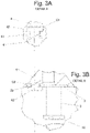
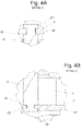
- Figures 3A-3B schematically show enlarged details of connections between the rod 6 and respectively the annular piston 4 and the shutter 2 when a regulation function is deactivated. Meanwhile, figures 4A-4B schematically show enlarged details of those connections between the rod 6 and respectively the annular piston 4 and the shutter 2 when the regulation function is activated.
- notches 61, 22 may bring the presence of some clearances C1, C2 in the area of connection of those notches 61, 62 to hole 22 and slot 42. These clearances may facilitate the assembling of the pump 1. Such clearances C1, C2 may vary depending on the status of the pump 1 as will be explained later.
- the first pressure chamber 51 may comprise an opening 55 to allow atmospheric air entering the first pressure chamber 51 and the second pressure chamber 52 may be associated with a vacuum source (not illustrated).
- the second pressure chamber 52 may comprise a vacuum connection 54 to allow the fluid connection to the vacuum source.
- the piston 4 may comprise a piston seal 41 for sealing the first 51 and the second 52 pressure chambers from each other.
- the piston seal 41 may be a lip seal or the like which may contact the walls of the annular groove 4.
- the adjustable coolant pump 1 may further comprise a resilient element 7 to push the annular piston 41 in axial direction and away from the impeller 14, wherein the resilient element 7 may be located in a corresponding accommodation 53 opened out to the annular groove 5.
- a plurality of resilient elements 7 such as three, around and parallel to the axis of rotation AR at 120° the one to the other.
- the resilient element 7 may comprise a spring, for instance.
- the shutter 2 may comprise at least one bore 21 to slidably receive the corresponding end-stop element 3.
- the number of bores 21 may be the same as the number of end-stop elements 3.
- the shank 31 with a predefined length it may be possible to easily adjust the reduction percentage above mentioned without adjusting the output delivered by the power source which drives the shaft 13, and/or without adjusting the vacuum source associated to the second pressure chamber 52.
- Figure 6 schematically shows a longitudinal cross section view of an adjustable coolant pump 1 according to a further example when a regulation function is deactivated and figure 7 schematically shows a longitudinal cross section view of the adjustable coolant pump 1 of the figure 6 when a regulation function is activated.
- the housing 12 may further comprise an annular wall 122 extending from the bottom face 16 in axial direction in such a way that a cavity 121 to receive the shutter 2 may be defined at least by the annular wall 122 and the bottom face 16; wherein the adjustable coolant pump 1 may further comprise an adjustment sealing arrangement provided between the shutter 2 and the annular wall 122, the sealing arrangement comprising a ring seal 123 attached either to the shutter 2 or the annular wall 122, in such a way that a dynamic sealing between the shutter 2 and the housing 12 may be defined.
- the dynamic sealing may be achieved along the stroke of the shutter 2
- the ring seal 123 may be disposed about the axis of rotation AR.
- the annular wall 12 may be integrally formed with the rest of the housing 12 or may be a separate part which can be attached to the rest of the housing 12.
- the ring seal 123 is attached to the annular wall 122.
- the ring seal 123 may be attached to the shutter 2, particularly in a sidewall of the cup-like shutter 2.
- the ring seal 123 may be attached either to the shutter 2 or the annular wall 122, there may be a relative motion between the ring seal 123 and the annular wall 122 or the shutter 2.
- Figure 8 schematically shows an enlarged detail E of an adjustment sealing arrangement of the adjustable coolant pump 1 of the figure 6 and figure 9 schematically shows an enlarged detail F of an adjustment sealing arrangement of the adjustable coolant pump 1 of the figure 7 .
- annular recces 125 in the annular wall 122 where the ring seal 123 may be received. More particularly, the annular recess 125 is formed in an inner face of the annular wall 122, the inner face forming the cavity 121 where the shutter 2 may be housed. The inner face is facing the shutter 2.
- the ring seal 123 may comprise a flange 124 or lip to contact the shutter 2.
- the ring seal 123 may be an O-ring, "X" or squared cross-section shaped or the like.
- the ring seal 123 may be manufactured from a resilient material.
- the flange 124 may protrude from the rest of ring seal 123 to obtain a better contact with the shutter 2.
- the flange 124 also protrudes from the inner wall of the annular wall 122.
- the ring seal 123 may be configured so as to allow an empty space 126 or void defined in the annular recess 125 and covered at least partially by the flange 124.
- the flange 124 may be received by the empty space 126 when it is bent due to the relative motion between the shutter 2 and the housing 12.
- Figure 5 is a flow chart of an exemplary method of operation of an adjustable coolant pump. Although figure 5 shows a specific sequence, it should be understood that other sequences may be followed not deviating from the scope of the present disclosure.
- the method of operation 100 may be related to the herein disclosed examples of adjustable coolant pump 1, for instance those examples which may comprise:
- the method 100 may comprise:
- the method 100 related, for instance, to those herein disclosed examples in which the adjustable coolant pump 1 may further comprise:
- the method 100 may further comprise: reducing the pressure 103 of the second pressure chamber 52 to at least one predefined level lower than the pressure of the first pressure chamber 1 for displacing the annular piston 4 in axial direction to the impeller 14 and covering, at least partially, the outflow region OR of the impeller 14 by the shutter 2.
- Reducing the pressure of the second pressure chamber 52 may comprise actuating a vacuum source (not illustrated) associated to the second pressure chamber 52 and allowing atmospheric air entering the first pressure chamber 51 through an opening 55 thereof.
- actuating the vacuum source for instance, a gas may be removed from the second pressure chamber 52. Meanwhile, the opening 55 may allow atmospheric air entering the first pressure chamber 51.
- the annular piston 4 may move in axial direction towards the impeller 14, so the size (volume) of the second pressure chamber 52 may become smaller than the first pressure chamber 51.
- the shutter 2 may be mechanically associated to the annular piston 4, the shutter 2 may describe a similar displacement.
- the pressure inside the second pressure chamber 52 may be kept below the atmospheric pressure of the environment of the pump 1.
- the regulation function may be deemed as not necessary it may be deactivated.
- the vacuum source may be no longer activated.
- the resilient elements 7 may displace the annular piston 4 away from the impeller 14 in axial direction.
- the force generated by the springs 15 may be lower than the force created by the vacuum pressure of the vacuum source when the regulation function is activated so as to displace the shutter 2 towards the impeller 14 and at the same time this force may be sufficient as to return both annular piston 4 and shutter or adjusting element 2 when regulation function is deactivated.
- the first pressure chamber 51 may become smaller than the second pressure chamber 52.
- the face of the shutter opposite to the impeller 14 may contact the bottom face 16 which may act as deactivation stroke limit.
- first 51 and the second 52 chambers may cause the displacement of the annular piston 4 in axial direction.
- first pressure chamber may be fed with air directly taken from the environment of the pump (for instance atmospheric air) or a gas at a pressure higher than the gas inside the second pressure chamber 52 may be forced to enter the first chamber 51.
- control unit may determine that a regulation of the flow-rate of the pump 1 may be activated.
- the control unit may send a command to the vacuum source to remove a predefined quantity of fluid form the second pressure chamber 52. This way, the outflow region OR may be at least partially occluded.
- an atmospheric pressure fluid such as ambient air
- an atmospheric pressure fluid may enter the first pressure chamber 51 or an atmospheric pressure fluid may be forced to enter.
- the force of the generated vacuum may be greater than the opposite force of the resilient elements 7 to displace the piston towards the impeller 14.
- the control unit may determine that the regulation function may be no longer needed, it may send a command to the vacuum source to stop generating vacuum.
- the atmospheric pressure fluid such as ambient air
- the vacuum connection 54 may be in fluid communication with an atmospheric air intake (not illustrated).
- the aperture/closure of the atmospheric air intake may be ruled by the control unit. This way, the difference of pressure between the first 51 and the second 52 chambers may no longer exist and both chambers 51, 52 may contain fluid at substantially the same pressure. Then resilient elements 7 may push the piston away from the impeller 14 in axial direction.
- the clearances C1, C2 may vary depending on the status of the pump 1. For instance, in figures 3A-3B the function may be deactivated but in figures 4A-4B activated.
- the size of the clearance C1, C2 may be the same in both cases but their distribution may vary like the size of the first and second pressure chambers 51, 52 by activation or deactivation of regulation.
- clearance C1, C2 may be larger in the connection area disposed closer to the impeller 14. Conversely, when the regulation is activated (see figures 3A-3B ), clearance C1, C2 may be larger in the connection area disposed farther from the impeller 14.
- an end of the stroke of the annular piston 4 and thus the shutter 2 may be accurately defined despite the clearances C1, C2 (for instance, when the regulation is activated). Furthermore, thanks to the bottom face 16, the other end of stroke of the annular piston 4 and thus the shutter 2 may be accurately defined despite the clearances C1, C2 (for instance, when the regulation is deactivated).
- a dynamic sealing may be achieved between the shutter 2 and the housing 12, more particularly, between the shutter 2 and the annular wall 122.
- a sealing function of the adjustment sealing arrangement may be maintained not only at the end points of the stroke of the shutter 2 but also along said stroke.
- the flange 124 may be bent or deformed when the shutter 2 is displaced along the axis of rotation AR.
- the adjustable coolant pump 1 may be configured to carry out the method 100.
Landscapes
- Engineering & Computer Science (AREA)
- Mechanical Engineering (AREA)
- General Engineering & Computer Science (AREA)
- Structures Of Non-Positive Displacement Pumps (AREA)
- Sorption Type Refrigeration Machines (AREA)
- Particle Accelerators (AREA)
- Magnetic Resonance Imaging Apparatus (AREA)
Claims (14)
- Une pompe d'agent de refroidissement réglable (1) comprenant :un boîtier (12) ;un arbre (13) pour tourner autour d'un axe de rotation (AR) du boîtier ;une roue hélice (14) assemblée dans l'arbre ;un capot de fermeture (2) déplaçable le long de l'axe de rotation pour couvrir, au moins en partie, une région de décharge (OR) de la roue hélice de telle sorte qu'une quantité de l'agent de refroidissement délivrée par la pompe est réglable ;au moins un élément de butée (3) fixé à une partie du boîtier pour définir une fin de course pour le capot de fermeture lorsqu'il couvre, au moins en partie, la région de décharge ;dans laquelle le boîtier comprend :une face supérieure (15) et une face inférieure (16) disposées essentiellement perpendiculairement à l'axe de rotation, la face inférieure étant fournie entre la face supérieure et le capot de fermeture ;dans laquelle l'élément de butée est fixé à la face inférieure ;caractérisée en ce que l'élément de butée comprend une tige (31) fixée d'une extrémité à la partie du boîtier et comprenant en outre un élargissement (32) de l'autre extrémité pour arrêter le capot de fermeture lorsqu'il couvre, au moins en partie, la région de décharge.
- La pompe d'agent de refroidissement réglable (1) selon la revendication 1, dans laquelle le boîtier comprend en outre une paroi annulaire (122) s'étendant depuis la face inférieure dans la direction axiale de telle manière qu'une cavité (121) pour recevoir le capot de fermeture est définie au moins par la paroi annulaire et la face inférieure ;
dans laquelle la pompe d'agent de refroidissement réglable comprend en outre :
un agencement de scellage de réglage fourni entre le capot de fermeture et la paroi annulaire, l'agencement de scellage comprenant un joint torique (123) fixé soit au capot de fermeture soit à la paroi annulaire, de telle manière qu'un scellage dynamique entre le capot de fermeture et le boîtier est défini. - La pompe d'agent de refroidissement réglable (1) selon la revendication 1, dans laquelle la tige a une longueur prédéfinie telle que la longueur prédéfinie de la tige correspond à une fin de course prédéfinie pour le capot de fermeture lorsqu'il couvre, au moins en partie, la région de décharge.
- La pompe d'agent de refroidissement réglable (1) selon l'une quelconque des revendications 1 à 2, dans laquelle l'élément de butée comprend un boulon ou un rivet.
- La pompe d'agent de refroidissement réglable (1) selon l'une quelconque des revendications 1 à 4, comprenant en outre :un piston annulaire (4) déplaçable dans la direction axiale ;une rainure annulaire (5) à l'intérieur de laquelle le piston annulaire est déplaçable ;dans laquelle la rainure annulaire est divisée en au moins une première (51) etune seconde (52) chambres de pression par le piston annulaire ;dans lequel le piston annulaire est relié mécaniquement au capot de fermeture de telle sorte qu'un déplacement du piston annulaire dans la direction axiale est transmis au capot de fermeture.
- La pompe d'agent de refroidissement réglable (1) selon la revendication 5, comprenant en outre au moins une barre (6) pour relier mécaniquement le piston annulaire au capot de fermeture.
- La pompe d'agent de refroidissement réglable (1) selon l'une quelconque des revendications 5 à 6, dans laquelle la première chambre de pression comprend une ouverture (55) pour permettre l'entrée d'air atmosphérique dans la première chambre de pression et la seconde chambre de pression est associée à une source de vide.
- La pompe d'agent de refroidissement réglable (1) selon l'une quelconque des revendications 5 à 7, dans laquelle le piston comprend un joint de piston (41) pour sceller les première et seconde chambres de pression l'une contre l'autre.
- La pompe d'agent de refroidissement réglable (1) selon l'une quelconque des revendications 5 à 8, comprenant en outre :
un élément élastique (7) pour pousser le piston annulaire dans la direction axiale et en direction opposée à la roue hélice, dans laquelle l'élément élastique est situé dans un logement correspondant ouvert sur la rainure annulaire. - La pompe d'agent de refroidissement réglable (1) selon la revendication 9, dans lequel l'élément élastique comprend un ressort.
- La pompe d'agent de refroidissement réglable (1) selon l'une quelconque des revendications 1 à 10, dans laquelle le capot de fermeture comprend au moins un alésage (21) pour recevoir de manière coulissante l'élément de butée correspondant.
- La pompe d'agent de refroidissement réglable (1) selon l'une quelconque des revendications 1 à 11, qui est actionnée pneumatiquement.
- Un procédé de fonctionnement (100) d'une pompe d'agent de refroidissement réglable (1), la pompe d'agent de refroidissement réglable comprenant :un boîtier (12) ;un arbre (13) pour tourner autour d'un axe de rotation (AR) du boîtier ;une roue hélice (14) assemblée dans l'arbre ;un capot de fermeture (2) déplaçable le long de l'axe de rotation pour couvrir, au moins en partie, une région de décharge (OR) de la roue hélice de telle sorte qu'une quantité de l'agent de refroidissement délivrée par la pompe est réglable ;au moins un élément de butée (3) fixé à une partie du boîtier pour définir une fin de course pour le capot de fermeture lorsqu'il couvre, au moins en partie, la région de décharge ;dans lequel le boîtier comprend :une face supérieure (15) et une face inférieure (16) disposées essentiellement perpendiculairement à l'axe de rotation, la face inférieure étant fournie entre la face supérieure et le capot de fermeture ;dans lequel l'élément de butée est fixé à la face inférieure ;dans lequel l'élément de butée comprend une tige (31) fixée d'une extrémité à la partie du boîtier et comprenant en outre un élargissement (32) de l'autre extrémité pour arrêter le capot de fermeture lorsqu'il couvre, au moins en partie, la région de décharge;dans lequel le procédé comprend :faire tourner l'arbre (101) pour faire tourner la roue hélice afin de mettre en mouvement une quantité d'agent de refroidissement ;déplacer le capot de fermeture (102) le long de l'axe de rotation pour couvrir, au moins en partie, la région de décharge de la roue hélice afin d'ajuster la quantité d'agent de refroidissement délivrée par la pompe ;arrêter le déplacement du capot de fermeture (104) à une fin de course prédéfinie au moyen de l'élément de butée, lorsque le capot de fermeture couvre, au moins en partie, la région de décharge.
- Le procédé selon la revendication 13, la pompe d'agent de refroidissement réglable (1) comprenant en outre :un piston annulaire (4) déplaçable dans la direction axiale ;une rainure annulaire (5) à l'intérieur de laquelle le piston annulaire est déplaçable ;dans lequel la rainure annulaire est divisée en au moins une première (51) et une seconde (52) chambres de pression par le piston annulaire ;dans lequel le piston annulaire est relié mécaniquement au capot de fermeture de telle sorte qu'un déplacement du piston annulaire dans la direction axiale est transmis au capot de fermeture ;dans lequel le procédé comprend en outre :réduire la pression (103) de la seconde chambre de pression à au moins un niveau prédéfini inférieur à la pression de la première chambre de pression pour déplacer le piston annulaire dans la direction axiale vers la roue hélice et couvrir, au moins en partie, la région de décharge de la roue hélice moyennant le capot de fermeture ;dans lequel la réduction de la pression de la seconde chambre de pression comprend l'actionnement d'une source de vide associée à la seconde chambre de pression et l'admission d'air atmosphérique dans la première chambre de pression à travers une ouverture de celle-ci.
Priority Applications (1)
| Application Number | Priority Date | Filing Date | Title |
|---|---|---|---|
| EP18382968.8A EP3597925B1 (fr) | 2018-07-16 | 2018-12-21 | Pompe de refroidissement réglable |
Applications Claiming Priority (1)
| Application Number | Priority Date | Filing Date | Title |
|---|---|---|---|
| EP17382466 | 2017-07-17 |
Publications (2)
| Publication Number | Publication Date |
|---|---|
| EP3431768A1 EP3431768A1 (fr) | 2019-01-23 |
| EP3431768B1 true EP3431768B1 (fr) | 2022-03-30 |
Family
ID=59506218
Family Applications (1)
| Application Number | Title | Priority Date | Filing Date |
|---|---|---|---|
| EP18382529.8A Not-in-force EP3431768B1 (fr) | 2017-07-17 | 2018-07-16 | Pompe de refroidissement réglable |
Country Status (2)
| Country | Link |
|---|---|
| EP (1) | EP3431768B1 (fr) |
| ES (1) | ES2921006T3 (fr) |
Families Citing this family (4)
| Publication number | Priority date | Publication date | Assignee | Title |
|---|---|---|---|---|
| DE102019122717A1 (de) * | 2019-08-23 | 2021-02-25 | Nidec Gpm Gmbh | Regelbare Kühlmittelpumpe mit Kolbenstangenführung |
| DE102019122718A1 (de) * | 2019-08-23 | 2021-02-25 | Nidec Gpm Gmbh | Kolbenstangenabdichtung |
| CN112179438A (zh) * | 2020-09-30 | 2021-01-05 | 湖南常德牌水表制造有限公司 | 一种方便误差调节的水表 |
| US12276222B2 (en) | 2021-05-20 | 2025-04-15 | Pierburg Pump Technology Gmbh | Controllable mechanical motor vehicle coolant pump |
Family Cites Families (6)
| Publication number | Priority date | Publication date | Assignee | Title |
|---|---|---|---|---|
| BE793550A (fr) * | 1971-12-29 | 1973-04-16 | Gen Electric | Pompe centrifuge a diffuseur reglable |
| DE102005062200B3 (de) | 2005-12-23 | 2007-02-22 | Geräte- und Pumpenbau GmbH Dr. Eugen Schmidt | Regelbare Kühlmittelpumpe |
| DE102011052678A1 (de) * | 2011-08-12 | 2013-02-14 | Dr. Ing. H.C. F. Porsche Aktiengesellschaft | Kühlmittelpumpe für einen Kühlkreislauf einer Brennkraftmaschine sowie Ver-wendung einer solchen Kühlmittelpumpe |
| DE102013111939B3 (de) * | 2013-10-30 | 2014-10-30 | Pierburg Gmbh | Kühlmittelpumpe für den Einsatz im KFZ-Bereich |
| DE102015000805B3 (de) * | 2015-01-22 | 2016-01-21 | Nidec Gpm Gmbh | Regelbare Kühlmittelpumpe |
| DE102015106669B4 (de) * | 2015-04-29 | 2025-10-23 | Dr. Ing. H.C. F. Porsche Aktiengesellschaft | Pumpe |
-
2018
- 2018-07-16 EP EP18382529.8A patent/EP3431768B1/fr not_active Not-in-force
- 2018-07-16 ES ES18382529T patent/ES2921006T3/es active Active
Also Published As
| Publication number | Publication date |
|---|---|
| ES2921006T3 (es) | 2022-08-16 |
| EP3431768A1 (fr) | 2019-01-23 |
Similar Documents
| Publication | Publication Date | Title |
|---|---|---|
| EP3431768B1 (fr) | Pompe de refroidissement réglable | |
| JP7341621B2 (ja) | 容量制御弁 | |
| CN108350886B (zh) | 用于机动车领域的冷却剂泵 | |
| EP3181903B1 (fr) | Soupape de contrôle de compresseur à capacité variable | |
| US6758657B1 (en) | Electromagnetically driven diaphragm pump | |
| JP6402426B2 (ja) | 可変容量圧縮機 | |
| US20200057458A1 (en) | Control valve for variable displacement compressor | |
| EP3521616A1 (fr) | Soupape de commande pour compresseur à capacité variable | |
| KR102744360B1 (ko) | 용량 제어 밸브 | |
| JP6647540B2 (ja) | 内燃機関の機械的に調整可能な冷却媒体ポンプのための調整ユニット | |
| JP2018532944A (ja) | 内燃機関用冷却媒体ポンプ | |
| JP2006527328A (ja) | 内燃機関用カムシャフトアジャスタ | |
| JP4651049B2 (ja) | 改善された効率を備えたピストンポンプ | |
| KR102252391B1 (ko) | 가변 용량 압축기 및 그 제어 밸브 | |
| JP4469856B2 (ja) | 戻しばねのためのコンパクトな保持装置を有するピストンポンプ | |
| EP3597925B1 (fr) | Pompe de refroidissement réglable | |
| KR102744357B1 (ko) | 용량 제어 밸브 | |
| KR101021532B1 (ko) | 브레이크 시스템의 펌프 | |
| JP2016169700A (ja) | 可変容量圧縮機 | |
| US12448955B2 (en) | Displacement control for hydraulic pump | |
| US10233795B2 (en) | Bypass valve for pressure oscillation control | |
| US11965609B2 (en) | Valve for preventing backflow and valve module | |
| JP6469994B2 (ja) | 圧縮機 | |
| CN112334653A (zh) | 可变容量压缩机 | |
| JP7185568B2 (ja) | 可変容量圧縮機 |
Legal Events
| Date | Code | Title | Description |
|---|---|---|---|
| PUAI | Public reference made under article 153(3) epc to a published international application that has entered the european phase |
Free format text: ORIGINAL CODE: 0009012 |
|
| STAA | Information on the status of an ep patent application or granted ep patent |
Free format text: STATUS: THE APPLICATION HAS BEEN PUBLISHED |
|
| AK | Designated contracting states |
Kind code of ref document: A1 Designated state(s): AL AT BE BG CH CY CZ DE DK EE ES FI FR GB GR HR HU IE IS IT LI LT LU LV MC MK MT NL NO PL PT RO RS SE SI SK SM TR |
|
| AX | Request for extension of the european patent |
Extension state: BA ME |
|
| STAA | Information on the status of an ep patent application or granted ep patent |
Free format text: STATUS: REQUEST FOR EXAMINATION WAS MADE |
|
| 17P | Request for examination filed |
Effective date: 20190723 |
|
| RBV | Designated contracting states (corrected) |
Designated state(s): AL AT BE BG CH CY CZ DE DK EE ES FI FR GB GR HR HU IE IS IT LI LT LU LV MC MK MT NL NO PL PT RO RS SE SI SK SM TR |
|
| GRAP | Despatch of communication of intention to grant a patent |
Free format text: ORIGINAL CODE: EPIDOSNIGR1 |
|
| STAA | Information on the status of an ep patent application or granted ep patent |
Free format text: STATUS: GRANT OF PATENT IS INTENDED |
|
| INTG | Intention to grant announced |
Effective date: 20211117 |
|
| GRAS | Grant fee paid |
Free format text: ORIGINAL CODE: EPIDOSNIGR3 |
|
| GRAA | (expected) grant |
Free format text: ORIGINAL CODE: 0009210 |
|
| STAA | Information on the status of an ep patent application or granted ep patent |
Free format text: STATUS: THE PATENT HAS BEEN GRANTED |
|
| AK | Designated contracting states |
Kind code of ref document: B1 Designated state(s): AL AT BE BG CH CY CZ DE DK EE ES FI FR GB GR HR HU IE IS IT LI LT LU LV MC MK MT NL NO PL PT RO RS SE SI SK SM TR |
|
| REG | Reference to a national code |
Ref country code: GB Ref legal event code: FG4D |
|
| REG | Reference to a national code |
Ref country code: CH Ref legal event code: EP |
|
| REG | Reference to a national code |
Ref country code: DE Ref legal event code: R096 Ref document number: 602018032914 Country of ref document: DE |
|
| REG | Reference to a national code |
Ref country code: AT Ref legal event code: REF Ref document number: 1479433 Country of ref document: AT Kind code of ref document: T Effective date: 20220415 |
|
| REG | Reference to a national code |
Ref country code: IE Ref legal event code: FG4D |
|
| REG | Reference to a national code |
Ref country code: LT Ref legal event code: MG9D |
|
| PG25 | Lapsed in a contracting state [announced via postgrant information from national office to epo] |
Ref country code: SE Free format text: LAPSE BECAUSE OF FAILURE TO SUBMIT A TRANSLATION OF THE DESCRIPTION OR TO PAY THE FEE WITHIN THE PRESCRIBED TIME-LIMIT Effective date: 20220330 Ref country code: RS Free format text: LAPSE BECAUSE OF FAILURE TO SUBMIT A TRANSLATION OF THE DESCRIPTION OR TO PAY THE FEE WITHIN THE PRESCRIBED TIME-LIMIT Effective date: 20220330 Ref country code: NO Free format text: LAPSE BECAUSE OF FAILURE TO SUBMIT A TRANSLATION OF THE DESCRIPTION OR TO PAY THE FEE WITHIN THE PRESCRIBED TIME-LIMIT Effective date: 20220630 Ref country code: LT Free format text: LAPSE BECAUSE OF FAILURE TO SUBMIT A TRANSLATION OF THE DESCRIPTION OR TO PAY THE FEE WITHIN THE PRESCRIBED TIME-LIMIT Effective date: 20220330 Ref country code: HR Free format text: LAPSE BECAUSE OF FAILURE TO SUBMIT A TRANSLATION OF THE DESCRIPTION OR TO PAY THE FEE WITHIN THE PRESCRIBED TIME-LIMIT Effective date: 20220330 Ref country code: BG Free format text: LAPSE BECAUSE OF FAILURE TO SUBMIT A TRANSLATION OF THE DESCRIPTION OR TO PAY THE FEE WITHIN THE PRESCRIBED TIME-LIMIT Effective date: 20220630 |
|
| REG | Reference to a national code |
Ref country code: NL Ref legal event code: MP Effective date: 20220330 |
|
| REG | Reference to a national code |
Ref country code: AT Ref legal event code: MK05 Ref document number: 1479433 Country of ref document: AT Kind code of ref document: T Effective date: 20220330 |
|
| REG | Reference to a national code |
Ref country code: ES Ref legal event code: FG2A Ref document number: 2921006 Country of ref document: ES Kind code of ref document: T3 Effective date: 20220816 |
|
| PG25 | Lapsed in a contracting state [announced via postgrant information from national office to epo] |
Ref country code: LV Free format text: LAPSE BECAUSE OF FAILURE TO SUBMIT A TRANSLATION OF THE DESCRIPTION OR TO PAY THE FEE WITHIN THE PRESCRIBED TIME-LIMIT Effective date: 20220330 Ref country code: GR Free format text: LAPSE BECAUSE OF FAILURE TO SUBMIT A TRANSLATION OF THE DESCRIPTION OR TO PAY THE FEE WITHIN THE PRESCRIBED TIME-LIMIT Effective date: 20220701 Ref country code: FI Free format text: LAPSE BECAUSE OF FAILURE TO SUBMIT A TRANSLATION OF THE DESCRIPTION OR TO PAY THE FEE WITHIN THE PRESCRIBED TIME-LIMIT Effective date: 20220330 |
|
| PG25 | Lapsed in a contracting state [announced via postgrant information from national office to epo] |
Ref country code: NL Free format text: LAPSE BECAUSE OF FAILURE TO SUBMIT A TRANSLATION OF THE DESCRIPTION OR TO PAY THE FEE WITHIN THE PRESCRIBED TIME-LIMIT Effective date: 20220330 |
|
| PG25 | Lapsed in a contracting state [announced via postgrant information from national office to epo] |
Ref country code: SM Free format text: LAPSE BECAUSE OF FAILURE TO SUBMIT A TRANSLATION OF THE DESCRIPTION OR TO PAY THE FEE WITHIN THE PRESCRIBED TIME-LIMIT Effective date: 20220330 Ref country code: SK Free format text: LAPSE BECAUSE OF FAILURE TO SUBMIT A TRANSLATION OF THE DESCRIPTION OR TO PAY THE FEE WITHIN THE PRESCRIBED TIME-LIMIT Effective date: 20220330 Ref country code: RO Free format text: LAPSE BECAUSE OF FAILURE TO SUBMIT A TRANSLATION OF THE DESCRIPTION OR TO PAY THE FEE WITHIN THE PRESCRIBED TIME-LIMIT Effective date: 20220330 Ref country code: PT Free format text: LAPSE BECAUSE OF FAILURE TO SUBMIT A TRANSLATION OF THE DESCRIPTION OR TO PAY THE FEE WITHIN THE PRESCRIBED TIME-LIMIT Effective date: 20220801 Ref country code: EE Free format text: LAPSE BECAUSE OF FAILURE TO SUBMIT A TRANSLATION OF THE DESCRIPTION OR TO PAY THE FEE WITHIN THE PRESCRIBED TIME-LIMIT Effective date: 20220330 Ref country code: CZ Free format text: LAPSE BECAUSE OF FAILURE TO SUBMIT A TRANSLATION OF THE DESCRIPTION OR TO PAY THE FEE WITHIN THE PRESCRIBED TIME-LIMIT Effective date: 20220330 Ref country code: AT Free format text: LAPSE BECAUSE OF FAILURE TO SUBMIT A TRANSLATION OF THE DESCRIPTION OR TO PAY THE FEE WITHIN THE PRESCRIBED TIME-LIMIT Effective date: 20220330 |
|
| PG25 | Lapsed in a contracting state [announced via postgrant information from national office to epo] |
Ref country code: PL Free format text: LAPSE BECAUSE OF FAILURE TO SUBMIT A TRANSLATION OF THE DESCRIPTION OR TO PAY THE FEE WITHIN THE PRESCRIBED TIME-LIMIT Effective date: 20220330 Ref country code: IS Free format text: LAPSE BECAUSE OF FAILURE TO SUBMIT A TRANSLATION OF THE DESCRIPTION OR TO PAY THE FEE WITHIN THE PRESCRIBED TIME-LIMIT Effective date: 20220730 Ref country code: AL Free format text: LAPSE BECAUSE OF FAILURE TO SUBMIT A TRANSLATION OF THE DESCRIPTION OR TO PAY THE FEE WITHIN THE PRESCRIBED TIME-LIMIT Effective date: 20220330 |
|
| REG | Reference to a national code |
Ref country code: DE Ref legal event code: R097 Ref document number: 602018032914 Country of ref document: DE |
|
| PG25 | Lapsed in a contracting state [announced via postgrant information from national office to epo] |
Ref country code: DK Free format text: LAPSE BECAUSE OF FAILURE TO SUBMIT A TRANSLATION OF THE DESCRIPTION OR TO PAY THE FEE WITHIN THE PRESCRIBED TIME-LIMIT Effective date: 20220330 |
|
| PLBE | No opposition filed within time limit |
Free format text: ORIGINAL CODE: 0009261 |
|
| STAA | Information on the status of an ep patent application or granted ep patent |
Free format text: STATUS: NO OPPOSITION FILED WITHIN TIME LIMIT |
|
| PG25 | Lapsed in a contracting state [announced via postgrant information from national office to epo] |
Ref country code: MC Free format text: LAPSE BECAUSE OF FAILURE TO SUBMIT A TRANSLATION OF THE DESCRIPTION OR TO PAY THE FEE WITHIN THE PRESCRIBED TIME-LIMIT Effective date: 20220330 |
|
| REG | Reference to a national code |
Ref country code: CH Ref legal event code: PL |
|
| 26N | No opposition filed |
Effective date: 20230103 |
|
| REG | Reference to a national code |
Ref country code: BE Ref legal event code: MM Effective date: 20220731 |
|
| PG25 | Lapsed in a contracting state [announced via postgrant information from national office to epo] |
Ref country code: LU Free format text: LAPSE BECAUSE OF NON-PAYMENT OF DUE FEES Effective date: 20220716 Ref country code: LI Free format text: LAPSE BECAUSE OF NON-PAYMENT OF DUE FEES Effective date: 20220731 Ref country code: CH Free format text: LAPSE BECAUSE OF NON-PAYMENT OF DUE FEES Effective date: 20220731 |
|
| PG25 | Lapsed in a contracting state [announced via postgrant information from national office to epo] |
Ref country code: SI Free format text: LAPSE BECAUSE OF FAILURE TO SUBMIT A TRANSLATION OF THE DESCRIPTION OR TO PAY THE FEE WITHIN THE PRESCRIBED TIME-LIMIT Effective date: 20220330 Ref country code: BE Free format text: LAPSE BECAUSE OF NON-PAYMENT OF DUE FEES Effective date: 20220731 |
|
| PG25 | Lapsed in a contracting state [announced via postgrant information from national office to epo] |
Ref country code: IE Free format text: LAPSE BECAUSE OF NON-PAYMENT OF DUE FEES Effective date: 20220716 |
|
| PGFP | Annual fee paid to national office [announced via postgrant information from national office to epo] |
Ref country code: IT Payment date: 20230720 Year of fee payment: 6 Ref country code: GB Payment date: 20230727 Year of fee payment: 6 Ref country code: ES Payment date: 20230801 Year of fee payment: 6 |
|
| PGFP | Annual fee paid to national office [announced via postgrant information from national office to epo] |
Ref country code: FR Payment date: 20230725 Year of fee payment: 6 Ref country code: DE Payment date: 20230727 Year of fee payment: 6 |
|
| PG25 | Lapsed in a contracting state [announced via postgrant information from national office to epo] |
Ref country code: HU Free format text: LAPSE BECAUSE OF FAILURE TO SUBMIT A TRANSLATION OF THE DESCRIPTION OR TO PAY THE FEE WITHIN THE PRESCRIBED TIME-LIMIT; INVALID AB INITIO Effective date: 20180716 |
|
| PG25 | Lapsed in a contracting state [announced via postgrant information from national office to epo] |
Ref country code: MK Free format text: LAPSE BECAUSE OF FAILURE TO SUBMIT A TRANSLATION OF THE DESCRIPTION OR TO PAY THE FEE WITHIN THE PRESCRIBED TIME-LIMIT Effective date: 20220330 Ref country code: CY Free format text: LAPSE BECAUSE OF FAILURE TO SUBMIT A TRANSLATION OF THE DESCRIPTION OR TO PAY THE FEE WITHIN THE PRESCRIBED TIME-LIMIT Effective date: 20220330 |
|
| PG25 | Lapsed in a contracting state [announced via postgrant information from national office to epo] |
Ref country code: TR Free format text: LAPSE BECAUSE OF FAILURE TO SUBMIT A TRANSLATION OF THE DESCRIPTION OR TO PAY THE FEE WITHIN THE PRESCRIBED TIME-LIMIT Effective date: 20220330 |
|
| PG25 | Lapsed in a contracting state [announced via postgrant information from national office to epo] |
Ref country code: MT Free format text: LAPSE BECAUSE OF FAILURE TO SUBMIT A TRANSLATION OF THE DESCRIPTION OR TO PAY THE FEE WITHIN THE PRESCRIBED TIME-LIMIT Effective date: 20220330 |
|
| REG | Reference to a national code |
Ref country code: DE Ref legal event code: R119 Ref document number: 602018032914 Country of ref document: DE |
|
| GBPC | Gb: european patent ceased through non-payment of renewal fee |
Effective date: 20240716 |
|
| PG25 | Lapsed in a contracting state [announced via postgrant information from national office to epo] |
Ref country code: DE Free format text: LAPSE BECAUSE OF NON-PAYMENT OF DUE FEES Effective date: 20250201 |
|
| PG25 | Lapsed in a contracting state [announced via postgrant information from national office to epo] |
Ref country code: FR Free format text: LAPSE BECAUSE OF NON-PAYMENT OF DUE FEES Effective date: 20240731 |
|
| PG25 | Lapsed in a contracting state [announced via postgrant information from national office to epo] |
Ref country code: GB Free format text: LAPSE BECAUSE OF NON-PAYMENT OF DUE FEES Effective date: 20240716 |
|
| PG25 | Lapsed in a contracting state [announced via postgrant information from national office to epo] |
Ref country code: IT Free format text: LAPSE BECAUSE OF NON-PAYMENT OF DUE FEES Effective date: 20240716 |
|
| REG | Reference to a national code |
Ref country code: ES Ref legal event code: FD2A Effective date: 20250829 |
|
| PG25 | Lapsed in a contracting state [announced via postgrant information from national office to epo] |
Ref country code: ES Free format text: LAPSE BECAUSE OF NON-PAYMENT OF DUE FEES Effective date: 20240717 |