EP3431894A1 - Structure de stabilisation d'écoulement et dispositif de ventilation utilisant celui-ci - Google Patents
Structure de stabilisation d'écoulement et dispositif de ventilation utilisant celui-ci Download PDFInfo
- Publication number
- EP3431894A1 EP3431894A1 EP16884243.3A EP16884243A EP3431894A1 EP 3431894 A1 EP3431894 A1 EP 3431894A1 EP 16884243 A EP16884243 A EP 16884243A EP 3431894 A1 EP3431894 A1 EP 3431894A1
- Authority
- EP
- European Patent Office
- Prior art keywords
- air
- air supply
- flow
- work chamber
- airflow
- Prior art date
- Legal status (The legal status is an assumption and is not a legal conclusion. Google has not performed a legal analysis and makes no representation as to the accuracy of the status listed.)
- Withdrawn
Links
Images




Classifications
-
- B—PERFORMING OPERATIONS; TRANSPORTING
- B08—CLEANING
- B08B—CLEANING IN GENERAL; PREVENTION OF FOULING IN GENERAL
- B08B15/00—Preventing escape of dirt or fumes from the area where they are produced; Collecting or removing dirt or fumes from that area
- B08B15/02—Preventing escape of dirt or fumes from the area where they are produced; Collecting or removing dirt or fumes from that area using chambers or hoods covering the area
-
- B—PERFORMING OPERATIONS; TRANSPORTING
- B08—CLEANING
- B08B—CLEANING IN GENERAL; PREVENTION OF FOULING IN GENERAL
- B08B15/00—Preventing escape of dirt or fumes from the area where they are produced; Collecting or removing dirt or fumes from that area
- B08B15/02—Preventing escape of dirt or fumes from the area where they are produced; Collecting or removing dirt or fumes from that area using chambers or hoods covering the area
- B08B15/023—Fume cabinets or cupboards, e.g. for laboratories
-
- F—MECHANICAL ENGINEERING; LIGHTING; HEATING; WEAPONS; BLASTING
- F24—HEATING; RANGES; VENTILATING
- F24F—AIR-CONDITIONING; AIR-HUMIDIFICATION; VENTILATION; USE OF AIR CURRENTS FOR SCREENING
- F24F13/00—Details common to, or for air-conditioning, air-humidification, ventilation or use of air currents for screening
- F24F13/08—Air-flow control members, e.g. louvres, grilles, flaps or guide plates
-
- F—MECHANICAL ENGINEERING; LIGHTING; HEATING; WEAPONS; BLASTING
- F24—HEATING; RANGES; VENTILATING
- F24F—AIR-CONDITIONING; AIR-HUMIDIFICATION; VENTILATION; USE OF AIR CURRENTS FOR SCREENING
- F24F13/00—Details common to, or for air-conditioning, air-humidification, ventilation or use of air currents for screening
- F24F13/08—Air-flow control members, e.g. louvres, grilles, flaps or guide plates
- F24F13/081—Air-flow control members, e.g. louvres, grilles, flaps or guide plates for guiding air around a curve
-
- F—MECHANICAL ENGINEERING; LIGHTING; HEATING; WEAPONS; BLASTING
- F24—HEATING; RANGES; VENTILATING
- F24F—AIR-CONDITIONING; AIR-HUMIDIFICATION; VENTILATION; USE OF AIR CURRENTS FOR SCREENING
- F24F13/00—Details common to, or for air-conditioning, air-humidification, ventilation or use of air currents for screening
- F24F13/08—Air-flow control members, e.g. louvres, grilles, flaps or guide plates
- F24F13/082—Grilles, registers or guards
-
- F—MECHANICAL ENGINEERING; LIGHTING; HEATING; WEAPONS; BLASTING
- F24—HEATING; RANGES; VENTILATING
- F24F—AIR-CONDITIONING; AIR-HUMIDIFICATION; VENTILATION; USE OF AIR CURRENTS FOR SCREENING
- F24F13/00—Details common to, or for air-conditioning, air-humidification, ventilation or use of air currents for screening
- F24F13/08—Air-flow control members, e.g. louvres, grilles, flaps or guide plates
- F24F13/10—Air-flow control members, e.g. louvres, grilles, flaps or guide plates movable, e.g. dampers
-
- F—MECHANICAL ENGINEERING; LIGHTING; HEATING; WEAPONS; BLASTING
- F24—HEATING; RANGES; VENTILATING
- F24F—AIR-CONDITIONING; AIR-HUMIDIFICATION; VENTILATION; USE OF AIR CURRENTS FOR SCREENING
- F24F13/00—Details common to, or for air-conditioning, air-humidification, ventilation or use of air currents for screening
- F24F13/20—Casings or covers
-
- F—MECHANICAL ENGINEERING; LIGHTING; HEATING; WEAPONS; BLASTING
- F24—HEATING; RANGES; VENTILATING
- F24F—AIR-CONDITIONING; AIR-HUMIDIFICATION; VENTILATION; USE OF AIR CURRENTS FOR SCREENING
- F24F3/00—Air-conditioning systems in which conditioned primary air is supplied from one or more central stations to distributing units in the rooms or spaces where it may receive secondary treatment; Apparatus specially designed for such systems
- F24F3/12—Air-conditioning systems in which conditioned primary air is supplied from one or more central stations to distributing units in the rooms or spaces where it may receive secondary treatment; Apparatus specially designed for such systems characterised by the treatment of the air otherwise than by heating and cooling
- F24F3/16—Air-conditioning systems in which conditioned primary air is supplied from one or more central stations to distributing units in the rooms or spaces where it may receive secondary treatment; Apparatus specially designed for such systems characterised by the treatment of the air otherwise than by heating and cooling by purification, e.g. by filtering; by sterilisation; by ozonisation
- F24F3/163—Clean air work stations, i.e. selected areas within a space which filtered air is passed
-
- F—MECHANICAL ENGINEERING; LIGHTING; HEATING; WEAPONS; BLASTING
- F24—HEATING; RANGES; VENTILATING
- F24F—AIR-CONDITIONING; AIR-HUMIDIFICATION; VENTILATION; USE OF AIR CURRENTS FOR SCREENING
- F24F7/00—Ventilation
- F24F7/04—Ventilation with ducting systems, e.g. by double walls; with natural circulation
- F24F7/06—Ventilation with ducting systems, e.g. by double walls; with natural circulation with forced air circulation, e.g. by fan positioning of a ventilator in or against a conduit
-
- B—PERFORMING OPERATIONS; TRANSPORTING
- B08—CLEANING
- B08B—CLEANING IN GENERAL; PREVENTION OF FOULING IN GENERAL
- B08B2215/00—Preventing escape of dirt or fumes from the area where they are produced; Collecting or removing dirt or fumes from that area
- B08B2215/003—Preventing escape of dirt or fumes from the area where they are produced; Collecting or removing dirt or fumes from that area with the assistance of blowing nozzles
-
- F—MECHANICAL ENGINEERING; LIGHTING; HEATING; WEAPONS; BLASTING
- F24—HEATING; RANGES; VENTILATING
- F24F—AIR-CONDITIONING; AIR-HUMIDIFICATION; VENTILATION; USE OF AIR CURRENTS FOR SCREENING
- F24F13/00—Details common to, or for air-conditioning, air-humidification, ventilation or use of air currents for screening
- F24F13/24—Means for preventing or suppressing noise
-
- F—MECHANICAL ENGINEERING; LIGHTING; HEATING; WEAPONS; BLASTING
- F24—HEATING; RANGES; VENTILATING
- F24F—AIR-CONDITIONING; AIR-HUMIDIFICATION; VENTILATION; USE OF AIR CURRENTS FOR SCREENING
- F24F13/00—Details common to, or for air-conditioning, air-humidification, ventilation or use of air currents for screening
- F24F13/08—Air-flow control members, e.g. louvres, grilles, flaps or guide plates
- F24F13/082—Grilles, registers or guards
- F24F2013/088—Air-flow straightener
-
- F—MECHANICAL ENGINEERING; LIGHTING; HEATING; WEAPONS; BLASTING
- F24—HEATING; RANGES; VENTILATING
- F24F—AIR-CONDITIONING; AIR-HUMIDIFICATION; VENTILATION; USE OF AIR CURRENTS FOR SCREENING
- F24F2221/00—Details or features not otherwise provided for
- F24F2221/02—Details or features not otherwise provided for combined with lighting fixtures
Definitions
- the present invention relates to a ventilation apparatus for industrial or commercial use. More specifically the invention relates to an air supplying type ventilation apparatus with a steady flow structure used in the ventilation apparatus.
- Ventilation apparatus is generally described as apparatus for removing gases, such as exhaust gases, harmful gases and particulates, from work spaces to outside (usually outdoors), and the apparatus is widely used in both industry and daily life.
- gases such as exhaust gases, harmful gases and particulates
- the apparatus is widely used in both industry and daily life.
- gases such as exhaust gases, harmful gases and particulates
- a hood is provided with a work chamber (work space enclosure) to contain and dispose harmful airborne substances, and large amounts of ambient indoor air is supplied into the work chamber through a front opening of the hood while a high-power fan exhausts air from the work chamber.
- a high-power fan exhausts air from the work chamber.
- buildings equipped with the conventional ventilation apparatus consume enormous amounts of air conditioning energy.
- unpredictable and inconsistent airflow patterns such as turbulent vortexes, frequently form around the front opening of the hood and the exhaust outlet.
- Patent ZL201520216778.6 discloses a fume hood (ventilation apparatus), wherein by providing air supply outlets at the upper or lower side of the hood, supply airflow obtained from the air supply system of the building is blown into the work chamber of the fume hood.
- This design may significantly reduce the energy consumption of building air conditioning due to the air supply structure.
- the supply airflows from air supply outlets may flow in arbitrary directions, and the supply airflows flow freely in the air supply duct, as a result, a large proportion of the supply airflows flowing out of the air supply outlets would be turbulent or disturbed flows.
- all the flow-guiding plates in the steady flow structure provided by the present invention are arranged in a straight line with constant intervals.
- the steady flow structure provided by the present invention as described above can create a significant steady flow effect on airflow in the duct, and reduce airflow noise levels, thereby providing a smooth and steady airflow output.
- the present invention provides a ventilation apparatus, comprised of: a hood arranged indoors, an inner chamber of the hood constituting a work chamber, with the front wall of the hood being formed with a front opening facing towards the indoor environment; an air supply duct, which supplies air into the work chamber through air supply outlets which are provided on the hood extending in the left and right width direction of the work chamber; and an air exhaust duct, through which air entering into the work chamber through the front opening and air entering the work chamber through the air supply outlets are exhausted from the work chamber to outside; a steady flow structure is provided in the interior of the air supply duct and the steady flow structure is comprised of multiple flow-guiding plates formed in a substantial L-shape, each flow-guiding plate includes an air catching plate which is one side of the L-shape and a longitudinal plate which is the other side of the L-shape; wherein, all of the flow-guiding plates are arranged in a straight line, with longitudinal plates of the flow-guiding plates being arranged in parallel with each other and all of
- two of the aforementioned steady flow structures are provided symmetrically in left and right at the interior of the air supply outlet, and the two steady flow structures are arranged in a straight line and form a configuration having a larger height in the middle than at left and right ends; the supply airflow is supplied into the left and right ends, respectively, and then, after flowing through the steady flow structures, blows out evenly and stably from the air supply outlets located along the sides of the two steady flow structures.
- a central separator plate is provided between the two steady flow structures, at the center position of the straight line, and is provided in parallel with the longitudinal plates of all the flow-guiding plates.
- Each side of the central separator plate is seamlessly jointed to walls constituting the air supply duct, such that supply airflow entering the steady flow structures from the left direction and from the right direction are separated from each other.
- the ventilation apparatus provided by the present invention further comprises another air supply outlet located at the lower portion of the front opening of the work chamber, wherein said another air supply outlet supplies air towards the interior of the work chamber.
- the steady flow structure further comprises of air outlet guide plates orthogonal to the longitudinal plates of all of the flow-guiding plates and inside the air supply outlet, so as to change the direction from which the airflow enters out from the air supply outlet.
- the ventilation apparatus provided by the present invention further comprises a third air supply outlet located at the upper portion of the front opening of the work chamber and outside of the work chamber, wherein the third air supply outlet supplies the air downwardly.
- each air supply outlet is provided with a mesh grille for covering the air supply outlet.
- the another air supply outlet described above is further provided with a mesh screen covering the mesh grille, each screen hole of the mesh screen has a smaller area than each grille hole of the mesh grille, thereby preventing foreign objects from falling into the another air supply outlet.
- left and right side walls of the hood are hollow structures respectively, connecting the air supply inlet with the air supply outlet located at the lower portion of the work chamber.
- the air exhaust duct is located within the work chamber and near the rear portion of the hood, the air exhaust duct extends in left-right width direction of the work chamber, an air exhaust outlet of the air exhaust duct is provided above the work chamber, thereby the airflow entering into the air exhaust duct is exhausted to the outside of the work chamber.
- the air exhaust duct is constituted by the hood and three air baffles, which are an upper, a middle and a lower air baffle at the rear portion of the work chamber, wherein the lower air baffle is vertically arranged at the lower portion of the lower chamber, with a plurality of through holes perforating the lower air baffle, and the plurality of through holes are distributed over the entire left-right width direction of the lower air baffle;
- the middle air baffle is located above the lower air baffle, and is provided obliquely in the direction towards the rear wall of the hood;
- the upper air baffle is located above the middle air baffle, and is provided obliquely in the direction towards the upper wall of the hood; gaps are provided between the three air baffles, and between the three air baffles and inner walls of the hood; airflow in the work chamber flows into the air exhaust duct through the aformentioned through holes and the gaps, and is exhausted through the air exhaust outlet to outdoors.
- the work chamber is provided with an inclined top wall, which is provided from the one air supply outlet towards the upper air baffle gap between the top wall of the hood.
- a work light is provided within the inclined top wall for illuminating the work chamber.
- the flow-guiding plates provided in a straight line on the steady flow structure divides and regulates the supply airflow, greatly reducing the proportion of turbulent flow in the supply airflow;
- the air outlet guide plate provided on the steady flow structure further defines the directions of the airflow blowing out from the air supply outlets, therefore, a stable airflow that has been divided and regulated is delivered into the work chamber in desired directions;
- the air supply outlets provided within the work chamber supplies even and stable air towards the interior of the work chamber, and pushes indoor environment airflow entering into the work chamber from the front opening of the hood, as well as toxic gases, cooking fumes or particles and the like within the hood, into the air exhaust duct in an even and stable manner;
- the air supply outlet provided outside of the work chamber supplies air downwards vertically, and the airflow blowing out downwards can further reduce the risk that the workers outside of the hood breathe in harmful substances, and the airflow
- the ventilation apparatus based on even and stable air supply and air exhaust, an effective push-pull system is established within the work chamber, and toxic gases within the work chamber may be effectively and quickly exhausted, rather than relying on high-powered air exhaust which conventional ventilation apparatus requires.
- the air exhaust amount is 80% compared to air supply type ventilation apparatus meeting American performance standards on the market, and two-thirds of the air exhaust amount in the present invention comes from the air supply duct, greatly reducing the indoor air conditioning energy consumption in which the ventilation apparatus is located; the overall energy saving efficiency may be up to 83%; and according to the ventilation apparatus provided by the present invention, due to the low the air exhaust amount and the stable airflow, work noise is significantly reduced and the noise in a full work load state is merely 50 dB.
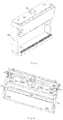
- Fig.4a and Fig.4b shows the configuration of the air supply duct 1061 near the air supply inlet 106 when a top panel 119 of the hood 101 is opened; as indicated by the arrows in Fig.4 , after being supplied downward vertically from the air supply inlet 106, the supply airflow is split below the air supply inlet 106 into two paths A and B by a flow-dividing sheet 1064, and flows to left and right sides of the hood; then, at a position near the left and right side walls of the hood, the supply airflow is split again into two paths, i.e., front and rear paths by the flow-dividing sheet 1062, that is, the left path airflow A is split by the flow-dividing sheet 1062 into a front path airflow A1 and a rear path airflow A2, and the right path airflow B is
- the air supply outlet 109 is provided with a mesh grille 116 covering the air supply outlet.
- the air supply outlet 110 is provided with a mesh grille 116 covering the air supply outlet, and a mesh screen covering the mesh grille is provided on the outside of the mesh grille 116, each screen hole of the mesh screen has a smaller area than each grille hole of the mesh grille.
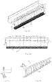
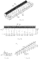
- each flow-guiding plate 1201 of the steady flow structures and all the sides of the central separator plates 1202 are seamlessly jointed to the air supply duct walls, as shown in Fig.6a , after flowing in from the left end of the steady flow structure 120 and the right end of the steady flow structure 121, the supply airflows A2 and B2 are respectively caught by the air catching plates 12011 of the flow-guiding plates in different heights into airflow paths 1065 constructed by corresponding flow-guiding plates and air supply duct walls; at the place where the directions of airflows are changed, the air catching plates 12011 are designed with arched surfaces for smoothly changing the directions of the airflows, preventing the formation of turbulent flows to the highest degree.
- Fig.6b and 6c are the front view and the left view of the structure near the second air supply outlet 110 respectively, the steady flow structures 120 and 121 are both provided with five flow-guiding plates 1201a-1201e with the heights gradually decreasing from 1201e to 1201a, thus, the supply airflows A2 and B2 are caught by the flow-guiding plates with different heights and are split into six branches as they flow towards the central separator plate 1202, the each six branches flow backwardly along the L-shape configuration of their corresponding flow-guiding plates.
- the supply airflows A2 and B2 are split by six airflow paths 1065 respectively, their flow rates are decreased and then most of the turbulent flows are corrected by the flow-guiding plates into uniform laminar flows, and redirected to the directions indicated by arrows shown in Fig. 6c by the arc-shaped air outlet guide plates 1203, which are provided orthogonally with the longitudinal plates of all the flow-guiding plates and inside of the air supply outlet 110, and blows obliquely and upwardly into the work chamber; the supply airflows in these directions effectively push the toxic gases located interiorly near the central portion of the work chamber.
- the mesh grille 116 and the mesh screen 117 arranged at the air supply outlet 110 further diffuse the supply airflows, thus to further ensure that uniform stable laminar airflows are supplied from the air supply outlet 110 to the work chamber.
- Fig.7 is a schematic view of the structure near the third air supply outlet 111.
- the supply airflows A11 and B11 flowing in from the left and right sides of the hood are split by the steady flow structures into multiple airflow paths after flowing through the two symmetrical steady flow structures 120 and 121, and finally, along the direction of the air outlet guide plate of the steady flow structure 120, blown out from the air supply outlet 111.
- each steady flow structure 120 and 121 comprises a plurality of flow-guiding plates 1201 formed in a substantial L-shape, each flow-guiding plate 1201 include an air catching plate 12011 which is one side of the L-shape and a longitudinal plate 12012 which is the other side of the L-shape; all the flow-guiding plates 1201 are arranged in a straight line, with the longitudinal plates 12012 of the flow-guiding plates being arranged in parallel with each other and all the air catching plates 12011 of the flow-guiding plates facing a same direction in which the airflow enters; ends of the longitudinal plates 12012 of all of the flow-guiding plates are aligned with each other, and lengths of the longitudinal plates are increased along the direction in which the airflow enters; both sides of all of the flow-guiding plates 1201 are seamlessly jointed to walls constructing the airflow duct so as to
- a central separator plate 1202 is provided between the aforementioned two steady flow structures 120 and 121, the central separator plate is placed at the center position of the aforementioned straight line, and in parallel with the longitudinal plates of all the flow-guiding plates, with each side of the central separator plate seamlessly jointed to the air supply duct walls such that the supply airflows entering into the steady flow structures from the left direction and from the right direction are separated from each other.
- all the flow-guiding plates 1201 of the two steady flow structures 120 and 121 and the central separator plate 1202 are arranged in a straight line with constant intervals, and the heights of all of the flow-guiding plates 1201 of the two steady flow structures 120 and 121 is increased with equal differences along the direction in which the airflows enter (from 1201a to 1201e).
- the steady flow structures 120 and 121 comprise two (commonly used) air outlet guide plates 1203 shaped as an arc, the air outlet guide plates are orthogonal to the longitudinal plates 12012 of all the flow-guiding plates, so as to change the directions of the airflows blown out from the air supply outlet.
- the air supply outlet 109 is provided with mesh grille 116 covering the air supply outlet.
- each flow-guiding plate 1201 of the steady flow structures and all the sides of the central separator plates 1202 are seamlessly jointed to the air supply duct walls, as shown in Fig.7a , after flowing in from the left end of the steady flow structure 120 and the right end of the steady flow structure 121, the supply airflows A11 and B11 are respectively caught by the air catching plates 12011 of the flow-guiding plates in different heights into airflow paths 1065 constructed by corresponding flow-guiding plates and air supply duct walls; at the place where the directions of airflows are changed, the air catching plates 12011 are designed with arched surfaces for smoothly changing the directions of the airflows, preventing the formation of turbulent flows to the highest degree.
- the airflow blowing out downwardly is located at the breathing-zone of hood operators, this will further reduce the risk of operators inhaling harmful substances, in addition, the airflow blowing out downwardly from the air supply outlet 111 forms an "Air curtain", which functions as a buffer between air inside of the work chamber 102 and outside of the hood, effectively preventing the risk of overflow.
- the mesh grille 116 arranged at the air supply outlet 111 further diffuse the supply airflows, thus to further ensure that uniform stable laminar airflows are supplied from the air supply outlet 111 to the work chamber.
- Fig. 8 shows the construction of the air exhaust duct 1071 of the ventilation apparatus 100 after a part of the side walls of the ventilation apparatus 100 is removed.
- the air exhaust duct 1071 is constituted by the hood and the three air baffles, wherein the lower air baffle 112 has a plurality of through holes 115 opened thereon, and the plurality of through holes 115 are distributed over the entire left-right width direction of the lower air baffle 112;
- the middle air baffle 113 is located above the lower air baffle 112, and is provided obliquely in the direction towards the rear wall 105 of the hood;
- the upper air baffle 114 is located above the middle air baffle 113, and is provided obliquely in a direction towards the upper wall of the hood; gaps are provided among the three air baffles, and between the three air baffles
- a plurality of horizontally extending exhaust gaps for exhausting is provided, so as to allow the airflow at different heights inside of the work chamber to quickly flow into the air exhaust duct 1071 and be exhausted without going through a long climbing path, thus exhaust power energy consumption is reduced;
- a plurality of gaps is applied to replace the large exhaust outlet region, and divides the airflow entering the air exhaust duct at multiple positions, which prevents the generation of turbulent flows, and stabalizes the exhaust airflow; in addition, since the exhaust gaps extend horizontally, the airflows in the work chamber are pushed by the supply airflow in a near horizontal form parallel to the surface; thereby establishing an effective push-pull airflow system.
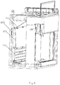
- the arrows in Fig.2 indicate how the air flows into, through and out of the hood of the ventilation apparatus.
- the supply airflow enters the air supply duct 1061 from the air supply inlet 106, and flows to each of the air supply outlets 109, 110 and 111, and enters into the work chamber 102 along the direction indicated by the arrows; meanwhile, a portion of environment air also enters into the work chamber 102 from the front opening at an angle perpendicular to the front opening.
- the air will be pushed and pulled evenly by supply airflow and exhaust airflow towards the air exhaust duct 1071, and then be exhausted from the air exhaust outlet 107 at the top of the hood along the direction indicated by the arrows.
- the work chamber 102 comprises an inclined top wall 118 inclining from the first air supply outlet 109 toward the upmost exhaust gap, wherein both sides of the inclined top wall 118 are jointed to the left and right side walls 103,104 of the hood, the bottom end thereof is jointed to the upper edge of the first air supply outlet 109, and the top end thereof is jointed to the top wall. Due to exhaust devices operating with high air exhaust amounts, in conventional fume hoods, vortexes are usually formed at the inner top portion of the work chamber, thus the toxic and harmful gases are unable to be exhausted.
- the design of the inclined top wall 118 can prevent the vortex from expanding, and in conjunction with the laminar airflows supplied out from the first air supply outlet 109 at the inner top of the work chamber 102, enables the airflow within the hood to ascend towards the air exhaust region slowly and evenly along the inclined wall.
- the angle and shape of the inclined top wall 118 are designed to help control and prevent the overflow of harmful substances in the air inside of the work chamber 102, and to reduce the likelihood of vortex formations at the top of the work chamber 102.
- the inclined top wall can also be integrated with a flat-panel work light for illuminating the work chamber, which exempts the need to set up work light in other locations of the work chamber, and is simple and elegant.
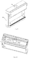
- the ventilation apparatus provided with two of the steady flow structures which are arranged symmetrically in left and right is described hereinbefore, it is known to those skilled in the art that the present invention may also provide a ventilation apparatus that is merely provided with one steady flow structure at each air supply outlet based on the substance thereof, Fig.9 shows a schematic view of an exterior structure of the air supply duct in this kind of ventilation apparatus.
- Fig.10 shows the configuration of the air supply duct 1061 near the air supply inlet 106 when a top panel 119 of the hood 101 is opened; as indicated by the arrows in Fig.10 , after being supplied downward vertically from the air supply inlet 106, the supply airflow is split below the air supply inlet 106 into two paths A and B, and flows to left and right sides of the hood; after being redirected by the side walls, the airflow in path A is connected with the third air supply outlet directly, and blows from left side of the hood rightward into the steady flow structure inside the third air supply outlet; and the right path airflow B is split again into two paths, i.e., a front path Bland a rear path B2, by the flow-dividing sheet 1062 at the position near the right side wall of the hood; the front path airflow
- the steady flow structure 120 comprises two air outlet guide plates 1203 shaped as an arc, the air outlet guide plates are orthogonal to the longitudinal plates 12012 of all the flow-guiding plates, so as to change directions from which the airflows blown out from the air supply outlet.
- each flow-guiding plate 1201 of the steady flow structure Since both sides of each flow-guiding plate 1201 of the steady flow structure are seamlessly jointed to the air supply duct walls, as shown in Fig.11a , after flowing in from the right end of the steady flow structure 120, the supply airflows A12 and B12 are respectively caught by the air catching plates 12011 of the flow-guiding plates in different heights into airflow paths 1065 constructed by corresponding flow-guiding plates and air supply duct walls; at the place where the directions of airflows are changed, the air catching plates 12011 are designed with arched surfaces for smoothly changing the directions of the airflows, preventing the formation of turbulent flows to the highest degree.
- Fig.11b and 11c are the front view and the left view of the structure near the first air supply outlet 109 respectively
- the steady flow structure 120 is provided with eleven flow-guiding plates 1201a-1201k with the heights gradually increasing from 1201a to 1201k, thus, the supply airflow B12 is caught by the flow-guiding plates with different heights and are split into twelve branches as they flow towards the central separator plate 1202, the twelve branches flow downwardly along the L-shape configuration of corresponding flow-guiding plates.
- the supply airflow B12 is split by twelve airflow paths 1065 respectively, their flow rates are decreased and then most of the turbulent flows are corrected by the flow-guiding plates into uniform laminar flows, and redirected to the directions indicated by arrows shown in Fig.
- each of the two air supply outlets is provided with one steady flow structure 120 inside the air supply outlets before the supply airflow blows out from the air supply outlets, and as the directions in which the supply airflows blow are different, the steady flow structure within each air supply outset is set up differently.
Landscapes
- Engineering & Computer Science (AREA)
- Chemical & Material Sciences (AREA)
- Combustion & Propulsion (AREA)
- Mechanical Engineering (AREA)
- General Engineering & Computer Science (AREA)
- Air-Flow Control Members (AREA)
- Ventilation (AREA)
- Duct Arrangements (AREA)
Applications Claiming Priority (2)
| Application Number | Priority Date | Filing Date | Title |
|---|---|---|---|
| CN201610152404.1A CN107202415B (zh) | 2016-03-17 | 2016-03-17 | 一种稳流结构及应用该稳流结构的通风设备 |
| PCT/CN2016/078290 WO2017156802A1 (fr) | 2016-03-17 | 2016-04-01 | Structure de stabilisation d'écoulement et dispositif de ventilation utilisant celui-ci |
Publications (2)
| Publication Number | Publication Date |
|---|---|
| EP3431894A1 true EP3431894A1 (fr) | 2019-01-23 |
| EP3431894A4 EP3431894A4 (fr) | 2019-11-06 |
Family
ID=59850810
Family Applications (1)
| Application Number | Title | Priority Date | Filing Date |
|---|---|---|---|
| EP16884243.3A Withdrawn EP3431894A4 (fr) | 2016-03-17 | 2016-04-01 | Structure de stabilisation d'écoulement et dispositif de ventilation utilisant celui-ci |
Country Status (8)
| Country | Link |
|---|---|
| US (1) | US10357810B2 (fr) |
| EP (1) | EP3431894A4 (fr) |
| JP (1) | JP2019508651A (fr) |
| KR (1) | KR20180051650A (fr) |
| CN (1) | CN107202415B (fr) |
| CA (1) | CA2976217A1 (fr) |
| SG (1) | SG11201705777SA (fr) |
| WO (1) | WO2017156802A1 (fr) |
Cited By (1)
| Publication number | Priority date | Publication date | Assignee | Title |
|---|---|---|---|---|
| CN112588680A (zh) * | 2020-12-16 | 2021-04-02 | 无锡先导智能装备股份有限公司 | 清洗装置及清洗设备 |
Families Citing this family (41)
| Publication number | Priority date | Publication date | Assignee | Title |
|---|---|---|---|---|
| CN107497815B (zh) * | 2017-10-11 | 2020-08-07 | 倚世节能科技(上海)有限公司 | 通风柜 |
| DE102017129479A1 (de) * | 2017-12-11 | 2019-06-13 | Trumpf Laser- Und Systemtechnik Gmbh | Laserbearbeitungsvorrichtung zum Bearbeiten von Werkstücken mittels Laser |
| JP6893481B2 (ja) * | 2018-01-24 | 2021-06-23 | 株式会社豊田自動織機 | レジスタ |
| CN108213020A (zh) * | 2018-03-21 | 2018-06-29 | 苏州特福佳实验室系统工程有限公司 | 内补风节能通风柜 |
| CN110125131A (zh) * | 2019-05-24 | 2019-08-16 | 广东天赐湾实验室装备制造有限公司 | 一种应用于实验室的双补风式空气循环系统 |
| JP7182523B2 (ja) * | 2019-07-10 | 2022-12-02 | 株式会社日立産機システム | 安全キャビネット |
| EP3771491A1 (fr) * | 2019-07-30 | 2021-02-03 | Burdinola S. Coop. | Chambre de protection |
| CN111059677A (zh) * | 2019-11-26 | 2020-04-24 | 广州柯美隆实验设备科技有限公司 | 一种可调节增速稳流型节能理化安全柜 |
| CN111112271A (zh) * | 2019-11-26 | 2020-05-08 | 广州柯美隆实验设备科技有限公司 | 一种可调增速稳流型理化安全柜 |
| CN110749078B (zh) * | 2019-11-29 | 2023-09-26 | 广东美的制冷设备有限公司 | 导风板组件和空调器 |
| CN111121261B (zh) * | 2019-11-29 | 2023-09-12 | 广东美的制冷设备有限公司 | 导风板组件和空调器 |
| CN111076396B (zh) * | 2019-11-29 | 2023-09-12 | 广东美的制冷设备有限公司 | 导风板组件和空调器 |
| CN111006382B (zh) * | 2019-11-29 | 2023-10-31 | 广东美的制冷设备有限公司 | 导风板组件和空调器 |
| CN110749079B (zh) * | 2019-11-29 | 2023-09-08 | 广东美的制冷设备有限公司 | 导风板组件和空调器 |
| CN111351200B (zh) * | 2019-11-29 | 2023-09-26 | 广东美的制冷设备有限公司 | 导风板组件和空调器 |
| CN110762822B (zh) * | 2019-11-29 | 2023-10-31 | 广东美的制冷设备有限公司 | 导风板组件和空调器 |
| CN111006381B (zh) * | 2019-11-29 | 2023-09-26 | 广东美的制冷设备有限公司 | 导风板组件和空调器 |
| CN111156680B (zh) * | 2019-11-29 | 2023-09-12 | 广东美的制冷设备有限公司 | 导风板组件和空调器 |
| CN111185455B (zh) * | 2020-01-14 | 2025-01-28 | 江苏科仕达实验室环保科技有限公司 | 一种节能型补风通风柜 |
| CN111195637B (zh) * | 2020-03-10 | 2021-03-16 | 雷柏特(南通)实验室系统工程有限公司 | 一种新型内补风排风柜 |
| CN111346891B (zh) * | 2020-03-17 | 2025-04-08 | 珠海科艺普实验装备有限公司 | 一种通风柜 |
| CN111336641B (zh) * | 2020-03-18 | 2021-04-06 | 广州市鑫湖能源科技有限公司 | 一种风帘器 |
| CN111351138B (zh) * | 2020-03-26 | 2025-08-19 | 青岛海尔空调器有限总公司 | 空调器 |
| CN112453001A (zh) * | 2020-10-27 | 2021-03-09 | 苏州薪火云智能科技有限公司 | 一种节能稳流通风柜 |
| CN112439472A (zh) * | 2020-11-26 | 2021-03-05 | 重庆劲旗科技股份有限公司 | 气帘式防护实验台 |
| CN112827993B (zh) * | 2021-01-29 | 2025-05-02 | 广东天赐湾实验室装备制造有限公司 | 配备有过风开口的通风柜 |
| CN112827992B (zh) * | 2021-01-29 | 2025-05-02 | 广东天赐湾实验室装备制造有限公司 | 侧过风式通风柜 |
| CN112710054B (zh) * | 2021-01-29 | 2025-01-03 | 广东天赐湾实验室装备制造有限公司 | 能强制向下送风的通风柜 |
| CN113414209B (zh) * | 2021-07-19 | 2024-06-14 | 青岛中科汉维实验室装备科技有限公司 | 一种补风型实验室通风柜 |
| CN113385513A (zh) * | 2021-07-21 | 2021-09-14 | 青岛中科汉维实验室装备科技有限公司 | 一种补风型通风柜 |
| CN113385514A (zh) * | 2021-07-21 | 2021-09-14 | 青岛中科汉维实验室装备科技有限公司 | 一种补风型排风柜 |
| CN113843246A (zh) * | 2021-10-09 | 2021-12-28 | 广东天赐湾实验室装备制造有限公司 | 适于整流的风箱及通风柜 |
| CN114085934B (zh) * | 2021-11-10 | 2022-10-28 | 北京中冶设备研究设计总院有限公司 | 上排风干法粒化装置 |
| EP4248805A1 (fr) | 2022-03-23 | 2023-09-27 | Carrier Corporation | Meuble présentoir réfrigéré et procédé de dispersion d'accumulation de gaz réfrigérant |
| CN114484674B (zh) * | 2022-03-29 | 2024-04-09 | 贵州腾翔通风设备安装有限公司 | 通风管道均匀出风装置 |
| CN115007590B (zh) * | 2022-06-17 | 2023-11-10 | 倚世节能科技(上海)有限公司 | 一种通风柜 |
| CN116422670A (zh) * | 2023-03-27 | 2023-07-14 | 上海亚保实验室系统工程有限公司 | 一种实验室多通道导流风道及优化该导流风道结构的方法 |
| IT202300018201A1 (it) * | 2023-09-05 | 2025-03-05 | Mopec Europe Srl | Sistema di velo d'aria protettivo da sostanze nocive applicato alle grossing station e/o banchi di riduzione istopatologica |
| CN117206300B (zh) * | 2023-10-31 | 2025-08-19 | 苏州博思普工程技术有限公司 | 一种用于通风柜的补风送风自由切换的装置 |
| KR102806619B1 (ko) * | 2024-05-30 | 2025-05-16 | 주식회사 아카 | 실내 음압 개선 및 에너지 절감형 급배기 일체형 시스템 흄후드 |
| KR102836296B1 (ko) * | 2024-11-28 | 2025-07-22 | 김영훈 | 배기 후드 장치 |
Family Cites Families (37)
| Publication number | Priority date | Publication date | Assignee | Title |
|---|---|---|---|---|
| US2627220A (en) * | 1950-11-04 | 1953-02-03 | Sheldon & Co E H | Fume hood |
| US2819666A (en) * | 1955-12-14 | 1958-01-14 | Kirk & Blum Mfg Company | Laboratory fume hood |
| US3279883A (en) * | 1962-12-20 | 1966-10-18 | Midland Ross Corp | Distributing purified air |
| US3251177A (en) * | 1963-05-15 | 1966-05-17 | Arthur K Baker | Dust-free bench |
| US3318227A (en) * | 1965-03-10 | 1967-05-09 | Kewaunee Mfg Company | Fume hood |
| US3604333A (en) * | 1969-11-05 | 1971-09-14 | Kewaunee Scient Equipment Corp | Fume hood |
| US3771323A (en) * | 1972-05-17 | 1973-11-13 | Dualjet Corp | Refrigerated reach-in display compartment |
| US3897721A (en) * | 1973-04-09 | 1975-08-05 | Rochelle Corp | Fumehood with compensating air supply |
| US4177717A (en) * | 1978-07-27 | 1979-12-11 | American Hospital Supply Corporation | Baffle system for fume hood |
| US4434711A (en) * | 1980-12-24 | 1984-03-06 | Hamilton Industries, Inc. | Fume hood with damper controlled baffles and method |
| JPS60101441A (ja) * | 1983-11-07 | 1985-06-05 | Michihiko Kawano | 流体の流出入装置 |
| JPS62228831A (ja) * | 1986-03-31 | 1987-10-07 | Kojima Press Co Ltd | 空調用ダクトの空気流偏向装置 |
| JPS62228832A (ja) * | 1986-03-31 | 1987-10-07 | Kojima Press Co Ltd | 空調用ダクトの空気流偏向装置 |
| US4785722A (en) * | 1987-07-28 | 1988-11-22 | Hamilton Industries | Fume hood with step baffles |
| JPH02109946U (fr) * | 1989-02-17 | 1990-09-03 | ||
| JPH04113183A (ja) * | 1990-09-04 | 1992-04-14 | Sanyo Electric Co Ltd | オープンショーケースの運転方法 |
| US5334089A (en) * | 1992-09-18 | 1994-08-02 | Fisher Hamilton Scientific Inc. | Fume hood with adjustable baffle assembly |
| JP2870378B2 (ja) * | 1993-10-15 | 1999-03-17 | 三菱電機株式会社 | 送風装置 |
| JP2706222B2 (ja) * | 1994-02-10 | 1998-01-28 | 通彦 川野 | 案内羽根入りエルボ |
| US5675983A (en) * | 1996-09-11 | 1997-10-14 | Kysor Industrial Corporation | Synergistic refrigerated display case |
| JP2948199B2 (ja) * | 1997-09-22 | 1999-09-13 | 通彦 川野 | 案内羽根入り吸込エルボ |
| US6428408B1 (en) * | 2000-05-18 | 2002-08-06 | The Regents Of The University Of California | Low flow fume hood |
| US6659857B2 (en) * | 2001-07-11 | 2003-12-09 | Flow Sciences, Inc. | Turbulence-free laboratory safety enclosure |
| US7531017B2 (en) * | 2003-07-28 | 2009-05-12 | Flow Sciences, Inc. | Lateral-flow biohazard safety enclosure |
| KR100613765B1 (ko) * | 2005-08-22 | 2006-08-22 | 수공테크 주식회사 | 청정실용 팬구조물 |
| JP2008030516A (ja) * | 2006-07-26 | 2008-02-14 | Howa Kasei Kk | 空気吹出調整用レジスタ |
| JP2008134030A (ja) * | 2006-11-29 | 2008-06-12 | Fuji Electric Retail Systems Co Ltd | ライン型吹出口装置 |
| US20080153409A1 (en) * | 2006-12-21 | 2008-06-26 | Edward Neal Koop | Static air mixer |
| KR100904564B1 (ko) * | 2007-08-13 | 2009-06-25 | 지종민 | 도우컨디셔너의 습열분배구조 |
| JP4884547B2 (ja) * | 2010-04-04 | 2012-02-29 | 有限会社川野技研 | 案内羽根入り吹出エルボ |
| CN201865683U (zh) * | 2010-08-16 | 2011-06-15 | 彭世雄 | 片式栅栏分割导流消声器 |
| US9056339B2 (en) * | 2010-08-27 | 2015-06-16 | Exposure Control Technologies, Inc. | Airfoil and baffle assemblies that reduce airflow requirements for fume hoods and fume hoods incorporating same |
| JP6003756B2 (ja) * | 2013-03-26 | 2016-10-05 | 富士ゼロックス株式会社 | 送風装置及び画像形成装置 |
| CN204710833U (zh) * | 2015-04-10 | 2015-10-21 | 阮红正 | 通风柜 |
| CN204934175U (zh) * | 2015-07-01 | 2016-01-06 | 岳彬 | 一种通风柜通风系统 |
| JP5881227B1 (ja) * | 2015-08-07 | 2016-03-09 | 有限会社川野技研 | エアカーテン装置 |
| CN205536442U (zh) * | 2016-03-17 | 2016-08-31 | 阮红正 | 一种稳流结构及应用该稳流结构的通风设备 |
-
2016
- 2016-03-17 CN CN201610152404.1A patent/CN107202415B/zh active Active
- 2016-04-01 WO PCT/CN2016/078290 patent/WO2017156802A1/fr not_active Ceased
- 2016-04-01 SG SG11201705777SA patent/SG11201705777SA/en unknown
- 2016-04-01 EP EP16884243.3A patent/EP3431894A4/fr not_active Withdrawn
- 2016-04-01 KR KR1020187012367A patent/KR20180051650A/ko not_active Ceased
- 2016-04-01 CA CA2976217A patent/CA2976217A1/fr not_active Abandoned
- 2016-04-01 US US15/549,643 patent/US10357810B2/en active Active
- 2016-04-01 JP JP2017544760A patent/JP2019508651A/ja active Pending
Cited By (1)
| Publication number | Priority date | Publication date | Assignee | Title |
|---|---|---|---|---|
| CN112588680A (zh) * | 2020-12-16 | 2021-04-02 | 无锡先导智能装备股份有限公司 | 清洗装置及清洗设备 |
Also Published As
| Publication number | Publication date |
|---|---|
| JP2019508651A (ja) | 2019-03-28 |
| SG11201705777SA (en) | 2017-10-30 |
| US10357810B2 (en) | 2019-07-23 |
| WO2017156802A1 (fr) | 2017-09-21 |
| US20180065161A1 (en) | 2018-03-08 |
| CN107202415B (zh) | 2019-07-19 |
| CN107202415A (zh) | 2017-09-26 |
| CA2976217A1 (fr) | 2017-09-17 |
| KR20180051650A (ko) | 2018-05-16 |
| EP3431894A4 (fr) | 2019-11-06 |
Similar Documents
| Publication | Publication Date | Title |
|---|---|---|
| US10357810B2 (en) | Steady flow structure and a ventilation apparatus having said steady flow structure | |
| CN205536442U (zh) | 一种稳流结构及应用该稳流结构的通风设备 | |
| CN204710833U (zh) | 通风柜 | |
| US6428408B1 (en) | Low flow fume hood | |
| CN108435747A (zh) | 通风柜 | |
| US20060154590A1 (en) | Method and device for local ventilation by buiding airflow and separating airflow | |
| JP4870307B2 (ja) | エアカーテンを備える排気フード | |
| CN115007590B (zh) | 一种通风柜 | |
| CN102037286A (zh) | 用于增强捕获和封锁能力的排气装置、系统和方法 | |
| EP0199762A1 (fr) | Appareil et procede de ventilation de chambres. | |
| JP6184190B2 (ja) | 低温吹出口装置 | |
| JPWO2019111451A1 (ja) | プッシュフード | |
| JP5214584B2 (ja) | 一様流吹き出しプッシュフード | |
| JP2019078422A (ja) | 空調システム | |
| CN217857912U (zh) | 一种通风柜 | |
| CN207196802U (zh) | 一种通风设备 | |
| JP5009859B2 (ja) | 開放式プッシュプル型換気装置 | |
| JP2013181715A (ja) | 空調システムおよび空調方法 | |
| JP5830730B2 (ja) | プッシュプル型換気装置 | |
| JP4551984B2 (ja) | 卓上型換気装置 | |
| JP7232462B2 (ja) | 吹出口装置 | |
| CN115247852B (zh) | 厂房空间散热结构 | |
| CN219648342U (zh) | 一种排风柜 | |
| JP2020076563A (ja) | ユニット型クリーンルーム及びユニット型クリーンルーム施設方法 | |
| JP4281957B2 (ja) | プッシュプル型換気装置 |
Legal Events
| Date | Code | Title | Description |
|---|---|---|---|
| STAA | Information on the status of an ep patent application or granted ep patent |
Free format text: STATUS: UNKNOWN |
|
| STAA | Information on the status of an ep patent application or granted ep patent |
Free format text: STATUS: THE INTERNATIONAL PUBLICATION HAS BEEN MADE |
|
| PUAI | Public reference made under article 153(3) epc to a published international application that has entered the european phase |
Free format text: ORIGINAL CODE: 0009012 |
|
| STAA | Information on the status of an ep patent application or granted ep patent |
Free format text: STATUS: REQUEST FOR EXAMINATION WAS MADE |
|
| 17P | Request for examination filed |
Effective date: 20170718 |
|
| AK | Designated contracting states |
Kind code of ref document: A1 Designated state(s): AL AT BE BG CH CY CZ DE DK EE ES FI FR GB GR HR HU IE IS IT LI LT LU LV MC MK MT NL NO PL PT RO RS SE SI SK SM TR |
|
| AX | Request for extension of the european patent |
Extension state: BA ME |
|
| DAV | Request for validation of the european patent (deleted) | ||
| DAX | Request for extension of the european patent (deleted) | ||
| A4 | Supplementary search report drawn up and despatched |
Effective date: 20191004 |
|
| RIC1 | Information provided on ipc code assigned before grant |
Ipc: F24F 3/16 20060101ALI20190927BHEP Ipc: F15D 1/14 20060101ALI20190927BHEP Ipc: F24F 13/20 20060101ALI20190927BHEP Ipc: F15D 1/04 20060101ALI20190927BHEP Ipc: F24F 13/08 20060101AFI20190927BHEP Ipc: B08B 15/02 20060101ALI20190927BHEP Ipc: F24F 7/06 20060101ALI20190927BHEP |
|
| STAA | Information on the status of an ep patent application or granted ep patent |
Free format text: STATUS: THE APPLICATION IS DEEMED TO BE WITHDRAWN |
|
| 18D | Application deemed to be withdrawn |
Effective date: 20200603 |