EP3431982A1 - Mikroausleger - Google Patents
Mikroausleger Download PDFInfo
- Publication number
- EP3431982A1 EP3431982A1 EP18000307.1A EP18000307A EP3431982A1 EP 3431982 A1 EP3431982 A1 EP 3431982A1 EP 18000307 A EP18000307 A EP 18000307A EP 3431982 A1 EP3431982 A1 EP 3431982A1
- Authority
- EP
- European Patent Office
- Prior art keywords
- cantilever
- platform
- microcantilever
- measuring device
- biological system
- Prior art date
- Legal status (The legal status is an assumption and is not a legal conclusion. Google has not performed a legal analysis and makes no representation as to the accuracy of the status listed.)
- Withdrawn
Links
Images

Classifications
-
- G—PHYSICS
- G01—MEASURING; TESTING
- G01N—INVESTIGATING OR ANALYSING MATERIALS BY DETERMINING THEIR CHEMICAL OR PHYSICAL PROPERTIES
- G01N29/00—Investigating or analysing materials by the use of ultrasonic, sonic or infrasonic waves; Visualisation of the interior of objects by transmitting ultrasonic or sonic waves through the object
- G01N29/02—Analysing fluids
- G01N29/022—Fluid sensors based on microsensors, e.g. quartz crystal-microbalance [QCM], surface acoustic wave [SAW] devices, tuning forks, cantilevers, flexural plate wave [FPW] devices
-
- G—PHYSICS
- G01—MEASURING; TESTING
- G01N—INVESTIGATING OR ANALYSING MATERIALS BY DETERMINING THEIR CHEMICAL OR PHYSICAL PROPERTIES
- G01N29/00—Investigating or analysing materials by the use of ultrasonic, sonic or infrasonic waves; Visualisation of the interior of objects by transmitting ultrasonic or sonic waves through the object
- G01N29/02—Analysing fluids
- G01N29/036—Analysing fluids by measuring frequency or resonance of acoustic waves
-
- G—PHYSICS
- G01—MEASURING; TESTING
- G01N—INVESTIGATING OR ANALYSING MATERIALS BY DETERMINING THEIR CHEMICAL OR PHYSICAL PROPERTIES
- G01N2291/00—Indexing codes associated with group G01N29/00
- G01N2291/01—Indexing codes associated with the measuring variable
- G01N2291/014—Resonance or resonant frequency
-
- G—PHYSICS
- G01—MEASURING; TESTING
- G01N—INVESTIGATING OR ANALYSING MATERIALS BY DETERMINING THEIR CHEMICAL OR PHYSICAL PROPERTIES
- G01N2291/00—Indexing codes associated with group G01N29/00
- G01N2291/02—Indexing codes associated with the analysed material
- G01N2291/025—Change of phase or condition
- G01N2291/0255—(Bio)chemical reactions, e.g. on biosensors
-
- G—PHYSICS
- G01—MEASURING; TESTING
- G01N—INVESTIGATING OR ANALYSING MATERIALS BY DETERMINING THEIR CHEMICAL OR PHYSICAL PROPERTIES
- G01N2291/00—Indexing codes associated with group G01N29/00
- G01N2291/02—Indexing codes associated with the analysed material
- G01N2291/025—Change of phase or condition
- G01N2291/0256—Adsorption, desorption, surface mass change, e.g. on biosensors
- G01N2291/0257—Adsorption, desorption, surface mass change, e.g. on biosensors with a layer containing at least one organic compound
-
- G—PHYSICS
- G01—MEASURING; TESTING
- G01N—INVESTIGATING OR ANALYSING MATERIALS BY DETERMINING THEIR CHEMICAL OR PHYSICAL PROPERTIES
- G01N2291/00—Indexing codes associated with group G01N29/00
- G01N2291/04—Wave modes and trajectories
- G01N2291/042—Wave modes
- G01N2291/0427—Flexural waves, plate waves, e.g. Lamb waves, tuning fork, cantilever
Definitions
- the invention relates to a microcantilever, a measuring device and a method for determining mass and/or mechanical properties of a biological system.
- Cantilevers and measuring devices as well as methods for determining mass and/or mechanical properties of biological systems are known from the state of the art.
- Micro cantilevers which are microresonators with both at least a fixed and a free end (for instance triangular cantilevers have two fixed ends) can be used to determine the mass of objects attached to them, since their natural resonance frequency is a function of the mass.
- cantilevers immersed in liquids can be used to track over time the total mass of cells in culture conditions.
- the mass sensitivity of a cantilever depends on the position in which the mass is located.
- Micro cantilevers known from the state of the art consist of one straight beam. In the case of living cells, the position of the cell on the cantilever can change over time since some cells are able to migrate. Consequently, the cell position must be tracked in order to accurately determine its mass.
- the cantilever mass sensitivity at a certain position of the cantilever is proportional to the square of the oscillation amplitude at that position. Therefore, in particular the mass sensitivity of rectangular cantilevers vibrating at the fundamental mode, which is defined by the lowest natural resonance frequency, is maximum at the free and zero at the fixed end. This can lead to a massive inaccuracy depending on cell position.
- a solution to this technical problem is achieved by providing a microcantilever in particular for a measuring device for determining mass and/or mechanical properties of a biological system wherein the cantilever has a barrier preventing migration of the biological system.
- the barrier of the microcantilever provides a cantilever section to host a biological sample, a living cell, for example, so that its mass is determined accurately, with or without tracking its position over time. In other words, the need of position tracking of the biological system for accurate determination of its mass is avoided or at least minimized.
- the barrier can be a physical, geometrical restriction on the cantilever, like specific geometries that use narrow necks over which a biological system like a cell does not like to migrate.
- the geometrical restriction can be provided as a gap or a hole in the cantilever beam.
- the gap divides the cantilever in two sections or pieces: one section where the biological system is provided, e.g. cells, and another section free of the biological system. Therefore, the mass of the biological systems can be determined effectively.
- the size of the section providing the biological system can be minimized according to size of the biological system, if required. In some examples, where the section is provided such that position correction is no longer needed, this section might be enlarged.
- the geometrical restriction on the cantilever can be provided by a connector connecting the two sections or pieces of the cantilever beam.
- a cantilever beam having a triangular shape where the section free of the biological system is an empty space within the triangular shape and/or the beams holding the section to host the biological system, provides effective boundaries to restric the possible locations of the biological system and accurately determine its mass.
- the beams can be chosen for instance very narrow or with special physical or chemical properties so that migration of the biological system through them is avoided.
- a barrier can also be achieved by a functional barrier.
- a part of the cantilever is functionalized to adhere and/or repel to a biological system.
- Functionalization of the cantilever can mean that it is physically or chemically modified in order to exhibit different physical, chemical or biological properties.
- the functionalization can have different applications, for instance to attach the biological sample to the cantilever or to induce a special behavior of the sample.
- chemical functionalization of the cantilever also other methods to adhere the biological system to the cantilever are possible.
- a micro-channeled cantilever can be used that adheres the biological system to the cantilever by means of a suction mechanism.
- the attachment between the sample and the cantilever can also be achieved by using magnetic or electric interactions mediated by magnetic coatings, electrical fields or for instance creating a Lorentz force by driving current through the cantilever while being subjected to magnetic fields.
- specific functionalization will not be necessary, if the sample attaches to the cantilever without specific binding means because of already existing physical or chemical interactions between the sample and the cantilever.
- a barrier can also be achieved by a platform linked to the cantilever.
- the one or more edges of the platform build a respective barrier.
- the whole platform can be oscillated with a certain amplitude.
- samples attaching to the platform can freely move on the platform with a constant cantilever mass sensitivity.
- Living cells or any other sample can be attached on the platform.
- the platform can preferably, but not limited to, be linked to the free end of the cantilever or nearby, however other locations are possible as well.
- a platform linked to or near the free end of the cantilever beam can be favorable, in particular for rectangular cantilevers, vibrating at the fundamental mode, which is defined by the lowest natural resonance frequency, since it provides maximum mass sensitivity.
- the platform can be preferably perpendicular or parallel to the cantilever beam.
- the platform is preferably linked to a small portion of the cantilever (cf. Figure 2 ). This has the advantage that by construction the whole platform is moving essentially with the same oscillation amplitude. Therefore, the mass of any sample attached on the platform can be accurately determined without the need of tracking and accounting for possible sample displacements within the platform. Furthermore, by use of physical or chemical modifications, like edges of the platform or coatings, samples are confined to stay within the platform, being very unlikely that migrating samples such as some mammalian cells, move out from the platform.
- the platform can define a T or L shaped cantilever. This means that the perpendicular platform can be attached at one side or at the middle to the cantilever beam. Also, other geometries can be used (cf. Figure 2 ).
- the platform can be preferably linked near an antinode of the cantilever or preferably linked to an antinode of the cantilever beam.
- the antinodes of the cantilever are points with the highest oscillation amplitude for a certain eigenmode and therefore provide the highest mass sensitivity.
- the number and location of antinodes depends on the vibration eigenmode of the cantilever and the cantilever geometry.
- the cantilever can be oscillated with several eigenmodes simultaneously. Having the platform linked near or to an antinode, the whole platform moves with the amplitude of the antinode.
- the cantilever beam can be provided with more than one platform.
- Each platform can be preferably linked to or near an antinode. Therefore, as example, it could be possible to have a cantilever that has a platform located at the antinode of the fundamental eigenmode and a second platform located at one antinode of the fourth eigenmode of the cantilever beam.
- the platforms may have any orientation relative to the cantilever beam.
- the microcantilever is compatible with state of the art optical microscopies.
- a second aspect of the invention relates to a measuring device in particular for determining mass and/or mechanical properties of a biological system with a microcantilever according to the invention wherein the measuring device is a scanning probe microcope, atomic force microscope (AFM), cytomass device (cf. Figure 4 ), microfluidic system or a micro chamber.
- the measuring device is a scanning probe microcope, atomic force microscope (AFM), cytomass device (cf. Figure 4 ), microfluidic system or a micro chamber.
- the measuring device can be combined with state of the art optical microscopes such as fluorescence microscopy, confocal microscopy, differential interference contrast, phase contrast, etc.
- the cantilever and/or platform or at least part of it is partially transparent for at least a wavelength within the visual spectrum. This has the advantage that, regardless orientation within the measuring device, transmitted light microscopy techniques can be used simultaneously with the mass and/or mechanical measurement of the biological system. However transmitted light microscopy techniques can still be used even if the cantilever and/or platform is not transparent by orienting the device such that light goes through the sample (for instance Figure 4 ).
- optical information from the sample can be obtained by modifying the pathway of light with the help of mirrors as for instance mounting the cantilever on a side-view cantilever holder.
- optical information can be obtained by using fluorescence microscopy and/or reflective light microscopy techniques.
- the cantilever and/or platform can be fully or partially coated with metallic layers, piezoresistive layers, piezo electric layers, etc. This has the advantage of improving the signal of reflected light microscopy techniques and/or improving the excitation and/or detection of the cantilever movement. Additionally, this has the advantage of applying to and/or reading electric signals from the sample. Electrical signals can be applied to and/or read from the sample as well by using micro-channeled cantilevers, such that mass and/or mechanical measurements together with electrical measurements of the biological sample can be obtain simultaneously.
- the cantilever can be immersed in a buffer solution. This allows detecting the total mass of a biological sample under physiological conditions.
- the cantilever can be fully or partially immersed in a buffer solution.
- the cantilever can be surrounded by a diving bell ( Figure 2b ).
- a diving bell Figure 2b .
- the mass resolution of a cantilever mass measurement can be incremented by increasing the oscillation amplitude of the platform since the phase noise is then reduced.
- mass measurements are preferably performed by exciting a movement of the cantilever rather than using the cantilever movement due to the thermal noise.
- the cantilever movement can be excited by using an intensity modulated light source, magnetically, electrically, thermally and/or mechanically induced.
- the cantilever can be self-actuated for instance by containing piezoelectric elements and/or resistors that can be driven to induce a cantilever oscillation.
- the cantilever can be a self-sensing cantilever for instance by integrating piezoresistors and/or piezoelectric elements to detect the cantilever deflection.
- the cantilever movement can be read out by an optical beam deflection scheme, a Doppler interferometer, etc.
- a third inventive aspect of the invention relates to a method for determining mass and/or mechanical properties of a biological system with a microcantilever according to the invention and/or a measuring device according to the invention.
- the method can also comprise exciting the microcantilever with one or more vibrational modes.
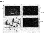
- Fig. 1 shows a position insensitive L-shaped microcantilever 1 in various images Figure 1a, 1b and 1d , and a schematic drawing of the cantilever in Figure 1c .
- Figure 1a shows a scanning electron microscopy (SEM) image of a perspective of a L-shaped microcantilever and Figure 1b shows a side view of a L-shaped microcantilever, sculpted with a focused ion beam (FIB).
- Figure 1d depicts an optical microscopy image showing the top view of the L-shaped cantilever of Figures 1a and 1b .
- a cell 3 attached to the cantilever 1.
- FIG 1c a schematic picture of a cell 3 attached to a plate 2 of the L-shaped microcantilever 1 is shown.
- the cantilever 1 is moved laterally towards the cell 3 in order to attach the cell 3 to the functionalized plate 2. After this, the cantilever 1 is withdrawn from the surface of the Petri dish to measure the mass of the cell 3 over time.
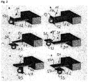
- Figure 2a shows a cantilever 11 with a platform 12 attached at the free end of the cantilever 11, perpendicular to the cantilever beam 14.
- a cell 13 is attached to the platform 12.
- the platform 12 is linked to the of the cantilever 11.
- the whole platform 12 is moving essentially with the same oscillation amplitude as the cantilever 11. Therefore, the mass of the cell 13 attached on the platform 12 can be accurately determined.
- the platform defines a T shaped cantilever in Fig. 2a, 2b .
- the platform 12 defines a L shaped cantilever. This means that the perpendicular platform can be attached at one side or at the middle to the cantilever beam.
- cantilever of Fig. 2a is equipped with a diving bell 15.
- the cantilever 11 body can thus be partially kept out of a buffer solution, for example, which increases the quality factor of the cantilever 11 and therefore the mass sensitivity.
- Figure 2c shows a triangular cantilever 21 with a platform 22 at the free end of the cantilever 21 parallel to the cantilever beam 24.
- a cell 23 is attached to the platform 22.
- Figure 2d shows a cantilever where the platform 32 is in the plane of the cantilever beam 34 and connected to the beam via a small connector 35.
- a cell 33 is attached to the platform 32.
- the platform 42 is attached with a distance to the free end of the cantilever 41, perpendicular to the cantilever beam 44.
- a cell 43 is attached to the platform 42.
- Figure 2f shows a cantilever 51 with a platform 52 attached with a distance to the free end of the cantilever 51, parallel to the cantilever beam 54 via a connector 56.
- a cell 53 is attached to the platform 52.
- the cell 13, 23, 33, 43, 53 is prevented from migrating outside the platform by the edges of the respective platform 12, 22, 32, 42, 52.
- the platform 12, 22, 32, 42, 52 oscillates with a certain amplitude.
- the cell 13, 23, 33, 43, 53 attached to the platform 12, 22, 32, 42, 52 can freely move on the platform 12, 22, 32, 42, 52 while the mass sensitivity of the cantilever remains constant.
- the platform 12, 22, 32, 42, 52 is linked to a small portion of the cantilever.
- Figure 3a shows a three-dimensional picture of a cantilever
- Figures 3b to 3d show top views of different cantilever geometries.
- the cantilever 61 in Figure 3a and 3b is divided in two pieces 64 and 62 by gap 65.
- the cell 63 kept in the piece 62 close to the front end of the cantilever 61.
- Figure 3c shows a cantilever 71 where the platform 72 is in the plane of the cantilever beam 74 and connected to the beam 74 via a small connector 75. Here the connector 75 is also in line to the cantilever beam 74. A cell 73 is attached to the platform 72.
- Figure 3d shows a triangular cantilever 81 with a platform 82 at the free end of the cantilever 81.
- a cell 83 is attached to the platform 82.
- Through the triangular shape with the two legs 84 and 85 a migration of the cell 83 along the cantilever beam is also hindered.
- Figures 3a to 3d the cell 63, 73, 83 is prevented from migrating along the cantilever 61, 71, 81 by the gap 65, the conector 75 or the triangular shape with two legs 84, 85.
- the cantilever 61, 71, 81 oscillates with a certain amplitude.
- the cell 63, 73, 83 is attached to the piece 62, the platform 72, 82.
- the cell 63, 73, 83 stays within the piece 62 or the platform 72, 82 while the mass sensitivity of the cantilever remains largely constant. Physical or chemical modifications or coatings can be additionally used, to enhance the confinement of the cell 63, 73, 83 within the platform 72, 82 or piece 62.
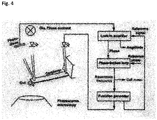
- Figure 4 shows a setup of a measuring device (or picobalance) as a block diagram.
- the intensity modulated blue laser excites an oscillatory movement of the microcantilever, which is detected by an infrared laser (red) reflected from the free cantilever end onto a four-quadrant photodiode.
- a near infrared laser can be used for excitation and a visible red laser.
- different wavelengths can be used with different advantages and disadvantages as know to the person skilled in the art, as e.g. fluorescence may be limited in wavelength.
- a lock-in amplifier For high time resolution measurements, a phase-locked loop instantaneously tracks the natural resonance frequency of the cantilever.
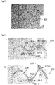
- Figure 5 shows a cantilever 91 where the platform 92 is parallel to the cantilever beam 94 at rest and connected to the beam 94 via a small connector 95.
- the platform 92 is attached with a distance to the free end of the cantilever 91, parallel to the cantilever beam 94.
- a cell 93 is attached to the platform 52.
- the cantilever beam 94 is shown oscillating at a higher flexural mode than the fundamental one.
- the antinode 96 of the cantilever beam 94 is shown in Figure 5 .
- the platform 92 is linked to the antinode 96 of the cantilever beam 94. In other examples the platform 92 is linked near an antinode of the cantilever beam. Antinodes provide the highest oscillation amplitude for a certain eigenmode and therefore provide the highest mass sensitivity of the cantilever beam 94. The whole platform 92 moves with the amplitude of the antinode 96.
- the number and location of antinodes 96 depends on the vibration eigenmode of the cantilever 91 and its geometry.
- the cantilever 91 can be oscillated with several eigenmodes simultaneously.
- a cantilever can have more than one platform, as shown in Figures 6a and 6b.
- Figure 6a shows a cantilever 101 with two platforms 102-1, 102-2 and Figure 6b also shows a cantilever 111 with two platforms 112-1, 112-2.
- each platform 102-1, 102-2 is linked to or near an antinode 106, 107.
- each platform 112-1, 112-2 is linked to or near an antinode 116, 117.
- the cantilever beam 104, 114 is shown oscillating at a higher eigenmode than the fundamental one.
- the antinodes 106, 107 of the cantilever beam 104 are shown in Figure 6a.
- Figure 6b shows the antinodes 116, 117 of the cantilever beam 114.
- Fig. 6a and 6b show a cantilever oscillating at a certain eigenmode. However, oscillating at several eigenmodes simultaneously is possible, however it is not shown for simplicity.
- the cantilever beam 104, 114 has one platform 102-1, 112-1 located at antinode 106, 116 and another platform 102-2, 112-2 located at antinode 107, 117 of the cantilever 101, 111.
- the platforms 102-1, 102-2 have the same orientation relative to the cantilever beam 104. Both are arranged at the same side of the cantilever beam 104.
- the platforms 112-1, 112-2 are arranged on different sides of the cantilever beam 114.
- Platforms 102-1, 102-2 of Figure 6a and platforms 112-1, 112-2 of Figure 6b are parallel to the cantilever beam 104 at rest (no oscillation), 114.
- the platforms may have any orientation relative to the cantilever, as shown in Figure 2 or 3 , for example.
- any of the aspects relating to the methods, apparatuses and systems described in this document can be combined.
- any combination between features relating to different subject matters is considered to be disclosed with this application. All features can be combined providing synergetic effects that are more than the simple summation of the features.
Landscapes
- Physics & Mathematics (AREA)
- Acoustics & Sound (AREA)
- Health & Medical Sciences (AREA)
- Life Sciences & Earth Sciences (AREA)
- Chemical & Material Sciences (AREA)
- Analytical Chemistry (AREA)
- Biochemistry (AREA)
- General Health & Medical Sciences (AREA)
- General Physics & Mathematics (AREA)
- Immunology (AREA)
- Pathology (AREA)
- Apparatus Associated With Microorganisms And Enzymes (AREA)
- Length Measuring Devices With Unspecified Measuring Means (AREA)
Priority Applications (2)
| Application Number | Priority Date | Filing Date | Title |
|---|---|---|---|
| DE102018117207.9A DE102018117207A1 (de) | 2017-07-18 | 2018-07-17 | Microcantilever |
| US16/038,250 US10830734B2 (en) | 2017-07-18 | 2018-07-18 | Microcantilever |
Applications Claiming Priority (1)
| Application Number | Priority Date | Filing Date | Title |
|---|---|---|---|
| EP17001238 | 2017-07-18 |
Publications (1)
| Publication Number | Publication Date |
|---|---|
| EP3431982A1 true EP3431982A1 (de) | 2019-01-23 |
Family
ID=59501131
Family Applications (1)
| Application Number | Title | Priority Date | Filing Date |
|---|---|---|---|
| EP18000307.1A Withdrawn EP3431982A1 (de) | 2017-07-18 | 2018-03-29 | Mikroausleger |
Country Status (3)
| Country | Link |
|---|---|
| US (1) | US10830734B2 (de) |
| EP (1) | EP3431982A1 (de) |
| DE (1) | DE102018117207A1 (de) |
Cited By (1)
| Publication number | Priority date | Publication date | Assignee | Title |
|---|---|---|---|---|
| CN113514632A (zh) * | 2021-04-20 | 2021-10-19 | 中国科学技术大学 | 基于纳米抗体的微悬臂梁免疫传感方法 |
Families Citing this family (1)
| Publication number | Priority date | Publication date | Assignee | Title |
|---|---|---|---|---|
| US10976238B2 (en) * | 2019-01-30 | 2021-04-13 | Xi'an Jiaotong University | Measurement apparatus for micro- and nano-scale material and measurement method thereof |
Citations (7)
| Publication number | Priority date | Publication date | Assignee | Title |
|---|---|---|---|---|
| US5992226A (en) * | 1998-05-08 | 1999-11-30 | The United States Of America As Represented By The Secretary Of The Navy | Apparatus and method for measuring intermolecular interactions by atomic force microscopy |
| US6016686A (en) * | 1998-03-16 | 2000-01-25 | Lockheed Martin Energy Research Corporation | Micromechanical potentiometric sensors |
| WO2004012201A2 (en) * | 2002-07-31 | 2004-02-05 | The Secretary Of State For Trade & Industry Of Her Majesty's Britannic Government | Method of and apparatus for calibrating cantilevers |
| US20060219010A1 (en) * | 2005-03-29 | 2006-10-05 | Bojan Ilic | Detection of small bound mass |
| US20070169553A1 (en) * | 2006-01-23 | 2007-07-26 | Drexel University | Self-exciting, self-sensing piezoelectric cantilever sensor |
| US20110067150A1 (en) * | 2009-09-16 | 2011-03-17 | Hoelscher Hendrik | Cantilever with paddle for operation in dual-frequency mode |
| EP2908123A1 (de) * | 2014-02-17 | 2015-08-19 | Universität Basel | Messvorrichtung und Verfahren zur Bestimmung einer der Masse und der mechanischen Eigenschaften eines biologischen Systems |
Family Cites Families (12)
| Publication number | Priority date | Publication date | Assignee | Title |
|---|---|---|---|---|
| US5475318A (en) * | 1993-10-29 | 1995-12-12 | Robert B. Marcus | Microprobe |
| WO2003102218A2 (en) * | 2002-06-03 | 2003-12-11 | Arizona Board Of Regents | Hybrid microcantilever sensors |
| US7270952B2 (en) * | 2002-09-24 | 2007-09-18 | Intel Corporation | Detecting molecular binding by monitoring feedback controlled cantilever deflections |
| US7521257B2 (en) * | 2003-02-11 | 2009-04-21 | The Board Of Regents Of The Nevada System Of Higher Education On Behalf Of The University Of Nevada, Reno | Chemical sensor with oscillating cantilevered probe and mechanical stop |
| US7759924B2 (en) * | 2003-11-25 | 2010-07-20 | Northwestern University | Cascaded MOSFET embedded multi-input microcantilever |
| US7966898B2 (en) * | 2006-07-28 | 2011-06-28 | California Institute Of Technology | Polymer NEMS for cell physiology and microfabricated cell positioning system for micro-biocalorimeter |
| US8252598B2 (en) * | 2006-11-27 | 2012-08-28 | University Of South Carolina | Method of sensing chemical and bio-molecular analytes and sensing system using a microcantilever |
| US7992431B2 (en) * | 2006-11-28 | 2011-08-09 | Drexel University | Piezoelectric microcantilevers and uses in atomic force microscopy |
| US20100028902A1 (en) * | 2007-02-26 | 2010-02-04 | Brown Scott C | Living cell force sensors and methods of using same |
| JP5813966B2 (ja) * | 2011-03-03 | 2015-11-17 | 株式会社日立ハイテクサイエンス | 変位検出機構およびそれを用いた走査型プローブ顕微鏡 |
| US9772305B2 (en) * | 2011-09-15 | 2017-09-26 | Arizona Board Of Regents On Behalf Of Arizona State University | System and method for small molecule detection |
| US10191004B2 (en) * | 2014-10-21 | 2019-01-29 | University Of South Carolina | Microcantilever based selective volatile organic compound (VOC) sensors and methods |
-
2018
- 2018-03-29 EP EP18000307.1A patent/EP3431982A1/de not_active Withdrawn
- 2018-07-17 DE DE102018117207.9A patent/DE102018117207A1/de not_active Withdrawn
- 2018-07-18 US US16/038,250 patent/US10830734B2/en not_active Expired - Fee Related
Patent Citations (7)
| Publication number | Priority date | Publication date | Assignee | Title |
|---|---|---|---|---|
| US6016686A (en) * | 1998-03-16 | 2000-01-25 | Lockheed Martin Energy Research Corporation | Micromechanical potentiometric sensors |
| US5992226A (en) * | 1998-05-08 | 1999-11-30 | The United States Of America As Represented By The Secretary Of The Navy | Apparatus and method for measuring intermolecular interactions by atomic force microscopy |
| WO2004012201A2 (en) * | 2002-07-31 | 2004-02-05 | The Secretary Of State For Trade & Industry Of Her Majesty's Britannic Government | Method of and apparatus for calibrating cantilevers |
| US20060219010A1 (en) * | 2005-03-29 | 2006-10-05 | Bojan Ilic | Detection of small bound mass |
| US20070169553A1 (en) * | 2006-01-23 | 2007-07-26 | Drexel University | Self-exciting, self-sensing piezoelectric cantilever sensor |
| US20110067150A1 (en) * | 2009-09-16 | 2011-03-17 | Hoelscher Hendrik | Cantilever with paddle for operation in dual-frequency mode |
| EP2908123A1 (de) * | 2014-02-17 | 2015-08-19 | Universität Basel | Messvorrichtung und Verfahren zur Bestimmung einer der Masse und der mechanischen Eigenschaften eines biologischen Systems |
Non-Patent Citations (1)
| Title |
|---|
| YEN Y K ET AL: "A novel, electrically protein-manipulated microcantilever biosensor for enhancement of capture antibody immobilization", SENSORS AND ACTUATORS B: CHEMICAL: INTERNATIONAL JOURNAL DEVOTED TO RESEARCH AND DEVELOPMENT OF PHYSICAL AND CHEMICAL TRANSDUCERS, ELSEVIER BV, NL, vol. 141, no. 2, 7 September 2009 (2009-09-07), pages 498 - 505, XP026501699, ISSN: 0925-4005, [retrieved on 20090627], DOI: 10.1016/J.SNB.2009.06.038 * |
Cited By (1)
| Publication number | Priority date | Publication date | Assignee | Title |
|---|---|---|---|---|
| CN113514632A (zh) * | 2021-04-20 | 2021-10-19 | 中国科学技术大学 | 基于纳米抗体的微悬臂梁免疫传感方法 |
Also Published As
| Publication number | Publication date |
|---|---|
| DE102018117207A1 (de) | 2019-01-24 |
| US20190025257A1 (en) | 2019-01-24 |
| US10830734B2 (en) | 2020-11-10 |
Similar Documents
| Publication | Publication Date | Title |
|---|---|---|
| KR101569960B1 (ko) | 다이나믹 탐침 검출 시스템 | |
| JP2730673B2 (ja) | 超音波を導入するカンチレバーを用いた物性の計測方法および装置 | |
| EP2250480B1 (de) | Spm-messvorrichtung, messsonde und messverfahren | |
| JP5813966B2 (ja) | 変位検出機構およびそれを用いた走査型プローブ顕微鏡 | |
| US10830734B2 (en) | Microcantilever | |
| US20150177126A1 (en) | Method and system for characterization of nano- and micromechanical structures | |
| US20160231352A1 (en) | System and method of performing atomic force measurements | |
| JP5958642B2 (ja) | 原子間力顕微鏡を用いた表面電荷密度測定装置 | |
| US20030033863A1 (en) | Atomic force microscopy for high throughput analysis | |
| WO2007072706A1 (ja) | 走査型プローブ顕微鏡 | |
| JP2003329565A (ja) | 走査プローブ顕微鏡 | |
| JP2001108601A (ja) | 走査型プローブ顕微鏡 | |
| EP2781925B1 (de) | Versiegelte afm-zelle | |
| JP2008241619A (ja) | カンチレバー、バイオセンサ、及びプローブ顕微鏡 | |
| JP2012093325A (ja) | 原子間力顕微鏡用のカンチレバー、原子間力顕微鏡、および、原子間力の測定方法 | |
| JP6001728B2 (ja) | 変位検出機構およびそれを用いた走査型プローブ顕微鏡 | |
| US9057706B2 (en) | Optical cantilever based analyte detection | |
| JP7444017B2 (ja) | 走査型プローブ顕微鏡 | |
| JPH0526662A (ja) | 走査型原子間力,磁気力顕微鏡及びその類似装置 | |
| JP3450460B2 (ja) | 走査型プローブ顕微鏡 | |
| US20040052687A1 (en) | Apparatus for parallel detection of the behaviour of mechanical micro-oscillators | |
| KR20090130537A (ko) | 원자력 현미경용 캔틸레버의 고정체 | |
| JPH07174767A (ja) | 走査型プローブ顕微鏡 | |
| JP2019049487A (ja) | 走査型プローブ顕微鏡の校正方法 | |
| WO2021044934A1 (ja) | 走査型プローブ顕微鏡及び走査型プローブ顕微鏡の駆動制御装置 |
Legal Events
| Date | Code | Title | Description |
|---|---|---|---|
| PUAI | Public reference made under article 153(3) epc to a published international application that has entered the european phase |
Free format text: ORIGINAL CODE: 0009012 |
|
| STAA | Information on the status of an ep patent application or granted ep patent |
Free format text: STATUS: THE APPLICATION HAS BEEN PUBLISHED |
|
| AK | Designated contracting states |
Kind code of ref document: A1 Designated state(s): AL AT BE BG CH CY CZ DE DK EE ES FI FR GB GR HR HU IE IS IT LI LT LU LV MC MK MT NL NO PL PT RO RS SE SI SK SM TR |
|
| AX | Request for extension of the european patent |
Extension state: BA ME |
|
| STAA | Information on the status of an ep patent application or granted ep patent |
Free format text: STATUS: REQUEST FOR EXAMINATION WAS MADE |
|
| 17P | Request for examination filed |
Effective date: 20190723 |
|
| RBV | Designated contracting states (corrected) |
Designated state(s): AL AT BE BG CH CY CZ DE DK EE ES FI FR GB GR HR HU IE IS IT LI LT LU LV MC MK MT NL NO PL PT RO RS SE SI SK SM TR |
|
| STAA | Information on the status of an ep patent application or granted ep patent |
Free format text: STATUS: EXAMINATION IS IN PROGRESS |
|
| 17Q | First examination report despatched |
Effective date: 20200706 |
|
| STAA | Information on the status of an ep patent application or granted ep patent |
Free format text: STATUS: THE APPLICATION IS DEEMED TO BE WITHDRAWN |
|
| 18D | Application deemed to be withdrawn |
Effective date: 20231121 |