EP3432035B1 - Verfahren und elektronisches zirkuit zur verarbeitung von von einem ionisierenden strahlungsdetektor generierten puls - Google Patents
Verfahren und elektronisches zirkuit zur verarbeitung von von einem ionisierenden strahlungsdetektor generierten puls Download PDFInfo
- Publication number
- EP3432035B1 EP3432035B1 EP18183519.0A EP18183519A EP3432035B1 EP 3432035 B1 EP3432035 B1 EP 3432035B1 EP 18183519 A EP18183519 A EP 18183519A EP 3432035 B1 EP3432035 B1 EP 3432035B1
- Authority
- EP
- European Patent Office
- Prior art keywords
- pulse
- interest
- shaping
- amplitude
- measurement
- Prior art date
- Legal status (The legal status is an assumption and is not a legal conclusion. Google has not performed a legal analysis and makes no representation as to the accuracy of the status listed.)
- Active
Links
Images


Classifications
-
- G—PHYSICS
- G01—MEASURING; TESTING
- G01T—MEASUREMENT OF NUCLEAR OR X-RADIATION
- G01T1/00—Measuring X-radiation, gamma radiation, corpuscular radiation, or cosmic radiation
- G01T1/16—Measuring radiation intensity
- G01T1/17—Circuit arrangements not adapted to a particular type of detector
-
- G—PHYSICS
- G01—MEASURING; TESTING
- G01T—MEASUREMENT OF NUCLEAR OR X-RADIATION
- G01T1/00—Measuring X-radiation, gamma radiation, corpuscular radiation, or cosmic radiation
- G01T1/16—Measuring radiation intensity
- G01T1/24—Measuring radiation intensity with semiconductor detectors
- G01T1/247—Detector read-out circuitry
Definitions
- the invention relates to detectors of ionizing radiation, in particular X-ray or gamma photon radiation.
- Ionizing radiation detection devices based on gaseous, semiconductor or scintillator detector materials, make it possible to obtain electrical pulses formed by interactions of radiation in the detector material.
- the amplitude of each pulse depends on the energy deposited by the radiation during each interaction.
- These devices are frequently used in applications requiring knowledge of the energy of the ionizing radiation incident to the detector.
- the fields of application are wide, and include in particular non-destructive testing, for example baggage testing, medical diagnostics or measurements in nuclear installations.
- the devices include an electronic circuit for processing the pulses making it possible to estimate their amplitudes as precisely as possible.
- a circuit for shaping the pulses generated by the detector is used, so as to be able to estimate the amplitude of each pulse with precision.
- Shaping circuits are generally parameterized by a time constant, or shaping duration, according to which each pulse is analyzed. It is generally agreed that the optimum time constant is greater than or equal to the rise time of the electrical pulses formed by the detector.
- This method includes an estimate of the ballistic deficit of each pulse processed by the second shaping time, that is to say the longest shaping time.
- the estimation of the ballistic deficit is estimated by combining a subtraction of the respective amplitudes of the pulses resulting from the two shaping circuits, with a ratio between the two shaping times.
- the ballistic deficit thus estimated is added to the pulse processed by the second shaping circuit, the main objective being to optimize the energy resolution.
- the inventors of the present invention considered that the method described above is difficult to apply to situations in which a low volume detector exposed to high count rates is used. They propose a method for processing a pulse generated by a detector, compatible with use at a high count rate, and making it possible to maintain an estimate of the energy, corresponding to each interaction, reliable and robust.
- a first object of the invention is a method for processing a pulse generated by an ionizing radiation detector, according to claim 1.
- a measurement pulse is thus obtained, the first amplitude of which is corrected.
- the second shaping time can be longer or shorter than the first shaping time.
- the invention also relates to an electronic processing circuit according to claim 15.
- the device comprises a detector 10, capable of interacting with ionizing radiation 5 emitted by an irradiation source 2.
- ionizing radiation is meant radiation formed of particles capable of ionizing matter. It may be alpha radiation, beta radiation, X-type or gamma-type photon radiation, or else neutron radiation.
- the radiation is photonic radiation of the X or gamma type, formed of photons whose energy is for example between 1 keV and 2 MeV.
- the detector comprises a semiconductor material, of CdTe type, but it could also be a semiconductor material commonly used for the detection of ionizing radiation, for example of Ge type, If, CdZnTe.
- a particle in this case a photon, of ionizing radiation 5 interacts in the detector 10
- charge carriers are formed and migrate towards a collection electrode 11, for example. an anode.
- the quantity of charges Q collected by the electrode 11 depends, preferably linearly, on the energy E released by the particle under the effect of the interaction.
- detectors for example scintillators coupled to a photon / charge carrier converter, or a gas detector of the ionization chamber type, can be used, since they allow the collection of a quantity of charges Q under the effect of an energy E released by the ionizing radiation during an interaction in the detector 10.
- the term amplitude denotes the maximum height of a pulse. It can also be the integral of a pulse, or any other function of the maximum height or of the integral of the pulse.
- the electronic processing circuit 12 may include an analog-to-digital converter not shown in the figure. figure 1A , the latter possibly being arranged between the preamplifier 20 and the shaping circuit 30, or between the shaping circuit 30 and the correction circuit 40, or between the correction circuit 40 and the analyzer 50, or in downstream of the latter.
- an analog-to-digital converter not shown in the figure. figure 1A , the latter possibly being arranged between the preamplifier 20 and the shaping circuit 30, or between the shaping circuit 30 and the correction circuit 40, or between the correction circuit 40 and the analyzer 50, or in downstream of the latter.
- the electronic circuits described above are either analog or digital.
- the figure 1B 10 shows a pixelated detector, comprising at least two collection electrodes 11 and 11a, each collecting electrode being respectively connected to a processing circuit 12, 12 a.
- the collecting electrode 11 a is referred to as the adjacent electrode, as it is adjacently disposed on the collection electrode 11.
- the processing circuit 12 is such as that shown in connection with the figure 1A .
- the processing circuit 12 a comprises a preamplifier 20 a , an amplifier 30 a , a correction circuit 40 a and an analyzer 50 a such as those described in connection with the processing circuit 12.
- a pixelized detector can comprise several tens. or even hundreds of collection electrodes. These electrodes can be arranged in a line or a two-dimensional matrix.
- the figure 1C shows schematically the pre-amplification circuit 20 described above. It can be shown schematically by an amplifier 21 connected to a feedback loop RC, modeled by a resistor R in parallel with a capacitor C.
- the rise time t r corresponds to the time interval between the start of the measurement pulse S and its maximum. Such a curve is represented on the figures 2A and 2B .
- the rise time t r is usually designated by the English term rise time.
- the figure 1D shows diagrammatically the amplifier 30, the latter comprising a delay line 31, applying a delay ⁇ t to the pulse, so as to form a delayed pulse S ⁇ t .
- the principle of such a delay line is known, and is described more precisely in the patent. US7652242 .
- the shaped pulse S ' is more symmetrical than the S pulse from the preamplifier. Its amplitude A ' depends, preferably by a linear relationship, on the energy given up by the ionizing radiation during its interaction in the detector 10.
- the figures 2A and 2B represent two situations, corresponding respectively to a first delay line applying a first delay ⁇ t 1 and to a second delay line applying a second delay ⁇ t 2 to the measurement pulse S, with ⁇ t 2 > ⁇ t 1 .
- the first delay line performs so-called short shaping, while the second delay line performs long shaping.
- the rise time t ' r of a shaped pulse is frequently greater than or equal to the rise time t r of the measuring pulse S.
- the amplitude of the shaped pulse takes into account the totality of the charge Q collected by the electrode.
- the rise time t ′ r depends on the shaping time ⁇ t taken into account by the shaping circuit 30 of the measurement pulse.
- the pulse does not carry relevant information as to the energy of the incident radiation.
- Such a phenomenon can for example occur in baggage screening type applications, in which the baggage is exposed to intense beams of radiation, so as to minimize control time. It can also occur when carrying out nuclear measurements under strong radiation, for example on nuclear components with high activity.
- the figure 3A shows a first pulse S ' 1 ( t 1 ) and a second pulse S' 1 ( t 2 ) formed respectively from a measurement pulse S ( t 1 ) a first instant t 1 and from a pulse of measure S ( t 2 ) at a second instant t 2 .
- the two pulses S ' 1 ( t 1 ) and S' 1 ( t 2 ) result from a delay line shaping circuit, taking into account a delay ⁇ t 1 of 50 ns.
- the measurement pulses S ( t 1 ) and S ( t 2 ) processed by the shaping circuit have a rise time t r of 100 ns.
- the pulses S ' 1 ( t 1 ) and S ' 1 ( t 2 ) correspond to the emission peak of 57 Co, at the energy of 122 keV. It can be seen that their respective amplitudes A ' 1 ( t 1 ) and A' 1 ( t 2 ) are not identical, although they correspond to the same energy.
- the conversion gain corresponding to a ratio between the amplitude A ′ 1 of the shaped pulse S ' 1 and the energy of the interaction that generated the measurement pulse S , is not stable over time.
- the figure 3B represents two pulses S ' 2 ( t 1 ) and S' 2 ( t 2 ) shaped under the same experimental conditions as the pulses of the figure 3A , by modifying the shaping time.
- a delay line based on a second delay ⁇ t 2 equal to 200 ns. It can be seen that their respective amplitudes A ' 2 ( t 1 ) and A' 2 ( t 2 ) are identical, which attests to the stability of the conversion gain in this configuration based on a long shaping time ⁇ t 2 .
- the drift effect of the conversion gain as a function of the shaping time can be observed on the figures 3C and 3D , representing energy spectra of the radiation emitted by a source of 57 Co acquired at different times, respectively by adopting a short (50 ns) and long (200 ns) shaping time.
- the drift of the conversion gain results in a progressive shift of the spectra towards the high energies.
- the different spectra are superimposed, the conversion gain being stable.
- the shaping circuit can be a filter making it possible to generate a pulse of configurable shape, for example a Gaussian, triangular or trapezoidal shape, this type of circuit being usual in the field of X or gamma spectrometry.
- the pulse response of such a circuit is a pulse of predetermined geometric shape and configurable by the shaping time.
- Gaussian filters generating a Gaussian shaped pulse and whose width at half the height is configurable, is common in the field of gamma or X spectrometry.
- the use of such filters is described in the publication Salathe M. "Optimized digital filtering techniques for radiation detection with HPGe detectors".
- the filter can also be triangular, the base of the triangle being configurable, or trapezoidal, the width of the apex of the pulse being configurable.
- the figure 2C schematizes for example a pulse S at the output of a preamplifier, as well as pulses S " 1 and S" 2 shaped with a trapezoidal filter by considering respectively a first shaping duration ⁇ t 1 and a second duration ⁇ t 2 of formatting, with ⁇ t 2 > ⁇ t 1 .
- a short shaping time ⁇ t 1 limits the stacks, but is accompanied by a temporal drift of the conversion gain.
- a long shaping time ⁇ t 2 increases the probability of observing a stacking, but benefits from a stable conversion gain. The inventors took advantage of this observation to propose a process, the main steps of which are described below, in connection with the figures 4A and 4C .
- Step 100 detection: the detector 10 is exposed to incident ionizing radiation 5, a particle of which interacts in the detector to form charge carriers collected by an electrode.
- Step 110 preamplification: the collected charge Q is integrated by a preamplifier, so as to form a pulse S, called a measurement pulse, generally asymmetrical, having a rise time t r and an exponential decrease.
- the measurement pulse is formed at a measurement instant t .
- Step 130 first shaping of the measurement pulse S according to a first shaping duration ⁇ t 1 .
- the shaping is obtained with a first delay line circuit 31, as shown in figure figure 4B , the delay line generating a delayed pulse S ⁇ t 1 , as explained in connection with figure 2A .
- the first delay line 31 is connected to the inverting input of a subtracter 34, the non-inverting input of which receives the measurement pulse S.
- the first shaping time ⁇ t 1 is less than the rise time t r of the measurement pulse S at the output of the preamplifier 20. This step generates a first shaping pulse S ′ 1 of first amplitude A ′ 1 .
- Step 140 second shaping of the measurement pulse S according to a second shaping duration ⁇ t 2 .
- the shaping is achieved with a second delay line circuit 32 as shown in Figure figure 4B , the delay line generating a delayed pulse S ⁇ t 2 , as explained in connection with figure 2B .
- the second delay line 32 is connected to the inverting input of a subtracter 35, the non-inverting input of which receives the measurement pulse S , coming from the preamplifier 20.
- the second shaping time ⁇ t 2 can be greater. or equal to the rise time t r of the output pulse S of the preamplifier 20. This step generates a second shaped pulse S ′ 2 of second amplitude A ′ 2 .
- Steps 150, 160 and 170 described below are implemented by the correction circuit 40, illustrated in figure 4C .
- the correction circuit 40 comprises a comparison unit 44, a calculation unit 46 and a correction unit 48. It may include a selection unit 42 when the optional step 120, described below, is implemented. However, recourse to the selection step 120 is recommended.
- Step 150 comparison of the first and the second amplitude.
- the comparison unit 44 performs a comparison of the amplitudes A ' 1 and A' 2 of the respective pulses S ' 1 and S' 2 , so as to calculate a comparison factor k .
- the comparison factor k is a ratio between the amplitudes A ' 1 and A' 2 .
- k TO ′ 1 TO ′ 2 .
- the objective of the following steps is to multiply the first measured amplitude A ' 1 by a correction factor 1 ⁇ , so as to compensate for the time drift of the conversion gain.
- the factor of correction ⁇ can be equal to the comparison factor k.
- the inventors have considered that it is preferable to establish a correction factor from comparison factors k respectively calculated for a certain number of pulses, called pulses of interest.
- Step 160 calculation of the correction factor. From the comparison factor k calculated during step 150, the calculation unit 46 determines a correction factor ⁇ .
- the correction factor ⁇ is determined as a function of comparison factors k 1 .... k N respectively obtained by applying steps 110 to 150 to pulses S 1 .... S N , called pulses of interest, previously formed and / or after the measurement pulse S.
- pulses of interest are formed by the detector before or after the measurement instant t .
- the term pulse of interest designates a pulse generated by the detector, before or after the measurement pulse S , and for which the comparison factor is kept.
- the correction factor ⁇ can be calculated as a function of the mean value or of the median value of the comparison factors determined for different pulses of interest prior to the measurement pulse, and stored in the calculation unit 46, to which we adds the comparison factor k established for the measurement pulse S , calculated during step 150.
- ⁇ mean ( k 1 , ...., k N , k ).
- the pulses of interest S 1 .... S N are the N pulses extending during a time range ⁇ t called the time range of interest, this time range extending after and / or prior to the measurement instant t at which the measurement pulse S is formed.
- the number N is an integer designating the number of pulses of interest used to determine the correction factor. It can be between 1 and 10,000, or even more.
- the time range of interest ⁇ t extends before, around, or after the measurement instant t , the duration of the time range of interest possibly being for example 1 second or a few seconds.
- the duration of the time range of interest ⁇ t is defined in such a way that it can be considered that during this range, the conversion gain of the detector does not change, or in a negligible manner.
- N 0.
- the first correction factor is only determined as a function of the comparison factor calculated for the measurement pulse. Then, as each measurement pulse S is processed, the number N is incremented at each measurement pulse, until a predetermined maximum value N max is reached. The correction factor ⁇ is then determined by taking a sliding average (or median) of the N max comparison factors respectively determined for the N max pulses of interest prior to the measurement pulse.
- the number N of pulses of interest whose comparison factor is taken into account for the calculation of the correction factor is fixed at a predetermined value. No correction factor is applied to the measurement pulses until N pulses of interest are available, the comparison factor of which is determined. From this instant, the correction factor is determined by performing a sliding average of the N comparison factors respectively determined for the N pulses of interest.
- the pulses of interest can be distributed according to a time range of interest extending before and after the measurement pulse S. It may for example be NOT max 2 pulses acquired before the measurement and NOT max 2 pulses acquired after the measurement pulse.
- steps 160 and 170 are implemented in post-processing, that is to say after the time range of interest ⁇ t.
- the correction is then deferred with respect to the measurement instant t.
- the correction factor ⁇ is determined without taking into account the comparison factor of the measurement pulse, but only on the basis of the comparison factors respectively determined from pulses of interest.
- Step 170 correction.
- the correction factor ⁇ is applied to the first shaped pulse S ' 1 , the amplitude of which A' 1 is multiplied by 1 ⁇ .
- We then obtain a corrected amplitude TO ′ vs 1 ⁇ ⁇ TO ′ 1 .
- the correction is performed by a correction unit 48 of the processing circuit 40.
- the correction unit uses the correction factor ⁇ calculated by the calculation unit 46.
- steps 100 to 170 are repeated during the detection of another measurement pulse S.
- each comparison factor comprises a normalized difference between the amplitudes A ′ 2 and A ′ 1 .
- the method described in connection with steps 100 to 170 makes it possible to determine an amplitude A ′ 1 of pulses S ′ 1 shaped according to a short shaping time, which is compatible with using the detector in high gear. count rate.
- the pulse thus shaped is corrected, so as to attenuate, or even eliminate, the effect of drift of the conversion gain demonstrated by the inventors.
- the advantage is to use a short shaping time, conducive to high counting rates, while limiting the drawback associated with the temporal instability of the conversion gain.
- the method comprises a step 120 of selecting the pulses for which the comparison factors k are determined: these are the pulses of interest and possibly the measurement pulse.
- Step 120 is implemented by the selection unit 42.
- the objective is to avoid taking into account the comparison factors resulting from pulses formed following a stack of two interactions originating from two different particles, or pulses resulting from a collection of charge carriers shared between two adjacent electrodes, when the detector is connected to several electrodes as shown in figure figure 1B .
- the selection makes it possible to retain only pulses formed by a single particle, and collected by a single electrode. The selection is described below in connection with a measurement pulse, knowing that it can be carried out for each pulse of interest.
- the selection unit 42 applies one or more selection criteria to the measurement pulse S coming from the preamplifier 20, or to the first or the second shaped pulse.
- a selection criterion may be a duration of the first shaped pulse S ′ 1 and / or of the second shaped pulse S ′ 2 above a predefined threshold. This selection criterion is illustrated on the figures 4D and 4E . On the figure 4D , there is shown a pulse S ' 1 shaped by the first shaping circuit, considering the first short time interval ⁇ t 1 of 50 ns. The duration ⁇ t 1 of the pulse S ' 1 above an amplitude threshold equal to 0.2 is shown by a double arrow.
- Another selection criterion may be based on the rise time t r of a measurement pulse S , or on the peaking time t ' r , 1 of a pulse S' 1 shaped by the first shaping circuit, or on the rise time (peaking time) t ′ r , 2 of a pulse S ′ 2 shaped by the second shaping circuit. When at least one of these rise times exceeds a certain value, the corresponding pulse is rejected.
- a selection criterion is a coincident detection of a pulse on an adjacent electrode 11 a .
- the charge Q generated can be collected by an electrode 10 while a complementary charge is collected by an adjacent electrode 11 a , during a step 100 a .
- the complementary charge Q a is integrated by a preamplifier 20 a during a step 120 a , so as to form an adjacent pulse S a .
- the adjacent pulse S a is shaped by the adjacent amplifier 30 a so as to obtain a first adjacent shaped pulse S ' 1, a according to the first shaping duration ⁇ t 1 (step 130 a ) and a second adjacent pulse S ′ 2, a shaped according to the second shaping duration ⁇ t 2 (step 140 a ).
- the selection unit 42 detects the presence of the adjacent pulse S a and / or the first adjacent shaped pulse S ' 1, a and / or the second adjacent shaped pulse S' 2, a .
- the selection unit compares the amplitudes A ′ 1, a and A ′ 2 , a of the pulses S ′ 1, a and S ′ 2, a with a predetermined threshold.
- a coincidence time range T d of 10 or 20 ns around the instant of detection t d of a pulse of interest is compared to a predetermined threshold.
- the selection unit 42 is based on one or more selection criteria to reject pulses which are not representative of the charge deposited by an interaction of a particle in the detector medium 10. These unwanted pulses are not taken into account in the calculation of the correction factor ⁇ .
- the selection step 120 makes it possible to obtain a correction factor independent of the count rate of the detector.
- the pulses selected by the selection unit 42 are processed by the comparison unit 44, the calculation unit 46 and the correction unit 48.
- the experimental device described above was subjected to prolonged irradiation, the irradiation source being an X-ray generator brought to a voltage of 120 kV.
- the correction factor was calculated by running a running average of 1024 comparison factors. It is observed that the correction factor ⁇ varies between an initial value of approximately 0.785 to a final value close to 0.835. This curve shows the relevance of considering a correction factor that varies over time.
- the figure 6A represents another embodiment of a method according to the invention. Steps 100, 110, 120, 130, 140, 100 a , 110 a , 120 a , 130 a and 140 a are identical to those described in connection with the figure 4A .
- the first shaping time ⁇ t 1 and the second shaping time ⁇ t 2 are less than the rise time t r of the measurement pulse S.
- ⁇ t 2 > ⁇ t 1 .
- the function f is obtained during a preliminary calibration phase, described in connection with steps 90 to 98.
- a first difference between this embodiment and the previous embodiment, shown in figure 4A is that the shaping circuits are based on shaping times shorter than the rise time t r of the measurement pulse S coming from the preamplifier 20. This makes it possible to limit the stacks and this embodiment is therefore well suited to high counting rates.
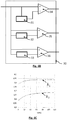
- the first, second and third shaping circuits are respectively delay line circuits comprising respectively the first delay line 31 and the second delay line 32 described in connection with the figures 1C and 1D , as well as a third delay line 33 applying a time delay equal to ⁇ t 3 to the pulse S coming from the preamplifier 20.
- the third shaping circuit is connected to the inverting input of a subtracter 36, of which l The non-inverting input receives the pulse S resulting from the preamplifier 20.
- the calibration step is now described, in connection with steps 80 to 98.
- Step 80 detection: the detector is exposed to incident ionizing radiation, a particle of which interacts in the detector to form charge carriers Q collected by an electrode.
- Step 90 preamplification: the collected charge is integrated into a preamplifier, so as to form a calibration pulse S calib .
- Step 91 first shaping of the calibration pulse S calib generated by the preamplifier, according to the first shaping duration ⁇ t 1 , so as to obtain a first shaped amplitude S ' calib -1 of first amplitude A ' calib -1 .
- Step 92 second shaping of the calibration pulse S calib generated by the preamplifier, according to the second shaping duration ⁇ t 2 so as to obtain a second shaped amplitude S ' calib -2 of second amplitude A' calib- 2 .
- Step 93 third shaping of the calibration pulse S calib generated by the preamplifier, according to the third shaping duration ⁇ t 3 so as to obtain a third shaped amplitude S ' calib- 3 of third amplitude A' calib- 3 .
- Step 94 calculation of a first comparison factor k 1 by comparison between the first amplitude A ' calib -1 and the third amplitude A' calib- 3 .
- k 1 TO ′ calib - 1 TO ′ calib - 3 .
- the first comparison factor k 1 is hereinafter called the auxiliary comparison factor.
- Step 95 calculation of a second comparison factor k 2 by comparison between the second amplitude A ' calib- 2 and the third amplitude A' calib- 3 .
- k 2 TO ′ calib - 2 TO ′ calib - 3 .
- Step 96 reiteration of steps 90 to 95, so as to establish a succession of pairs ( k 1 , k 2 ) as a function of time.
- the figure 6C represents a temporal evolution, over a period of 120 minutes, of the first comparison factor k 1 and of the second comparison factor k 2 .
- Step 98 development of the correction function. This involves establishing a correction function ⁇ , allowing a relationship to be established between the ratio k 1 k 2 and the first correction factor, called the auxiliary correction factor k 1 .
- the ratio k 1 k 2 corresponds to an amplitude shaped by the first shaping circuit on an amplitude shaped by the second shaping circuit. It therefore corresponds to the comparison factor k previously described, except that it is established for the calibration pulses. It is denoted by k calib .
- the first comparison factor k 1 corresponds to the correction factor ⁇ , making it possible to correct each first amplitude A ' 1 so as to obtain a corrected amplitude A c , to estimate an amplitude shaped with a long shaping time , that is to say greater than or equal to the rise time t r .
- the temporal evolution of k 1 is known (cf. figure 6C ).
- a correction function ⁇ can be obtained by determining the evolution, over several calibration pulses, of an average (or a median) of auxiliary correction factors k 1 as a function of an average (or a median) of calibration factors k calib .
- the correction function ⁇ represents the evolution of the correction factor ⁇ as a function of the comparison factor k . This function is shown on the figure 6E . It results from the calibration phase.
- k calib TO ′ 2 TO ′ 1 .
- the evolution of the second comparison factor k 2 is determined as a function of ratio k calib , so as to obtain the correction function f.
- the second comparison factor then corresponds to the auxiliary correction factor.
- first comparison factor k 1 or the second comparison factor k 2 are designated by the term auxiliary comparison factor.
- the correction amounts to realigning the spectrum Sp in the direction of the weaker channels, so as to correct the spectral drift resulting from the progressive increase in the conversion gain.
- This embodiment assumes that the conversion gain is stable during the acquisition period T a of the spectrum Sp .
- This embodiment makes it possible to simultaneously correct the amplitudes A ′ 1 shaped by the first shaping circuit.
- the method may include a digitization step, for example between the preamplifier and the amplifier, either between the amplifier and the correction circuit, or downstream of this. latest.
- the invention may be implemented in high count rate measurement applications, the applications may be in non-destructive testing, baggage testing, nuclear power or the field of diagnosis or medical treatment monitoring.
Landscapes
- Physics & Mathematics (AREA)
- Health & Medical Sciences (AREA)
- Life Sciences & Earth Sciences (AREA)
- General Physics & Mathematics (AREA)
- High Energy & Nuclear Physics (AREA)
- Molecular Biology (AREA)
- Spectroscopy & Molecular Physics (AREA)
- Measurement Of Radiation (AREA)
Claims (17)
- Verfahren zur Verarbeitung eines Impulses (S), der durch einen Detektor (10) für ionisierende Strahlung erzeugt wird, wobei der Detektor (10) dazu fähig ist, mit einer ionisierenden Strahlung (5) zu interagieren, um den Impuls zu erzeugen, dessen Amplitude (A) von einer Energie abhängt, die durch die ionisierende Strahlung während ihrer Interaktion in dem Detektor freigesetzt wird, wobei das Verfahren die folgenden Schritte umfasst:a) Aussetzen des Detektors gegenüber einer ionisierenden Strahlungsquelle (2), um zu einem Messzeitpunkt (t) einen Impuls (S), der als Messimpuls bezeichnet wird, zu erhalten;b) Formen des Messimpulses unter Einbeziehung einer ersten Formungsdauer (δt1 ) und Bestimmen einer ersten Amplitude (A'1 ) des so geformten Messimpulses;c) Korrigieren der während des Schrittes b) bestimmten ersten Amplitude unter Berücksichtigung eines Korrekturfaktors (η), um eine korrigiere Amplitude (A'c ) zu erhalten;wobei der Korrekturfaktor (η) unter Berücksichtigung von Impulsen, die als Impulse von Interesse (S1 ....SN, Scalib ) bezeichnet werden und die durch den Detektor während einer Aussetzung gegenüber der Quelle oder gegenüber einer Kalibrierquelle vor und/oder nach dem Messimpuls S während eines Zeitbereichs von Interesse (Δt) gebildet werden, bestimmt wird, wobei das Bestimmen des Korrekturfaktors für jeden Impuls von Interesse die folgenden Schritte umfasst:i) erstes Formen des Impulses von Interesse unter Einbeziehung der ersten Formungsdauer (δt1 ) und Messen einer ersten Amplitude des so geformten Impulses von Interesse;ii) zweites Formen des Impulses von Interesse unter Einbeziehung einer zweiten Formungsdauer (δt 2), die sich von der ersten Formungsdauer unterscheidet, und Messen einer zweiten Amplitude des so geformten Impulses von Interesse;iii) Vergleichen der ersten Amplitude und der zweiten Amplitude des Impulses von Interesse, um einen Vergleichsfaktor (k, k1, ...., kN, kcalib ) zu berechnen;wobei der Korrekturfaktor (η) in Abhängigkeit von den während des Schritts iii) für jeden Impuls von Interesse berechneten Vergleichsfaktoren (k, k1, ...., kN, kcalib ) bestimmt wird.
- Verfahren nach einem der vorhergehenden Ansprüche, das ferner Folgendes umfasst:- zweites Formen des Messimpulses unter Einbeziehung der zweiten Formungsdauer (δt2 ) und Bestimmen einer zweiten Amplitude (A'2 ) des so geformten Messimpulses;- Vergleichen der ersten Amplitude und der zweiten Amplitude des Messimpulses, um für den Messimpuls einen Vergleichsfaktor (k) zu berechnen;sodass der Korrekturfaktor (η) ferner in Abhängigkeit von dem für den Messimpuls berechneten Vergleichsfaktor (k) bestimmt wird.
- Verfahren nach einem der vorhergehenden Ansprüche, wobei der Korrekturfaktor (η) während des Schritts iii) in Abhängigkeit von einem Mittelwert oder einem Medianwert der jeweils für jeden Impuls von Interesse berechneten Vergleichsfaktoren bestimmt wird.
- Verfahren nach einem der vorhergehenden Ansprüche, wobei sich der Zeitbereich von Interesse (Δt) auf einer oder auf beiden Seiten des Messzeitpunkts (t) erstreckt.
- Verfahren nach einem der Ansprüche 1 bis 3, wobei der Zeitbereich von Interesse (Δt) einer Kalibrierphase entspricht, während der der Detektor einer Kalibrierquelle ausgesetzt wird, wobei das Verfahren dergestalt ist, dass während des Schritts iii) das Bestimmen des Korrekturfaktors für jeden Impuls von Interesse (Scalib ) ferner die folgenden Schritte umfasst:iv) drittes Formen des Impulses von Interesse unter Einbeziehung einer dritten Formungsdauer (δt 3), wobei die dritte Formungsdauer in jedem Fall größer als die zweite Formungsdauer (δt2 ) und die erste Formungsdauer (δt1 ) ist, und Bestimmen einer dritten Amplitude (A'calib-3 ) des so geformten Impulses von Interesse;v) Vergleichen der dritten Amplitude mit der ersten Amplitude des Impulses von Interesse, die sich aus dem Schritt i) ergibt, oder mit der zweiten Amplitude des Impulses von Interesse, die sich aus dem Schritt ii) ergibt, um einen sogenannten Hilfsvergleichsfaktor (k1, k2 ) zu berechnen;wobei das Bestimmen des Korrekturfaktors ferner das Erstellen einer Korrekturfunktion (ƒ) umfasst, die die Entwicklung des für Impulse von Interesse (Scalib ) bestimmten Vergleichsfaktors (kcalib ) in Abhängigkeit von dem für die Impulse von Interesse bestimmten Hilfsvergleichsfaktor darstellt, wobei das Verfahren ferner Folgendes umfasst:- zweites Formen des Messimpulses unter Einbeziehung der zweiten Formungsdauer (δt2 ) und Bestimmen einer zweiten Amplitude des Messimpulses (A'2 );- Vergleichen der ersten Amplitude (A'1 ) und der zweiten Amplitude (A'2 ) des Messimpulses, um für den Messimpuls einen Vergleichsfaktor (k) zu berechnen;sodass während des Schritts c) der Korrekturfaktor (η) in Abhängigkeit von einem Wert der Korrekturfunktion (ƒ) bestimmt wird, der ferner dem für den Messimpuls berechneten Vergleichsfaktor (k) entspricht.
- Verfahren nach einem der Ansprüche 1 bis 4, wobei:- die Schritte a) und b) während einer Erfassungsperiode (Ta ) für eine Vielzahl von Messimpulsen umgesetzt werden, wobei das Verfahren einen Schritt b') des Bildens eines Spektrums (Sp) umfasst, das ein Histogramm der während jedes Schritts b) geformten ersten Amplituden (A'1 ) darstellt;- die Schritte i) bis iii) für jeden während der Erfassungsperiode (Ta ) erfassten Impuls durchgeführt werden, sodass der Zeitbereich von Interesse (Δt) der Erfassungsperiode entspricht;- während des Schritts c) das Verfahren ein Anpassen des während des Schritts b') gebildeten Spektrums (Sp) unter Berücksichtigung des während des Schritts iii) berechneten Korrekturfaktors (η) umfasst, um ein korrigiertes Spektrum (Spc ) zu bilden.
- Verfahren nach einem der vorhergehenden Ansprüche, wobei das Bestimmen des Korrekturfaktors einen Schritt des Auswählens der Impulse von Interesse umfasst, wobei der Schritt des Auswählens für jeden Impuls von Interesse Folgendes umfasst:- Bestimmen eines Kriteriums des Impulses von Interesse oder des Impulses, der sich aus dem ersten oder dem zweiten Formen des Impulses von Interesse ergibt;- Vergleichen des Kriteriums mit einem Schwellenwert;- Auswählen des Impulses von Interesse in Abhängigkeit von dem Vergleich;sodass die Schritte i) bis iii) nur für die so ausgewählten Impulse von Interesse umgesetzt werden.
- Verfahren nach Anspruch 7, wobei der Schritt des Auswählens Folgendes umfasst:- Bestimmen einer Dauer des Impulses von Interesse, der sich aus dem ersten oder dem zweiten Formen ergibt;- Vergleichen der bestimmten Dauer mit einer Schwellendauer;- Auswählen des Impulses von Interesse in Abhängigkeit von dem Vergleich.
- Verfahren nach Anspruch 7, wobei der Schritt des Auswählens Folgendes umfasst:- Bestimmen einer Fläche und einer Amplitude des Impulses, der sich aus dem ersten oder dem zweiten Formen des Impulses von Interesse ergibt;- Berechnen eines Verhältnisses zwischen der so bestimmten Fläche und der so bestimmten Amplitude;- Vergleichen des Verhältnisses mit einem Verhältnisschwellenwert;- Auswählen des Impulses von Interesse in Abhängigkeit von dem Vergleich.
- Verfahren nach Anspruch 7, wobei der Schritt des Auswählens ein Bestimmen der zweiten zeitlichen Ableitung des Impulses von Interesse oder des Impulses, der sich aus dem ersten oder dem zweiten Formen des Impulses von Interesse ergibt, umfasst, wobei der Impuls von Interesse ausgewählt wird, wenn die zweite zeitliche Ableitung nicht gleich null ist oder nicht das Vorzeichen verändert.
- Verfahren nach Anspruch 7, wobei der Schritt des Auswählens Folgendes umfasst:- Bestimmen einer Anstiegszeit des Impulses von Interesse oder des Impulses, der sich aus dem ersten oder dem zweiten Formen des Impulses von Interesse ergibt;- Vergleichen der bestimmten Anstiegszeit mit einem Schwellenwert der Anstiegszeit;- Auswählen des Impulses von Interesse in Abhängigkeit von dem Vergleich.
- Verfahren nach einem der vorhergehenden Ansprüche, wobei der Detektor (10) Folgendes umfasst:- eine Sammelelektrode (11), die das Bilden des Messimpulses und der Impulse von Interesse ermöglicht;- eine Nachbarelektrode (11 a ) der Sammelelektrode, wobei die Nachbarelektrode dazu fähig ist, einen Impuls zu bilden, der als Nachbarimpuls bezeichnet wird und dessen Amplitude von einer Energie abhängt, die durch die ionisierende Strahlung während ihrer Interaktion in dem Detektor (10) freigesetzt wird;und wobei das Bestimmen des Korrekturfaktors (k) einen Schritt des Auswählens der Impulse von Interesse umfasst, wobei der Schritt des Auswählens für jeden Impuls von Interesse Folgendes umfasst:- Zuordnen eines Detektionszeitpunkts (td ) zu dem Impuls von Interesse;- Analysieren von Impulsen (Sa ), die durch die Nachbarelektrode (11 a ) in einem Koinzidenzzeitbereich (Td ), der sich um den Detektionszeitpunkt herum erstreckt, gebildet wurden;- Zurückweisen des Impulses von Interesse, wenn ein Impuls (Sa ), der sich aus der Nachbarelektrode (11 a ) ergibt, im Koinzidenzzeitbereich eine Schwellenamplitude überschreitet.
- Verfahren nach einem der vorhergehenden Ansprüche, wobei:- während des Schritts b) das Formen des Messimpulses (S) durchgeführt wird, indem eine erste zeitliche Verzögerung auf den Messimpuls angewendet wird, um einen verzögerten Messimpuls zu bilden, und indem der verzögerte Messimpuls von dem Messimpuls abgezogen wird, wobei die zeitliche Verzögerung der ersten Formungsdauer (δt1 ) entspricht;- während des Schritts i) das erste Formen des Impulses von Interesse (S1 ....SN, Scalib ) durchgeführt wird, indem die erste zeitliche Verzögerung auf den Impuls von Interesse angewendet wird, um einen ersten verzögerten Impuls von Interesse zu bilden, und indem der erste verzögerte Impuls von Interesse von dem Impuls von Interesse abgezogen wird;- während des Schritts ii) das zweite Formen des Impulses von Interesse (S1 ....SN, Scalib ) durchgeführt wird, indem eine zweite zeitliche Verzögerung auf den Impuls von Interesse angewendet wird, um einen zweiten verzögerten Impuls von Interesse zu bilden, und indem der zweite verzögerte Impuls von Interesse von dem Impuls von Interesse abgezogen wird, wobei die zweite zeitliche Verzögerung der zweiten Formungsdauer (δt2 ) entspricht.
- Verfahren nach einem der Ansprüche 1 bis 12, wobei:- während des Schritts b) das Formen des Messimpulses (S) durchgeführt wird, indem ein erster Filter auf den Messimpuls angewendet wird, wobei der erste Filter die erste Formungsdauer (δt1 ) berücksichtigt;- während des Schritts i) das erste Formen des Impulses von Interesse (S1 ....SN, Scalib ) durchgeführt wird, indem der erste Filter auf den Messimpuls angewendet wird;- während des Schritts ii) das zweite Formen des Impulses von Interesse (S1 ....SN, Scalib ) durchgeführt wird, indem ein zweiter Filter auf den Impuls von Interesse angewendet wird, wobei der zweite Filter die zweite Formungsdauer (δt2 ) berücksichtigt.
- Elektronische Schaltung zur Verarbeitung (12) eines Impulses, der durch einen Detektor für ionisierende Strahlung gebildet wird, wobei der Detektor Folgendes umfasst:- ein Material des Detektors (10), das dazu bestimmt ist, mit der ionisierenden Strahlung zu interagieren, um während einer Interaktion der ionisierenden Strahlung in dem Detektor elektrische Ladungen zu bilden;- eine Vorverstärkungsschaltung (20), die dazu fähig ist, die durch den Detektor erzeugten Ladungen zu sammeln und einen Impuls (S) zu bilden, der als Messimpuls bezeichnet wird und dessen Amplitude von der Menge der gesammelten Ladungen abhängt;wobei die elektronische Verarbeitungsschaltung Folgendes umfasst:- eine erste Formungsschaltung (31, 34), die dazu konfiguriert ist, den Messimpuls gemäß einer ersten Formungsdauer (δt1 ) zu formen, um einen ersten geformten Impuls zu erzeugen;- eine zweite Formungsschaltung (32, 35), die dazu konfiguriert ist, den Messimpuls gemäß einer zweiten zeitlichen Formungsdauer (δt 2), die größer als die erste Formungsdauer ist, zu formen, um einen zweiten geformten Impuls zu erzeugen;- eine Vergleichseinheit (44), die dazu fähig ist, den ersten geformten Impuls und den zweiten geformten Impuls zu vergleichen, um einen Vergleichsfaktor (k) zu bestimmen;- eine Recheneinheit (46), die dazu konfiguriert ist, in Abhängigkeit von dem Vergleichsfaktor (k) einen Korrekturfaktor (η) zu bestimmen;- eine Korrektureinheit (48), die dazu fähig ist, den durch die Recheneinheit bestimmten Korrekturfaktor auf den ersten geformten Impuls anzuwenden, um einen korrigierten Impuls zu bilden;wobei die elektronische Verarbeitungsschaltung dadurch gekennzeichnet ist, dass die Recheneinheit dazu fähig ist, die Schritte i) bis iii) des Verfahrens nach einem der Ansprüche 1 bis 14 auf Grundlage von Impulsen, die als Impulse von Interesse bezeichnet werden und die während eines Zeitbereichs von Interesse (Δt) durch den Detektor (10) gebildet werden, umzusetzen.
- Elektronische Schaltung nach Anspruch 15, wobei:- die erste Formungsschaltung (31, 34) eine erste Verzögerungsleitung umfasst, die dazu konfiguriert ist, eine erste Verzögerung, die der ersten Formungsdauer (δt1 ) entspricht, auf den Messimpuls anzuwenden, wobei die erste Formungsschaltung einen Subtrahierer umfasst, der dazu konfiguriert ist, den so verzögerten Impuls von dem Messimpuls abzuziehen;- die zweite Formungsschaltung (32, 35) eine zweite Verzögerungsleitung umfasst, die dazu konfiguriert ist, eine zweite Verzögerung, die der zweiten Formungsdauer (δt2 ) entspricht, auf den Messimpuls anzuwenden, wobei die zweite Formungsschaltung einen Subtrahierer umfasst, der dazu konfiguriert ist, den so verzögerten Impuls von dem Messimpuls abzuziehen.
- Elektronische Schaltung nach Anspruch 16, wobei:- die erste Formungsschaltung ein Filter ist, der dazu fähig ist, auf Grundlage des Messimpulses einen ersten Impuls mit einer vorgegebenen Form zu erzeugen, der durch die erste Formungsdauer (δt1 ) parametriert wird;- die zweite Formungsschaltung ein Filter ist, der dazu fähig ist, auf Grundlage des Messimpulses einen zweiten Impuls mit einer vorgegebenen Form zu erzeugen, der durch die zweite Formungsdauer (δt2 ) parametriert wird.
Applications Claiming Priority (1)
| Application Number | Priority Date | Filing Date | Title |
|---|---|---|---|
| FR1756775A FR3069066B1 (fr) | 2017-07-17 | 2017-07-17 | Procede de traitement d'une impulsion generee par un detecteur de rayonnement ionisant |
Publications (2)
| Publication Number | Publication Date |
|---|---|
| EP3432035A1 EP3432035A1 (de) | 2019-01-23 |
| EP3432035B1 true EP3432035B1 (de) | 2021-08-25 |
Family
ID=60765712
Family Applications (1)
| Application Number | Title | Priority Date | Filing Date |
|---|---|---|---|
| EP18183519.0A Active EP3432035B1 (de) | 2017-07-17 | 2018-07-13 | Verfahren und elektronisches zirkuit zur verarbeitung von von einem ionisierenden strahlungsdetektor generierten puls |
Country Status (3)
| Country | Link |
|---|---|
| US (1) | US10641909B2 (de) |
| EP (1) | EP3432035B1 (de) |
| FR (1) | FR3069066B1 (de) |
Families Citing this family (5)
| Publication number | Priority date | Publication date | Assignee | Title |
|---|---|---|---|---|
| FR3069066B1 (fr) * | 2017-07-17 | 2019-08-16 | Commissariat A L'energie Atomique Et Aux Energies Alternatives | Procede de traitement d'une impulsion generee par un detecteur de rayonnement ionisant |
| JP6808693B2 (ja) * | 2018-08-16 | 2021-01-06 | 日本電子株式会社 | X線分析装置および計数率の補正方法 |
| DE102020208000B4 (de) | 2020-06-29 | 2025-06-18 | Siemens Healthineers Ag | Photonenzählender Röntgendetektor, medizinisches Bildgebungsgerät und Verfahren zur Erzeugung eines Röntgenbilddatensatzes |
| CN114740515B (zh) * | 2022-03-28 | 2024-08-16 | 西北核技术研究所 | 一种幅度定比弹道亏损校正方法 |
| CN115793032B (zh) * | 2022-12-09 | 2024-01-30 | 苏州兀象科学仪器有限公司 | 正比计数管的峰漂校正系统、方法、设备及存储介质 |
Family Cites Families (9)
| Publication number | Priority date | Publication date | Assignee | Title |
|---|---|---|---|---|
| KR100841433B1 (ko) * | 2006-06-19 | 2008-06-25 | 삼성전자주식회사 | Dat가 장착된 bpsk 변조방식을 적용한 폴라 송신기 |
| US7807973B2 (en) | 2008-08-01 | 2010-10-05 | Pulsetor, Llc | Pileup rejection in an energy-dispersive radiation spectrometry system |
| US9146307B2 (en) * | 2009-09-14 | 2015-09-29 | Mitsubishi Electric Corporation | Ultrasonic detection device |
| FR2951036A1 (fr) * | 2009-10-01 | 2011-04-08 | Commissariat Energie Atomique | Dispositif de traitement d'un signal delivre par un detecteur de rayonnement |
| FR2953298B1 (fr) * | 2009-11-30 | 2014-10-31 | Commissariat Energie Atomique | Procede de correction du phenomene d'empilement applique a des spectres de rayonnement x acquis a l'aide d'un capteur spectrometrique |
| FR2977328B1 (fr) * | 2011-07-01 | 2013-08-02 | Commissariat Energie Atomique | Dispositif de detection de rayonnement ionisant a detecteur semi-conducteur a reponse spectrometrique amelioree |
| US10117626B2 (en) * | 2015-09-29 | 2018-11-06 | General Electric Company | Apparatus and method for pile-up correction in photon-counting detector |
| FR3069066B1 (fr) * | 2017-07-17 | 2019-08-16 | Commissariat A L'energie Atomique Et Aux Energies Alternatives | Procede de traitement d'une impulsion generee par un detecteur de rayonnement ionisant |
| US10324202B1 (en) * | 2018-01-02 | 2019-06-18 | General Electric Company | Systems and methods for collecting radiation detection |
-
2017
- 2017-07-17 FR FR1756775A patent/FR3069066B1/fr not_active Expired - Fee Related
-
2018
- 2018-07-13 EP EP18183519.0A patent/EP3432035B1/de active Active
- 2018-07-17 US US16/037,456 patent/US10641909B2/en not_active Expired - Fee Related
Also Published As
| Publication number | Publication date |
|---|---|
| US10641909B2 (en) | 2020-05-05 |
| FR3069066A1 (fr) | 2019-01-18 |
| EP3432035A1 (de) | 2019-01-23 |
| FR3069066B1 (fr) | 2019-08-16 |
| US20190033469A1 (en) | 2019-01-31 |
Similar Documents
| Publication | Publication Date | Title |
|---|---|---|
| EP3432035B1 (de) | Verfahren und elektronisches zirkuit zur verarbeitung von von einem ionisierenden strahlungsdetektor generierten puls | |
| EP2484011B1 (de) | Gerät zur verarbeitung eines signals aus einem strahlendetektor | |
| EP2507652B1 (de) | Verfahren zur kalibrierung eines röntgendetektors | |
| EP2541280B1 (de) | Vorrichtung zur Erfassung von ionisierender Strahlung mit einem Halbleiterdetektor mit verbesserter spektrometrischer Ansprache | |
| EP2510338B1 (de) | Verfahren und vorrichtung zur erkennung eines materials mittels der übertragungsfunktion | |
| EP0763751B1 (de) | Verfahren und Vorrichtung zur Korrektur von Signalen in der Gammaphotonenspektroskopie | |
| EP1004040B1 (de) | Vorrichtung zur spektrometrischen messung im gebiet der detektion von gammaphotonen | |
| EP1565763B1 (de) | Verbesserte schaltungsanordnung für spektrometrie und spektrometrisches system, das diese anordnung verwendet | |
| EP0907086A1 (de) | Vorrichtung zum Messen der Aufsteigszeit von verrauschten Signalen von Gamma- oder Röntgendetektoren | |
| EP3492950B1 (de) | Verfahren zur kalibrierung eines gammaspektrometers, entsprechendes kalibrierungssystem und entsprechende gammaspektrometrieeinheit | |
| EP3842840B1 (de) | Verfahren zur bestimmung einer verzerrung, die die pixel eines pixelierten detektors für ionisierende strahlung beeinflusst | |
| EP3237932B1 (de) | Verfahren zur kalibrierung eines detektors für ionisierende strahlung und zugehörige vorrichtung | |
| EP3532874B1 (de) | Spektrometrievorrichtung | |
| EP1402285A1 (de) | Gerät zur verminderung der verschmierung und des dunkelstroms bei einem teilchendetektor, insbesondere bei einem photonendetektor | |
| WO2013014132A1 (fr) | Dispositif et procede de traitement pour une mesure spectrometrique d'un flux de photons | |
| EP2605409A1 (de) | Asynchrone Digitalisierung von transienten Signalen aus Strahlungsdetektoren | |
| FR3017962A1 (fr) | Outil de detection de rayonnement photonique particulierement adapte a des rayonnements a fort flux |
Legal Events
| Date | Code | Title | Description |
|---|---|---|---|
| PUAI | Public reference made under article 153(3) epc to a published international application that has entered the european phase |
Free format text: ORIGINAL CODE: 0009012 |
|
| STAA | Information on the status of an ep patent application or granted ep patent |
Free format text: STATUS: REQUEST FOR EXAMINATION WAS MADE |
|
| 17P | Request for examination filed |
Effective date: 20180713 |
|
| AK | Designated contracting states |
Kind code of ref document: A1 Designated state(s): AL AT BE BG CH CY CZ DE DK EE ES FI FR GB GR HR HU IE IS IT LI LT LU LV MC MK MT NL NO PL PT RO RS SE SI SK SM TR |
|
| AX | Request for extension of the european patent |
Extension state: BA ME |
|
| GRAP | Despatch of communication of intention to grant a patent |
Free format text: ORIGINAL CODE: EPIDOSNIGR1 |
|
| STAA | Information on the status of an ep patent application or granted ep patent |
Free format text: STATUS: GRANT OF PATENT IS INTENDED |
|
| INTG | Intention to grant announced |
Effective date: 20210317 |
|
| GRAS | Grant fee paid |
Free format text: ORIGINAL CODE: EPIDOSNIGR3 |
|
| GRAA | (expected) grant |
Free format text: ORIGINAL CODE: 0009210 |
|
| STAA | Information on the status of an ep patent application or granted ep patent |
Free format text: STATUS: THE PATENT HAS BEEN GRANTED |
|
| AK | Designated contracting states |
Kind code of ref document: B1 Designated state(s): AL AT BE BG CH CY CZ DE DK EE ES FI FR GB GR HR HU IE IS IT LI LT LU LV MC MK MT NL NO PL PT RO RS SE SI SK SM TR |
|
| REG | Reference to a national code |
Ref country code: CH Ref legal event code: EP |
|
| REG | Reference to a national code |
Ref country code: IE Ref legal event code: FG4D Free format text: LANGUAGE OF EP DOCUMENT: FRENCH Ref country code: AT Ref legal event code: REF Ref document number: 1424362 Country of ref document: AT Kind code of ref document: T Effective date: 20210915 |
|
| REG | Reference to a national code |
Ref country code: DE Ref legal event code: R096 Ref document number: 602018022280 Country of ref document: DE |
|
| REG | Reference to a national code |
Ref country code: LT Ref legal event code: MG9D |
|
| REG | Reference to a national code |
Ref country code: NL Ref legal event code: MP Effective date: 20210825 |
|
| REG | Reference to a national code |
Ref country code: AT Ref legal event code: MK05 Ref document number: 1424362 Country of ref document: AT Kind code of ref document: T Effective date: 20210825 |
|
| PG25 | Lapsed in a contracting state [announced via postgrant information from national office to epo] |
Ref country code: AT Free format text: LAPSE BECAUSE OF FAILURE TO SUBMIT A TRANSLATION OF THE DESCRIPTION OR TO PAY THE FEE WITHIN THE PRESCRIBED TIME-LIMIT Effective date: 20210825 Ref country code: BG Free format text: LAPSE BECAUSE OF FAILURE TO SUBMIT A TRANSLATION OF THE DESCRIPTION OR TO PAY THE FEE WITHIN THE PRESCRIBED TIME-LIMIT Effective date: 20211125 Ref country code: LT Free format text: LAPSE BECAUSE OF FAILURE TO SUBMIT A TRANSLATION OF THE DESCRIPTION OR TO PAY THE FEE WITHIN THE PRESCRIBED TIME-LIMIT Effective date: 20210825 Ref country code: PT Free format text: LAPSE BECAUSE OF FAILURE TO SUBMIT A TRANSLATION OF THE DESCRIPTION OR TO PAY THE FEE WITHIN THE PRESCRIBED TIME-LIMIT Effective date: 20211227 Ref country code: NO Free format text: LAPSE BECAUSE OF FAILURE TO SUBMIT A TRANSLATION OF THE DESCRIPTION OR TO PAY THE FEE WITHIN THE PRESCRIBED TIME-LIMIT Effective date: 20211125 Ref country code: SE Free format text: LAPSE BECAUSE OF FAILURE TO SUBMIT A TRANSLATION OF THE DESCRIPTION OR TO PAY THE FEE WITHIN THE PRESCRIBED TIME-LIMIT Effective date: 20210825 Ref country code: RS Free format text: LAPSE BECAUSE OF FAILURE TO SUBMIT A TRANSLATION OF THE DESCRIPTION OR TO PAY THE FEE WITHIN THE PRESCRIBED TIME-LIMIT Effective date: 20210825 Ref country code: HR Free format text: LAPSE BECAUSE OF FAILURE TO SUBMIT A TRANSLATION OF THE DESCRIPTION OR TO PAY THE FEE WITHIN THE PRESCRIBED TIME-LIMIT Effective date: 20210825 Ref country code: ES Free format text: LAPSE BECAUSE OF FAILURE TO SUBMIT A TRANSLATION OF THE DESCRIPTION OR TO PAY THE FEE WITHIN THE PRESCRIBED TIME-LIMIT Effective date: 20210825 Ref country code: FI Free format text: LAPSE BECAUSE OF FAILURE TO SUBMIT A TRANSLATION OF THE DESCRIPTION OR TO PAY THE FEE WITHIN THE PRESCRIBED TIME-LIMIT Effective date: 20210825 |
|
| PG25 | Lapsed in a contracting state [announced via postgrant information from national office to epo] |
Ref country code: PL Free format text: LAPSE BECAUSE OF FAILURE TO SUBMIT A TRANSLATION OF THE DESCRIPTION OR TO PAY THE FEE WITHIN THE PRESCRIBED TIME-LIMIT Effective date: 20210825 Ref country code: LV Free format text: LAPSE BECAUSE OF FAILURE TO SUBMIT A TRANSLATION OF THE DESCRIPTION OR TO PAY THE FEE WITHIN THE PRESCRIBED TIME-LIMIT Effective date: 20210825 Ref country code: GR Free format text: LAPSE BECAUSE OF FAILURE TO SUBMIT A TRANSLATION OF THE DESCRIPTION OR TO PAY THE FEE WITHIN THE PRESCRIBED TIME-LIMIT Effective date: 20211126 |
|
| PG25 | Lapsed in a contracting state [announced via postgrant information from national office to epo] |
Ref country code: NL Free format text: LAPSE BECAUSE OF FAILURE TO SUBMIT A TRANSLATION OF THE DESCRIPTION OR TO PAY THE FEE WITHIN THE PRESCRIBED TIME-LIMIT Effective date: 20210825 |
|
| PG25 | Lapsed in a contracting state [announced via postgrant information from national office to epo] |
Ref country code: DK Free format text: LAPSE BECAUSE OF FAILURE TO SUBMIT A TRANSLATION OF THE DESCRIPTION OR TO PAY THE FEE WITHIN THE PRESCRIBED TIME-LIMIT Effective date: 20210825 |
|
| REG | Reference to a national code |
Ref country code: DE Ref legal event code: R097 Ref document number: 602018022280 Country of ref document: DE |
|
| PG25 | Lapsed in a contracting state [announced via postgrant information from national office to epo] |
Ref country code: SM Free format text: LAPSE BECAUSE OF FAILURE TO SUBMIT A TRANSLATION OF THE DESCRIPTION OR TO PAY THE FEE WITHIN THE PRESCRIBED TIME-LIMIT Effective date: 20210825 Ref country code: SK Free format text: LAPSE BECAUSE OF FAILURE TO SUBMIT A TRANSLATION OF THE DESCRIPTION OR TO PAY THE FEE WITHIN THE PRESCRIBED TIME-LIMIT Effective date: 20210825 Ref country code: RO Free format text: LAPSE BECAUSE OF FAILURE TO SUBMIT A TRANSLATION OF THE DESCRIPTION OR TO PAY THE FEE WITHIN THE PRESCRIBED TIME-LIMIT Effective date: 20210825 Ref country code: EE Free format text: LAPSE BECAUSE OF FAILURE TO SUBMIT A TRANSLATION OF THE DESCRIPTION OR TO PAY THE FEE WITHIN THE PRESCRIBED TIME-LIMIT Effective date: 20210825 Ref country code: CZ Free format text: LAPSE BECAUSE OF FAILURE TO SUBMIT A TRANSLATION OF THE DESCRIPTION OR TO PAY THE FEE WITHIN THE PRESCRIBED TIME-LIMIT Effective date: 20210825 Ref country code: AL Free format text: LAPSE BECAUSE OF FAILURE TO SUBMIT A TRANSLATION OF THE DESCRIPTION OR TO PAY THE FEE WITHIN THE PRESCRIBED TIME-LIMIT Effective date: 20210825 |
|
| PLBE | No opposition filed within time limit |
Free format text: ORIGINAL CODE: 0009261 |
|
| STAA | Information on the status of an ep patent application or granted ep patent |
Free format text: STATUS: NO OPPOSITION FILED WITHIN TIME LIMIT |
|
| PG25 | Lapsed in a contracting state [announced via postgrant information from national office to epo] |
Ref country code: IT Free format text: LAPSE BECAUSE OF FAILURE TO SUBMIT A TRANSLATION OF THE DESCRIPTION OR TO PAY THE FEE WITHIN THE PRESCRIBED TIME-LIMIT Effective date: 20210825 |
|
| 26N | No opposition filed |
Effective date: 20220527 |
|
| PG25 | Lapsed in a contracting state [announced via postgrant information from national office to epo] |
Ref country code: SI Free format text: LAPSE BECAUSE OF FAILURE TO SUBMIT A TRANSLATION OF THE DESCRIPTION OR TO PAY THE FEE WITHIN THE PRESCRIBED TIME-LIMIT Effective date: 20210825 |
|
| PGFP | Annual fee paid to national office [announced via postgrant information from national office to epo] |
Ref country code: GB Payment date: 20220726 Year of fee payment: 5 Ref country code: DE Payment date: 20220621 Year of fee payment: 5 |
|
| PGFP | Annual fee paid to national office [announced via postgrant information from national office to epo] |
Ref country code: FR Payment date: 20220725 Year of fee payment: 5 |
|
| PG25 | Lapsed in a contracting state [announced via postgrant information from national office to epo] |
Ref country code: MC Free format text: LAPSE BECAUSE OF FAILURE TO SUBMIT A TRANSLATION OF THE DESCRIPTION OR TO PAY THE FEE WITHIN THE PRESCRIBED TIME-LIMIT Effective date: 20210825 |
|
| REG | Reference to a national code |
Ref country code: CH Ref legal event code: PL |
|
| REG | Reference to a national code |
Ref country code: BE Ref legal event code: MM Effective date: 20220731 |
|
| PG25 | Lapsed in a contracting state [announced via postgrant information from national office to epo] |
Ref country code: LU Free format text: LAPSE BECAUSE OF NON-PAYMENT OF DUE FEES Effective date: 20220713 Ref country code: LI Free format text: LAPSE BECAUSE OF NON-PAYMENT OF DUE FEES Effective date: 20220731 Ref country code: CH Free format text: LAPSE BECAUSE OF NON-PAYMENT OF DUE FEES Effective date: 20220731 |
|
| PG25 | Lapsed in a contracting state [announced via postgrant information from national office to epo] |
Ref country code: BE Free format text: LAPSE BECAUSE OF NON-PAYMENT OF DUE FEES Effective date: 20220731 |
|
| PG25 | Lapsed in a contracting state [announced via postgrant information from national office to epo] |
Ref country code: IE Free format text: LAPSE BECAUSE OF NON-PAYMENT OF DUE FEES Effective date: 20220713 |
|
| REG | Reference to a national code |
Ref country code: DE Ref legal event code: R119 Ref document number: 602018022280 Country of ref document: DE |
|
| GBPC | Gb: european patent ceased through non-payment of renewal fee |
Effective date: 20230713 |
|
| PG25 | Lapsed in a contracting state [announced via postgrant information from national office to epo] |
Ref country code: HU Free format text: LAPSE BECAUSE OF FAILURE TO SUBMIT A TRANSLATION OF THE DESCRIPTION OR TO PAY THE FEE WITHIN THE PRESCRIBED TIME-LIMIT; INVALID AB INITIO Effective date: 20180713 |
|
| PG25 | Lapsed in a contracting state [announced via postgrant information from national office to epo] |
Ref country code: MK Free format text: LAPSE BECAUSE OF FAILURE TO SUBMIT A TRANSLATION OF THE DESCRIPTION OR TO PAY THE FEE WITHIN THE PRESCRIBED TIME-LIMIT Effective date: 20210825 Ref country code: DE Free format text: LAPSE BECAUSE OF NON-PAYMENT OF DUE FEES Effective date: 20240201 Ref country code: CY Free format text: LAPSE BECAUSE OF FAILURE TO SUBMIT A TRANSLATION OF THE DESCRIPTION OR TO PAY THE FEE WITHIN THE PRESCRIBED TIME-LIMIT Effective date: 20210825 Ref country code: GB Free format text: LAPSE BECAUSE OF NON-PAYMENT OF DUE FEES Effective date: 20230713 |
|
| PG25 | Lapsed in a contracting state [announced via postgrant information from national office to epo] |
Ref country code: FR Free format text: LAPSE BECAUSE OF NON-PAYMENT OF DUE FEES Effective date: 20230731 |
|
| PG25 | Lapsed in a contracting state [announced via postgrant information from national office to epo] |
Ref country code: MT Free format text: LAPSE BECAUSE OF FAILURE TO SUBMIT A TRANSLATION OF THE DESCRIPTION OR TO PAY THE FEE WITHIN THE PRESCRIBED TIME-LIMIT Effective date: 20210825 |
|
| PG25 | Lapsed in a contracting state [announced via postgrant information from national office to epo] |
Ref country code: TR Free format text: LAPSE BECAUSE OF FAILURE TO SUBMIT A TRANSLATION OF THE DESCRIPTION OR TO PAY THE FEE WITHIN THE PRESCRIBED TIME-LIMIT Effective date: 20210825 |