EP3432078A1 - Bildverarbeitungsvorrichtung - Google Patents
Bildverarbeitungsvorrichtung Download PDFInfo
- Publication number
- EP3432078A1 EP3432078A1 EP18182187.7A EP18182187A EP3432078A1 EP 3432078 A1 EP3432078 A1 EP 3432078A1 EP 18182187 A EP18182187 A EP 18182187A EP 3432078 A1 EP3432078 A1 EP 3432078A1
- Authority
- EP
- European Patent Office
- Prior art keywords
- heat generating
- generating elements
- control parameters
- stored control
- processing apparatus
- Prior art date
- Legal status (The legal status is an assumption and is not a legal conclusion. Google has not performed a legal analysis and makes no representation as to the accuracy of the status listed.)
- Withdrawn
Links
Images


Classifications
-
- G—PHYSICS
- G03—PHOTOGRAPHY; CINEMATOGRAPHY; ANALOGOUS TECHNIQUES USING WAVES OTHER THAN OPTICAL WAVES; ELECTROGRAPHY; HOLOGRAPHY
- G03G—ELECTROGRAPHY; ELECTROPHOTOGRAPHY; MAGNETOGRAPHY
- G03G15/00—Apparatus for electrographic processes using a charge pattern
- G03G15/20—Apparatus for electrographic processes using a charge pattern for fixing, e.g. by using heat
- G03G15/2003—Apparatus for electrographic processes using a charge pattern for fixing, e.g. by using heat using heat
- G03G15/2014—Apparatus for electrographic processes using a charge pattern for fixing, e.g. by using heat using heat using contact heat
- G03G15/2039—Apparatus for electrographic processes using a charge pattern for fixing, e.g. by using heat using heat using contact heat with means for controlling the fixing temperature
-
- G—PHYSICS
- G03—PHOTOGRAPHY; CINEMATOGRAPHY; ANALOGOUS TECHNIQUES USING WAVES OTHER THAN OPTICAL WAVES; ELECTROGRAPHY; HOLOGRAPHY
- G03G—ELECTROGRAPHY; ELECTROPHOTOGRAPHY; MAGNETOGRAPHY
- G03G15/00—Apparatus for electrographic processes using a charge pattern
- G03G15/20—Apparatus for electrographic processes using a charge pattern for fixing, e.g. by using heat
- G03G15/2003—Apparatus for electrographic processes using a charge pattern for fixing, e.g. by using heat using heat
- G03G15/2014—Apparatus for electrographic processes using a charge pattern for fixing, e.g. by using heat using heat using contact heat
- G03G15/2053—Structural details of heat elements, e.g. structure of roller or belt, eddy current, induction heating
-
- G—PHYSICS
- G03—PHOTOGRAPHY; CINEMATOGRAPHY; ANALOGOUS TECHNIQUES USING WAVES OTHER THAN OPTICAL WAVES; ELECTROGRAPHY; HOLOGRAPHY
- G03G—ELECTROGRAPHY; ELECTROPHOTOGRAPHY; MAGNETOGRAPHY
- G03G15/00—Apparatus for electrographic processes using a charge pattern
- G03G15/50—Machine control of apparatus for electrographic processes using a charge pattern, e.g. regulating differents parts of the machine, multimode copiers, microprocessor control
- G03G15/5004—Power supply control, e.g. power-saving mode, automatic power turn-off
-
- G—PHYSICS
- G03—PHOTOGRAPHY; CINEMATOGRAPHY; ANALOGOUS TECHNIQUES USING WAVES OTHER THAN OPTICAL WAVES; ELECTROGRAPHY; HOLOGRAPHY
- G03G—ELECTROGRAPHY; ELECTROPHOTOGRAPHY; MAGNETOGRAPHY
- G03G15/00—Apparatus for electrographic processes using a charge pattern
- G03G15/50—Machine control of apparatus for electrographic processes using a charge pattern, e.g. regulating differents parts of the machine, multimode copiers, microprocessor control
- G03G15/5016—User-machine interface; Display panels; Control console
- G03G15/502—User-machine interface; Display panels; Control console relating to the structure of the control menu, e.g. pop-up menus, help screens
-
- G—PHYSICS
- G03—PHOTOGRAPHY; CINEMATOGRAPHY; ANALOGOUS TECHNIQUES USING WAVES OTHER THAN OPTICAL WAVES; ELECTROGRAPHY; HOLOGRAPHY
- G03G—ELECTROGRAPHY; ELECTROPHOTOGRAPHY; MAGNETOGRAPHY
- G03G15/00—Apparatus for electrographic processes using a charge pattern
- G03G15/80—Details relating to power supplies, circuits boards, electrical connections
Definitions
- a temperature control of a fixing device of an image processing apparatus is performed based on two temperature threshold vales, i.e., an upper limit temperature and a lower limit temperature between which good fixing performance can be obtained.
- a heat generating element is controlled to generate heat until a temperature of the fixing device reaches the upper limit temperature, and if the temperature reaches the upper limit temperature, the heat generating element is controlled to stop the heat generation. After the heat generating element stops the heat generation, the temperature starts to fall after overshooting for a while. Even if the temperature falls below the upper limit temperature, the heat generating element is kept OFF, and if the temperature reaches the lower limit temperature, the heat generating element is controlled to generate heat.
- the temperature starts to rise after undershooting for a while. Even if the temperature becomes higher than the lower limit temperature, the heat generating element is kept ON, and if the temperature reaches the upper limit temperature, the heat generating element is controlled to stop heat generation. By repeating such processing, the temperature of the fixing device is controlled. There is a case in which the upper limit temperature and the lower limit temperature are the same, but in that case as well, the control is performed similarly.
- an image processing apparatus comprising:
- the stored control parameters in each of the first and second sets specify duty ratios for each of the heat generating elements, and the duty ratios specified in the first set of stored control parameters are different from the duty ratios specified in the second set of stored control parameters.
- each of the heat generating elements has a weighting factor corresponding to electric power consumption rating of the heat generating element
- the magnitude of the positive polarity current for the heat generating elements during a discrete time step is estimated by adding up the weighting factors for all of the heat generating elements that are turned ON in the positive polarity during the discrete time step
- the magnitude of the negative polarity current for the heat generating elements during a discrete time step is estimated by adding up the weighting factors for all of the heat generating elements that are turned ON in the negative polarity during the discrete time step.
- the total is smallest when the heat generating elements are controlled according to the first set of stored control parameters relative to when the heat generating elements are controlled according to the all other sets of stored control parameters.
- the invention also relates to an image processing apparatus, comprising:
- the stored control parameters in each of the first and second sets specify duty ratios for each of the heat generating elements, and the duty ratios specified in the first set of stored control parameters are different from the duty ratios specified in the second set of stored control parameters.
- the magnitude of the positive polarity current for the heat generating elements and the magnitude of the negative polarity current for the heat generating elements are estimated at each discrete time step during the duty cycle.
- each of the heat generating elements has a weighting factor corresponding to electric power consumption rating of the heat generating element
- the magnitude of the positive polarity current for the heat generating elements during a discrete time step is estimated by adding up the weighting factors for all of the heat generating elements that are turned ON in the positive polarity during the discrete time step
- the magnitude of the negative polarity current for the heat generating elements during a discrete time step is estimated by adding up the weighting factors for all of the heat generating elements that are turned ON in the negative polarity during the discrete time step.
- the invention also concerns an image processing apparatus, comprising:
- the stored control parameters in each of the first and second sets specify duty ratios for each of the heat generating elements, and the duty ratios specified in the first set of stored control parameters are different from the duty ratios specified in the second set of stored control parameters.
- the magnitude of the positive polarity current for the heat generating elements and the magnitude of the negative polarity current for the heat generating elements are estimated at each discrete time step during the duty cycle.
- the maximum is smallest when the heat generating elements are controlled according to the first set of stored control parameters relative to when the heat generating elements are controlled according to the all other sets of stored control parameters.
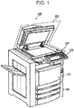
- Fig. 1 is a schematic diagram of an image processing apparatus 100 according to the embodiment.
- the image processing apparatus 100 is an apparatus which forms an image on a sheet, such as a multi-functional peripheral.
- the image processing apparatus 100 also can be an apparatus which decolors an image on a sheet formed with a decolorable toner by applying heat, such as a decoloring apparatus.
- a decoloring apparatus such as a decoloring apparatus.
- the image processing apparatus 100 is the multi-functional peripheral
- the image processing apparatus 100 includes a fixing section having the heat generating element therein.
- the heat generating element is provided in a decoloring section.
- the image processing apparatus 100 includes a display 110, a control panel 120, a printer 130, a sheet housing section 140 and an image reading section 200.
- the image processing apparatus 100 forms an image on a sheet using a toner.
- the sheet is, for example, a paper or a label paper. Any sheet type recording medium can be used for the image formation as long as the image processing apparatus 100 can form an image on a surface thereof.
- the display 110 is an image display device such as a liquid crystal display, an organic EL (Electro Luminescence) display and the like.
- the display 110 displays various information on the image processing apparatus 100.
- the sheet housing section 140 houses the sheet subjected to the image formation by the printer 130.
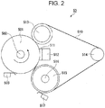
- Fig. 2 is a schematic diagram of a fixing section 50 included in the printer 130.
- the fixing section 50 includes a heat roller 501, a heater lamp 502, a thermistor 503, a pressure belt 510, a pressure pad 511, a pad holder 512, a pressure roller 513, a tension roller 514, a belt heating roller 515, a pressure belt lamp 516, and a pressure thermistor 517.
- the heat roller 501 is a fixing member formed into a cylindrical shape.
- the heater lamp 502 is arranged inside the heat roller 501.
- the heater lamp 502 is a halogen lamp, for example.
- the heater lamp 502 includes one or a plurality of lamps 523.
- the heater lamp 502 heats the heat roller 501 as the lamp 523 generates heat.
- the lamp 523 is described later.
- the thermistor 503 measures a surface temperature of the heat roller 501.
- the pressure pad 511 is supported in a state of sandwiching the pressure belt 510 in collaboration with the heat roller 501.
- the pad holder 512 holds the pressure pad 511 in the state that the pressure pad 511 is pressed toward the heat roller 501.
- the pressure roller 513 is arranged at the downstream side of the fixing nip portion in a conveyance direction of the sheet.
- the pressure roller 513 enables the pressure belt 510 to be pressure-contacted with the heat roller 501 in collaboration with the tension roller 514 and the belt heating roller 515.
- An exit of the fixing nip portion is formed along the pressure roller 513.
- the tension roller 514 is arranged on the inner side of the pressure belt 510 at a position away from the pressure roller 513 and the belt heating roller 515 to apply tension to the pressure belt 510.
- the belt heating roller 515 is arranged at the upstream side of the fixing nip portion in a conveyance direction of the sheet.
- the belt heating roller 515 is formed into a hollow cylindrical shape.
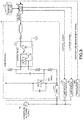
- a triac 522 is turned on at a next zero-cross timing of a waveform of the commercial AC power supply 70, and the electric power is supplied from the commercial AC power supply 70 to the lamp 523. If the control signal indicating OFF is output from the controller 60, the triac 522 is turned off at the next zero-crossing timing of the waveform of the commercial AC power supply 70, and the electric power supply from the commercial AC power supply 70 to the lamp 523 is stopped.
- a temperature measurement signal output from the thermistor 503 is input to the controller 60.
- the temperature measurement signal indicates the result of measurement of a temperature of the vicinity of the outer peripheral surface of the heat roller 501 by the thermistor 503.
- the controller 60 determines a duty ratio of the lamp 523 based on the measurement result by the thermistor 503. For example, the measurement result of the temperature and the duty ratio of each lamp 523 are associated with each other in advance, and the controller 60 determines the duty ratio according to the measurement result based on the association.
- the controller 60 then outputs the control signal indicating ON or OFF to the control circuit based on the control pattern according to the determined duty ratio.
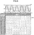
- Fig. 4 is a wave form chart and a table of the basic control pattern by the controller 60.
- a reference numeral 901 indicates a specific example of the waveform of the commercial AC power supply 70.
- a reference numeral 902 indicates a table showing a specific example of the basic control pattern by the controller 60.
- a time period corresponding to five periods of the commercial AC power supply 70 is equivalent to one period (hereinafter, referred to as a "pattern period") of the basic control pattern.
- One basic control pattern includes plural (for example, 10) steps.
- the number of steps included in one basic control pattern is 10. Therefore, in the example in Fig.
- the controller 60 controls ON and OFF of each lamp 523 so that the positive and negative polarities of a power supply current flowing from the commercial AC power supply 70 become more symmetrical.
- the controller 60 performs the control of ON and OFF of the lamp 523 in such a manner that the number of times of ON in the positive polarity and the number of times of ON in the negative polarity are closer.
- the controller 60 performs control in such a manner that a total value of the number of times of turning ON in the positive polarity in each lamp 523 and a total value of the number of times of turning ON in the negative polarity in each lamp 523 are closer.
- the controller 60 may perform control by multiplying the number of times by a weighting factor corresponding to the magnitude of the output.
- the controller 60 performs control in such a manner that a total value of the number of times of turning ON in the positive polarity and a total value of the number of times of turning ON in the negative polarity are closer.
- the controller 60 controls ON and OFF of each lamp 523 based on the control pattern table stored in the storage section 61 and the duty ratio of each lamp 523.
- the storage section 61 stores a value indicating ON or OFF at each step of each lamp 523 in association with the combination of the duty ratio of each lamp 523. For example, if the heater lamp 502 includes three lamps 523, the storage section 61 stores the control pattern table for each lamp 523 for the combination of the duty ratios of the three lamps 523.
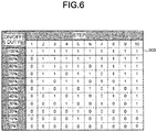
- Fig. 6 shows a specific example of a control pattern table 903 stored in the storage section 61.
- the storage section 61 stores the control pattern table as shown in Fig.
- the controller 60 reads out the control pattern table 903 of each lamp 523 according to the combination of the determined duty ratios from the storage section 61.
- the controller 60 controls ON and OFF of each lamp 523 at each step according to the control pattern table read by the controller 60.
- the control pattern table is generated by, for example, the following method which may be executed by, for example, an apparatus that performs pre-processing (for example, a computer).
- the pre-processing apparatus acquires a plurality of evaluation values relating to a plurality of control patterns.
- the plurality of the control patterns is ON and OFF control patterns realized by adding a predetermined change to the basic control pattern (refer to Fig. 4 or Fig. 5 ).
- a pattern in which all the lamps 523 are controlled according to the basic control pattern without any changes is one control pattern.
- a pattern in which a part of lamps 523 among the plurality of lamps 523 is controlled by shifting (delaying or advancing) by a half wave length from the basic control pattern is one control pattern.
- a lamp 523 of 600 watts The control of a lamp 523 of 600 watts, a lamp 523 of 600 watts, and a lamp 523 of 300 watts is described as a specific example.
- two lamps of 600 watts are called a first lamp and a second lamp, respectively, and the lamp of 300 watts is called a third lamp.
- the controller 60 may use the following four control patterns for the control of ON and OFF of the lamp 523.
- the pre-processing apparatus calculates the evaluation value in each control pattern.
- the evaluation value is a value of an index indicating whether the positive and negative polarities of the power supply current flowing from the commercial AC power supply 70 become nearly symmetrical if the control is performed according to the control pattern.
- the evaluation value relates to a polarity bias of the power supply current flowing from the commercial AC power supply 70.
- the evaluation value includes, for example, the following plural values.
- the pre-processing apparatus may select candidates in the order of the first rule, the second rule and the third rule, and may select that candidate at the time of being limited to one candidate as the control pattern.
- a weighting factor of the first lamp and the second lamp is set to "2" and a weighting factor of the third lamp is set to "1".
- the ratio of the output of each lamp may be used as the weighting factor.
- the candidates are not limited to one, and the third control pattern and the fourth control pattern remain as candidates.
- the pre-processing apparatus may select either the third control pattern or the fourth control pattern.
- the third control pattern may be selected based on the predetermined rule (a priority is higher in the order from the first to the fourth).
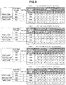
- Fig. 8 is a diagram of each control pattern table in the second application example.
- the control is performed based on the basic control pattern in Fig. 4 .
- the first lamp is controlled at the duty ratio of 80%, the second lamp at the duty ratio of 20%, and the third lamp at the duty ratio of 50%.
- the reference evaluation values (A) in the first control pattern to the fourth control pattern are as shown in the table in Fig. 8 .
- the first evaluation value (B), the second evaluation value (C), and the third evaluation value (D) in each control pattern are as follows.
- the candidate is limited to the third control pattern only, at the time the determination is made up to the third rule. Therefore, the pre-processing apparatus selects the third control pattern.
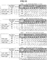
- Fig. 9 is a diagram of each control pattern table in the third application example.
- the control is performed based on the basic control pattern in Fig. 4 .
- the first lamp is controlled at the duty ratio of 70%, the second lamp at the duty ratio of 30%, and the third lamp at the duty ratio of 60%, respectively.
- the reference evaluation values (A) in the first control pattern to the fourth control pattern are as shown in the table in Fig. 9 .
- the first evaluation value (B), the second evaluation value (C), and the third evaluation value (D) in each control pattern are as follows.
- the candidate is limited to the second control pattern only, at the time the determination is made up to the second rule. Therefore, the pre-processing apparatus selects the second control pattern.
- Fig. 11 is a diagram of each control pattern table in the fifth application example.
- the control is performed based on the basic control pattern in Fig. 5 .
- the first lamp is controlled at the duty ratio of 70%, the second lamp at the duty ratio of 70%, and the third lamp at the duty ratio of 20%, respectively.
- the reference evaluation values (A) in the first control pattern to the fourth control pattern are as shown in the table in Fig. 11 .
- the first evaluation value (B), the second evaluation value (C), and the third evaluation value (D) in each control pattern are as follows.
- the candidate is not limited to one, and the second control pattern and the third control pattern remain as candidates.
- the pre-processing apparatus may select either the second control pattern or the third control pattern.
- the second control pattern may be selected based on the predetermined rule (the priority is higher in the order from the first to the fourth).
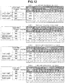
- Fig. 12 is a diagram of each control pattern table in the sixth application example.
- the control is performed based on the basic control pattern in Fig. 5 .
- the first lamp is controlled at the duty ratio of 70%, the second lamp at the duty ratio of 30% and the third lamp at the duty ratio of 50%, respectively.
- the reference evaluation values (A) in the first control pattern to the fourth control pattern are as shown in the table in Fig. 12 .
- the first evaluation value (B), the second evaluation value (C), and the third evaluation value (D) in each control pattern are as follows.
- the candidate is limited to the second control pattern only, at the time the determination is made up to the first rule. Therefore, the pre-processing apparatus selects the second control pattern.
Landscapes
- Physics & Mathematics (AREA)
- General Physics & Mathematics (AREA)
- Engineering & Computer Science (AREA)
- Microelectronics & Electronic Packaging (AREA)
- Human Computer Interaction (AREA)
- Fixing For Electrophotography (AREA)
- Control Or Security For Electrophotography (AREA)
- Control Of Resistance Heating (AREA)
- Control Of Temperature (AREA)
Applications Claiming Priority (1)
| Application Number | Priority Date | Filing Date | Title |
|---|---|---|---|
| JP2017140403A JP7000057B2 (ja) | 2017-07-19 | 2017-07-19 | 画像処理装置 |
Publications (1)
| Publication Number | Publication Date |
|---|---|
| EP3432078A1 true EP3432078A1 (de) | 2019-01-23 |
Family
ID=63014309
Family Applications (1)
| Application Number | Title | Priority Date | Filing Date |
|---|---|---|---|
| EP18182187.7A Withdrawn EP3432078A1 (de) | 2017-07-19 | 2018-07-06 | Bildverarbeitungsvorrichtung |
Country Status (4)
| Country | Link |
|---|---|
| US (1) | US10209653B2 (de) |
| EP (1) | EP3432078A1 (de) |
| JP (1) | JP7000057B2 (de) |
| CN (1) | CN109283816B (de) |
Citations (5)
| Publication number | Priority date | Publication date | Assignee | Title |
|---|---|---|---|---|
| EP0797130A2 (de) * | 1996-03-21 | 1997-09-24 | Canon Kabushiki Kaisha | Heizgerät für ein Bild |
| US20060204266A1 (en) * | 2005-03-10 | 2006-09-14 | Oki Data Corporation | Image recording apparatus |
| US20100239301A1 (en) * | 2009-03-18 | 2010-09-23 | Eiji Nemoto | Heater control with varying control cycle and lighting pattern |
| EP3109710A1 (de) * | 2015-06-23 | 2016-12-28 | Oki Data Corporation | Netzteileinheit und bilderzeugungsvorrichtung |
| US20170090360A1 (en) * | 2015-09-25 | 2017-03-30 | Kabushiki Kaisha Toshiba | Fixing device and image forming apparatus |
Family Cites Families (13)
| Publication number | Priority date | Publication date | Assignee | Title |
|---|---|---|---|---|
| JPH09258598A (ja) * | 1996-03-21 | 1997-10-03 | Canon Inc | 定着装置 |
| JP2005195640A (ja) | 2003-12-26 | 2005-07-21 | Canon Finetech Inc | 定着ヒータ制御方法および画像形成装置 |
| JP5305982B2 (ja) * | 2008-03-07 | 2013-10-02 | キヤノン株式会社 | 通電制御装置及び画像形成装置 |
| US8213822B2 (en) * | 2008-12-30 | 2012-07-03 | Lexmark International, Inc. | Power control for a printer fuser |
| JP5471618B2 (ja) * | 2010-03-05 | 2014-04-16 | 株式会社リコー | ヒータ制御装置、画像形成装置、ヒータ制御方法およびプログラム |
| US8639145B2 (en) * | 2010-11-03 | 2014-01-28 | Kabushiki Kaisha Toshiba | Image forming apparatus and method |
| JP6347586B2 (ja) * | 2013-10-02 | 2018-06-27 | キヤノン株式会社 | 画像形成装置 |
| JP6064931B2 (ja) * | 2014-03-19 | 2017-01-25 | コニカミノルタ株式会社 | 定着装置及び画像形成装置 |
| JP6070618B2 (ja) * | 2014-04-03 | 2017-02-01 | コニカミノルタ株式会社 | 定着装置および画像形成装置 |
| JP6548446B2 (ja) | 2015-05-08 | 2019-07-24 | キヤノン株式会社 | 定着装置 |
| JP6172208B2 (ja) * | 2015-05-08 | 2017-08-02 | コニカミノルタ株式会社 | 画像形成装置 |
| JP6288031B2 (ja) * | 2015-10-01 | 2018-03-07 | コニカミノルタ株式会社 | 定着装置及び画像形成装置 |
| JP6414039B2 (ja) * | 2015-12-11 | 2018-10-31 | コニカミノルタ株式会社 | 画像形成装置 |
-
2017
- 2017-07-19 JP JP2017140403A patent/JP7000057B2/ja active Active
-
2018
- 2018-03-22 US US15/928,381 patent/US10209653B2/en active Active
- 2018-05-24 CN CN201810505674.5A patent/CN109283816B/zh active Active
- 2018-07-06 EP EP18182187.7A patent/EP3432078A1/de not_active Withdrawn
Patent Citations (5)
| Publication number | Priority date | Publication date | Assignee | Title |
|---|---|---|---|---|
| EP0797130A2 (de) * | 1996-03-21 | 1997-09-24 | Canon Kabushiki Kaisha | Heizgerät für ein Bild |
| US20060204266A1 (en) * | 2005-03-10 | 2006-09-14 | Oki Data Corporation | Image recording apparatus |
| US20100239301A1 (en) * | 2009-03-18 | 2010-09-23 | Eiji Nemoto | Heater control with varying control cycle and lighting pattern |
| EP3109710A1 (de) * | 2015-06-23 | 2016-12-28 | Oki Data Corporation | Netzteileinheit und bilderzeugungsvorrichtung |
| US20170090360A1 (en) * | 2015-09-25 | 2017-03-30 | Kabushiki Kaisha Toshiba | Fixing device and image forming apparatus |
Also Published As
| Publication number | Publication date |
|---|---|
| JP2019020632A (ja) | 2019-02-07 |
| US20190025741A1 (en) | 2019-01-24 |
| US10209653B2 (en) | 2019-02-19 |
| JP7000057B2 (ja) | 2022-01-19 |
| CN109283816B (zh) | 2022-09-20 |
| CN109283816A (zh) | 2019-01-29 |
Similar Documents
| Publication | Publication Date | Title |
|---|---|---|
| US8494383B2 (en) | Image forming apparatus controlling power from a commercial AC power supply to a heater and detecting current flowing in a power supply path from the commercial AC power supply to the heater | |
| JP5305982B2 (ja) | 通電制御装置及び画像形成装置 | |
| JP4980165B2 (ja) | 画像形成装置及び電力制御方法 | |
| US8953964B2 (en) | Image forming apparatus and method of controlling fusing temperature of the same | |
| US9207607B2 (en) | Image forming apparatus capable of accurately estimating power consumption level | |
| JP6304131B2 (ja) | 定着装置及び画像形成装置 | |
| JP6589322B2 (ja) | 電源装置、画像形成装置、および電源装置の制御方法 | |
| JP4533054B2 (ja) | 定着装置 | |
| US10209653B2 (en) | Image processing apparatus | |
| JP2016161783A (ja) | 電源装置、画像形成装置、および電源装置の制御方法 | |
| JP7694632B2 (ja) | 画像形成装置、ヒータの制御方法およびヒータの制御プログラム | |
| CN114063415B (zh) | 图像形成装置 | |
| US20170082959A1 (en) | Fixing apparatus and image forming apparatus | |
| JP2008070686A (ja) | 定着装置及び画像形成装置 | |
| JP2014119696A (ja) | 画像形成装置 | |
| JP5640103B2 (ja) | 定着装置および画像形成装置 | |
| US10012931B2 (en) | Image forming apparatus, method for controlling fixing device and storage medium | |
| US20190196388A1 (en) | Fixing apparatus, image forming apparatus, and fixing apparatus control method | |
| JP2016040595A (ja) | 定着装置及び画像形成装置 | |
| US20190072886A1 (en) | Image processing apparatus with heating apparatus | |
| JP2012088443A (ja) | 画像形成装置 | |
| JP2007004040A (ja) | 画像形成装置 | |
| JP5070736B2 (ja) | 定着装置及びそれを用いた画像形成装置 | |
| JP2007328164A (ja) | 定着装置及びそれを用いた画像形成装置 | |
| JP2018189718A (ja) | 定着装置、及び画像形成装置 |
Legal Events
| Date | Code | Title | Description |
|---|---|---|---|
| PUAI | Public reference made under article 153(3) epc to a published international application that has entered the european phase |
Free format text: ORIGINAL CODE: 0009012 |
|
| STAA | Information on the status of an ep patent application or granted ep patent |
Free format text: STATUS: THE APPLICATION HAS BEEN PUBLISHED |
|
| AK | Designated contracting states |
Kind code of ref document: A1 Designated state(s): AL AT BE BG CH CY CZ DE DK EE ES FI FR GB GR HR HU IE IS IT LI LT LU LV MC MK MT NL NO PL PT RO RS SE SI SK SM TR |
|
| AX | Request for extension of the european patent |
Extension state: BA ME |
|
| STAA | Information on the status of an ep patent application or granted ep patent |
Free format text: STATUS: THE APPLICATION IS DEEMED TO BE WITHDRAWN |
|
| 18D | Application deemed to be withdrawn |
Effective date: 20190724 |