EP3432092B1 - Procédé et dispositif de commande pour maison intelligente - Google Patents
Procédé et dispositif de commande pour maison intelligente Download PDFInfo
- Publication number
- EP3432092B1 EP3432092B1 EP17765879.6A EP17765879A EP3432092B1 EP 3432092 B1 EP3432092 B1 EP 3432092B1 EP 17765879 A EP17765879 A EP 17765879A EP 3432092 B1 EP3432092 B1 EP 3432092B1
- Authority
- EP
- European Patent Office
- Prior art keywords
- smart home
- state information
- terminal
- target
- application
- Prior art date
- Legal status (The legal status is an assumption and is not a legal conclusion. Google has not performed a legal analysis and makes no representation as to the accuracy of the status listed.)
- Active
Links
Images



Classifications
-
- G—PHYSICS
- G06—COMPUTING OR CALCULATING; COUNTING
- G06F—ELECTRIC DIGITAL DATA PROCESSING
- G06F3/00—Input arrangements for transferring data to be processed into a form capable of being handled by the computer; Output arrangements for transferring data from processing unit to output unit, e.g. interface arrangements
- G06F3/01—Input arrangements or combined input and output arrangements for interaction between user and computer
- G06F3/048—Interaction techniques based on graphical user interfaces [GUI]
- G06F3/0484—Interaction techniques based on graphical user interfaces [GUI] for the control of specific functions or operations, e.g. selecting or manipulating an object, an image or a displayed text element, setting a parameter value or selecting a range
-
- F—MECHANICAL ENGINEERING; LIGHTING; HEATING; WEAPONS; BLASTING
- F24—HEATING; RANGES; VENTILATING
- F24F—AIR-CONDITIONING; AIR-HUMIDIFICATION; VENTILATION; USE OF AIR CURRENTS FOR SCREENING
- F24F11/00—Control or safety arrangements
- F24F11/30—Control or safety arrangements for purposes related to the operation of the system, e.g. for safety or monitoring
-
- G—PHYSICS
- G01—MEASURING; TESTING
- G01W—METEOROLOGY
- G01W1/00—Meteorology
- G01W1/02—Instruments for indicating weather conditions by measuring two or more variables, e.g. humidity, pressure, temperature, cloud cover or wind speed
- G01W1/06—Instruments for indicating weather conditions by measuring two or more variables, e.g. humidity, pressure, temperature, cloud cover or wind speed giving a combined indication of weather conditions
-
- G—PHYSICS
- G05—CONTROLLING; REGULATING
- G05B—CONTROL OR REGULATING SYSTEMS IN GENERAL; FUNCTIONAL ELEMENTS OF SUCH SYSTEMS; MONITORING OR TESTING ARRANGEMENTS FOR SUCH SYSTEMS OR ELEMENTS
- G05B15/00—Systems controlled by a computer
- G05B15/02—Systems controlled by a computer electric
-
- G—PHYSICS
- G05—CONTROLLING; REGULATING
- G05B—CONTROL OR REGULATING SYSTEMS IN GENERAL; FUNCTIONAL ELEMENTS OF SUCH SYSTEMS; MONITORING OR TESTING ARRANGEMENTS FOR SUCH SYSTEMS OR ELEMENTS
- G05B19/00—Program-control systems
- G05B19/02—Program-control systems electric
- G05B19/418—Total factory control, i.e. centrally controlling a plurality of machines, e.g. direct or distributed numerical control [DNC], flexible manufacturing systems [FMS], integrated manufacturing systems [IMS] or computer integrated manufacturing [CIM]
-
- H—ELECTRICITY
- H04—ELECTRIC COMMUNICATION TECHNIQUE
- H04L—TRANSMISSION OF DIGITAL INFORMATION, e.g. TELEGRAPHIC COMMUNICATION
- H04L12/00—Data switching networks
- H04L12/28—Data switching networks characterised by path configuration, e.g. LAN [Local Area Networks] or WAN [Wide Area Networks]
- H04L12/2803—Home automation networks
-
- F—MECHANICAL ENGINEERING; LIGHTING; HEATING; WEAPONS; BLASTING
- F24—HEATING; RANGES; VENTILATING
- F24F—AIR-CONDITIONING; AIR-HUMIDIFICATION; VENTILATION; USE OF AIR CURRENTS FOR SCREENING
- F24F2130/00—Control inputs relating to environmental factors not covered by group F24F2110/00
- F24F2130/10—Weather information or forecasts
-
- G—PHYSICS
- G01—MEASURING; TESTING
- G01W—METEOROLOGY
- G01W1/00—Meteorology
- G01W2001/006—Main server receiving weather information from several sub-stations
-
- G—PHYSICS
- G01—MEASURING; TESTING
- G01W—METEOROLOGY
- G01W2203/00—Real-time site-specific personalized weather information, e.g. nowcasting
-
- G—PHYSICS
- G05—CONTROLLING; REGULATING
- G05B—CONTROL OR REGULATING SYSTEMS IN GENERAL; FUNCTIONAL ELEMENTS OF SUCH SYSTEMS; MONITORING OR TESTING ARRANGEMENTS FOR SUCH SYSTEMS OR ELEMENTS
- G05B2219/00—Program-control systems
- G05B2219/20—Pc systems
- G05B2219/26—Pc applications
- G05B2219/2642—Domotique, domestic, home control, automation, smart house
-
- Y—GENERAL TAGGING OF NEW TECHNOLOGICAL DEVELOPMENTS; GENERAL TAGGING OF CROSS-SECTIONAL TECHNOLOGIES SPANNING OVER SEVERAL SECTIONS OF THE IPC; TECHNICAL SUBJECTS COVERED BY FORMER USPC CROSS-REFERENCE ART COLLECTIONS [XRACs] AND DIGESTS
- Y02—TECHNOLOGIES OR APPLICATIONS FOR MITIGATION OR ADAPTATION AGAINST CLIMATE CHANGE
- Y02P—CLIMATE CHANGE MITIGATION TECHNOLOGIES IN THE PRODUCTION OR PROCESSING OF GOODS
- Y02P90/00—Enabling technologies with a potential contribution to greenhouse gas [GHG] emissions mitigation
- Y02P90/02—Total factory control, e.g. smart factories, flexible manufacturing systems [FMS] or integrated manufacturing systems [IMS]
Definitions
- the present invention relates to the field of smart control, and more particularly to a control method and apparatus for a smart home.
- a patent document with publication number KR20120016739 discloses that the method for controlling the air-conditional in which the invention corresponds to the change of the power rates and which is controlled and such air-conditioner is performed.
- the invention provides the air-conditioner consisting of the smart control device comprising: the smart control unit which includes the outdoor unit performing air and heat exchange of the outdoor, the indoor unit , and the second operation mode; and selectively performs the first operation mode or the second operation mode based on the comparison result with the first and second power information and predetermined reference value; the indoor unit is installed within the indoor space; and supplies to the cold air, and the air of the hot air or the room temperature within the indoor space; and as to the second operation mode, the amount of power saving is less than those of the first operation mode while controlling the air-conditioner based on the first operation mode and the second power information controlling the air-conditioner based on the second communication unit and the first power information receiving the second power information based on the first communication unit receiving the first power information about the electricity of being supplied in the systematic power, and
- a patent document with publication number WO2011/100427A2 discloses a method and apparatus for controlling climate within a building.
- the apparatus comprises a smart climate unit for (i) obtaining distributed generator (DG) information pertaining to operation of a DG that generates power for the building, and (ii) controlling at least one climate condition within the building based on at least one of the DG information, local input, or remote input.
- DG distributed generator
- a patent document with publication number CN103032935A provides an air-conditioner control terminal which can perform various settings, such as wind direction, wind speed, and the like of an air-conditioner, through simple and visualized operations.
- the air-conditioner control terminal comprise: a storage part which stores setting information to an air-conditioner body including wind direction and wind speed; a control part which displays an operation object image representing wind blown out from a unit of the air-conditioner body, that is, wind blowing, on a touch screen part, and stores the setting information that includes wind direction and wind speed and is changed by the operation of touching and moving of the operation object image in the storage part; and a communication part which sends the changed setting information to the air-conditioner body.
- a patent document with publication number US2012310418A1 provides Controllers for controlling heating, ventilating, air conditioning, and cooling (HVAC) systems.
- the controllers include graphical user interfaces for user adjustment of system settings.
- the graphical user interfaces may include slide bars for adjusting temperature set points.
- the graphical user interfaces may include selectable calendars for adjusting program schedules for the HVAC systems.
- the graphical user interfaces may include screens for adjusting a nightlight feature of the controller.
- the embodiment of the present invention provides a control method and apparatus for a smart home, intended to at least solve the technical problem in the conventional art of low control convenience of a smart home.
- an embodiment of a control method for a smart home is provided. It is to be noted that the steps illustrated in the flowchart of the drawings may be executed in a computer system such as a set of computer executable instructions, and although the logical order is shown in the flowchart, in some cases, the steps shown or described may be performed in an order different from the order herein.
- Fig. 1 is a flowchart of a control method for a smart home according to an embodiment of the present invention. As shown in Fig. 1 , the control method includes the steps as follows.
- weather information of a region where a terminal is located is acquired, and state information of a target smart home is acquired from a smart home application, wherein the smart home application is installed on the terminal.
- the state information of the target smart home and the weather information are synchronously displayed on a screen of the terminal.
- a trigger signal generated on the basis of the state information and the weather information is received.
- a control signal is generated on the basis of the trigger signal, wherein the control signal isto control an operation state of the target smart home by means of the smart home application.
- the terminal After acquiring weather information of a region where a terminal is located and acquiring state information of a target smart home from a smart home application, the terminal synchronously displays the acquired state information of the target smart home and the acquired weather information on a screen of the terminal, and when a trigger signal is received, an operation state of the target smart home can be controlled by means of the smart home application.
- the terminal synchronously displays the state information of the target smart home and the weather information, and quickly controls the operating state of the target smart home on the same page on the basis of the weather information.
- the present invention achieves the technical effects of quickly controlling a target smart home and improving the control convenience of a smart home, and solves the technical problem in the conventional art of low control convenience of a smart home.
- the terminal in the above embodiment is a mobile terminal, such as a mobile phone, a computer, or a remote controller.
- the smart home may include household devices such as an air conditioner, a dehumidifier, a humidifier, an air purifier, a washing machine, a range hood and so on.
- the smart home is connected to a smart home application and controlled by the smart home application.
- the state information of the smart home is used to indicate information such as the turn on and off of the smart home, an operation mode, and the state of various internal components.
- the state information of the smart home such as the air conditioner may include: information such as operating, a cooling mode, and a current indoor temperature 25°C.
- the weather information may include weather state information of a region where the terminal is located, such as air quality information, health value information, body temperature, comfort, temperature, humidity, and appropriate values.
- the terminal After receiving a trigger signal of a switch button on the screen of the terminal, the terminal sends a control signal to the smart home application, and control the smart home application to control an operating state of a target smart home bound to the application, and the operating state may include states such as turn on, turn off, and adjustment of an operating mode, an operating speed, voltage and current.
- the step of receiving a trigger signal generated on the basis of the state information and the weather information includes: receiving a trigger signal acting on a switch button, wherein switch buttons corresponding to the state information and the weather information are disposed in the screen of the terminal.
- the manner of acting on the switch button in the above embodiment may be single click, double click, slide, or the like.
- a preset region in the screen of the terminal includes a switch button for controlling turn on or off of the target smart home, a trigger signal acting on the switch button is received, and a control signal for controlling turn on or off of the target smart home is sent to the smart home application.
- a page of the weather application i.e., within the preset region on the screen of the terminal
- receives the trigger signal acting on the switch button and the turn on or off of the target smart home may be controlled through the smart home application.
- control method before acquiring state information of a target smart home from a smart home application, the control method further includes: determining the target smart home in a smart home list, wherein multiple smart homes are recorded in the smart home list, and each smart home in the multiple smart homes is associated with the smart home application.
- the target smart home in the smart home list is first determined, then the state information of the target smart home is acquired from the smart home application, the weather information and the state information of the target smart home are simultaneously displayed on the screen of the terminal, and the smart home is controlled according to the trigger signal.
- the target smart home in a display state needing to be synchronized is displayed by filtering out the invalid smart home state information, thereby improving the rate of information acquiring and achieving the effect of quickly and accurately acquiring the state information of the target smart home.
- the step of determining the target smart home in a smart home list includes: displaying an application page of a weather application on the screen of the terminal, a synchronous start button being disposed on the application page; if it is detected that the synchronous start button is pressed, generating a synchronous start instruction, the synchronous start instruction being used to acquire the smart home list of the smart home application; and determining the selected target smart home in the smart home list.
- the target smart home is determined from the list to acquire the state information of the target smart home.
- the weather information is acquired, the state information of the target smart home and the weather information are synchronously displayed on the screen, and the operating state of the target smart home is controlled after the control signal is received.
- the target smart home is determined through the smart home list that can be acquired through a synchronous start button on the weather application page, thereby achieving the effect of simplifying the operation steps of the target smart home.
- the step of determining the target smart home in a smart home list includes: after the weather application is started, acquiring a smart home list of the smart home application; and determining multiple smart homes recorded in the smart home list as the target smart homes.
- all smart homes bound to the smart home application may be automatically determined as the target smart homes, that is, the function of manually synchronizing devices by a user can be cancelled.
- the connected devices such as the air conditioner, the dehumidifier, the humidifier and the air purifier in the smart home may be automatically synchronized to the weather module.
- the area occupied by the weather module will be relatively large, and the proportion in the weather application will be too large. The convenience brought by the automatic connection to control the smart home will be weakened.
- the step of synchronously displaying the state information of the target smart home and the weather information on a screen of the terminal includes: displaying the state information in a first region on the screen of the terminal, and displaying the weather information in a second region on the screen of the terminal.
- the state information of the target smart home and the weather information are separately and synchronously displayed in the first region and the second region on the screen of the terminal, so as to achieve a comprehensive understanding of the weather information and the operating state of the smart home by a terminal operator.
- a management button corresponding to the target smart home is also disposed in the first region, and after synchronously displaying the state information of the target smart home and the weather information on a screen of the terminal, the control method further includes: if it is detected that the management button is pressed, jumping to a management binding home page, wherein the management binding home page is provided with a binding management button for modifying a synchronization state of the target smart home, the modification including initiating synchronization or canceling synchronization; and when it is detected that the binding management button is pressed, executing an operation of modifying the synchronization state of the target smart home which indicated by the binding management button.
- the first region on the screen of the terminal in the above embodiment can record the state information of the smart home, and can also be provided with a management button corresponding to the target smart home.
- a management button corresponding to the target smart home.
- binding management for the synchronization state of the smart home can be realized. That is, the synchronous display of the state information of the target smart home and the weather information may be initiated through the management button, and the synchronous display of the state information of the target smart home and the weather information may be cancelled through the management button.
- the binding state of the target smart home may be flexibly controlled, and the comfort of user experience can be improved.
- the step of receiving a trigger signal generated on the basis of the state information and the weather information includes: when it is detected that the state information of the target smart home is operated, determining that the trigger signal generated in response to the operation is received; and generating a control signal on the basis of the trigger signal includes: entering a device page of the target smart home in response to the trigger signal , wherein the device page is provided with multiple working mode buttons; and generating the control signals corresponding to the working mode buttons when the working mode buttons are triggered.
- a device page of the target smart home may be entered, and the working mode of the target smart home is more deeply controlled or adjusted through a working mode button on the device page.
- a management binding electrical appliance page may be opened by the management button to implement rapid change or cancellation of the binding state of the target smart home, thereby achieving the effect of flexible and efficient management of the target smart home.
- the operations of the above embodiment may include single click, double click, pressing, and slide, etc.
- the above working mode may include various working modes of different smart homes.
- the above working mode may include a cooling mode, a heating mode, a ventilation mode, a dehumidification mode, an automatic mode, and the like.
- the target smart home is an air purifier
- the above working mode may include an automatic mode, a large air volume mode, a small air volume mode, and the like.
- the control method before acquiring weather information of a region where a terminal is located and acquiring the state information of a target smart home from a smart home application, the control method includes: establishing a connection between a weather application and a smart home application, wherein the smart home application is an application program for controlling the target smart home, and the weather application is an application program for detecting and displaying the weather information.
- the weather application and the smart home application are connected, and the weather information and the operating state of the target smart home are displayed together, thereby achieving the effects of interconnection of two different application programs, information synchronization between the two different applications, and quick connection and operation.
- a mobile phone i.e., the terminal mentioned above
- a weather application and a smart home application may be installed on the mobile phone.
- the weather application is used to detect and display weather information of a city where the mobile phone is located, and the smart home application may control an operating state such as turn on or off of a target smart home.
- the weather application first establishes a connection with the smart home application. After the connection is established, the weather application page of the mobile phone may synchronously display the weather information and the operating state information of the target smart home, the mobile phone or the user of the mobile phone may control the operating state of the target smart home according to the weather information.
- the control method is implemented based on a weather application operation page. Specifically, the smart home application connected with the weather application is used to control the target smart home.
- the user may quickly turn on or off corresponding home appliances according to the weather information, thereby improving the convenience of the user operation.
- the preset region includes a device list of the target smart home
- the step of receiving the trigger signal in the preset region on the screen of the terminal includes: receiving a trigger signal acting on the device list
- the step of sending a control signal to the smart home application includes: sending a control signal for controlling a preset module page in the weather application, wherein the preset module page is a module for controlling the target smart home.
- the preset module page in the weather application (such as a control page of the corresponding target smart home in the smart home application) may be opened by a trigger signal of the device list in the preset region on the screen of the terminal, so as to achieve a more complicated operation on the selected target smart home, thereby achieving the technical effect of more comprehensively and effectively controlling the target smart home.
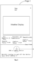
- Page 1 in Fig. 2 is a page where no smart home is added
- Page 2 in Fig. 3 is a page for managing and binding a smart home
- Page 3 in Fig. 4 is a page added with a smart home.
- Page 1 shown in Fig. 2 is an application page of a weather application.
- the page of the weather application includes the name of a region where the terminal is located, such as "Zhuhai” in Fig. 2 .
- the following is a "Weather Display” sub-page for displaying weather conditions, including weather conditions such as "Air Quality Poor 125", “Health Value 0-100”, “Sensible Temperature 28°C”, “Comfort Value 17-24”, “Humidity 90%”, and “Appropriate value 50-60".
- the above display region of the weather information about the region and weather conditions is the second region in the above embodiment, and the bottom part is the region of the smart home module, that is, the first region in the above embodiment, for "Add a common device” and “Quickly turn on and off the device here after adding it".
- the circle with a cross in the middle of Page 1 in Fig. 2 indicates a synchronous start button in the above embodiment. If it is detected that the synchronous start button is pressed, a synchronous start instruction is generated, the synchronous start instruction being used to acquire a smart home list of the smart home application.
- the smart home list is shown as Page 2 in Fig. 3 .
- the arrow in Fig. 2 indicates a flow direction, that is, after pressing the synchronous start button, Page 1 will jump to Page 2 shown in Fig. 3 .
- Page 2 of Fig. 3 is a management binding electrical appliance page, which includes a smart home list, and specifically includes a page title “Management” and "Bound with a smart home device”. It specifically includes the following devices: “Air Conditioner” located in “Master Bedroom”, “Air Conditioner” located in “Living Room”, “Air Conditioner 2" located in “Living Room”, “Air Conditioner” located in “Study Room”, “Air Purifier” located in “Living Room”, “Humidifier” located in “Bedroom”, and “Humidifier 2" located in “Bedroom”.
- the right side of the line where these devices are located shows the binding state of the device (i.e., smart home) and the smart home application, mainly including "Synchronized”, “Cancel” and “Synchronize to Weather".
- the arrow in Fig. 3 indicates that after operating the "Synchronize to Weather" button, Page 2 will jump to Page 3 as shown in Fig. 4 .
- Page 3 of Fig. 4 is a page added with a smart home.
- Page 3 is basically the same as the display of the second region in Page 1, except that the region of the bottommost smart home module in Page 3 (i.e., the first region) changes to: display a smart home picture, a smart home name, a location, an operating mode state, and a button for controlling on and off.
- the page of the smart home module may include: "Bedroom, Air Conditioner, 25°C, Cooling, Operating" and “Off” button, which indicates that the air conditioner in the bedroom is in a cooling operation with a cooling temperature of 25°C and the air conditioner may be turned off by a corresponding "Off” button.
- the page of the smart home module may also include "Living Room, Purifier, Wind speed: Automatic, Not On” and "On” button, which indicates that the wind speed of the purifier located in the living room is automatic in the non-on state and the purifier may be controlled to be turned on by the "On” button, wherein the smart home in the page of the smart home module is a device that is bound to the smart home application, as shown in Page 2, that is, the bound target smart home.
- the first region in Page 3 is also provided with a management button corresponding to the target smart home, such as the "Management" button in Fig. 4 . If it is detected that the management button is pressed, it jumps to the management binding home page.
- the module is used for the first time (i.e., the smart home module in the weather application described above): no binding device is displayed, a user may click on a button for adding a device ("Add a Common Device” button in Page 1 of Fig. 2 , that is, a synchronous start button) to enter a management binding electrical appliance page (i.e., Page 2), which displays the devices such as an air conditioner, a dehumidifier, a humidifier and an air purifier having been connected to the smart home. Then, the button for synchronizing the device (“Synchronize to Weather" button in Page 2 of Fig. 3 ) may be selected, thereby being able to synchronize to the weather application.
- a button for adding a device (“Add a Common Device” button in Page 1 of Fig. 2 , that is, a synchronous start button) to enter a management binding electrical appliance page (i.e., Page 2), which displays the devices such as an air conditioner, a dehumidifier, a humidifier and
- this module When using this module again (i.e., the smart home module in the above weather application): it can display a device that the user has bound (such as "Air Conditioner” and “Purifier” in Page 3 of Fig. 4 ), and display the current state of the device synchronously.
- the user can quickly switch the device through the "On” and “Off” buttons, and can also click on the device list to quickly enter the smart home page of the device to achieve more complicated operating state adjustment.
- the user can click on the "Management” text (i.e., the Management button) in Page 3 in Fig. 4 to enter the management binding electrical appliance page to change or cancel the device synchronized to the weather.
- the operation of clicking the device list to enter the smart home page of the device may be canceled, and only the button function of quickly turning on and off the device is retained. But users who want to change the device mode need to open the smart home application for further control.
- the device may also keep open, but the information of the device will not be displayed again in the weather application, and the quick operation of turning on and off the device cannot be performed any longer.
- the device may also be switched off or on through the smart home application.
- a control apparatus for a smart home includes: an acquisition unit 20, a display unit 40, a receiving unit 60, and a generation unit 80.
- the acquisition unit 20 is configured to acquire weather information of a region where a terminal is located, and acquire the state information of a target smart home from a smart home application, the smart home application being installed on the terminal.
- the display unit 40 is configured to synchronously display the state information of the target smart home and the weather information on a screen of the terminal.
- the receiving unit 60 is configured to receive a trigger signal generated on the basis of the state information and the weather information.
- the generation unit 80 is configured to generate a control signal on the basis of the trigger signal, the control signal being used for controlling an operation state of the target smart home by means of the smart home application.
- the terminal After acquiring weather information of a region where a terminal is located and acquiring the state information of a target smart home from a smart home application, the terminal synchronously displays the acquired state information of the target smart home and the acquired weather information on a screen of the terminal, and when a trigger signal is received, an operation state of the target smart home can be controlled by means of the smart home application.
- the terminal may synchronously displays the state information of the target smart home and the weather information, and quickly controls the operating state of the target smart home on the same page on the basis of the weather information.
- the present invention achieves the technical effects of quickly controlling a target smart home and improving the control convenience of a smart home, and solves the technical problem in the conventional art of low control convenience of a smart home.
- the receiving unit 60 includes: a receiving module, configured to receive a trigger signal acting on a switch button, wherein switch buttons corresponding to the state information and the weather information are disposed in the screen of the terminal.
- a page of the weather application i.e., within the preset region on the screen of the terminal
- receives the trigger signal acting on the switch button and the turn on or off of the target smart home may be controlled through the smart home application.
- control apparatus further includes: a determination unit, configured to determine before acquiring state information of a target smart home from a smart home application, the target smart home in a smart home list, wherein multiple smart homes are recorded in the smart home list, and each smart home in the multiple smart homes is associated with the smart home application.
- a determination unit configured to determine before acquiring state information of a target smart home from a smart home application, the target smart home in a smart home list, wherein multiple smart homes are recorded in the smart home list, and each smart home in the multiple smart homes is associated with the smart home application.
- the target smart home in the smart home list is first determined, then the state information of the target smart home is acquired from the smart home application, the weather information and the state information of the target smart home are simultaneously displayed on the screen of the terminal, and the smart home is controlled according to the trigger signal.
- the target smart home in a display state needing to be synchronized is displayed by filtering out the invalid smart home state information, thereby improving the rate of information acquiring and achieving the effect of quickly and accurately acquiring the state information of the target smart home.
- the determination unit includes: a display module, configured to display an application page of a weather application on the screen of the terminal, a synchronous start button being disposed on the application page; an instruction generation module, configured to generate a synchronous start instruction, if it is detected that the synchronous start button is pressed, the synchronous start instruction being used to acquire the smart home list of the smart home application; and a first determination module, configured to determine the selected target smart home in the smart home list.
- the smart home list of the smart home application is acquired, and the target smart home is determined from the list to acquire the state information of the target smart home.
- the weather information is acquired, the state information of the target smart home and the weather information are synchronously displayed on the screen, and the operating state of the target smart home is controlled after the control signal is received.
- the smart home list may be acquired through a synchronous start button on the weather application page to determine the target smart home, thereby achieving the effect of simplifying the operation steps of the target smart home.
- the determination unit includes: an acquisition module, configured to acquire a smart home list of the smart home application after the weather application is started; and a second determination module, configured to determine multiple smart homes recorded in the smart home list as the target smart home.
- all smart homes bound to the smart home application may be automatically determined as the target smart home, that is, the function of manually synchronizing devices by a user may be cancelled.
- the connected devices such as the air conditioner, the dehumidifier, the humidifier and the air purifier in the smart home may be automatically synchronized to the weather module.
- the area occupied by the module will be relatively large, and the proportion in the weather application will be too large. The convenience brought by the automatic connection to control the smart home will be weakened.
- the display unit 40 includes: an information display module, configured to display the state information in a first region on the screen of the terminal, and display the weather information in a second region on the screen of the terminal.
- the state information of the target smart home and the weather information are separately and synchronously displayed in the first region and the second region on the screen of the terminal, so as to achieve a comprehensive understanding of the weather information and the operating state of the smart home by a terminal operator.
- a management button corresponding to the target smart home is also disposed in the first region, and the control apparatus further includes: a jumping module, configured to jump to a management binding home page if it is detected that the management button is pressed after synchronously displaying the state information of the target smart home and the weather information on a screen of the terminal, wherein the management binding home page is provided with a binding management button for modifying a synchronization state of the target smart home, the modification including initiating synchronization or canceling synchronization; and an execution module, configured to execute an operation of modifying the synchronization state of the target smart home that indicated by the binding management button, when it is detected that the binding management button is pressed, ,.
- a jumping module configured to jump to a management binding home page if it is detected that the management button is pressed after synchronously displaying the state information of the target smart home and the weather information on a screen of the terminal, wherein the management binding home page is provided with a binding management button for modifying a synchronization state of the target smart home
- the first region on the screen of the terminal in the above embodiment can record the state information of the smart home, and can also be provided with a management button corresponding to the target smart home.
- a management button corresponding to the target smart home.
- binding management for the synchronization state of the smart home can be realized. That is, the synchronous display of the state information of the target smart home and the weather information may be initiated through the management button, and the synchronous display of the state information of the target smart home and the weather information may be cancelled through the management button.
- the binding state of the target smart home may be flexibly controlled, and the user experience comfort is improved.
- the receiving unit 60 is configured to determine that the trigger signal generated in response to the operation is received, when it is detected that the state information of the target smart home is operated;
- the generation unit 80 includes: an entry module, configured to enter a device page of the target smart home in response to the trigger signal,, wherein the device page is provided with multiple working mode buttons; and a signal generation module, configured to generate the control signals corresponding to the working mode buttons, when the working mode buttons are triggered.
- a device page of the target smart home may be entered, and the working mode of the target smart home is more deeply controlled or adjusted through a working mode button on the device page.
- a management binding electrical appliance page may be opened by the management button to implement rapid change or cancellation of the binding state of the target smart home, thereby achieving the effect of flexible and efficient management of the target smart home.
- a user can manually cancel device synchronization between the weather application and the smart home application.
- the connected devices such as the air conditioner, the dehumidifier, the humidifier and the air purifier in the smart home may be automatically synchronized to the weather module.
- the area occupied by the module will be relatively large, and the proportion in the weather application will be too large. The convenience brought by the automatic connection to control the smart home will be weakened.
- the weather application is associated with the smart home application, the synchronized smart home is quickly turned on or off through the module in the weather application, and the operating state of the smart home is displayed.
- the user may quickly turn on or off corresponding home appliances according to the weather information, thereby improving the convenience of the user operation.
- division of the units may be division of logical functions, and there may be additional division modes during actual implementation.
- a plurality of units or components may be combined or integrated to another system, or some features may be omitted or may be not executed.
- displayed or discussed mutual coupling or direct coupling or communication connection may be performed via some interfaces, and indirect coupling or communication connection between units or modules may be in an electrical form or other forms.
- the units illustrated as separate parts may be or may not be physically separated.
- Parts for unit display may be or may not be physical units. That is, the parts may be located at a place or may be distributed on a plurality of units.
- the aims of the solutions of the embodiments may be achieved by selecting some or all units according to actual requirements.
- all function units in all embodiments of the present invention may be integrated in a processing unit, or each unit may exist separately and physically, or two or more units may be integrated in a unit.
- the integrated unit may be implemented in a hardware form or may be implemented in a software function unit form.
- the integrated unit may also be stored in a computer-readable storage medium.
- the computer software product is stored in a storage medium, including a plurality of instructions used to enable a computer device (which may be a personal computer, a server, a network device or the like) to execute all or part of the method in each embodiment of the present invention.
- the foregoing storage medium includes: various media capable of storing program codes such as a U disk, a Read-Only Memory (ROM), a Random Access Memory (RAM), a mobile hard disk, a magnetic disk or an optical disk.
Landscapes
- Engineering & Computer Science (AREA)
- General Engineering & Computer Science (AREA)
- Physics & Mathematics (AREA)
- General Physics & Mathematics (AREA)
- Automation & Control Theory (AREA)
- Manufacturing & Machinery (AREA)
- Quality & Reliability (AREA)
- Environmental & Geological Engineering (AREA)
- Theoretical Computer Science (AREA)
- Combustion & Propulsion (AREA)
- Chemical & Material Sciences (AREA)
- Mechanical Engineering (AREA)
- Ecology (AREA)
- Life Sciences & Earth Sciences (AREA)
- Environmental Sciences (AREA)
- Human Computer Interaction (AREA)
- Signal Processing (AREA)
- Biodiversity & Conservation Biology (AREA)
- Computer Networks & Wireless Communication (AREA)
- Atmospheric Sciences (AREA)
- Selective Calling Equipment (AREA)
- Telephonic Communication Services (AREA)
- User Interface Of Digital Computer (AREA)
- Management, Administration, Business Operations System, And Electronic Commerce (AREA)
Claims (12)
- Procédé de commande pour une maison connectée, caractérisé en ce qu'il comprend les étapes consistant à :acquérir des informations météorologiques d'une région où se trouve un terminal, et acquérir des informations d'état d'une maison connectée cible à partir d'une application de maison connectée installée sur le terminal, le terminal étant un terminal mobile ;afficher de manière synchrone les informations d'état de la maison connectée cible et les informations météorologiques sur un écran du terminal ;recevoir un signal de déclenchement généré sur la base des informations d'état et des informations météorologiques ; etgénérer, en fonction du signal de déclenchement, un signal de commande pour commander un état de fonctionnement de la maison connectée cible par l'intermédiaire de l'application de maison connectée,dans lequel les informations d'état de la maison connectée sont utilisées pour indiquer des informations qui comprennent au moins l'un des éléments suivants :une activation et une désactivation de la maison connectée, un mode de fonctionnement de la maison connectée et des états de divers composants internes de la maison connectée,les informations météorologiques sont des informations d'état météorologique d'une région où le terminal est situé,dans lequel l'affichage synchrone des informations d'état de la maison connectée cible et des informations météorologiques sur un écran du terminal comprend les étapes consistant à :afficher les informations d'état dans une première région sur l'écran du terminal, et afficher les informations météorologiques dans une seconde région sur l'écran du terminal,dans lequel un bouton de gestion correspondant à la maison connectée cible est également disposé dans la première région, et après l'affichage synchrone des informations d'état de la maison connectée cible et des informations météorologiques sur un écran du terminal, le procédé de commande comprend en outre les étapes consistant à :s'il est détecté que le bouton de gestion est enfoncé, passer à une page d'accueil de liaison de gestion, la page d'accueil de liaison de gestion étant pourvue d'un bouton de gestion de liaison pour modifier un état de synchronisation de la maison connectée cible, la modification comprenant le lancement d'une synchronisation ou l'annulation d'une synchronisation ; etlorsqu'il est détecté que le bouton de gestion de liaison est enfoncé, exécuter une opération, indiquée par le bouton de gestion de liaison, de modification de l'état de synchronisation de la maison connectée cible,dans lequel l'affichage synchrone des informations d'état de la maison connectée cible et des informations météorologiques est lancé via le bouton de gestion, et l'affichage synchrone des informations d'état de la maison connectée cible et des informations météorologiques est annulé via le bouton de gestion,la synchronisation de lancement est que l'affichage synchrone des informations d'état de la maison connectée cible et des informations météorologiques est lancé via le bouton de gestion, et la synchronisation d'annulation est que l'affichage synchrone des informations d'état de la maison connectée cible et des informations météorologiques est annulé via le bouton de gestion.
- Procédé de commande selon la revendication 1, dans lequel la réception d'un signal de déclenchement généré sur la base des informations d'état et des informations météorologiques comprend l'étape consistant à :
recevoir un signal de déclenchement qui est en réponse à l'action sur un bouton de commutation, des boutons de commutation correspondant aux informations d'état et aux informations météorologiques étant disposés dans l'écran du terminal. - Procédé de commande selon la revendication 1, dans lequel avant d'acquérir les informations d'état d'une maison connectée cible à partir d'une application de maison connectée, le procédé de commande comprend en outre l'étape consistant à :
déterminer la maison connectée cible dans une liste de maisons intelligentes, une pluralité de maisons intelligentes étant enregistrées dans la liste de maisons intelligentes, chaque maison connectée de la pluralité de maisons intelligentes étant associée à l'application de maison connectée. - Procédé de commande selon la revendication 3, dans lequel la détermination de la maison connectée cible dans une liste de maisons intelligentes comprend les étapes consistant à :afficher une page d'application d'une application météorologique sur l'écran du terminal, un bouton de démarrage synchrone étant disposé sur la page d'application ;s'il est détecté que le bouton de démarrage synchrone est enfoncé, générer une instruction de démarrage synchrone pour acquérir la liste de maisons intelligentes de l'application de maison connectée ; etdéterminer la maison connectée cible sélectionnée dans la liste de maisons intelligentes.
- Procédé de commande selon la revendication 3, dans lequel la détermination de la maison connectée cible dans une liste de maisons intelligentes comprend les étapes consistant à :acquérir la liste de maisons intelligentes de l'application de maison connectée après le démarrage de l'application météorologique ; etdéterminer une pluralité de maisons intelligentes enregistrées dans la liste de maisons intelligentes en tant que maisons intelligentes cibles.
- Procédé de commande selon la revendication 1, dans lequella réception d'un signal de déclenchement généré sur la base des informations d'état et des informations météorologiques comprend l'étape consistant à : lorsqu'il est détecté que les informations d'état de la maison connectée cible sont exploitées, déterminer que le signal de déclenchement généré en réponse à l'opération est reçu ; etla génération d'un signal de commande sur la base du signal de déclenchement comprend les étapes consistant à :entrer dans une page de dispositif de la maison connectée cible en réponse au signal de déclenchement, et la page d'appareil étant pourvue d'une pluralité de boutons de mode de fonctionnement ; etlorsque les boutons de mode de fonctionnement sont déclenchés, générer les signaux de commande correspondant aux boutons de mode de fonctionnement.
- Appareil de commande pour une maison connectée, caractérisé en ce qu'il comprend :une unité d'acquisition (20), configurée pour acquérir des informations météorologiques d'une région où un terminal est situé, et acquérir des informations d'état d'une maison connectée cible à partir d'une application de maison connectée, l'application de maison connectée étant installée sur le terminal, le terminal étant un terminal mobile ;une unité d'affichage (40), configurée pour afficher de manière synchrone les informations d'état de la maison connectée cible et les informations météorologiques sur un écran du terminal ;une unité de réception (60), configurée pour recevoir un signal de déclenchement généré sur la base des informations d'état et des informations météorologiques ; etune unité de génération (80), configurée pour générer un signal de commande sur la base du signal de déclenchement, le signal de commande étant destiné à commander un état de fonctionnement de la maison connectée cible au moyen de l'application de maison connectée,dans lequel les informations d'état de la maison connectée sont utilisées pour indiquer des informations qui comprennent au moins l'un des éléments suivants :une activation et une désactivation de la maison connectée, un mode de fonctionnement de la maison connectée et des états de divers composants internes de la maison connectée,les informations météorologiques comprennent des informations d'état météorologique d'une région où le terminal est situé,dans lequel l'unité d'affichage comprend :un module d'affichage d'informations, configuré pour afficher les informations d'état dans une première région sur l'écran du terminal, et afficher les informations météorologiques dans une seconde région sur l'écran du terminal,dans lequel un bouton de gestion correspondant à la maison connectée cible est également disposé dans la première région, et l'appareil de commande comprend en outre :un module de saut, configuré pour passer à une page d'accueil de liaison de gestion s'il est détecté que le bouton de gestion est enfoncé après l'affichage synchrone des informations d'état de la maison connectée cible et des informations météorologiques sur un écran du terminal, la page d'accueil de liaison de gestion étant pourvue d'un bouton de gestion de liaison pour modifier un état de synchronisation de la maison connectée cible, la modification comprenant le lancement d'une synchronisation ou l'annulation d'une synchronisation ; etun module d'exécution, configuré pour exécuter une opération de modification de l'état de synchronisation de la maison connectée cible indiqué par le bouton de gestion de liaison, lorsqu'il est détecté que le bouton de gestion de liaison est enfoncé,dans lequel l'affichage synchrone des informations d'état de la maison connectée cible et des informations météorologiques est lancé via le bouton de gestion, et l'affichage synchrone des informations d'état de la maison connectée cible et des informations météorologiques est annulé via le bouton de gestion,la synchronisation de lancement est que l'affichage synchrone des informations d'état de la maison connectée cible et des informations météorologiques est lancé via le bouton de gestion, et la synchronisation d'annulation est que l'affichage synchrone des informations d'état de la maison connectée cible et des informations météorologiques est annulé via le bouton de gestion.
- Appareil de commande selon la revendication 7, dans lequel l'unité de réception comprend :
un module de réception, configuré pour recevoir un signal de déclenchement qui est en réponse à l'action sur un bouton de commutation, des boutons de commutation correspondant aux informations d'état et aux informations météorologiques étant disposés dans l'écran du terminal. - Appareil de commande selon la revendication 7, comprenant en outre :
une unité de détermination, configurée pour déterminer des informations d'état d'une maison connectée cible avant d'acquérir, à partir d'une application de maison connectée, la maison connectée cible dans une liste de maisons intelligentes, une pluralité de maisons intelligentes étant enregistrées dans la liste de maisons intelligentes, chaque maison connectée de la pluralité de maisons intelligentes étant associée à l'application de maison connectée. - Appareil de commande selon la revendication 9, dans lequel l'unité de détermination comprend :un module d'affichage, configuré pour afficher une page d'application d'une application météorologique sur l'écran du terminal, un bouton de démarrage synchrone étant disposé sur la page d'application ;un module de génération d'instruction, configuré pour générer une instruction de démarrage synchrone, s'il est détecté que le bouton de démarrage synchrone est enfoncé, l'instruction de démarrage synchrone étant destinée à acquérir la liste de maisons intelligentes de l'application de maison connectée ; etun premier module de détermination, configuré pour déterminer la maison connectée cible sélectionnée dans la liste de maisons intelligentes.
- Appareil de commande selon la revendication 9, dans lequel l'unité de détermination comprend :un module d'acquisition, configuré pour acquérir une liste de maisons intelligentes de l'application de maison connectée, après le démarrage de l'application météorologique ; etun second module de détermination, configuré pour déterminer une pluralité de maisons intelligentes enregistrées dans la liste de maisons intelligentes en tant que maison connectée cible.
- Appareil de commande selon la revendication 7, dans lequell'unité de réception est configurée pour déterminer que le signal de déclenchement généré en réponse à l'opération est reçu, lorsqu'il est détecté que les informations d'état de la maison connectée cible sont exploitées ;l'unité de génération comprend :un module d'entrée, configuré pour entrer dans une page de dispositif de la maison connectée cible, en réponse au signal de déclenchement, la page de dispositif étant pourvue d'une pluralité de boutons de mode de fonctionnement ; etun module de génération de signaux, configuré pour générer les signaux de commande correspondant aux boutons de mode de fonctionnement, lorsque les boutons de mode de fonctionnement sont déclenchés.
Applications Claiming Priority (2)
| Application Number | Priority Date | Filing Date | Title |
|---|---|---|---|
| CN201610156964.4A CN105785779B (zh) | 2016-03-17 | 2016-03-17 | 智能家居的控制方法及装置 |
| PCT/CN2017/077131 WO2017157337A1 (fr) | 2016-03-17 | 2017-03-17 | Procédé et dispositif de commande pour maison intelligente |
Publications (3)
| Publication Number | Publication Date |
|---|---|
| EP3432092A1 EP3432092A1 (fr) | 2019-01-23 |
| EP3432092A4 EP3432092A4 (fr) | 2019-11-06 |
| EP3432092B1 true EP3432092B1 (fr) | 2024-11-20 |
Family
ID=56394025
Family Applications (1)
| Application Number | Title | Priority Date | Filing Date |
|---|---|---|---|
| EP17765879.6A Active EP3432092B1 (fr) | 2016-03-17 | 2017-03-17 | Procédé et dispositif de commande pour maison intelligente |
Country Status (4)
| Country | Link |
|---|---|
| US (1) | US20190079651A1 (fr) |
| EP (1) | EP3432092B1 (fr) |
| CN (1) | CN105785779B (fr) |
| WO (1) | WO2017157337A1 (fr) |
Families Citing this family (16)
| Publication number | Priority date | Publication date | Assignee | Title |
|---|---|---|---|---|
| CN105785779B (zh) * | 2016-03-17 | 2019-03-29 | 珠海格力电器股份有限公司 | 智能家居的控制方法及装置 |
| CN109298638B (zh) * | 2017-07-25 | 2022-07-29 | 美的智慧家居科技有限公司 | 智能家居的控制方法、系统、智能脚垫及智能网关 |
| CN108011788A (zh) * | 2017-12-12 | 2018-05-08 | 宁波智轩物联网科技有限公司 | 一种基于智能家居的开关显示系统 |
| CN109189295A (zh) * | 2018-07-11 | 2019-01-11 | 深圳绿米联创科技有限公司 | 显示控制方法、装置及终端设备 |
| US10965484B2 (en) * | 2018-12-21 | 2021-03-30 | Opendoor Labs Inc. | Fleet of home electronic systems |
| CN115442170B (zh) * | 2019-03-22 | 2025-04-29 | 华为技术有限公司 | 通信方法、装置及系统 |
| CN110112821B (zh) * | 2019-04-12 | 2023-05-30 | 广东欧文特电气有限公司 | 一种智能转换开关及其控制方法 |
| CN110688179B (zh) * | 2019-08-30 | 2021-02-12 | 华为技术有限公司 | 一种显示方法及终端设备 |
| CN110794693B (zh) * | 2019-09-30 | 2023-09-26 | 深圳绿米联创科技有限公司 | 设备配置方法、装置、电子设备及存储介质 |
| CN113783968B (zh) * | 2019-10-14 | 2025-11-04 | 支付宝(杭州)信息技术有限公司 | 一种生成提示信息的方法、装置及移动终端 |
| CN110865766B (zh) * | 2019-11-18 | 2020-11-27 | 北京蓦然认知科技有限公司 | 一种智能家居设备的控制方法、装置 |
| CN113007856A (zh) * | 2021-04-16 | 2021-06-22 | 佛山市和瑞泰智能科技有限公司 | 一种用于加湿器的智能控制系统及工作方法 |
| CN113296729A (zh) * | 2021-06-01 | 2021-08-24 | 青岛海尔科技有限公司 | 提示信息播报方法、装置、和系统、存储介质及电子装置 |
| CN115509139A (zh) * | 2021-09-30 | 2022-12-23 | 华为技术有限公司 | 设备控制方法、相关装置及通信系统 |
| CN114895834A (zh) * | 2022-05-30 | 2022-08-12 | 四川启睿克科技有限公司 | 一种智能家居设备控制页面的显示方法 |
| CN116594313B (zh) * | 2023-07-18 | 2023-10-20 | 合肥战聚智能科技有限公司 | 一种智能家居设备管理方法、系统、设备及介质 |
Citations (1)
| Publication number | Priority date | Publication date | Assignee | Title |
|---|---|---|---|---|
| US20120310418A1 (en) * | 2008-09-15 | 2012-12-06 | Johnson Controls Technology Company | Hvac controller user interfaces |
Family Cites Families (15)
| Publication number | Priority date | Publication date | Assignee | Title |
|---|---|---|---|---|
| US8165723B2 (en) * | 2006-03-10 | 2012-04-24 | Power Analytics Corporation | Real-time system for verification and monitoring of protective device settings within an electrical power distribution network and automatic correction of deviances found |
| US8620476B2 (en) * | 2010-02-12 | 2013-12-31 | Enphase Energy, Inc. | Method and apparatus for smart climate control |
| CN101894452B (zh) * | 2010-04-30 | 2013-06-26 | 中山大学 | 一种基于移动通信网控制智能家居的方法及系统 |
| KR20120016739A (ko) * | 2010-08-17 | 2012-02-27 | 엘지전자 주식회사 | 공기조화기 |
| JP5836741B2 (ja) * | 2011-09-30 | 2015-12-24 | 日立アプライアンス株式会社 | 空調制御端末および空調制御の設定操作方法 |
| CN104170400B (zh) * | 2012-12-28 | 2018-05-25 | 松下电器(美国)知识产权公司 | 控制方法 |
| CN103744403B (zh) * | 2014-01-17 | 2016-08-03 | 兴旺 | 基于ZigBee的智能家居控制的方法和装置 |
| CN104866250B (zh) * | 2014-06-27 | 2018-11-27 | 广东美的环境电器制造有限公司 | 家用电器及其控制系统和方法、移动终端、云服务器 |
| CN104501371B (zh) * | 2014-12-08 | 2017-12-19 | 广东美的制冷设备有限公司 | 空调系统、空调器及其控制方法、移动终端和集成控制器 |
| CN104850012A (zh) * | 2015-04-27 | 2015-08-19 | 奇瑞汽车股份有限公司 | 智能家居控制方法和系统 |
| CN104902024A (zh) * | 2015-05-29 | 2015-09-09 | 四川长虹电器股份有限公司 | 基于云平台的智能家居优先控制系统及其控制方法 |
| CN105020860B (zh) * | 2015-08-06 | 2018-09-14 | 广东志高空调有限公司 | 一种空调的控制方法、装置及相关设备 |
| CN105259828A (zh) * | 2015-10-15 | 2016-01-20 | 珠海格力电器股份有限公司 | 一种家用电器的集成控制方法、终端及应用程序调控系统 |
| CN105242564A (zh) * | 2015-11-16 | 2016-01-13 | 西宁家家慧电子科技有限公司 | 一种智能家居控制系统 |
| CN105785779B (zh) * | 2016-03-17 | 2019-03-29 | 珠海格力电器股份有限公司 | 智能家居的控制方法及装置 |
-
2016
- 2016-03-17 CN CN201610156964.4A patent/CN105785779B/zh active Active
-
2017
- 2017-03-17 US US16/084,803 patent/US20190079651A1/en not_active Abandoned
- 2017-03-17 EP EP17765879.6A patent/EP3432092B1/fr active Active
- 2017-03-17 WO PCT/CN2017/077131 patent/WO2017157337A1/fr not_active Ceased
Patent Citations (1)
| Publication number | Priority date | Publication date | Assignee | Title |
|---|---|---|---|---|
| US20120310418A1 (en) * | 2008-09-15 | 2012-12-06 | Johnson Controls Technology Company | Hvac controller user interfaces |
Non-Patent Citations (1)
| Title |
|---|
| FITZ TEPPER: "Tado?s Smart AC Control Makes Any Air Conditioner Smart", TECHCRUNCH, 2 December 2015 (2015-12-02), XP055515784, Retrieved from the Internet <URL:https://web.archive.org/web/20151202100016/https://techcrunch.com/2015/06/04/tados-smart-ac-control-makes-any-air-conditioner-smart/> [retrieved on 20181016] * |
Also Published As
| Publication number | Publication date |
|---|---|
| EP3432092A1 (fr) | 2019-01-23 |
| WO2017157337A1 (fr) | 2017-09-21 |
| EP3432092A4 (fr) | 2019-11-06 |
| US20190079651A1 (en) | 2019-03-14 |
| CN105785779B (zh) | 2019-03-29 |
| CN105785779A (zh) | 2016-07-20 |
Similar Documents
| Publication | Publication Date | Title |
|---|---|---|
| EP3432092B1 (fr) | Procédé et dispositif de commande pour maison intelligente | |
| JP6903713B2 (ja) | ネットワーク接続されたサーモスタットを管理するための方法 | |
| CN112346353B (zh) | 智能设备控制方法及装置 | |
| JP6306727B2 (ja) | スマートホームシーンの切り替え方法及びシステム | |
| CN108731221B (zh) | 空调控制方法及装置 | |
| CN112114527B (zh) | 设备控制装置、方法和计算机可读存储介质 | |
| WO2020029484A1 (fr) | Procédé et appareil de commande d'un système domestique intelligent, processeur, et support de stockage | |
| CN108278730B (zh) | 空调控制方法和装置 | |
| AU2014200266A1 (en) | User interface screens for zoned HVAC systems, a controller employing the screens and a method of operating a zoned HVAC system | |
| CN103438549A (zh) | 基于图形界面的中央空调集中控制系统和控制方法 | |
| JP6711635B2 (ja) | ネットワークシステム、電気機器、通信端末、および通信端末のためのプログラム | |
| CN109974232B (zh) | 空调器系统的快捷控制方法、终端、空调器系统及介质 | |
| CN105785774A (zh) | 一种智能家居控制系统 | |
| CN110196557A (zh) | 设备控制方法、装置、移动终端及存储介质 | |
| CN109945458B (zh) | 控制方法、控制设备、空调器系统及存储介质 | |
| CN116974644A (zh) | 控制页面的配置方法、设备控制方法及相关设备 | |
| WO2023185397A1 (fr) | Procédé et appareil de commande de climatiseur, dispositif électronique et support de stockage | |
| CN109269031A (zh) | 遥控器、空调设备及其控制方法、控制装置、存储介质 | |
| CN110727200A (zh) | 一种智能家居设备的控制方法及终端设备 | |
| CN108278737A (zh) | 一种空调的控制方法、装置、存储介质、空调及遥控器 | |
| CN109829360A (zh) | 电器设备控制方法、装置、电器设备及存储介质 | |
| CN110285528B (zh) | 空调器的控制方法及装置、空调器、家用电器 | |
| JP6362677B2 (ja) | コントローラ、ホームシステム、環境制御方法、及び、プログラム | |
| JP4327622B2 (ja) | 環境制御方法および環境制御装置 | |
| JP2021184630A (ja) | 制御システム、制御方法、及び、プログラム |
Legal Events
| Date | Code | Title | Description |
|---|---|---|---|
| STAA | Information on the status of an ep patent application or granted ep patent |
Free format text: STATUS: THE INTERNATIONAL PUBLICATION HAS BEEN MADE |
|
| PUAI | Public reference made under article 153(3) epc to a published international application that has entered the european phase |
Free format text: ORIGINAL CODE: 0009012 |
|
| STAA | Information on the status of an ep patent application or granted ep patent |
Free format text: STATUS: REQUEST FOR EXAMINATION WAS MADE |
|
| 17P | Request for examination filed |
Effective date: 20180903 |
|
| AK | Designated contracting states |
Kind code of ref document: A1 Designated state(s): AL AT BE BG CH CY CZ DE DK EE ES FI FR GB GR HR HU IE IS IT LI LT LU LV MC MK MT NL NO PL PT RO RS SE SI SK SM TR |
|
| AX | Request for extension of the european patent |
Extension state: BA ME |
|
| DAV | Request for validation of the european patent (deleted) | ||
| DAX | Request for extension of the european patent (deleted) | ||
| A4 | Supplementary search report drawn up and despatched |
Effective date: 20191007 |
|
| RIC1 | Information provided on ipc code assigned before grant |
Ipc: F24F 11/30 20180101ALI20190930BHEP Ipc: G05B 15/02 20060101AFI20190930BHEP Ipc: G05B 19/418 20060101ALI20190930BHEP |
|
| STAA | Information on the status of an ep patent application or granted ep patent |
Free format text: STATUS: EXAMINATION IS IN PROGRESS |
|
| 17Q | First examination report despatched |
Effective date: 20210224 |
|
| P01 | Opt-out of the competence of the unified patent court (upc) registered |
Effective date: 20230530 |
|
| GRAP | Despatch of communication of intention to grant a patent |
Free format text: ORIGINAL CODE: EPIDOSNIGR1 |
|
| STAA | Information on the status of an ep patent application or granted ep patent |
Free format text: STATUS: GRANT OF PATENT IS INTENDED |
|
| RIC1 | Information provided on ipc code assigned before grant |
Ipc: F24F 130/10 20180101ALN20240702BHEP Ipc: F24F 11/30 20180101ALI20240702BHEP Ipc: G05B 19/418 20060101ALI20240702BHEP Ipc: G05B 15/02 20060101AFI20240702BHEP |
|
| INTG | Intention to grant announced |
Effective date: 20240731 |
|
| GRAS | Grant fee paid |
Free format text: ORIGINAL CODE: EPIDOSNIGR3 |
|
| GRAA | (expected) grant |
Free format text: ORIGINAL CODE: 0009210 |
|
| STAA | Information on the status of an ep patent application or granted ep patent |
Free format text: STATUS: THE PATENT HAS BEEN GRANTED |
|
| AK | Designated contracting states |
Kind code of ref document: B1 Designated state(s): AL AT BE BG CH CY CZ DE DK EE ES FI FR GB GR HR HU IE IS IT LI LT LU LV MC MK MT NL NO PL PT RO RS SE SI SK SM TR |
|
| REG | Reference to a national code |
Ref country code: GB Ref legal event code: FG4D |
|
| REG | Reference to a national code |
Ref country code: CH Ref legal event code: EP |
|
| REG | Reference to a national code |
Ref country code: DE Ref legal event code: R096 Ref document number: 602017086245 Country of ref document: DE |
|
| REG | Reference to a national code |
Ref country code: IE Ref legal event code: FG4D |
|
| REG | Reference to a national code |
Ref country code: LT Ref legal event code: MG9D |
|
| REG | Reference to a national code |
Ref country code: NL Ref legal event code: MP Effective date: 20241120 |
|
| PG25 | Lapsed in a contracting state [announced via postgrant information from national office to epo] |
Ref country code: PT Free format text: LAPSE BECAUSE OF FAILURE TO SUBMIT A TRANSLATION OF THE DESCRIPTION OR TO PAY THE FEE WITHIN THE PRESCRIBED TIME-LIMIT Effective date: 20250320 Ref country code: HR Free format text: LAPSE BECAUSE OF FAILURE TO SUBMIT A TRANSLATION OF THE DESCRIPTION OR TO PAY THE FEE WITHIN THE PRESCRIBED TIME-LIMIT Effective date: 20241120 Ref country code: IS Free format text: LAPSE BECAUSE OF FAILURE TO SUBMIT A TRANSLATION OF THE DESCRIPTION OR TO PAY THE FEE WITHIN THE PRESCRIBED TIME-LIMIT Effective date: 20250320 |
|
| PG25 | Lapsed in a contracting state [announced via postgrant information from national office to epo] |
Ref country code: FI Free format text: LAPSE BECAUSE OF FAILURE TO SUBMIT A TRANSLATION OF THE DESCRIPTION OR TO PAY THE FEE WITHIN THE PRESCRIBED TIME-LIMIT Effective date: 20241120 Ref country code: NL Free format text: LAPSE BECAUSE OF FAILURE TO SUBMIT A TRANSLATION OF THE DESCRIPTION OR TO PAY THE FEE WITHIN THE PRESCRIBED TIME-LIMIT Effective date: 20241120 |
|
| REG | Reference to a national code |
Ref country code: AT Ref legal event code: MK05 Ref document number: 1744135 Country of ref document: AT Kind code of ref document: T Effective date: 20241120 |
|
| PG25 | Lapsed in a contracting state [announced via postgrant information from national office to epo] |
Ref country code: BG Free format text: LAPSE BECAUSE OF FAILURE TO SUBMIT A TRANSLATION OF THE DESCRIPTION OR TO PAY THE FEE WITHIN THE PRESCRIBED TIME-LIMIT Effective date: 20241120 |
|
| PG25 | Lapsed in a contracting state [announced via postgrant information from national office to epo] |
Ref country code: ES Free format text: LAPSE BECAUSE OF FAILURE TO SUBMIT A TRANSLATION OF THE DESCRIPTION OR TO PAY THE FEE WITHIN THE PRESCRIBED TIME-LIMIT Effective date: 20241120 |
|
| PG25 | Lapsed in a contracting state [announced via postgrant information from national office to epo] |
Ref country code: NO Free format text: LAPSE BECAUSE OF FAILURE TO SUBMIT A TRANSLATION OF THE DESCRIPTION OR TO PAY THE FEE WITHIN THE PRESCRIBED TIME-LIMIT Effective date: 20250220 |
|
| PG25 | Lapsed in a contracting state [announced via postgrant information from national office to epo] |
Ref country code: LV Free format text: LAPSE BECAUSE OF FAILURE TO SUBMIT A TRANSLATION OF THE DESCRIPTION OR TO PAY THE FEE WITHIN THE PRESCRIBED TIME-LIMIT Effective date: 20241120 Ref country code: AT Free format text: LAPSE BECAUSE OF FAILURE TO SUBMIT A TRANSLATION OF THE DESCRIPTION OR TO PAY THE FEE WITHIN THE PRESCRIBED TIME-LIMIT Effective date: 20241120 Ref country code: GR Free format text: LAPSE BECAUSE OF FAILURE TO SUBMIT A TRANSLATION OF THE DESCRIPTION OR TO PAY THE FEE WITHIN THE PRESCRIBED TIME-LIMIT Effective date: 20250221 |
|
| PG25 | Lapsed in a contracting state [announced via postgrant information from national office to epo] |
Ref country code: PL Free format text: LAPSE BECAUSE OF FAILURE TO SUBMIT A TRANSLATION OF THE DESCRIPTION OR TO PAY THE FEE WITHIN THE PRESCRIBED TIME-LIMIT Effective date: 20241120 |
|
| PG25 | Lapsed in a contracting state [announced via postgrant information from national office to epo] |
Ref country code: RS Free format text: LAPSE BECAUSE OF FAILURE TO SUBMIT A TRANSLATION OF THE DESCRIPTION OR TO PAY THE FEE WITHIN THE PRESCRIBED TIME-LIMIT Effective date: 20250220 |
|
| PG25 | Lapsed in a contracting state [announced via postgrant information from national office to epo] |
Ref country code: SM Free format text: LAPSE BECAUSE OF FAILURE TO SUBMIT A TRANSLATION OF THE DESCRIPTION OR TO PAY THE FEE WITHIN THE PRESCRIBED TIME-LIMIT Effective date: 20241120 |
|
| PG25 | Lapsed in a contracting state [announced via postgrant information from national office to epo] |
Ref country code: DK Free format text: LAPSE BECAUSE OF FAILURE TO SUBMIT A TRANSLATION OF THE DESCRIPTION OR TO PAY THE FEE WITHIN THE PRESCRIBED TIME-LIMIT Effective date: 20241120 |
|
| PG25 | Lapsed in a contracting state [announced via postgrant information from national office to epo] |
Ref country code: EE Free format text: LAPSE BECAUSE OF FAILURE TO SUBMIT A TRANSLATION OF THE DESCRIPTION OR TO PAY THE FEE WITHIN THE PRESCRIBED TIME-LIMIT Effective date: 20241120 |
|
| PG25 | Lapsed in a contracting state [announced via postgrant information from national office to epo] |
Ref country code: RO Free format text: LAPSE BECAUSE OF FAILURE TO SUBMIT A TRANSLATION OF THE DESCRIPTION OR TO PAY THE FEE WITHIN THE PRESCRIBED TIME-LIMIT Effective date: 20241120 |
|
| PG25 | Lapsed in a contracting state [announced via postgrant information from national office to epo] |
Ref country code: SK Free format text: LAPSE BECAUSE OF FAILURE TO SUBMIT A TRANSLATION OF THE DESCRIPTION OR TO PAY THE FEE WITHIN THE PRESCRIBED TIME-LIMIT Effective date: 20241120 |
|
| PG25 | Lapsed in a contracting state [announced via postgrant information from national office to epo] |
Ref country code: CZ Free format text: LAPSE BECAUSE OF FAILURE TO SUBMIT A TRANSLATION OF THE DESCRIPTION OR TO PAY THE FEE WITHIN THE PRESCRIBED TIME-LIMIT Effective date: 20241120 |
|
| PG25 | Lapsed in a contracting state [announced via postgrant information from national office to epo] |
Ref country code: IT Free format text: LAPSE BECAUSE OF FAILURE TO SUBMIT A TRANSLATION OF THE DESCRIPTION OR TO PAY THE FEE WITHIN THE PRESCRIBED TIME-LIMIT Effective date: 20241120 |
|
| REG | Reference to a national code |
Ref country code: DE Ref legal event code: R097 Ref document number: 602017086245 Country of ref document: DE |
|
| PG25 | Lapsed in a contracting state [announced via postgrant information from national office to epo] |
Ref country code: SE Free format text: LAPSE BECAUSE OF FAILURE TO SUBMIT A TRANSLATION OF THE DESCRIPTION OR TO PAY THE FEE WITHIN THE PRESCRIBED TIME-LIMIT Effective date: 20241120 |
|
| PLBE | No opposition filed within time limit |
Free format text: ORIGINAL CODE: 0009261 |
|
| STAA | Information on the status of an ep patent application or granted ep patent |
Free format text: STATUS: NO OPPOSITION FILED WITHIN TIME LIMIT |
|
| PG25 | Lapsed in a contracting state [announced via postgrant information from national office to epo] |
Ref country code: MC Free format text: LAPSE BECAUSE OF FAILURE TO SUBMIT A TRANSLATION OF THE DESCRIPTION OR TO PAY THE FEE WITHIN THE PRESCRIBED TIME-LIMIT Effective date: 20241120 |
|
| 26N | No opposition filed |
Effective date: 20250821 |
|
| REG | Reference to a national code |
Ref country code: CH Ref legal event code: H13 Free format text: ST27 STATUS EVENT CODE: U-0-0-H10-H13 (AS PROVIDED BY THE NATIONAL OFFICE) Effective date: 20251023 |
|
| PG25 | Lapsed in a contracting state [announced via postgrant information from national office to epo] |
Ref country code: LU Free format text: LAPSE BECAUSE OF NON-PAYMENT OF DUE FEES Effective date: 20250317 |
|
| REG | Reference to a national code |
Ref country code: BE Ref legal event code: MM Effective date: 20250331 |
|
| PG25 | Lapsed in a contracting state [announced via postgrant information from national office to epo] |
Ref country code: BE Free format text: LAPSE BECAUSE OF NON-PAYMENT OF DUE FEES Effective date: 20250331 |
|
| PG25 | Lapsed in a contracting state [announced via postgrant information from national office to epo] |
Ref country code: CH Free format text: LAPSE BECAUSE OF NON-PAYMENT OF DUE FEES Effective date: 20250331 |
|
| PG25 | Lapsed in a contracting state [announced via postgrant information from national office to epo] |
Ref country code: IE Free format text: LAPSE BECAUSE OF NON-PAYMENT OF DUE FEES Effective date: 20250317 |
|
| PGFP | Annual fee paid to national office [announced via postgrant information from national office to epo] |
Ref country code: GB Payment date: 20260203 Year of fee payment: 10 |
|
| PGFP | Annual fee paid to national office [announced via postgrant information from national office to epo] |
Ref country code: DE Payment date: 20260320 Year of fee payment: 10 |
|
| PGFP | Annual fee paid to national office [announced via postgrant information from national office to epo] |
Ref country code: FR Payment date: 20260209 Year of fee payment: 10 |