EP3432432B1 - Verkleidungselement für elektrogerät - Google Patents
Verkleidungselement für elektrogerät Download PDFInfo
- Publication number
- EP3432432B1 EP3432432B1 EP18177944.8A EP18177944A EP3432432B1 EP 3432432 B1 EP3432432 B1 EP 3432432B1 EP 18177944 A EP18177944 A EP 18177944A EP 3432432 B1 EP3432432 B1 EP 3432432B1
- Authority
- EP
- European Patent Office
- Prior art keywords
- cover element
- trim panel
- electrical equipment
- mounting means
- electrical
- Prior art date
- Legal status (The legal status is an assumption and is not a legal conclusion. Google has not performed a legal analysis and makes no representation as to the accuracy of the status listed.)
- Active
Links
Images

Classifications
-
- H—ELECTRICITY
- H02—GENERATION; CONVERSION OR DISTRIBUTION OF ELECTRIC POWER
- H02G—INSTALLATION OF ELECTRIC CABLES OR LINES, OR OF COMBINED OPTICAL AND ELECTRIC CABLES OR LINES
- H02G3/00—Installations of electric cables or lines or protective tubing therefor in or on buildings, equivalent structures or vehicles
- H02G3/02—Details
- H02G3/08—Distribution boxes; Connection or junction boxes
- H02G3/10—Distribution boxes; Connection or junction boxes for surface mounting on a wall
-
- H—ELECTRICITY
- H01—ELECTRIC ELEMENTS
- H01R—ELECTRICALLY-CONDUCTIVE CONNECTIONS; STRUCTURAL ASSOCIATIONS OF A PLURALITY OF MUTUALLY-INSULATED ELECTRICAL CONNECTING ELEMENTS; COUPLING DEVICES; CURRENT COLLECTORS
- H01R13/00—Details of coupling devices of the kinds covered by groups H01R12/70 or H01R24/00 - H01R33/00
- H01R13/46—Bases; Cases
-
- H—ELECTRICITY
- H02—GENERATION; CONVERSION OR DISTRIBUTION OF ELECTRIC POWER
- H02G—INSTALLATION OF ELECTRIC CABLES OR LINES, OR OF COMBINED OPTICAL AND ELECTRIC CABLES OR LINES
- H02G3/00—Installations of electric cables or lines or protective tubing therefor in or on buildings, equivalent structures or vehicles
- H02G3/02—Details
- H02G3/08—Distribution boxes; Connection or junction boxes
- H02G3/14—Fastening of cover or lid to box
Definitions
- the present invention generally relates to electrical equipment (sockets, switches, etc.) to be attached to walls.
- trim element comprising a finishing plate which delimits at least two access openings to the functional parts of two separate electrical devices, fixed in two single-station electrical boxes, and means for fixing the finishing plate to said two electrical devices.
- the invention finds a particularly advantageous application in the production of trim elements to be attached to electrical equipment mounted flush in the walls.
- Electrical equipment generally comprises an equipment mechanism (socket, switch, etc.) locked in a support in the form of a frame, which comprises means of attachment to an electrical box embedded in a wall or attached projecting from a such wall.
- equipment mechanism socketet, switch, etc.
- multi-station an elongated electrical box called "multi-station”
- single-station two round or square electrical boxes
- one and only one covering element is used, which is generally in the form of a plate covering the two electrical devices.
- This plate then comprises two openings allowing access to the functional parts of the two mechanisms (well for receiving the electrical plug, switch control button, etc.).
- the trim element is provided to be fixed together on the two electrical equipment supports. Due to the gap between the equipment fixed in the two electrical boxes, the installation of this covering element is then either no longer possible, or possible but in force, which generates large mechanical stresses which can lead to the rupture of the means for fixing the trim element to the two electrical equipment supports.
- the present invention proposes to offer the fixing means a little play, so that they can simultaneously be fixed to the two electrical equipment supports. even when these are slightly off-axis.
- a covering element as defined in claim 1 is proposed.
- said part of the fixing means can compensate for this assembly defect, so that the covering element can be fixed without constraint.
- the installation is thus easier to implement and it reduces the risk of breakage of the trim element.
- the covering element may just as well be positioned on supports for electrical equipment installed in the same multi-station box as on supports for electrical equipment installed in separate single-station boxes.
- the invention also relates to an electrical assembly as defined in claim 13.
- an electrical box is generally used.
- a trim element is also used which borders a functional part of the electrical equipment (this functional part must remain accessible to the user).
- a multi-station box or two single-station boxes can be used.
- a single and unique trim element is always used which frames the functional parts of the two electrical devices.
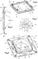
- FIG. 1 On the figure 1 , there is shown such a covering element 10. There is also shown one of the two electrical devices 60 that this covering element 10 is intended to cover.
- the terms “front” and “rear” will be used with respect to the direction of the user's gaze towards the wall on which this trim element 10 is attached.
- the front of an element will designate the side of this element that is facing towards the inside of the room and the back of this element will designate the side that faces the outside of the room.
- the present invention therefore relates more specifically to the covering element 10.
- the architecture of the electrical equipment 60 will then only be briefly described, at the end of this presentation. It will only be noted at this stage that such electrical equipment 60 comprises an equipment mechanism 80 and an equipment support 70.
- the trim element 10 mainly comprises a finishing plate 20 of elongated shape, which here delimits two access openings 22 provided to allow access to the functional parts of the two electrical equipment 60.
- the finishing plate 20 has more precisely here a front wall 21 flat and of rectangular shape, in which the access openings 22 are provided and which is bordered on the outside by a peripheral rim 24.
- this front wall 21 extends in a plane P1 defined by two axes X, Y, so that it extends orthogonally to a third axis Z (the axes X, Y, Z defining an orthonormal frame).
- the peripheral flange 24 extends rearward relative to the front wall 21, such that its edge can bear against the wall wall.
- the two access openings 22 are square in shape here. Alternatively, they could have different shapes.
- the trim element 10 further comprises means 50 for fixing the finishing plate 20 to the device supports 70 of the two electrical devices 60.
- a first part 50A of the fixing means 50 is more precisely intended to be fixed to a first device support 70, while a second part 50B of the fixing means 50 is intended to be fixed to the second device support 70.
- These fixing means 50 are designed to be able to be fixed simultaneously on the two device supports 70 of the electrical devices 60, whether the latter are placed in a multi-station electrical box with a very precise center distance or whether they are placed in electrical boxes separate single stations with a more random center distance and with a possible axial offset.
- the first part 50A of the fastening means 50 is secured with play to the finishing plate 20.
- the finishing plate 20 is equipped with two parts, hereinafter called “floating flanges 40", which are respectively attached to the edges of its two access openings 22, with play.
- Each floating collar 40 has a square shape in order to border the whole of the corresponding access opening. As a variant, it could have a different shape, for example a U-shape in which case it would border the access opening 22 only over part of its contour.
- each floating flange 40 comprises a frame 43 whose front edge is folded outwards to form a front peripheral rim 42 adapted to rest against the front face of the front wall 21 of the finishing plate 20.
- This front peripheral rim 42 thins outwards here, so as to present an aesthetic shape. It can, for the same reason, have a particular color and be made of a particular material, in order to be highlighted.
- the frame 43 of the floating flange 40 is designed to be interposed between the functional part of the electrical equipment 60 and the edge of the corresponding access opening 22 of the finishing plate 20.
- the floating collar 40 can border the functional part of the electrical equipment 60 even if the latter is not exactly well centered and oriented in the access opening 22 of the finishing plate.
- each floating flange 40 is mounted with play on the finishing plate 20 along the two axes X, Y This clearance is greater than a tenth of a millimeter. It is preferably greater than 5 tenths of a millimeter. It here equal to one millimeter, but it could be higher.
- each floating flange 40 is movable in translation on the finishing plate 20 along the X axis and along the Y axis, with a reduced clearance, and it is also movable in rotation around the Z axis, with a travel also reduced.
- each floating collar 40 with respect to the finishing plate 20 thus remains restricted, so as not to give the installer a feeling of poor assembly.
- the clearances offered by the two floating flanges 40 are added together, which makes it possible to compensate for greater faults in the center distance and misalignment of the two electrical devices 60 with respect to each other.
- the frame 43 also has, projecting from its rear edge, notches 44 provided to hook onto the rear of the front wall 21 of the finishing plate 20, as well as several latching lugs 51 (which form said part 50A or 50B of the fastening means 50).
- each floating flange 40 is designed to pinch the edge of the corresponding access opening 22 of the cover plate 20, i.e. to sandwich the front wall 21 of the finishing plate 20.
- a notch 44 is provided on each side of the frame 43, so as to ensure solid attachment of the floating collar 40 to the finishing plate 20.
- the notches 44 are provided so as not to impede the mobility of the floating collar 40 with respect to the finishing plate 20.
- each notch 44 extends from the rear edge of the frame 43 and is folded outwards so that the distance separating the front face of each notch 44 from the rear face of the front peripheral rim 42 is very slightly greater than the thickness of the finishing plate 20.
- each notch 44 is bevelled outwards, so as to form a ramp 45 which allows the mounting of the floating collar 40 on the finishing plate 20 by snap-fastening.
- each notch 44 is on the other hand flat and extends in a plane parallel to that of the rear face of the front peripheral rim 42, so as not to be able to be disengaged from the finishing plate 20 (except to exert a very high pull-out force, using a tool).
- each part 50A, 50B of the fastening means 50 here comprises several separate latching lugs 51.
- latching lugs 51 extend from the rear edge of the frame 43, in the extension of the latter (towards the rear), and they each carry on their outer faces at least one hooking tooth.
- each latching tab 51 carries a series of several hooking teeth, distributed at different heights relative to the frame 43 (from the front to the rear), so that the trim element 10 can s hang at different heights on the equipment supports 70 of the electrical equipment 60.
- each snap tab 51 is also split longitudinally in two identical parts, by a slot 52 whose function will appear clearly in the rest of this presentation.
- the snap lugs 51 and the notches 44 are shaped such that, when a force is exerted on the finishing plate 20 to snap the snap lugs 51 of the floating collars 40 onto the supports of fitting 70 of the electrical fittings 60, the notches 44 of the floating collars 40 do not come off the finishing plate 20.
- the notches 44 of the floating collars 40 are adapted to resist together a tearing force with respect to the finishing plate 20 which is greater than the effort required to snap the snap-fastening lugs 51 onto the device support 70 of the electrical device 60.
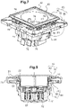
- This electrical equipment 60 conventionally comprises an equipment mechanism 80, an equipment support 70 and a trim 90.
- the fitting mechanism 80 could be of any type. It could thus be a switch mechanism, back and forth, electric dimmer, network socket (RJ45), telephone socket (RJ11), light, or even a detector (smoke , flood, temperature, movement or light). As depicted on the figure 1 , this is a power outlet mechanism.
- It comprises a rear base 81 which is globally parallelepipedic and which houses the motor of the apparatus (here the sockets 82 for receiving the pins of an electrical plug and the electrical terminals to be connected to the local electrical network).
- This rear plinth 81 is closed at the front by a functional part, called “trim 90” (which here delimits a well for receiving an electrical plug).
- This rear plinth 81 could be assembled to the device support 70, but in the embodiment represented here, it forms a single piece with the latter.
- the device support 70 is in the form of a square frame bordering the rear plinth 81 at the front.
- Two spaced apart ribs 75 are provided here, on each branch of the device support 70. In this way, whatever the orientation (vertical or horizontal) of the trim element 10 on the wall, the tabs snap 51 can cling to one or the other of these ribs 75.
- the installer begins by making an oblong opening or two circular openings in the wall, depending on whether he wishes to use a multi-station box or two single-station boxes.
- the installer then brings the electrical box(es) back into the wall, taking care to insert the electrical conduit through the bottom of the multi-station box or one of the single-station boxes.
- the installer then brings the two electrical devices into the multi-station box or into the single-station boxes, and screws them there.
- the installer attaches the covering element 10 to the front of the device supports 70 of the electrical devices 60, so that the snap-fastening lugs 51 of each of its floating collars 40 snap onto the ribs 75 of these device supports 70.
- each tab clip is attached to the cover plate via a connection made of slightly flexible material or via a guide, providing the desired clearance.
- finishing plate prefferably has more access openings, and for it to be provided to be attached to a greater number of electrical devices (typically 3 or 4).
- provision could be made for the floating collars 40 are secured to the finishing plate 20 with a clearance much greater than one millimeter.
- the front peripheral edge 42 and the notches 44 will have to be extended, so that they can still pinch the front wall 21 of the finishing plate 20. If the clearance is really large (several millimeters) and the notches are then very long, the snap-fastening of these notches 44 on the finishing plate 20 during the assembly of the covering element 10 can prove to be difficult.
Landscapes
- Engineering & Computer Science (AREA)
- Architecture (AREA)
- Civil Engineering (AREA)
- Structural Engineering (AREA)
- Casings For Electric Apparatus (AREA)
- Rectifiers (AREA)
- Compressor (AREA)
- Arc-Extinguishing Devices That Are Switches (AREA)
- Details Of Indoor Wiring (AREA)
- Switch Cases, Indication, And Locking (AREA)
Claims (13)
- Verkleidungselement (10) mit- einer Abdeckplatte (20), die mindestens zwei Öffnungen (22) für den Zugang zu den Funktionsteilen (90) zweier verschiedener, in zwei elektrischen Einzelboxen befestigter Elektrogeräte (60) begrenzt, und- Mitteln (44, 50) für die Befestigung der Abdeckplatte (20) an den beiden Elektrogeräten (60),wobei mindestens ein Teil (50A) der Befestigungsmittel (44, 50) an der Abdeckplatte (20) so mit Spiel befestigt ist, daß die Befestigungsmittel (44, 50) selbst dann spannungsfrei an den beiden Elektrogeräten (60) befestigt werden können, wenn die beiden Elektrogeräte (60) gegenüber den beiden Zugangsöffnungen leicht versetzt sind, wobei das Spiel größer als ein Zehntel Millimeter ist.
- Verkleidungselement (10) gemäß dem vorangehenden Anspruch, bei dem der Teil (50A) der Befestigungsmittel (44, 50) dazu ausgelegt ist, an einem der Elektrogeräte (60) befestigt zu werden, und bei dem ein anderer Teil (50B) der Befestigungsmittel (44, 50) dazu ausgelegt ist, an einem anderen der Elektrogeräte (60) befestigt zu werden.
- Verkleidungselement (10) gemäß dem vorangehenden Anspruch, bei dem jeder Teil (50A, 50B) der Befestigungsmittel (44, 50) mit Spiel an der Abdeckplatte (20) befestigt ist.
- Verkleidungselement (10) gemäß einem der vorangehenden Ansprüche, bei dem der Teil (50A) der Befestigungsmittel (44, 50) zu ein und demselben schwebenden Teil (40) gehört, das von der Abdeckplatte (20) verschieden ist und das mit Spiel an der Abdeckplatte (20) befestigt ist.
- Verkleidungselement (10) gemäß den beiden vorangehenden Ansprüchen, bei dem so viel schwebende Teile (40) vorgesehen sind, wie es Zugangsöffnungen (22) in der Abdeckplatte (20) gibt.
- Verkleidungselement (10) gemäß einem der beiden vorangehenden Ansprüche, bei dem das schwebende Teil (40) einen Kragen (43) aufweist, der eine der Zugangsöffnungen (22) innen umrandet und der den Teil (50A) der Befestigungsmittel (44, 50) trägt.
- Verkleidungselement (10) gemäß einem der drei vorangehenden Ansprüche, bei dem die Abdeckplatte (20) eine im Wesentlichen ebene Frontplatte (21) aufweist, durch die hindurch die Zugangsöffnungen (22) angeordnet sind, und bei der jedes schwebende Teil (40) mindestens einen vorderen Teil (42) und einen hinteren Teil (44) aufweist, die die Frontplatte (21) der Abdeckplatte (20) zwischen sich einschließen.
- Verkleidungselement (10) gemäß dem vorangehenden Anspruch, bei dem sich der vordere Teil (42) des Kragenteils (40) entlang des gesamten Umfangs einer der Zugangsöffnungen (22) der Abdeckplatte (20) erstreckt.
- Verkleidungselement (10) gemäß einem der beiden vorangehenden Ansprüche, bei dem jeder hintere Teil (44) des schwebenden Teils (40) mit dem Rest des schwebenden Teils (40) biegsam verbunden ist.
- Verkleidungselement (10) gemäß einem der vorangehenden Ansprüche, bei dem jeder Teil (50A) der Befestigungsmittel (50) mehrere einzelne Einrastzungen (51) aufweist.
- Verkleidungselement (10) gemäß den beiden vorangehenden Ansprüchen, bei dem die hinteren Teile (44) des schwebenden Teils (40) dazu ausgelegt sind, gemeinsam gegenüber der Abdeckplatte (20) einer Herausziehkraft zu widerstehen, die größer als die zum Einrasten der Einrastzungen (51) am Elektrogerät (60) notwendige Kraft ist.
- Verkleidungselement (10) gemäß einem der vorangehenden Ansprüche, bei dem der Teil (50A) der Befestigungsmittel (50) mit Spiel entlang zweier zueinander rechtwinkligen Achsen (X, Y) an der Abdeckplatte (20) befestigt ist.
- Elektrische Einheit mit mindestens zwei Elektrogeräten (60), dadurch gekennzeichnet, daß sie außerdem ein Verkleidungselement (10) gemäß einem der vorangehenden Ansprüche aufweist, dessen Teil (50A) der Befestigungsmittel (44, 50) an einem der beiden Elektrogeräte (60) befestigt ist.
Applications Claiming Priority (1)
| Application Number | Priority Date | Filing Date | Title |
|---|---|---|---|
| FR1756982A FR3069386B1 (fr) | 2017-07-21 | 2017-07-21 | Element d'habillage pour appareillage electrique |
Publications (2)
| Publication Number | Publication Date |
|---|---|
| EP3432432A1 EP3432432A1 (de) | 2019-01-23 |
| EP3432432B1 true EP3432432B1 (de) | 2022-08-17 |
Family
ID=60627728
Family Applications (1)
| Application Number | Title | Priority Date | Filing Date |
|---|---|---|---|
| EP18177944.8A Active EP3432432B1 (de) | 2017-07-21 | 2018-06-15 | Verkleidungselement für elektrogerät |
Country Status (6)
| Country | Link |
|---|---|
| EP (1) | EP3432432B1 (de) |
| ES (1) | ES2929243T3 (de) |
| FR (1) | FR3069386B1 (de) |
| HU (1) | HUE060299T2 (de) |
| MA (1) | MA45818B1 (de) |
| RU (1) | RU2769722C2 (de) |
Families Citing this family (1)
| Publication number | Priority date | Publication date | Assignee | Title |
|---|---|---|---|---|
| DE102021104869A1 (de) * | 2021-03-01 | 2022-09-01 | Schneider Electric Industries Sas | Blendrahmen für ein elektrisches installationsgerät |
Citations (2)
| Publication number | Priority date | Publication date | Assignee | Title |
|---|---|---|---|---|
| FR2844106A1 (fr) * | 2002-08-28 | 2004-03-05 | Legrand Sa | Appareil d'installation electrique domestique integrant une protection contre les projections de liquide |
| EP2802050A2 (de) * | 2013-03-15 | 2014-11-12 | Assa Abloy Ab | Universeller Halterungsring |
Family Cites Families (7)
| Publication number | Priority date | Publication date | Assignee | Title |
|---|---|---|---|---|
| FR2695532B1 (fr) * | 1992-09-04 | 1994-11-18 | Legrand Sa | Plaque de support pour appareillage électrique. |
| DE29803339U1 (de) * | 1998-02-25 | 1998-05-07 | Albrecht Jung GmbH & Co KG, 58579 Schalksmühle | Zwischenrahmen für ein elektrisches Installationsgerät |
| DE102004024093B4 (de) * | 2004-05-14 | 2013-11-14 | Berker Gmbh & Co. Kg | Abdeckung |
| ITRM20050161A1 (it) * | 2005-04-07 | 2006-10-08 | Bticino Spa | Placca di copertura e gruppo di parti, includente tale placca, per il montaggio a parete di un apparecchio elettrico. |
| FR2901451B1 (fr) * | 2006-05-22 | 2008-07-18 | Legrand France | Appareillage electrique etanche a disposer en saillie ou a encastrer dans une paroi |
| FR2986669B1 (fr) * | 2012-02-03 | 2014-10-31 | Legrand France | Support multi-appareillages de boitier electrique multipostes |
| FR2991821B1 (fr) * | 2012-06-08 | 2016-11-11 | Legrand France | Plaque de finition equipee de moyens de centrage sur un element interne d'un appareillage electrique |
-
2017
- 2017-07-21 FR FR1756982A patent/FR3069386B1/fr active Active
-
2018
- 2018-06-15 MA MA45818A patent/MA45818B1/fr unknown
- 2018-06-15 HU HUE18177944A patent/HUE060299T2/hu unknown
- 2018-06-15 EP EP18177944.8A patent/EP3432432B1/de active Active
- 2018-06-15 ES ES18177944T patent/ES2929243T3/es active Active
- 2018-07-20 RU RU2018126750A patent/RU2769722C2/ru active
Patent Citations (2)
| Publication number | Priority date | Publication date | Assignee | Title |
|---|---|---|---|---|
| FR2844106A1 (fr) * | 2002-08-28 | 2004-03-05 | Legrand Sa | Appareil d'installation electrique domestique integrant une protection contre les projections de liquide |
| EP2802050A2 (de) * | 2013-03-15 | 2014-11-12 | Assa Abloy Ab | Universeller Halterungsring |
Also Published As
| Publication number | Publication date |
|---|---|
| RU2018126750A3 (de) | 2021-10-08 |
| ES2929243T3 (es) | 2022-11-25 |
| EP3432432A1 (de) | 2019-01-23 |
| RU2769722C2 (ru) | 2022-04-05 |
| RU2018126750A (ru) | 2020-01-22 |
| HUE060299T2 (hu) | 2023-02-28 |
| FR3069386A1 (fr) | 2019-01-25 |
| FR3069386B1 (fr) | 2019-08-23 |
| MA45818A (fr) | 2019-01-23 |
| MA45818B1 (fr) | 2022-11-30 |
Similar Documents
| Publication | Publication Date | Title |
|---|---|---|
| EP2936634B1 (de) | Elektrisches ausrüstungsmodul | |
| EP2936637B1 (de) | Abnehmbares modul für eine elektrische ausrüstung, verdrahtungsdose zur aufnahme solch eines ausrüstungsmoduls und verfahren zum austauschen solch eines ausrüstungsmoduls | |
| EP3483997B1 (de) | Elektrisches gerät | |
| EP3138167A2 (de) | Elektrische vorrichtung mit gesicherter montage | |
| EP3432432B1 (de) | Verkleidungselement für elektrogerät | |
| EP2819257B1 (de) | Erweitertes Elektrogerät | |
| EP3840151B1 (de) | Schaltkasten und zugehörige elektrische ausrüstung | |
| EP3138168B1 (de) | Elektrische vorrichtung zum einsetzen in eine elektrodose mit einstellbarer ausrichtung | |
| EP3345269B1 (de) | Dose zum einbau in eine wand | |
| EP2075888A1 (de) | Halterung für elektrische Geräte mit mehreren Stationen zur horizontalen und vertikalen Montage, eine solche Halterung mit Querträger umfassende Baugruppe und ein elektrisches Gerät, das eine solche mit Gerätemechanismen ausgestattete Baugruppe umfasst | |
| EP3329561B1 (de) | Anordnung von elektrikteilen | |
| EP3840136B1 (de) | Mechanismus eines elektrischen geräts, entsprechende elektrische anordung und entsprechendes elektrisches gerät | |
| EP2515391B1 (de) | Mehrfachgeräteblock, der mit einem verschiebbaren Zubehörteil ausgestattet ist | |
| FR3043853A1 (fr) | Bague de reception d'une boite electrique a encastrer dans une paroi murale | |
| EP4042533A1 (de) | Träger für ein elektrisches gerät | |
| EP4078745A1 (de) | Zweiteiliges elektrisches gehäuse | |
| BE1013053A3 (fr) | Boite d'encastrement susceptible d'etre jumelee avec un autre, notamment pour appareillage electrique. | |
| FR3105623A1 (fr) | Embout passe-câble étanche, boîte électrique comprenant un tel embout passe-câble et appareillage électrique comportant un mécanisme d'appareillage rapporté dans une telle boîte électrique | |
| FR2951588A1 (fr) | Socle de connexion electrique montable sur rail | |
| FR2799058A1 (fr) | Adaptateur pour appareillage electrique presentant un sens de montage | |
| FR2669175A1 (fr) | Boitier ouvrant et modulable pour appareillage(s) electrique(s). | |
| FR3105616A1 (fr) | Appareillage électrique | |
| EP2068411A1 (de) | Elektrische Einbau-Ausrüstung mit Schnellanschluss | |
| FR2925256A1 (fr) | Appareillage electrique dont une partie est orientale pour etre adaptee a l'usage courant des utilisateurs | |
| FR3039333A1 (fr) | Appareillage et boite electriques a encastrer dans une paroi |
Legal Events
| Date | Code | Title | Description |
|---|---|---|---|
| PUAI | Public reference made under article 153(3) epc to a published international application that has entered the european phase |
Free format text: ORIGINAL CODE: 0009012 |
|
| STAA | Information on the status of an ep patent application or granted ep patent |
Free format text: STATUS: THE APPLICATION HAS BEEN PUBLISHED |
|
| AK | Designated contracting states |
Kind code of ref document: A1 Designated state(s): AL AT BE BG CH CY CZ DE DK EE ES FI FR GB GR HR HU IE IS IT LI LT LU LV MC MK MT NL NO PL PT RO RS SE SI SK SM TR |
|
| AX | Request for extension of the european patent |
Extension state: BA ME |
|
| STAA | Information on the status of an ep patent application or granted ep patent |
Free format text: STATUS: REQUEST FOR EXAMINATION WAS MADE |
|
| STAA | Information on the status of an ep patent application or granted ep patent |
Free format text: STATUS: EXAMINATION IS IN PROGRESS |
|
| 17P | Request for examination filed |
Effective date: 20190320 |
|
| RBV | Designated contracting states (corrected) |
Designated state(s): AL AT BE BG CH CY CZ DE DK EE ES FI FR GB GR HR HU IE IS IT LI LT LU LV MC MK MT NL NO PL PT RO RS SE SI SK SM TR |
|
| 17Q | First examination report despatched |
Effective date: 20190503 |
|
| GRAP | Despatch of communication of intention to grant a patent |
Free format text: ORIGINAL CODE: EPIDOSNIGR1 |
|
| STAA | Information on the status of an ep patent application or granted ep patent |
Free format text: STATUS: GRANT OF PATENT IS INTENDED |
|
| INTG | Intention to grant announced |
Effective date: 20220408 |
|
| GRAS | Grant fee paid |
Free format text: ORIGINAL CODE: EPIDOSNIGR3 |
|
| GRAA | (expected) grant |
Free format text: ORIGINAL CODE: 0009210 |
|
| STAA | Information on the status of an ep patent application or granted ep patent |
Free format text: STATUS: THE PATENT HAS BEEN GRANTED |
|
| AK | Designated contracting states |
Kind code of ref document: B1 Designated state(s): AL AT BE BG CH CY CZ DE DK EE ES FI FR GB GR HR HU IE IS IT LI LT LU LV MC MK MT NL NO PL PT RO RS SE SI SK SM TR |
|
| REG | Reference to a national code |
Ref country code: CH Ref legal event code: EP |
|
| REG | Reference to a national code |
Ref country code: DE Ref legal event code: R096 Ref document number: 602018039315 Country of ref document: DE |
|
| REG | Reference to a national code |
Ref country code: IE Ref legal event code: FG4D Free format text: LANGUAGE OF EP DOCUMENT: FRENCH |
|
| REG | Reference to a national code |
Ref country code: AT Ref legal event code: REF Ref document number: 1512790 Country of ref document: AT Kind code of ref document: T Effective date: 20220915 |
|
| REG | Reference to a national code |
Ref country code: ES Ref legal event code: FG2A Ref document number: 2929243 Country of ref document: ES Kind code of ref document: T3 Effective date: 20221125 |
|
| REG | Reference to a national code |
Ref country code: MA Ref legal event code: VAGR Ref document number: 45818 Country of ref document: MA Kind code of ref document: B1 |
|
| REG | Reference to a national code |
Ref country code: NL Ref legal event code: MP Effective date: 20220817 |
|
| REG | Reference to a national code |
Ref country code: LT Ref legal event code: MG9D |
|
| PG25 | Lapsed in a contracting state [announced via postgrant information from national office to epo] |
Ref country code: SE Free format text: LAPSE BECAUSE OF FAILURE TO SUBMIT A TRANSLATION OF THE DESCRIPTION OR TO PAY THE FEE WITHIN THE PRESCRIBED TIME-LIMIT Effective date: 20220817 Ref country code: RS Free format text: LAPSE BECAUSE OF FAILURE TO SUBMIT A TRANSLATION OF THE DESCRIPTION OR TO PAY THE FEE WITHIN THE PRESCRIBED TIME-LIMIT Effective date: 20220817 Ref country code: PT Free format text: LAPSE BECAUSE OF FAILURE TO SUBMIT A TRANSLATION OF THE DESCRIPTION OR TO PAY THE FEE WITHIN THE PRESCRIBED TIME-LIMIT Effective date: 20221219 Ref country code: NO Free format text: LAPSE BECAUSE OF FAILURE TO SUBMIT A TRANSLATION OF THE DESCRIPTION OR TO PAY THE FEE WITHIN THE PRESCRIBED TIME-LIMIT Effective date: 20221117 Ref country code: NL Free format text: LAPSE BECAUSE OF FAILURE TO SUBMIT A TRANSLATION OF THE DESCRIPTION OR TO PAY THE FEE WITHIN THE PRESCRIBED TIME-LIMIT Effective date: 20220817 Ref country code: LV Free format text: LAPSE BECAUSE OF FAILURE TO SUBMIT A TRANSLATION OF THE DESCRIPTION OR TO PAY THE FEE WITHIN THE PRESCRIBED TIME-LIMIT Effective date: 20220817 Ref country code: LT Free format text: LAPSE BECAUSE OF FAILURE TO SUBMIT A TRANSLATION OF THE DESCRIPTION OR TO PAY THE FEE WITHIN THE PRESCRIBED TIME-LIMIT Effective date: 20220817 Ref country code: FI Free format text: LAPSE BECAUSE OF FAILURE TO SUBMIT A TRANSLATION OF THE DESCRIPTION OR TO PAY THE FEE WITHIN THE PRESCRIBED TIME-LIMIT Effective date: 20220817 |
|
| REG | Reference to a national code |
Ref country code: AT Ref legal event code: MK05 Ref document number: 1512790 Country of ref document: AT Kind code of ref document: T Effective date: 20220817 |
|
| PG25 | Lapsed in a contracting state [announced via postgrant information from national office to epo] |
Ref country code: PL Free format text: LAPSE BECAUSE OF FAILURE TO SUBMIT A TRANSLATION OF THE DESCRIPTION OR TO PAY THE FEE WITHIN THE PRESCRIBED TIME-LIMIT Effective date: 20220817 Ref country code: IS Free format text: LAPSE BECAUSE OF FAILURE TO SUBMIT A TRANSLATION OF THE DESCRIPTION OR TO PAY THE FEE WITHIN THE PRESCRIBED TIME-LIMIT Effective date: 20221217 Ref country code: HR Free format text: LAPSE BECAUSE OF FAILURE TO SUBMIT A TRANSLATION OF THE DESCRIPTION OR TO PAY THE FEE WITHIN THE PRESCRIBED TIME-LIMIT Effective date: 20220817 Ref country code: GR Free format text: LAPSE BECAUSE OF FAILURE TO SUBMIT A TRANSLATION OF THE DESCRIPTION OR TO PAY THE FEE WITHIN THE PRESCRIBED TIME-LIMIT Effective date: 20221118 |
|
| REG | Reference to a national code |
Ref country code: HU Ref legal event code: AG4A Ref document number: E060299 Country of ref document: HU |
|
| PG25 | Lapsed in a contracting state [announced via postgrant information from national office to epo] |
Ref country code: SM Free format text: LAPSE BECAUSE OF FAILURE TO SUBMIT A TRANSLATION OF THE DESCRIPTION OR TO PAY THE FEE WITHIN THE PRESCRIBED TIME-LIMIT Effective date: 20220817 Ref country code: RO Free format text: LAPSE BECAUSE OF FAILURE TO SUBMIT A TRANSLATION OF THE DESCRIPTION OR TO PAY THE FEE WITHIN THE PRESCRIBED TIME-LIMIT Effective date: 20220817 Ref country code: DK Free format text: LAPSE BECAUSE OF FAILURE TO SUBMIT A TRANSLATION OF THE DESCRIPTION OR TO PAY THE FEE WITHIN THE PRESCRIBED TIME-LIMIT Effective date: 20220817 Ref country code: CZ Free format text: LAPSE BECAUSE OF FAILURE TO SUBMIT A TRANSLATION OF THE DESCRIPTION OR TO PAY THE FEE WITHIN THE PRESCRIBED TIME-LIMIT Effective date: 20220817 Ref country code: AT Free format text: LAPSE BECAUSE OF FAILURE TO SUBMIT A TRANSLATION OF THE DESCRIPTION OR TO PAY THE FEE WITHIN THE PRESCRIBED TIME-LIMIT Effective date: 20220817 |
|
| REG | Reference to a national code |
Ref country code: DE Ref legal event code: R097 Ref document number: 602018039315 Country of ref document: DE |
|
| PG25 | Lapsed in a contracting state [announced via postgrant information from national office to epo] |
Ref country code: SK Free format text: LAPSE BECAUSE OF FAILURE TO SUBMIT A TRANSLATION OF THE DESCRIPTION OR TO PAY THE FEE WITHIN THE PRESCRIBED TIME-LIMIT Effective date: 20220817 Ref country code: EE Free format text: LAPSE BECAUSE OF FAILURE TO SUBMIT A TRANSLATION OF THE DESCRIPTION OR TO PAY THE FEE WITHIN THE PRESCRIBED TIME-LIMIT Effective date: 20220817 |
|
| PLBE | No opposition filed within time limit |
Free format text: ORIGINAL CODE: 0009261 |
|
| STAA | Information on the status of an ep patent application or granted ep patent |
Free format text: STATUS: NO OPPOSITION FILED WITHIN TIME LIMIT |
|
| PG25 | Lapsed in a contracting state [announced via postgrant information from national office to epo] |
Ref country code: AL Free format text: LAPSE BECAUSE OF FAILURE TO SUBMIT A TRANSLATION OF THE DESCRIPTION OR TO PAY THE FEE WITHIN THE PRESCRIBED TIME-LIMIT Effective date: 20220817 |
|
| 26N | No opposition filed |
Effective date: 20230519 |
|
| PG25 | Lapsed in a contracting state [announced via postgrant information from national office to epo] |
Ref country code: SI Free format text: LAPSE BECAUSE OF FAILURE TO SUBMIT A TRANSLATION OF THE DESCRIPTION OR TO PAY THE FEE WITHIN THE PRESCRIBED TIME-LIMIT Effective date: 20220817 |
|
| PG25 | Lapsed in a contracting state [announced via postgrant information from national office to epo] |
Ref country code: MC Free format text: LAPSE BECAUSE OF FAILURE TO SUBMIT A TRANSLATION OF THE DESCRIPTION OR TO PAY THE FEE WITHIN THE PRESCRIBED TIME-LIMIT Effective date: 20220817 |
|
| PG25 | Lapsed in a contracting state [announced via postgrant information from national office to epo] |
Ref country code: MC Free format text: LAPSE BECAUSE OF FAILURE TO SUBMIT A TRANSLATION OF THE DESCRIPTION OR TO PAY THE FEE WITHIN THE PRESCRIBED TIME-LIMIT Effective date: 20220817 |
|
| REG | Reference to a national code |
Ref country code: CH Ref legal event code: PL |
|
| REG | Reference to a national code |
Ref country code: BE Ref legal event code: MM Effective date: 20230630 |
|
| GBPC | Gb: european patent ceased through non-payment of renewal fee |
Effective date: 20230615 |
|
| PG25 | Lapsed in a contracting state [announced via postgrant information from national office to epo] |
Ref country code: LU Free format text: LAPSE BECAUSE OF NON-PAYMENT OF DUE FEES Effective date: 20230615 |
|
| REG | Reference to a national code |
Ref country code: IE Ref legal event code: MM4A |
|
| PG25 | Lapsed in a contracting state [announced via postgrant information from national office to epo] |
Ref country code: LU Free format text: LAPSE BECAUSE OF NON-PAYMENT OF DUE FEES Effective date: 20230615 |
|
| PG25 | Lapsed in a contracting state [announced via postgrant information from national office to epo] |
Ref country code: IE Free format text: LAPSE BECAUSE OF NON-PAYMENT OF DUE FEES Effective date: 20230615 |
|
| PG25 | Lapsed in a contracting state [announced via postgrant information from national office to epo] |
Ref country code: IE Free format text: LAPSE BECAUSE OF NON-PAYMENT OF DUE FEES Effective date: 20230615 Ref country code: CH Free format text: LAPSE BECAUSE OF NON-PAYMENT OF DUE FEES Effective date: 20230630 Ref country code: GB Free format text: LAPSE BECAUSE OF NON-PAYMENT OF DUE FEES Effective date: 20230615 |
|
| PG25 | Lapsed in a contracting state [announced via postgrant information from national office to epo] |
Ref country code: IT Free format text: LAPSE BECAUSE OF FAILURE TO SUBMIT A TRANSLATION OF THE DESCRIPTION OR TO PAY THE FEE WITHIN THE PRESCRIBED TIME-LIMIT Effective date: 20220817 Ref country code: BE Free format text: LAPSE BECAUSE OF NON-PAYMENT OF DUE FEES Effective date: 20230630 |
|
| PG25 | Lapsed in a contracting state [announced via postgrant information from national office to epo] |
Ref country code: BG Free format text: LAPSE BECAUSE OF FAILURE TO SUBMIT A TRANSLATION OF THE DESCRIPTION OR TO PAY THE FEE WITHIN THE PRESCRIBED TIME-LIMIT Effective date: 20220817 |
|
| PG25 | Lapsed in a contracting state [announced via postgrant information from national office to epo] |
Ref country code: BG Free format text: LAPSE BECAUSE OF FAILURE TO SUBMIT A TRANSLATION OF THE DESCRIPTION OR TO PAY THE FEE WITHIN THE PRESCRIBED TIME-LIMIT Effective date: 20220817 |
|
| PGFP | Annual fee paid to national office [announced via postgrant information from national office to epo] |
Ref country code: DE Payment date: 20250520 Year of fee payment: 8 |
|
| PGFP | Annual fee paid to national office [announced via postgrant information from national office to epo] |
Ref country code: HU Payment date: 20250613 Year of fee payment: 8 Ref country code: FR Payment date: 20250520 Year of fee payment: 8 |
|
| PG25 | Lapsed in a contracting state [announced via postgrant information from national office to epo] |
Ref country code: CY Free format text: LAPSE BECAUSE OF FAILURE TO SUBMIT A TRANSLATION OF THE DESCRIPTION OR TO PAY THE FEE WITHIN THE PRESCRIBED TIME-LIMIT; INVALID AB INITIO Effective date: 20180615 |
|
| PGFP | Annual fee paid to national office [announced via postgrant information from national office to epo] |
Ref country code: ES Payment date: 20250701 Year of fee payment: 8 |
|
| VSFP | Annual fee paid to validation state [announced via postgrant information from national office to epo] |
Ref country code: MA Payment date: 20221027 Year of fee payment: 6 |
|
| VSFP | Annual fee paid to validation state [announced via postgrant information from national office to epo] |
Ref country code: MA Payment date: 20240530 Year of fee payment: 7 |
|
| VSFP | Annual fee paid to validation state [announced via postgrant information from national office to epo] |
Ref country code: MA Payment date: 20250612 Year of fee payment: 8 |
|
| PG25 | Lapsed in a contracting state [announced via postgrant information from national office to epo] |
Ref country code: TR Free format text: LAPSE BECAUSE OF FAILURE TO SUBMIT A TRANSLATION OF THE DESCRIPTION OR TO PAY THE FEE WITHIN THE PRESCRIBED TIME-LIMIT Effective date: 20220817 |