EP3432696B1 - Wärmeübertragungsanordnung für eine wärmeabgebende vorrichtung - Google Patents
Wärmeübertragungsanordnung für eine wärmeabgebende vorrichtung Download PDFInfo
- Publication number
- EP3432696B1 EP3432696B1 EP18176970.4A EP18176970A EP3432696B1 EP 3432696 B1 EP3432696 B1 EP 3432696B1 EP 18176970 A EP18176970 A EP 18176970A EP 3432696 B1 EP3432696 B1 EP 3432696B1
- Authority
- EP
- European Patent Office
- Prior art keywords
- heat
- module
- heat transfer
- transfer assembly
- coolant
- Prior art date
- Legal status (The legal status is an assumption and is not a legal conclusion. Google has not performed a legal analysis and makes no representation as to the accuracy of the status listed.)
- Active
Links
Images




Classifications
-
- H—ELECTRICITY
- H05—ELECTRIC TECHNIQUES NOT OTHERWISE PROVIDED FOR
- H05K—PRINTED CIRCUITS; CASINGS OR CONSTRUCTIONAL DETAILS OF ELECTRIC APPARATUS; MANUFACTURE OF ASSEMBLAGES OF ELECTRICAL COMPONENTS
- H05K7/00—Constructional details common to different types of electric apparatus
- H05K7/20—Modifications to facilitate cooling, ventilating, or heating
- H05K7/2089—Modifications to facilitate cooling, ventilating, or heating for power electronics, e.g. for inverters for controlling motor
- H05K7/20927—Liquid coolant without phase change
-
- H—ELECTRICITY
- H10—SEMICONDUCTOR DEVICES; ELECTRIC SOLID-STATE DEVICES NOT OTHERWISE PROVIDED FOR
- H10W—GENERIC PACKAGES, INTERCONNECTIONS, CONNECTORS OR OTHER CONSTRUCTIONAL DETAILS OF DEVICES COVERED BY CLASS H10
- H10W40/00—Arrangements for thermal protection or thermal control
- H10W40/20—Arrangements for cooling
- H10W40/22—Arrangements for cooling characterised by their shape, e.g. having conical or cylindrical projections
-
- G—PHYSICS
- G06—COMPUTING OR CALCULATING; COUNTING
- G06F—ELECTRIC DIGITAL DATA PROCESSING
- G06F1/00—Details not covered by groups G06F3/00 - G06F13/00 and G06F21/00
- G06F1/16—Constructional details or arrangements
- G06F1/20—Cooling means
-
- H—ELECTRICITY
- H10—SEMICONDUCTOR DEVICES; ELECTRIC SOLID-STATE DEVICES NOT OTHERWISE PROVIDED FOR
- H10W—GENERIC PACKAGES, INTERCONNECTIONS, CONNECTORS OR OTHER CONSTRUCTIONAL DETAILS OF DEVICES COVERED BY CLASS H10
- H10W40/00—Arrangements for thermal protection or thermal control
- H10W40/40—Arrangements for thermal protection or thermal control involving heat exchange by flowing fluids
- H10W40/47—Arrangements for thermal protection or thermal control involving heat exchange by flowing fluids by flowing liquids, e.g. forced water cooling
-
- G—PHYSICS
- G06—COMPUTING OR CALCULATING; COUNTING
- G06F—ELECTRIC DIGITAL DATA PROCESSING
- G06F2200/00—Indexing scheme relating to G06F1/04 - G06F1/32
- G06F2200/20—Indexing scheme relating to G06F1/20
- G06F2200/201—Cooling arrangements using cooling fluid
Definitions
- Embodiments of the present disclosure relate to a heat transfer assembly required for cooling a heat emitting device, such as a power electronic devices or for cooling multiple heat emitting devices.
- the devices are mounted on a cooling plate, referred generally as a cold-plate which is subjected to an internal, single-phase fluid flow of a liquid coolant.
- Heat generated by the electronic device is conducted through three layers that include, an electronic device baseplate, a Thermal Interface Material (TIM), and the cold-plate body. Finally, the heat is convected into the liquid coolant and transported downstream, to be rejected to ambient.
- a cooling plate referred generally as a cold-plate which is subjected to an internal, single-phase fluid flow of a liquid coolant.
- Heat generated by the electronic device is conducted through three layers that include, an electronic device baseplate, a Thermal Interface Material (TIM), and the cold-plate body. Finally, the heat is convected into the liquid coolant and transported downstream, to be rejected to ambient.
- TIM Thermal Interface Material
- Some improvements to this cooling also include direct cooling solutions where the TIM layer and the cold-plate body conduction layers are removed and the coolant flow is applied to the baseplate of the power electronic device.
- the direct cooling designs often suffer from leak related issues that cause damage to the power electronic device and is a serious reliability concern in the manufacturing of these cooling solutions. Further, some of these designs also suffer from coolant flow distribution issues. Usually, a single pump is used to drive the coolant through multiple flow paths. In several designs, the flow is imbalanced, when one path has a different resistance to coolant flow than the others. Another concern is a water hammer effect in some designs which arises when a high velocity flow bypasses some paths, and creates a much higher flowrate through the final path.
- US 6 404 628 B1 discloses a heat transfer assembly coupled to a heat emitting device for dissipating heat from the heat emitting device, including a module comprising a body having a first, top part and a second part, the first part having a top surface for mounting heat emitting devices, such as a plurality of IGBT modules mounted to a pin-fin heat sink, thereto and a U-shaped coolant cavity formed adjacent the top of the body, and the second part having a solid portion.
- a seal component is disposed at the top surface of the first part of the body between the heat emitting devices and the at least one module.
- the first part and the second part are mechanically connected to each other by being integrally formed as a single unit.
- a module coolant inlet and a module coolant outlet are fluidly connected to the U-shaped coolant cavity to cause a coolant to flow into the inlet, through the U-shaped coolant cavity and out of the outlet absorbing heat from the heat emitting devices.
- Portions of the heat emitting devices like the pin-fin heat sink, may be directly mounted to the first, top part of the module using bolts.
- US 2015/0195951 A1 discloses a cooled electronic assembly having a substrate having a first coefficient of thermal expansion, at least one heat source, in the form of an electronic device or power electronics, operably coupled to the substrate, a carrier plate of a thermally conductive material, operably coupled to the substrate, and a liquid-cooled heat sink.
- the heat sink, carrier plate, and substrate are configured to direct heat away from the at least one heat source.
- a heat transfer assembly coupled to a heat emitting device for dissipating heat from the heat emitting device.
- the heat transfer assembly includes a module inlet for receiving a coolant; at least one module comprising a first part having a recess to receive a portion of the heat emitting device, and a second part having a shaped cutout portion and a solid portion, wherein the second part allows a uniform compression of a seal component disposed on the first part between the heat emitting device and the at least one module, and wherein the first part and the second part are mechanically connected to each other; and a module outlet for discharging a heat absorbed coolant after absorbing heat from the heat emitting device, where the at least one module is connected to the module inlet and the module outlet.
- a portion of the heat emitting device is bolted to the at least one module using bolts, where each bolt passes through the first part and the second part.
- the at least one module is flexible to achieve a convex curvature or a concave curvature for load balance to ensure uniform compression for leak-proof sealing.
- the heat transfer assembly includes multiple modules arranged in a symmetrical layout to allow a symmetrical flow of the coolant in the heat transfer assembly.
- the different aspects of a heat transfer assembly described herein relate to reliable cooling arrangement for any heat emitting devices that produce heat during their operation.
- One such device is a power converter device that uses semiconductor based circuitry.
- Power Converters typically comprise semiconductor switches optionally in combination with other circuitry such as diodes, capacitors, and/or inductors.
- the heat transfer assembly described herein is particularly beneficial for power converters including silicon carbide switches due to the high heat fluxes associated with such switches.
- the different aspects described herein focus on geometry of the heat transfer assembly that enables uniform compression of a sealing component that is used to seal the heat emitting device with the heat transfer device and consequently solves any leak related issues that otherwise occur as explained herein above.
- the different embodiments also address other aspects related to heat transfer assembly, such as providing a symmetrical flow path for the coolant, that further enhances the reliable operation of the heat transfer assembly.
- These embodiments provide simplicity for facile manufacturing without introducing new components, and the materials used for fabrication of the heat transfer assembly provide an electrically insulating structure where the electromagnetic interferences (EMI) in the heat emitting device are also reduced, thereby improving the operation of the heat emitting device as well.
- EMI electromagnetic interferences
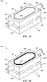
- FIG. 1A is a non-limiting implementation of an embodiment of a heat transfer assembly 100 for transferring heat from an heat emitting device (not shown in FIG.1A , however is shown in FIG 8).
- the heat transfer assembly 100 includes at least one module shown as 110, that has a first part 120 having a recess 130 to receive a portion of the heat emitting device, and a seal component disposed in the recess (shown in FIG. IB), and a second part 140 having a shaped cutout portion 150 and a solid portion 160.
- the second part 140 allows a uniform compression of the sealing component, thus provides a leak-proof sealing for the seal component disposed between the heat emitting device and the module and thus prevents an occurance of leak that can damage the heat emitting device.
- the module 110 is flexible (to the order of 1 mm) to achieve a convex curvature or a concave curvature for load balance to ensure uniform compression for the leak-proof sealing.
- the seal component referred herein in one example is an o-ring seal, and a gasket in another example, and is shown in FIG. 1B by reference numeral 132.
- the sealing component (o-ring, gasket, etc.) could be a separate component, or it could even be integrated into the module through additive manufacturing methods.
- Other components in FIG. 1B are same as shown and described in reference to FIG. 1A . Further details related to compression of the sealing component are described in more detail in reference to FIG. 2A-2F .
- the first part 110 and the second part 130 are mechanically connected to each other.
- the first part 120 and the second part 140 are fabricated as a single integrated unit.
- the heat transfer assembly 100 shown in FIG.1A further includes a module inlet 170 for receiving a coolant and a module outlet 180 for discharging the heat absorbed coolant.
- the coolant is typically a liquid coolant such as water, de-ionised water, water-glycol, and fluoroketones like Novec 649TM for the phase change applications.
- the module inlet 170 and module outlet 180 are coupled to the portion of recess 130 underlying the heat emitting device such that that the coolant touches the portion of the heat emitting device (also sometimes referred to as a baseplate) directly and therefore achieves efficient and effective cooling for the heat emitting device.
- the coolant in one example is a single phase coolant, which implies that the liquid coolant remains liquid even after absorbing heat from the heat transfer device.
- the coolant is a phase change coolant, which implies that the liquid coolant changes into vapor after absorbing heat from the heat transfer device.
- the heat transfer assembly also includes holes for example 190, 190', 190", 190"' that are seen in the drawing, for receiving respective bolts (not shown) for securing the heat emitting device mechanically with the heat transfer assembly 110. It would be understood by those skilled in the art that the desired portion of the heat emitting device is bolted to the respective module using these bolts, where each bolt passes through the first part 120 and the second part 140.
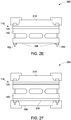
- FIG. 2A-2F further show free body diagrams to explain the non-uniform compression of the sealing component in some prior art designs, as well as the free body diagrams related to embodiments of this disclosure that provide uniform compression of the sealing components.
- a leak occurs at the center 210 of the module 220 (the point farthest from the bolts) due to a long distance which spans the clamping bolts, the clamping force of bolts is shown by the arrows 230 and 240, and the offset force is shown by 250 and 260.
- the center 210 becomes weak over time and that leads to a leak through the sealing component.
- FIG. 2B shows the modified free body diagram 270 for the different embodiments described herein where the reaction forces 230 and 240 applied by bolts and nuts are offset by introducing a four-point bending shown by offset forces 280 and 290, which provides uniform O-ring compression.
- the module 110 of the heat transfer assembly described in different embodiments is therefore able to flex due to the four-point bending and accommodate a concave curvature, as shown diagram 300 in FIG. 2C or a convex curvature, as shown in diagram 350 in FIG. 2D .
- the free body diagram 360 in FIG. 2E shows one embodiment where a single module that implements the features of FIG. 2B - FIG. 2D .
- FIGs 2C-2D also show is the portion of the heat emitting device indicated by reference numeral 310.
- FIG. 2E shows nuts 194 and bolts 192 that are used to attach the module 110 with a portion of the heat emitting device shown by reference numeral 310.
- FIG. 2F shows another embodiment 380 where a double-sided component implements the features of FIG. 2B - FIG. 2D .
- the module includes a third part 320 in addition to the first part 120 and the second part 140, described in reference to FIG. 1 .
- the second part 140 is disposed between the first part 120 and the third part 320, and the third part 320 is a mirror of the first part.
- the heat emitting devices 310 and 390 such as power converters can be positioned on both sides as the first part and the third part, both become accessible for receiving the power converters and the second part provides the required cooling to both the power converters that are positioned on top of the first part and the third part.
- the bolts will pass through the first part, the second part, and the third part and the power converter, or any other heat emitting device.
- first part and second part or first part, second part and third part can be all in one integrated unit as mentioned earlier or in some other embodiments, for example an embodiment 400 as shown in FIG. 3 , these parts, for example the first part and the second part may use a snap fit, using grooves for example to connect to each other, as indicated by reference numeral 410.
- the other components in FIG. 3 are same as in FIG. 1
- FIG. 4 a diagrammatic representation 500 of another embodiment is disclosed where the heat transfer assembly has multiple modules 510, 520, 530 arranged in a linear array, each module having a respective module inlet shown by reference numeral 540, 550, 560 and respective outlet shown by reference numeral 570, 580, and 590 and all the modules connected to a tubing with an assembly inlet 600 and an assembly outlet 610 for providing flow path for the coolant.
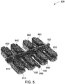
- FIG. 5 is a diagrammatic representation 800 of another embodiment with eight individual modules in one integrated unit, where modules 810, 830 are a mirror of modules 820 and 840 respectively, and modules 850 and 870 are mirror of modules 860 and 880 respectively. Also, the modules 810, 830, 850, 870 are all on one side, whereas the mirror modules 820, 840, 860, and 880 are on the other side separated by a separator 920 A distributed tubing 910 allows the assembly inlet 890 and the assembly outlet 900 to be connected to individual module inlet and module outlet as shown.
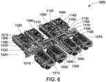
- FIG. 6 is another diagrammatic representation 1000 where the multiple modules 1010, 1030, 1050, 1070 and mirror modules 1020, 1040, 1060, 1080 are arranged such that there is a symmetrical layout to allow a symmetrical flow direction for the coolant in the heat transfer assembly 1000 from the inlet 1090 through the flow channels to enter the respective module inlets of each of the modules, and similarly provides a symmetrical flow path for exit of the coolant through each of the module outlet into the outlet 1300 of the heat transfer assembly 1000.
- a distributed tubing 1310 provides connection of the assembly inlet with each of the module inlet and of each of module outlet with the assembly outlet of the heat transfer assembly.
- the symmetrical flow of the coolant ensures that there is no build up of coolant in any one of the modules with respect to others, and retains a balanced flowpath throughout the heat transfer assembly. As shown, the flow splits in half three times, effectively disrupting the water hammer which is known to cause flow imbalances in prior art designs.
- the symmetrical layout makes the flow path from the inlet to each individual module similar. This makes the flow resistance in each individual module similar, and achieves balanced flow distribution as mentioned herein above.
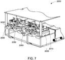
- FIG. 7 a diagrammatic representation 2000 shows a power converter drive with different power converters 2010, 2030, 2050 positioned on top of the respective modules 2020, 2040, and 2060 of the the respective heat transfer assemblies explained in reference to above embodiments, for example embodiments of FIG. 5 and FIG. 6 .
- the individual module or the multiple modules described herein are made from at least one of a polymer material, copolymer material or a composite material, such as polymer-ceramic composite, carbon fibre composite, other non-metals, metals and alloys.
- a polymer material such as polymer-ceramic composite, carbon fibre composite, other non-metals, metals and alloys.
- the entire heat transfer assembly is made from a same material. Further other materials that are compatible with faster manufacturing techniques such as three dimensional printing will also be suitable for the multiple modules described herein.
- the different embodiments of the modules of the heat transfer assembly described herein achieve effective cooling through direct contact of the coolant with the heat emitting device and in addition the modules ensure a leak proof sealing to overcome non-uniform compression of the sealing component, that is critical for heat emitting devices such as power converters and an enabler for direct liquid cooling of heat emitting devices.
- This sealing concept is an enabler for direct liquid cooling, which will reduce the thermal resistance from the power converter device (for example a semiconductor chip) to air by ⁇ 20degC/kW (degree Centigrade/kilo Watt).
- the power converter device will have a greater power rating for the same junction temperature, or alternately a more efficient power conversion (lower junction temperature) for the same power rating.
- a high thermal conductivity material is no longer required in the heat transfer assembly described herein, it can be manufactured from an economical polymer or composite material. Such materials are good insulators, and therefore serve the function of thermal insulation along with providing structural support.
- the insulating structure will also reduce EMI, since the large antenna-like active heatsinks are not required that cause EMI in prior art designs.
- several components in the prior art cooling arrangements such as heatsink, TIM, and accompanying isolating components are made redundant through the different embodiments described herein, enabling a simpler, more compact cooling design with lower labor cost for assembly.
- the embodiments of the heat transfer assembly described herein also achieve a symmetric flow path for the coolant to avoid any pressure build-up due to non-uniform flow build-up in the flow path for the coolant.
- the modular structure of the heat transfer assembly described herein makes it compatible for additive manufacturing.
- the heat transfer assembly is additively manufactured and is injection molded in another implementation, which allow complex, three dimensional geometries for internal flow paths (relative to prior art machined aluminum designs).
- heat transfer assembly has been described herein in relation to cooling of power converter devices as heat emitting devices, however, there the heat emitting devices could be any semiconductor based devices or circuits, these may be a part of computer processing equipment, or electrical motors and generators, or any devices that generate heat during their operation and require cooling for safe operation of their components.
Landscapes
- Engineering & Computer Science (AREA)
- Microelectronics & Electronic Packaging (AREA)
- Physics & Mathematics (AREA)
- Theoretical Computer Science (AREA)
- Thermal Sciences (AREA)
- Human Computer Interaction (AREA)
- General Engineering & Computer Science (AREA)
- General Physics & Mathematics (AREA)
- Cooling Or The Like Of Electrical Apparatus (AREA)
- Cooling Or The Like Of Semiconductors Or Solid State Devices (AREA)
Claims (12)
- Wärmeübertragungsanordnung (100), die mit einer Wärme abstrahlenden Vorrichtung (310, 390) gekoppelt ist, um Wärme von der Wärme abstrahlenden Vorrichtung (310, 390) abzuleiten, wobei die Wärmeübertragungsanordnung (100) aufweist:einen Moduleinlass (170, 540, 550, 560) zum Aufnehmen eines Kühlmittels;wenigstens ein Modul (110), das einen ersten Teil (120) mit einer Aussparung (130), um einen Abschnitt der Wärme abstrahlenden Vorrichtung (310, 390) aufzunehmen, und einen zweiten Teil (140) aufweist, der einen geformten ausgeschnittenen Abschnitt (150) und einen massiven Abschnitt (160) aufweist;eine Dichtungskomponente (132), die zwischen der Wärme abstrahlenden Vorrichtung (310, 390) und dem wenigstens einen Modul (110) angeordnet ist;einen Modulauslass (180) zum Ausgeben eines Wärme absorbierten Kühlmittels nach der Aufnahme von Wärme aus der Wärme abstrahlenden Vorrichtung (310, 390), wobei das wenigstens eine Modul (110) mit dem Moduleinlass (170, 540, 550, 560) und dem Modulauslass (180) verbunden ist,wobei der zweite Teil (140) eine gleichmäßige Kompression der Dichtungskomponente (132) ermöglicht und wobei der erste Teil (120) und der zweite Teil (140) mechanisch miteinander verbunden sind,wobei ein Abschnitt der Wärme abstrahlenden Vorrichtung (310, 390) mit dem wenigstens einen Modul (110) unter Verwendung von Schraubenbolzen (190, 190', 190'', 190''') verschraubt ist, wobei jeder Schraubenbolzen (190, 190', 190'', 190''') durch den ersten Teil (120) und den zweiten Teil (140) hindurchführt, undwobei das wenigstens eine Modul (110) flexibel ist, um eine konvexe Krümmung oder eine konkave Krümmung für den Lastausgleich zu erreichen, um eine gleichmäßige Kompression für eine leckagedichte Abdichtung sicherzustellen.
- Wärmeübertragungsanordnung (100) nach Anspruch 1, wobei das Kühlmittel wenigstens eines von einem Einphasenkühlmittel oder einem Phasenänderungskühlmittel ist.
- Wärmeübertragungsanordnung (100) nach Anspruch 1 oder 2, wobei der geformte ausgeschnittene Abschnitt (150) und der massive Abschnitt (160) in dem zweiten Teil (140) ein Vierpunkt-Biegen für eine gleichmäßige Kompression der Dichtungskomponente (132) ermöglichen.
- Wärmeübertragungsanordnung (100) nach einem beliebigen vorhergehenden Anspruch, die mehrere Module (1010, 1030, 1050, 1070, 1020, 1040, 1060, 1080) aufweist, die in einer symmetrischen Anordnung angeordnet sind, um eine symmetrische Strömung des Kühlmittels in der Wärmeübertragungsanordnung (100) zu ermöglichen.
- Wärmeübertragungsanordnung (100) nach Anspruch 4, die ferner aufweist: einen Anordnungseinlass (600, 890) zur Aufnahme des Kühlmittels, wobei die symmetrische Anordnung eine Strömungsrichtung für das Kühlmittel zum Eintritt in jedes der mehreren Module bereitstellt; und einen Anordnungsauslass (610, 900) zur Ausgabe des von den mehreren Modulen (1010, 1030, 1050, 1070, 1020, 1040, 1060, 1080) empfangenen Wärme absorbierten Kühlmittels, wobei der Anordnungseinlass (600, 890) und der Anordnungsauslass (610, 900) mit dem Moduleinlass (170, 540, 550, 560) und dem Modulauslass (180) jedes Moduls der mehreren Module (1010, 1030, 1050, 1070, 1020, 1040, 1060, 1080) über eine verteilte Schlauchleitung (910) verbunden sind.
- Wärmeübertragungsanordnung (100) nach einem beliebigen vorhergehenden Anspruch, wobei der erste Teil (120) und der zweite Teil (140) als eine einzige Einheit integriert sind.
- Wärmeübertragungsanordnung (100) nach einem beliebigen vorhergehenden Anspruch, wobei der erste Teil (120) und der zweite Teil (140) eine Schnappverbindungskonfiguration verwenden, um miteinander mechanisch verbunden zu sein.
- Wärmeübertragungsanordnung (100) nach einem beliebigen vorhergehenden Anspruch, wobei das wenigstens eine Modul (110) aus wenigstens einem von einem Polymermaterial oder einem Verbundwerkstoffmaterial hergestellt ist.
- Wärmeübertragungsanordnung (100) nach einem beliebigen vorhergehenden Anspruch, die ferner einen dritten Teil (320) aufweist, wobei der zweite Teil (140) zwischen dem ersten Teil (120) und dem dritten Teil (320) angeordnet ist und wobei der dritte Teil (320) ein Spiegelbild des ersten Teils (120) ist.
- Wärmeübertragungsanordnung (100) nach Anspruch 9, wobei der Abschnitt der Wärme abstrahlenden Vorrichtung (310, 390) mit dem wenigstens einen Modul (110) verschraubt ist, wobei jeder Schraubenbolzen durch den ersten Teil (120), den zweiten Teil (140) und den dritten Teil (320) hindurchführt.
- Wärmeübertragungsanordnung (100) nach einem beliebigen vorhergehenden Anspruch, wobei die Wärme abstrahlende Vorrichtung (310, 390) ein Stromrichter (2010, 2030, 2050) ist.
- Wärmeübertragungsanordnung (100) nach Anspruch 11, wobei der Stromrichter (2010, 2030,2050) Siliziumkarbidschalter aufweist.
Applications Claiming Priority (1)
| Application Number | Priority Date | Filing Date | Title |
|---|---|---|---|
| US15/627,477 US10249554B2 (en) | 2017-06-20 | 2017-06-20 | Heat transfer assembly for a heat emitting device |
Publications (2)
| Publication Number | Publication Date |
|---|---|
| EP3432696A1 EP3432696A1 (de) | 2019-01-23 |
| EP3432696B1 true EP3432696B1 (de) | 2021-04-14 |
Family
ID=62620685
Family Applications (1)
| Application Number | Title | Priority Date | Filing Date |
|---|---|---|---|
| EP18176970.4A Active EP3432696B1 (de) | 2017-06-20 | 2018-06-11 | Wärmeübertragungsanordnung für eine wärmeabgebende vorrichtung |
Country Status (3)
| Country | Link |
|---|---|
| US (1) | US10249554B2 (de) |
| EP (1) | EP3432696B1 (de) |
| CN (1) | CN109103155B (de) |
Families Citing this family (2)
| Publication number | Priority date | Publication date | Assignee | Title |
|---|---|---|---|---|
| GB2569306A (en) * | 2017-12-12 | 2019-06-19 | Rolls Royce Plc | Thermal management device |
| CN113163696A (zh) * | 2021-05-13 | 2021-07-23 | 黑龙江祥辉通信工程有限公司 | 一种基于5g的自动化散热通信装置 |
Family Cites Families (22)
| Publication number | Priority date | Publication date | Assignee | Title |
|---|---|---|---|---|
| US6892796B1 (en) | 2000-02-23 | 2005-05-17 | General Motors Corporation | Apparatus and method for mounting a power module |
| US6404628B1 (en) | 2000-07-21 | 2002-06-11 | General Motors Corporation | Integrated power electronics cooling housing |
| DK174881B1 (da) | 2002-05-08 | 2004-01-19 | Danfoss Silicon Power Gmbh | Anordning med flere køleceller til køling af halvledere |
| US6778393B2 (en) * | 2002-12-02 | 2004-08-17 | International Business Machines Corporation | Cooling device with multiple compliant elements |
| DK176137B1 (da) | 2003-10-27 | 2006-09-25 | Danfoss Silicon Power Gmbh | Flowfordelingsenhed og köleenhed med bypassflow |
| JP4046703B2 (ja) * | 2004-03-04 | 2008-02-13 | 三菱電機株式会社 | ヒートシンク |
| US7301770B2 (en) | 2004-12-10 | 2007-11-27 | International Business Machines Corporation | Cooling apparatus, cooled electronic module, and methods of fabrication thereof employing thermally conductive, wire-bonded pin fins |
| EP1887847B1 (de) | 2006-08-10 | 2011-06-15 | Continental Automotive GmbH | Elektronikeinheit mit abgedichteter Kühlmittelpassage |
| US7796388B2 (en) | 2008-03-17 | 2010-09-14 | Ut-Battelle, Llc | Direct cooled power electronics substrate |
| EP2272311B1 (de) | 2008-05-02 | 2016-10-26 | Danfoss Silicon Power GmbH | Kühlvorrichtung für eine mehrzahl von leistungsmodulen |
| US20100175857A1 (en) | 2009-01-15 | 2010-07-15 | General Electric Company | Millichannel heat sink, and stack and apparatus using the same |
| US8383260B2 (en) * | 2010-02-26 | 2013-02-26 | GM Global Technology Operations LLC | U-formed cooling plate with solid fins for lithium pouch cells |
| JP2014056982A (ja) * | 2012-09-13 | 2014-03-27 | Mitsubishi Electric Corp | パワー半導体装置およびその製造方法 |
| GB201303643D0 (en) * | 2013-03-01 | 2013-04-17 | Iceotope Ltd | Cooling system with redundancy |
| US20140352937A1 (en) * | 2013-06-03 | 2014-12-04 | Nathanael Draht | Injection plate for microstructure water cooling units for an electrical or electronic component |
| US20150195951A1 (en) | 2014-01-06 | 2015-07-09 | Ge Aviation Systems Llc | Cooled electronic assembly and cooling device |
| US10064310B2 (en) * | 2014-06-25 | 2018-08-28 | Hitachi, Ltd. | Power-module device, power conversion device, and method for manufacturing power-module device |
| US9865522B2 (en) * | 2014-11-18 | 2018-01-09 | International Business Machines Corporation | Composite heat sink structures |
| US9345169B1 (en) * | 2014-11-18 | 2016-05-17 | International Business Machines Corporation | Liquid-cooled heat sink assemblies |
| US9559038B2 (en) * | 2015-04-30 | 2017-01-31 | Deere & Company | Package for a semiconductor device |
| WO2016187131A1 (en) | 2015-05-15 | 2016-11-24 | Wolverine Tube, Inc. | Liquid cooled coldplate |
| US9941234B2 (en) | 2015-05-28 | 2018-04-10 | Ut-Battelle, Llc | Integrated packaging of multiple double sided cooling planar bond power modules |
-
2017
- 2017-06-20 US US15/627,477 patent/US10249554B2/en active Active
-
2018
- 2018-06-11 EP EP18176970.4A patent/EP3432696B1/de active Active
- 2018-06-20 CN CN201810636246.6A patent/CN109103155B/zh active Active
Non-Patent Citations (1)
| Title |
|---|
| None * |
Also Published As
| Publication number | Publication date |
|---|---|
| EP3432696A1 (de) | 2019-01-23 |
| CN109103155B (zh) | 2023-06-16 |
| CN109103155A (zh) | 2018-12-28 |
| US20180366391A1 (en) | 2018-12-20 |
| US10249554B2 (en) | 2019-04-02 |
Similar Documents
| Publication | Publication Date | Title |
|---|---|---|
| JP7300992B2 (ja) | 半導体冷却配置装置 | |
| US8482919B2 (en) | Power electronics card assemblies, power electronics modules, and power electronics devices | |
| US7564129B2 (en) | Power semiconductor module, and power semiconductor device having the module mounted therein | |
| US8232637B2 (en) | Insulated metal substrates incorporating advanced cooling | |
| KR102792173B1 (ko) | 통합형 신호 보드를 구비한 상승된 전력 평면을 갖는 전력 모듈 및 이를 구현하는 방법 | |
| EP1781076B1 (de) | Elektronische Anordnung mit einer Kühlung auf mehreren Seiten, sowie Verfahren | |
| US8804339B2 (en) | Power electronics assemblies, insulated metal substrate assemblies, and vehicles incorporating the same | |
| EP2328172B1 (de) | Leistungselektronikanordnung | |
| CN111373850B (zh) | 电力模块 | |
| US20100175857A1 (en) | Millichannel heat sink, and stack and apparatus using the same | |
| JP2018512742A (ja) | パワーエレクトロニクスモジュール | |
| RU2580374C2 (ru) | Теплоотводы с с-образными коллекторами и милликанальным охлаждением | |
| EP3236725B1 (de) | Leistungselektronisches modul | |
| WO2015086184A1 (en) | Semiconductor stack arrangement and semiconductor module | |
| US20100302734A1 (en) | Heatsink and method of fabricating same | |
| CN117476559B (zh) | 具有嵌入式电力电子器件的电力电子组件 | |
| RU2748855C1 (ru) | Конструкция охлаждения устройства преобразования электроэнергии | |
| WO2015198411A1 (ja) | パワーモジュール装置、電力変換装置およびパワーモジュール装置の製造方法 | |
| JP7500792B2 (ja) | パワーエレクトロニクスアセンブリ及びその製造方法 | |
| EP3432696B1 (de) | Wärmeübertragungsanordnung für eine wärmeabgebende vorrichtung | |
| EP3833171B1 (de) | Kühlsystem für leistungsmodule | |
| GB2565071A (en) | Semiconductor module | |
| US20170084515A1 (en) | Power-Module Device and Power Conversion Device | |
| CN215528883U (zh) | 散热器、功率模块封装体以及逆变器 | |
| US20240057303A1 (en) | Semiconductor cooling arrangement with improved heatsink |
Legal Events
| Date | Code | Title | Description |
|---|---|---|---|
| PUAI | Public reference made under article 153(3) epc to a published international application that has entered the european phase |
Free format text: ORIGINAL CODE: 0009012 |
|
| STAA | Information on the status of an ep patent application or granted ep patent |
Free format text: STATUS: THE APPLICATION HAS BEEN PUBLISHED |
|
| AK | Designated contracting states |
Kind code of ref document: A1 Designated state(s): AL AT BE BG CH CY CZ DE DK EE ES FI FR GB GR HR HU IE IS IT LI LT LU LV MC MK MT NL NO PL PT RO RS SE SI SK SM TR |
|
| AX | Request for extension of the european patent |
Extension state: BA ME |
|
| STAA | Information on the status of an ep patent application or granted ep patent |
Free format text: STATUS: REQUEST FOR EXAMINATION WAS MADE |
|
| 17P | Request for examination filed |
Effective date: 20190718 |
|
| RBV | Designated contracting states (corrected) |
Designated state(s): AL AT BE BG CH CY CZ DE DK EE ES FI FR GB GR HR HU IE IS IT LI LT LU LV MC MK MT NL NO PL PT RO RS SE SI SK SM TR |
|
| GRAP | Despatch of communication of intention to grant a patent |
Free format text: ORIGINAL CODE: EPIDOSNIGR1 |
|
| STAA | Information on the status of an ep patent application or granted ep patent |
Free format text: STATUS: GRANT OF PATENT IS INTENDED |
|
| INTG | Intention to grant announced |
Effective date: 20201214 |
|
| GRAS | Grant fee paid |
Free format text: ORIGINAL CODE: EPIDOSNIGR3 |
|
| GRAA | (expected) grant |
Free format text: ORIGINAL CODE: 0009210 |
|
| STAA | Information on the status of an ep patent application or granted ep patent |
Free format text: STATUS: THE PATENT HAS BEEN GRANTED |
|
| AK | Designated contracting states |
Kind code of ref document: B1 Designated state(s): AL AT BE BG CH CY CZ DE DK EE ES FI FR GB GR HR HU IE IS IT LI LT LU LV MC MK MT NL NO PL PT RO RS SE SI SK SM TR |
|
| REG | Reference to a national code |
Ref country code: GB Ref legal event code: FG4D |
|
| REG | Reference to a national code |
Ref country code: CH Ref legal event code: EP |
|
| REG | Reference to a national code |
Ref country code: DE Ref legal event code: R096 Ref document number: 602018015415 Country of ref document: DE |
|
| REG | Reference to a national code |
Ref country code: IE Ref legal event code: FG4D |
|
| REG | Reference to a national code |
Ref country code: AT Ref legal event code: REF Ref document number: 1383638 Country of ref document: AT Kind code of ref document: T Effective date: 20210515 |
|
| REG | Reference to a national code |
Ref country code: LT Ref legal event code: MG9D |
|
| REG | Reference to a national code |
Ref country code: AT Ref legal event code: MK05 Ref document number: 1383638 Country of ref document: AT Kind code of ref document: T Effective date: 20210414 |
|
| REG | Reference to a national code |
Ref country code: NL Ref legal event code: MP Effective date: 20210414 |
|
| PG25 | Lapsed in a contracting state [announced via postgrant information from national office to epo] |
Ref country code: NL Free format text: LAPSE BECAUSE OF FAILURE TO SUBMIT A TRANSLATION OF THE DESCRIPTION OR TO PAY THE FEE WITHIN THE PRESCRIBED TIME-LIMIT Effective date: 20210414 Ref country code: BG Free format text: LAPSE BECAUSE OF FAILURE TO SUBMIT A TRANSLATION OF THE DESCRIPTION OR TO PAY THE FEE WITHIN THE PRESCRIBED TIME-LIMIT Effective date: 20210714 Ref country code: AT Free format text: LAPSE BECAUSE OF FAILURE TO SUBMIT A TRANSLATION OF THE DESCRIPTION OR TO PAY THE FEE WITHIN THE PRESCRIBED TIME-LIMIT Effective date: 20210414 Ref country code: HR Free format text: LAPSE BECAUSE OF FAILURE TO SUBMIT A TRANSLATION OF THE DESCRIPTION OR TO PAY THE FEE WITHIN THE PRESCRIBED TIME-LIMIT Effective date: 20210414 Ref country code: LT Free format text: LAPSE BECAUSE OF FAILURE TO SUBMIT A TRANSLATION OF THE DESCRIPTION OR TO PAY THE FEE WITHIN THE PRESCRIBED TIME-LIMIT Effective date: 20210414 Ref country code: FI Free format text: LAPSE BECAUSE OF FAILURE TO SUBMIT A TRANSLATION OF THE DESCRIPTION OR TO PAY THE FEE WITHIN THE PRESCRIBED TIME-LIMIT Effective date: 20210414 |
|
| PG25 | Lapsed in a contracting state [announced via postgrant information from national office to epo] |
Ref country code: GR Free format text: LAPSE BECAUSE OF FAILURE TO SUBMIT A TRANSLATION OF THE DESCRIPTION OR TO PAY THE FEE WITHIN THE PRESCRIBED TIME-LIMIT Effective date: 20210715 Ref country code: IS Free format text: LAPSE BECAUSE OF FAILURE TO SUBMIT A TRANSLATION OF THE DESCRIPTION OR TO PAY THE FEE WITHIN THE PRESCRIBED TIME-LIMIT Effective date: 20210814 Ref country code: LV Free format text: LAPSE BECAUSE OF FAILURE TO SUBMIT A TRANSLATION OF THE DESCRIPTION OR TO PAY THE FEE WITHIN THE PRESCRIBED TIME-LIMIT Effective date: 20210414 Ref country code: PL Free format text: LAPSE BECAUSE OF FAILURE TO SUBMIT A TRANSLATION OF THE DESCRIPTION OR TO PAY THE FEE WITHIN THE PRESCRIBED TIME-LIMIT Effective date: 20210414 Ref country code: NO Free format text: LAPSE BECAUSE OF FAILURE TO SUBMIT A TRANSLATION OF THE DESCRIPTION OR TO PAY THE FEE WITHIN THE PRESCRIBED TIME-LIMIT Effective date: 20210714 Ref country code: PT Free format text: LAPSE BECAUSE OF FAILURE TO SUBMIT A TRANSLATION OF THE DESCRIPTION OR TO PAY THE FEE WITHIN THE PRESCRIBED TIME-LIMIT Effective date: 20210816 Ref country code: SE Free format text: LAPSE BECAUSE OF FAILURE TO SUBMIT A TRANSLATION OF THE DESCRIPTION OR TO PAY THE FEE WITHIN THE PRESCRIBED TIME-LIMIT Effective date: 20210414 Ref country code: RS Free format text: LAPSE BECAUSE OF FAILURE TO SUBMIT A TRANSLATION OF THE DESCRIPTION OR TO PAY THE FEE WITHIN THE PRESCRIBED TIME-LIMIT Effective date: 20210414 |
|
| REG | Reference to a national code |
Ref country code: DE Ref legal event code: R097 Ref document number: 602018015415 Country of ref document: DE |
|
| PG25 | Lapsed in a contracting state [announced via postgrant information from national office to epo] |
Ref country code: SM Free format text: LAPSE BECAUSE OF FAILURE TO SUBMIT A TRANSLATION OF THE DESCRIPTION OR TO PAY THE FEE WITHIN THE PRESCRIBED TIME-LIMIT Effective date: 20210414 Ref country code: SK Free format text: LAPSE BECAUSE OF FAILURE TO SUBMIT A TRANSLATION OF THE DESCRIPTION OR TO PAY THE FEE WITHIN THE PRESCRIBED TIME-LIMIT Effective date: 20210414 Ref country code: ES Free format text: LAPSE BECAUSE OF FAILURE TO SUBMIT A TRANSLATION OF THE DESCRIPTION OR TO PAY THE FEE WITHIN THE PRESCRIBED TIME-LIMIT Effective date: 20210414 Ref country code: EE Free format text: LAPSE BECAUSE OF FAILURE TO SUBMIT A TRANSLATION OF THE DESCRIPTION OR TO PAY THE FEE WITHIN THE PRESCRIBED TIME-LIMIT Effective date: 20210414 Ref country code: RO Free format text: LAPSE BECAUSE OF FAILURE TO SUBMIT A TRANSLATION OF THE DESCRIPTION OR TO PAY THE FEE WITHIN THE PRESCRIBED TIME-LIMIT Effective date: 20210414 Ref country code: CZ Free format text: LAPSE BECAUSE OF FAILURE TO SUBMIT A TRANSLATION OF THE DESCRIPTION OR TO PAY THE FEE WITHIN THE PRESCRIBED TIME-LIMIT Effective date: 20210414 Ref country code: DK Free format text: LAPSE BECAUSE OF FAILURE TO SUBMIT A TRANSLATION OF THE DESCRIPTION OR TO PAY THE FEE WITHIN THE PRESCRIBED TIME-LIMIT Effective date: 20210414 Ref country code: MC Free format text: LAPSE BECAUSE OF FAILURE TO SUBMIT A TRANSLATION OF THE DESCRIPTION OR TO PAY THE FEE WITHIN THE PRESCRIBED TIME-LIMIT Effective date: 20210414 |
|
| REG | Reference to a national code |
Ref country code: CH Ref legal event code: PL |
|
| PLBE | No opposition filed within time limit |
Free format text: ORIGINAL CODE: 0009261 |
|
| STAA | Information on the status of an ep patent application or granted ep patent |
Free format text: STATUS: NO OPPOSITION FILED WITHIN TIME LIMIT |
|
| REG | Reference to a national code |
Ref country code: BE Ref legal event code: MM Effective date: 20210630 |
|
| 26N | No opposition filed |
Effective date: 20220117 |
|
| PG25 | Lapsed in a contracting state [announced via postgrant information from national office to epo] |
Ref country code: LU Free format text: LAPSE BECAUSE OF NON-PAYMENT OF DUE FEES Effective date: 20210611 |
|
| PG25 | Lapsed in a contracting state [announced via postgrant information from national office to epo] |
Ref country code: LI Free format text: LAPSE BECAUSE OF NON-PAYMENT OF DUE FEES Effective date: 20210630 Ref country code: IE Free format text: LAPSE BECAUSE OF NON-PAYMENT OF DUE FEES Effective date: 20210611 Ref country code: CH Free format text: LAPSE BECAUSE OF NON-PAYMENT OF DUE FEES Effective date: 20210630 |
|
| PG25 | Lapsed in a contracting state [announced via postgrant information from national office to epo] |
Ref country code: IS Free format text: LAPSE BECAUSE OF FAILURE TO SUBMIT A TRANSLATION OF THE DESCRIPTION OR TO PAY THE FEE WITHIN THE PRESCRIBED TIME-LIMIT Effective date: 20210814 Ref country code: AL Free format text: LAPSE BECAUSE OF FAILURE TO SUBMIT A TRANSLATION OF THE DESCRIPTION OR TO PAY THE FEE WITHIN THE PRESCRIBED TIME-LIMIT Effective date: 20210414 |
|
| PG25 | Lapsed in a contracting state [announced via postgrant information from national office to epo] |
Ref country code: IT Free format text: LAPSE BECAUSE OF FAILURE TO SUBMIT A TRANSLATION OF THE DESCRIPTION OR TO PAY THE FEE WITHIN THE PRESCRIBED TIME-LIMIT Effective date: 20210414 Ref country code: BE Free format text: LAPSE BECAUSE OF NON-PAYMENT OF DUE FEES Effective date: 20210630 |
|
| PG25 | Lapsed in a contracting state [announced via postgrant information from national office to epo] |
Ref country code: CY Free format text: LAPSE BECAUSE OF FAILURE TO SUBMIT A TRANSLATION OF THE DESCRIPTION OR TO PAY THE FEE WITHIN THE PRESCRIBED TIME-LIMIT Effective date: 20210414 |
|
| PG25 | Lapsed in a contracting state [announced via postgrant information from national office to epo] |
Ref country code: HU Free format text: LAPSE BECAUSE OF FAILURE TO SUBMIT A TRANSLATION OF THE DESCRIPTION OR TO PAY THE FEE WITHIN THE PRESCRIBED TIME-LIMIT; INVALID AB INITIO Effective date: 20180611 |
|
| REG | Reference to a national code |
Ref country code: GB Ref legal event code: 732E Free format text: REGISTERED BETWEEN 20231207 AND 20231213 |
|
| PG25 | Lapsed in a contracting state [announced via postgrant information from national office to epo] |
Ref country code: MK Free format text: LAPSE BECAUSE OF FAILURE TO SUBMIT A TRANSLATION OF THE DESCRIPTION OR TO PAY THE FEE WITHIN THE PRESCRIBED TIME-LIMIT Effective date: 20210414 |
|
| REG | Reference to a national code |
Ref country code: DE Ref legal event code: R082 Ref document number: 602018015415 Country of ref document: DE Ref country code: DE Ref legal event code: R081 Ref document number: 602018015415 Country of ref document: DE Owner name: GE ENERGY POWER CONVERSION TECHNOLOGY LTD., RU, GB Free format text: FORMER OWNER: GENERAL ELECTRIC COMPANY, SCHENECTADY, NY, US |
|
| PG25 | Lapsed in a contracting state [announced via postgrant information from national office to epo] |
Ref country code: MT Free format text: LAPSE BECAUSE OF FAILURE TO SUBMIT A TRANSLATION OF THE DESCRIPTION OR TO PAY THE FEE WITHIN THE PRESCRIBED TIME-LIMIT Effective date: 20210414 |
|
| PGFP | Annual fee paid to national office [announced via postgrant information from national office to epo] |
Ref country code: DE Payment date: 20250520 Year of fee payment: 8 |
|
| PGFP | Annual fee paid to national office [announced via postgrant information from national office to epo] |
Ref country code: GB Payment date: 20250520 Year of fee payment: 8 |
|
| PGFP | Annual fee paid to national office [announced via postgrant information from national office to epo] |
Ref country code: FR Payment date: 20250520 Year of fee payment: 8 |
|
| PG25 | Lapsed in a contracting state [announced via postgrant information from national office to epo] |
Ref country code: TR Free format text: LAPSE BECAUSE OF FAILURE TO SUBMIT A TRANSLATION OF THE DESCRIPTION OR TO PAY THE FEE WITHIN THE PRESCRIBED TIME-LIMIT Effective date: 20210414 |