EP3433106B1 - Outil rotatif multifonctionnel pour machines à relier, et machine à relier - Google Patents
Outil rotatif multifonctionnel pour machines à relier, et machine à relier Download PDFInfo
- Publication number
- EP3433106B1 EP3433106B1 EP17724278.1A EP17724278A EP3433106B1 EP 3433106 B1 EP3433106 B1 EP 3433106B1 EP 17724278 A EP17724278 A EP 17724278A EP 3433106 B1 EP3433106 B1 EP 3433106B1
- Authority
- EP
- European Patent Office
- Prior art keywords
- tool
- blocks
- roughening
- annular member
- bookbinding
- Prior art date
- Legal status (The legal status is an assumption and is not a legal conclusion. Google has not performed a legal analysis and makes no representation as to the accuracy of the status listed.)
- Active
Links
Images

Classifications
-
- B—PERFORMING OPERATIONS; TRANSPORTING
- B42—BOOKBINDING; ALBUMS; FILES; SPECIAL PRINTED MATTER
- B42C—BOOKBINDING
- B42C5/00—Preparing the edges or backs of leaves or signatures for binding
- B42C5/04—Preparing the edges or backs of leaves or signatures for binding by notching or roughening
-
- B—PERFORMING OPERATIONS; TRANSPORTING
- B42—BOOKBINDING; ALBUMS; FILES; SPECIAL PRINTED MATTER
- B42C—BOOKBINDING
- B42C5/00—Preparing the edges or backs of leaves or signatures for binding
Definitions
- the present invention generally finds application in the field of bookbinding and particularly relates to a multifunctional rotary tool for bookbinding machines.
- the invention further relates to a bookbinding machine comprising the above rotary device.
- these devices and tools comprise a support that is adapted to rotate about a substantially vertical axis and to be coupled to a motorized spindle and an annular member that can be secured to the base and comprises a crown of milling blades formed on its outer edge.
- the blades mill the sheet elements of the block as it is being fed, at a cutting plane that is substantially perpendicular to the axis of rotation to flatten the sheets of the block and level the surface of back.
- a first type of tools is configured to only mill the sheets of the block.
- tools have been developed which effect both milling of the sheet elements of the block and roughening of the block back, also known as notching or micro-notching.
- multifunctional tools also comprise a crown of roughening inserts that can be removably secured to the base along a circular area that is radially inwardly offset from the milling blades.
- EP1378373 discloses a tool for milling and roughening the back of the block of sheet elements, which comprises a crown of roughening inserts projecting upwards from the cutting plane of the milling blades.
- the inserts have a prismatic body with a sharp upper edge adapted to interact with the back of the block as the base is rotated to cause cutting thereof.
- the tool comprises an additional annular member having a plurality of brushes for brushing the back of the block after the milling and notching operations.
- a first drawback of this known solution is that the roughening inserts cause material removal, and damage the block portions contiguous to the back that shall not undergo this processing.
- a further drawback is that the use of these inserts affords limited increase of the contact surface of the back for further application of the adhesive.
- a further drawback of this solution is that assembly and disassembly of the various parts of the tool are complex and labor-intensive operations.
- the technical problem addressed by the present invention consists in providing a multifunctional rotary tool for bookbinding machines that is very simple and can considerably increase the surface of the block available for application of a glue without material removal.
- the object of the present invention is to solve the aforementioned technical problem and obviate the above drawbacks, by providing a multifunctional rotary too for bookbinding machines, that is highly efficient and relatively cost-effective.
- a particular object of the present invention is to provide a multifunction rotary tool for bookbinding machines that can increase the surface of the block back available for glue application.
- a further object of the present invention is to provide a multifunction rotary tool for bookbinding machines that can carry out notching and micro-notching operation without removing any material from the block back.
- Another object of the present invention is to provide a multifunction rotary tool for bookbinding machines that does not damage the block portions contiguous to the back, that do not undergo notching.
- Another object of the present invention is to provide a multifunctional rotary device for bookbinding machines that has simple maintenance.
- a multifunction rotary tool for bookbinding machines as defined in claim 1, which comprises a cylindrical base adapted to be coupled to a spindle of the machine to rotate about a substantially vertical axis, a first annular member adapted to be secured to the base and having a plurality of milling blades formed on its outer edge and a plurality of roughening inserts, also adapted to be secured to the base.
- Each roughening insert comprises a cylindrical body with a substantially hook-shaped end portion defined by a substantially straight upper edge with a sharp tip which is designed to penetrate the block and cut it in a direction substantially perpendicular thereto.
- each insert comprises an at least partially curved recessed surface which is adapted to tear and push downwards the cut material of the block without removing it.
- the invention relates to a bookbinding machine for binding blocks of pages to be bound as defined in claim 11.
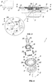
- a multifunction rotary tool generally designated by numeral 1, which is designed to be installed on a bookbinding machine to perform milling and roughening operations on the back D of blocks B of pages S to be bound.
- Such operations have the purpose to increase the surface of the back D of the blocks B that is available for further application of a coat of glue, allowing a flexible cover to be attached to the back D.
- the bookbinding machine comprises a advancement plane P for feeding the blocks B in a substantially horizontal direction L and a motorized spindle 2 with a multifunction tool 1 mounted thereon.
- the block B may be fed by means of a motorized clamp, not shown, whose plates are adapted to retain the block B at its side walls.
- the multifunction tool 1 comprises a cylindrical base 3 defining a substantially vertical axis of rotation V, and adapted to be coupled to the motorized spindle 2 of the machine.
- the cylindrical base 3 may comprise a central hole 4 for receiving the spindle 2 and will be adapted to be coupled thereto by means of a key, as best shown in FIG. 4 or a tongue, a shrink disk, a square shaft, a spline shaft or other similar coupling types.
- cylindrical base 3 has a top surface 5 with first 6 and second 7 sets of radially and angularly offset holes.
- the tool 1 further comprises a first annular member 9 that can be coaxially secured to the cylindrical base 3 and has a substantially circular outer peripheral edge 10.
- the first annular member 9 comprises a crown of milling blades 11 formed at its outer peripheral edge 10 and defining a cutting plane ⁇ substantially perpendicular to the vertical axis of rotation V.
- Each of the blades 11 comprises a front cutting portion 12 and an upper cutting portion 13 which are adapted to remove the material from the back D of the block B as the latter is fed on the surface P of the machine and the cylindrical base 3 is rotated.
- the first annular member 9 may comprise a plurality of through holes 14 that are angularly arranged and can be aligned with the threaded holes 8 of the first set 6, formed on the base to receive screws 15 for removably securing the first annular member 9 to the base 3.
- a second annular member 16 may be provided, whose diameter is smaller than that of the first and can be removably secured to the cylindrical base 3.
- the second annular member 16 may comprise, on its top surface 17, a plurality of brushes 18 that project upwards from the cutting plane ⁇ and are adapted to remove any processing residues from the back D of the blocks B.
- a pair of third central annular members 19, 19' may be provided, for maintaining the annular members 9, 16 coupled with each other and with the base 3, by means of appropriate connecting screws 20.
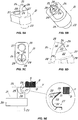
- the multifunctional tool 1 also comprises a plurality of roughening inserts 21, as best shown in FIGS. 5A to 5E , which are adapted to be removably secured to the cylindrical base 3 along a circular area 22 that is radially inwardly offset relative to the crown of milling blades 11.
- the roughening inserts 21 partially project relative to the cutting plane ⁇ of the milling blades 11, as best shown in FIG. 3 , to cut the back D of the block that is being fed on the surface P of the machine as the base 3 is rotated, and may be arranged along circumferences C 1 , C 2 that are substantially concentric with respect to the axis of rotation V.
- the block B that is being fed along the surface P of the bookbinding machine will first interact with the milling blades 11 and then with the roughening inserts 21.
- the roughening inserts 21 may be arranged along further circumferences without departure from the scope of the present invention.
- each roughening insert 21 comprises a cylindrical body 23 with a substantially hook-shaped end portion 24 defined by a substantially straight upper edge 25, as best shown in FIGS. 5A to 5E .
- the upper edge 25 has a sharp tip 26, as best shown in FIGS. 5D and 5R, which is adapted to penetrate the back D of the block B and cut it in a direction Y substantially perpendicular thereto.
- each roughening insert 21 comprises an at least partially curved recessed surface 27, as best shown in FIG. 5D , which is adapted to tear and push downwards the cut material without removing it.
- the multifunctional rotary tool 1 of the invention is able to mill and rough the back D of the blocks B of pages S to be bound while considerably increasing the surface thereof that is available for application and distribution of the glue, without removing any material therefrom, and without damaging the parts of the block B contiguous to the back D, that require no processing.
- each insert 21 may comprise a pair of substantially flat side surfaces 28 which converge toward the upper edge 25 and side edges 29 defined by the intersection of the side surfaces 28 with the recessed surface 27.
- the upper edge 25 is chamfered and has a first section 30 inclined with respect to the cutting plane ⁇ and a second section 31 substantially parallel to the cutting plane ⁇ and defining the sharp tip 26.
- the sharp tip 26 and part of the first inclined section 30 of the upper edge 25 will project relative to the cutting plane ⁇ of the blades 11 to interact with the back D of the block B in the direction Y perpendicular thereto.
- the inclination of the inclined section 30 is selected in such a manner that, as the tool 1 rotates, each insert 21 will only interact with the back D of the block B at the sharp tip 26, thereby preventing shocks and damages to the parts of the block that are not designed to be processed.
- the recessed surface 27 comprises a substantially cylindrical lower portion 32 and a substantially flat and straight upper portion 33, as best shown in FIGS. 5D and 5E .
- the side edges 29 are curved at the lower portion 32 and planar and inclined at the upper portion 33.
- the bevels 34 formed at the upper edge 25 and the side edges 29 of the end portion 24 of each insert 21 eliminate the sharp edges that might cause material removal during roughening of the back D.
- the roughening inserts 21 as used in the present invention carry out notching of the back D of blocks B by tearing the material fibers and pushing the material downwards.
- each insert 21 comprises a support 35 having a generally prismatic shape, possibly with rounded corners, in which the cylindrical body 23 is accommodated and housed in a corresponding through cavity 36 having a mating shape, formed in the first annular member 9.
- the shape of the support 35 and the cavities 36 may also be other than a prismatic shape, without departure from the scope of the present claims.
- the first annular member 35 may comprise a plurality of through holes 37 that are angularly arranged and can be aligned with the threaded holes 8 of the first set 7, formed on the base to receive screws 38 for removably securing the insert member 21 to the base 3.
- This feature greatly simplifies maintenance of the tool 1, as it allows replacement of damaged or worn roughening inserts 21 only, without requiring replacement of a whole crown of inserts, unlike prior art tools.
- the first annular member 9 may comprise at least two series 39, 40 of through cavities 36 that are angularly offset and radially arranged in respective circular paths concentric with the axis of rotation, radially offset and corresponding to the circumferences C 1 , C 2 .
- the tool 1 has an outer series 39 having eight through cavities 36 and an inner series 40 having four through cavities 36, and each of the cavities 36 is adapted to accommodate a respective insert 21 with its corresponding support 35.
- the roughening inserts 21 may be fitted in some of the through cavities 36, according to particular types of notching to be carried out on the back D of blocks B.
- the invention relates to a bookbinding machine, not shown, for binding blocks B of packed pages S, which comprises a advancement plane P for feeding the blocks B in a substantially horizontal direction L and a load unit for loading the blocks B with the back lying on the advancement plane P.
- the machine comprises a motorized spindle 2 with a substantially vertical axis of rotation V having the above described multifunctional rotary tool 1 mounted thereto.
- the tool 1 installed in the bookbinding machine allows the back D of the blocks to be milled using the crown of milling blades 11 and roughed using the plurality of roughening inserts 21 which are adapted to cut the material of the blocks B without removing it.
- the present invention may find application in industry, because it can be produced on an industrial scale in the publishing and bookbinding industries.
Landscapes
- Engineering & Computer Science (AREA)
- Mechanical Engineering (AREA)
- Perforating, Stamping-Out Or Severing By Means Other Than Cutting (AREA)
- Details Of Cutting Devices (AREA)
Claims (11)
- Un outil rotatif multifonction (1) pour machines à relier, en particulier pour fraiser et rendre rugueuse le dos (D) de blocs (B) de pages (S) à relier, dans lequel la machine à relier comprend un plateau (P) d'avancement sensiblement horizontal pour alimenter les blocs (B) et une broche motorisée (2), lequel outil (1) comprend:- une base cylindrique (3) définissant un axe de rotation (V) et adaptée pour être couplée à une broche motorisée (2) de la machine à relier;- un premier élément annulaire (9) conçu pour être fixé de manière coaxiale à ladite base cylindrique (3) et ayant un bord périphérique extérieur sensiblement circulaire (10);- une couronne de lames de fraisage (11) formée dans ledit premier élément annulaire (9) à proximité de son bord périphérique extérieur (10) et définissant un plan de coupe (π) sensiblement perpendiculaire audit axe de rotation (V);- une pluralité d'inserts de rainurage (21), qui sont adaptés pour être fixés de manière amovible à ladite base cylindrique (3) le long d'une zone circulaire (22) qui est décalée radialement vers l'intérieur par rapport à ladite couronne de lames de fraisage (11);caractérisé en ce que chaque insert de rainurage (21) comprend un corps cylindrique (23) avec une partie d'extrémité (24) ayant une forme sensiblement de crochet définie par un bord supérieur (25) avec une pointe acérée (26) qui est conçue pour pénétrer le dos (D) du bloc (B) et le découper suivant une direction (Y) sensiblement perpendiculaire à celui-ci, et une surface creuse au moins partiellement incurvée (27), qui est adapté pour déchirer et pousser vers le bas le matériau coupé sans l'enlever.
- Outil selon la revendication 1, caractérisé en ce que ladite partie d'extrémité (24) comprend une paire de surfaces latérales (28) sensiblement planes qui convergent vers ledit bord supérieur (25) et des bords latéraux (29) définis par l'intersection desdites surfaces latérales (28) avec ladite surface creuse (27).
- Outil selon la revendication 1, caractérisé en ce que ledit bord supérieur (25) est chanfreiné et comporte une première partie (30) inclinée par rapport audit plan de coupe (π) et une deuxième partie (31) sensiblement parallèle audit plan de coupe (π) et définissant ladite pointe acérée (26).
- Outil selon la revendication 2, caractérisé en ce que ladite surface creuse (27) comprend une partie inférieure sensiblement cylindrique (32), qui est reliée à une partie supérieure sensiblement plane et inclinée (33).
- Outil selon la revendication 4, caractérisé en ce que lesdits bords latéraux (29) sont incurvés au niveau de ladite partie inférieure (32) et droits et chanfreinés au niveau de ladite partie supérieure (33).
- Outil selon la revendication 1, caractérisé en ce que lesdits inserts de rainurage (21) sont disposés le long de circonférences (C1, C2) sensiblement concentriques audit axe de rotation (V).
- Outil selon la revendication 6, caractérisé en ce que chaque insert (21) comprend un support substantiellement prismatique (35) dans lequel est inséré ledit corps cylindrique (23), qui est conformé pour être logé dans une cavité traversante correspondante (36) formée dans ledit premier élément annulaire (9), ledit support (35) ayant des trous traversants (37) pour des vis d'ancrage respectives (38).
- Outil selon la revendication 7, caractérisé en ce qu'il comprend au moins deux séries (39, 40) de cavités traversantes (36) qui sont décalées angulairement dans des trajectoires circulaires respectives concentriques audit axe de rotation (V), décalées radialement et correspondantes audites circonférences (C1, C2).
- Outil selon la revendication 7, caractérisé en ce que ladite base (3) comprend un premier ensemble (6) de trous filetés (8) pour des vis d'ancrage (15) destinées à fixer ledit premier élément annulaire (9) à ladite base (3), et un second ensemble (7) de trous filetés (8) alignés avec lesdites cavités traversantes (36) pour fixer lesdits inserts (21) à ladite base (3).
- Outil selon la revendication 1, caractérisé en ce qu 'il comprend un deuxième élément annulaire (16) dont le diamètre est plus étroit que celui du premier élément annulaire (9) et configuré pour être fixé de manière amovible à ladite base cylindrique (3), ledit deuxième élément annulaire (16) ayant une pluralité de brosses (18) faisant saillie vers le haut depuis ledit plan de coupe (π).
- Une machine de reliure pour relier des blocs (B) de pages empilées (P), comprenant un plateau d'avancement (P) pour alimenter les blocs dans une direction sensiblement horizontale (L), une unité de chargement pour charger les blocs (B) avec le dos (D) reposant sur le plateau d'avancement (P), une broche motorisée (2) à axe de rotation sensiblement vertical (V), un outil (1) monté sur ladite broche (2) et des moyens de guidage pour guider les blocs (B) en cours de traitement par intersection dudit axe de rotation (V), caractérisé en ce que ledit outil (1) est un outil multifonctionnel (1) selon une ou plusieurs des revendications 1 à 10, destiné à fraiser le dos (D) des blocs ( B) en utilisant la couronne à lames périphériques (11), et à rendre rugueux le dos (D) des blocs (B) en utilisant ladite pluralité d'inserts de rainurage (21) pour couper le matériau des blocs (B) sans l'enlever.
Applications Claiming Priority (2)
| Application Number | Priority Date | Filing Date | Title |
|---|---|---|---|
| ITUA2016A001988A ITUA20161988A1 (it) | 2016-03-24 | 2016-03-24 | Utensile rotativo multifunzionale per macchine brossuratrici |
| PCT/IB2017/051677 WO2017163206A1 (fr) | 2016-03-24 | 2017-03-23 | Outil rotatif multifonctionnel pour machines à relier, et machine à relier |
Publications (2)
| Publication Number | Publication Date |
|---|---|
| EP3433106A1 EP3433106A1 (fr) | 2019-01-30 |
| EP3433106B1 true EP3433106B1 (fr) | 2020-02-12 |
Family
ID=56235883
Family Applications (1)
| Application Number | Title | Priority Date | Filing Date |
|---|---|---|---|
| EP17724278.1A Active EP3433106B1 (fr) | 2016-03-24 | 2017-03-23 | Outil rotatif multifonctionnel pour machines à relier, et machine à relier |
Country Status (4)
| Country | Link |
|---|---|
| US (1) | US10744809B2 (fr) |
| EP (1) | EP3433106B1 (fr) |
| IT (1) | ITUA20161988A1 (fr) |
| WO (1) | WO2017163206A1 (fr) |
Families Citing this family (1)
| Publication number | Priority date | Publication date | Assignee | Title |
|---|---|---|---|---|
| IT202300007827A1 (it) * | 2023-04-21 | 2024-10-21 | K G S S R L Unipersonale | Dispositivo di fresatura per macchine brossuratrici e macchina brossuratrice provvista di tale dispositivo |
Family Cites Families (10)
| Publication number | Priority date | Publication date | Assignee | Title |
|---|---|---|---|---|
| CH303678A (de) * | 1952-07-30 | 1954-12-15 | Mueller Hans | Verfahren und Vorrichtung zum fadenlosen Einbinden von Büchern. |
| DE2719402A1 (de) * | 1977-04-30 | 1978-11-02 | Rahdener Maschf August | Verfahren zum binden von buechern o.dgl. nach der klebebindetechnik und vorrichtung zur durchfuehrung des verfahrens |
| DE19650851A1 (de) * | 1996-11-27 | 1998-05-28 | B P S Buessenschuett Projekte | Vorrichtung zum Bearbeiten des Rückens von zu bindenden Blattstapeln |
| DE10022836B4 (de) * | 2000-05-10 | 2008-07-10 | Kolbus Gmbh & Co. Kg | Vorrichtung zur Rückenbearbeitung von Buchblocks |
| DE10230054A1 (de) * | 2002-07-04 | 2004-01-22 | Heidelberger Druckmaschinen Ag | Vorrichtung zum Bearbeiten von Seitenkanten von blattförmigen Bedruckstoffen |
| US7736099B2 (en) * | 2005-12-16 | 2010-06-15 | Cole Carbide Industries, Inc. | Gear milling tool with replaceable cutting inserts |
| JP4326543B2 (ja) * | 2006-04-27 | 2009-09-09 | ホリゾン・インターナショナル株式会社 | 無線綴製本処理装置 |
| IL185047A (en) * | 2007-08-05 | 2011-09-27 | Iscar Ltd | Cutting Tools |
| DE102011105033A1 (de) * | 2011-06-20 | 2012-12-20 | Heidelberger Druckmaschinen Ag | Vorrichtung zur Rückenbearbeitung von Buchblocks |
| US20130294854A1 (en) * | 2012-05-02 | 2013-11-07 | Taegutec, Ltd. | Cutting tool assembly |
-
2016
- 2016-03-24 IT ITUA2016A001988A patent/ITUA20161988A1/it unknown
-
2017
- 2017-03-23 WO PCT/IB2017/051677 patent/WO2017163206A1/fr not_active Ceased
- 2017-03-23 EP EP17724278.1A patent/EP3433106B1/fr active Active
- 2017-03-23 US US16/085,764 patent/US10744809B2/en active Active
Non-Patent Citations (1)
| Title |
|---|
| None * |
Also Published As
| Publication number | Publication date |
|---|---|
| EP3433106A1 (fr) | 2019-01-30 |
| ITUA20161988A1 (it) | 2017-09-24 |
| US20190092072A1 (en) | 2019-03-28 |
| WO2017163206A1 (fr) | 2017-09-28 |
| US10744809B2 (en) | 2020-08-18 |
Similar Documents
| Publication | Publication Date | Title |
|---|---|---|
| EP2623240B1 (fr) | Outil de coupe à tranchants échangeables | |
| US8573903B2 (en) | Round cutting insert with anti-rotation feature | |
| EP2440351B1 (fr) | Outil de coupe et plaquette de coupe correspondante | |
| KR101677917B1 (ko) | 탄소섬유 강화 플라스틱과 같은 섬유 강화 재료의 처리를 위한 엔드밀링 커터 | |
| US20120189393A1 (en) | Modular drill with diamond cutting edges | |
| US20220362960A1 (en) | Accessory for oscillating power tool | |
| JP6006829B2 (ja) | 面取りブレードおよび面取りカッター | |
| CN102240826A (zh) | 用于铣削刀具的可转位铣削刀片 | |
| EP3907030B1 (fr) | Insert de coupe | |
| EP0321391B1 (fr) | Outil de rabotage pour une machine de travail du bois | |
| US20140294524A1 (en) | Pentagon-shaped cutting insert and slotting cutter therefor | |
| JP3777043B2 (ja) | 丸駒型スローアウェイチップを用いた切削工具 | |
| EP3433106B1 (fr) | Outil rotatif multifonctionnel pour machines à relier, et machine à relier | |
| US10744577B2 (en) | Cutting insert positioning cartridge and system for a machining tool and a machining tool comprising such a positioning system | |
| EP3052326B1 (fr) | Plaque de support pour mandrins concentriques | |
| US3300834A (en) | Milling cutter tool | |
| EP1237671B1 (fr) | Fraise a rainurer | |
| GB2079656A (en) | Rotary cutting tools with plural cutting blades | |
| EP2131984B1 (fr) | Insert de coupe indexable et procédé d'usinage | |
| EP4461552B1 (fr) | Dispositif d'encochage pour machines à relier | |
| JP2016032860A (ja) | 切削インサートおよび刃先交換式切削工具 | |
| CN212288929U (zh) | 一种刀具及刀具组件 | |
| EP4450293A1 (fr) | Dispositif de fraisage pour machines à relier et machine à relier comportant un tel dispositif | |
| JP4353068B2 (ja) | 切削ヘッド交換式切削工具 | |
| JP5233362B2 (ja) | インサートクランプ用クサビおよびインサート着脱式カッタ |
Legal Events
| Date | Code | Title | Description |
|---|---|---|---|
| STAA | Information on the status of an ep patent application or granted ep patent |
Free format text: STATUS: UNKNOWN |
|
| STAA | Information on the status of an ep patent application or granted ep patent |
Free format text: STATUS: THE INTERNATIONAL PUBLICATION HAS BEEN MADE |
|
| PUAI | Public reference made under article 153(3) epc to a published international application that has entered the european phase |
Free format text: ORIGINAL CODE: 0009012 |
|
| STAA | Information on the status of an ep patent application or granted ep patent |
Free format text: STATUS: REQUEST FOR EXAMINATION WAS MADE |
|
| 17P | Request for examination filed |
Effective date: 20181008 |
|
| AK | Designated contracting states |
Kind code of ref document: A1 Designated state(s): AL AT BE BG CH CY CZ DE DK EE ES FI FR GB GR HR HU IE IS IT LI LT LU LV MC MK MT NL NO PL PT RO RS SE SI SK SM TR |
|
| AX | Request for extension of the european patent |
Extension state: BA ME |
|
| GRAP | Despatch of communication of intention to grant a patent |
Free format text: ORIGINAL CODE: EPIDOSNIGR1 |
|
| STAA | Information on the status of an ep patent application or granted ep patent |
Free format text: STATUS: GRANT OF PATENT IS INTENDED |
|
| DAV | Request for validation of the european patent (deleted) | ||
| DAX | Request for extension of the european patent (deleted) | ||
| INTG | Intention to grant announced |
Effective date: 20190415 |
|
| INTC | Intention to grant announced (deleted) | ||
| GRAP | Despatch of communication of intention to grant a patent |
Free format text: ORIGINAL CODE: EPIDOSNIGR1 |
|
| INTG | Intention to grant announced |
Effective date: 20190729 |
|
| GRAS | Grant fee paid |
Free format text: ORIGINAL CODE: EPIDOSNIGR3 |
|
| GRAA | (expected) grant |
Free format text: ORIGINAL CODE: 0009210 |
|
| STAA | Information on the status of an ep patent application or granted ep patent |
Free format text: STATUS: THE PATENT HAS BEEN GRANTED |
|
| AK | Designated contracting states |
Kind code of ref document: B1 Designated state(s): AL AT BE BG CH CY CZ DE DK EE ES FI FR GB GR HR HU IE IS IT LI LT LU LV MC MK MT NL NO PL PT RO RS SE SI SK SM TR |
|
| REG | Reference to a national code |
Ref country code: GB Ref legal event code: FG4D |
|
| REG | Reference to a national code |
Ref country code: CH Ref legal event code: EP |
|
| REG | Reference to a national code |
Ref country code: AT Ref legal event code: REF Ref document number: 1231594 Country of ref document: AT Kind code of ref document: T Effective date: 20200215 |
|
| REG | Reference to a national code |
Ref country code: DE Ref legal event code: R096 Ref document number: 602017011692 Country of ref document: DE |
|
| REG | Reference to a national code |
Ref country code: IE Ref legal event code: FG4D |
|
| REG | Reference to a national code |
Ref country code: SE Ref legal event code: TRGR |
|
| PG25 | Lapsed in a contracting state [announced via postgrant information from national office to epo] |
Ref country code: FI Free format text: LAPSE BECAUSE OF FAILURE TO SUBMIT A TRANSLATION OF THE DESCRIPTION OR TO PAY THE FEE WITHIN THE PRESCRIBED TIME-LIMIT Effective date: 20200212 Ref country code: RS Free format text: LAPSE BECAUSE OF FAILURE TO SUBMIT A TRANSLATION OF THE DESCRIPTION OR TO PAY THE FEE WITHIN THE PRESCRIBED TIME-LIMIT Effective date: 20200212 Ref country code: NO Free format text: LAPSE BECAUSE OF FAILURE TO SUBMIT A TRANSLATION OF THE DESCRIPTION OR TO PAY THE FEE WITHIN THE PRESCRIBED TIME-LIMIT Effective date: 20200512 |
|
| REG | Reference to a national code |
Ref country code: LT Ref legal event code: MG4D |
|
| REG | Reference to a national code |
Ref country code: NL Ref legal event code: MP Effective date: 20200212 |
|
| PG25 | Lapsed in a contracting state [announced via postgrant information from national office to epo] |
Ref country code: BG Free format text: LAPSE BECAUSE OF FAILURE TO SUBMIT A TRANSLATION OF THE DESCRIPTION OR TO PAY THE FEE WITHIN THE PRESCRIBED TIME-LIMIT Effective date: 20200512 Ref country code: IS Free format text: LAPSE BECAUSE OF FAILURE TO SUBMIT A TRANSLATION OF THE DESCRIPTION OR TO PAY THE FEE WITHIN THE PRESCRIBED TIME-LIMIT Effective date: 20200612 Ref country code: LV Free format text: LAPSE BECAUSE OF FAILURE TO SUBMIT A TRANSLATION OF THE DESCRIPTION OR TO PAY THE FEE WITHIN THE PRESCRIBED TIME-LIMIT Effective date: 20200212 Ref country code: GR Free format text: LAPSE BECAUSE OF FAILURE TO SUBMIT A TRANSLATION OF THE DESCRIPTION OR TO PAY THE FEE WITHIN THE PRESCRIBED TIME-LIMIT Effective date: 20200513 Ref country code: HR Free format text: LAPSE BECAUSE OF FAILURE TO SUBMIT A TRANSLATION OF THE DESCRIPTION OR TO PAY THE FEE WITHIN THE PRESCRIBED TIME-LIMIT Effective date: 20200212 |
|
| PG25 | Lapsed in a contracting state [announced via postgrant information from national office to epo] |
Ref country code: NL Free format text: LAPSE BECAUSE OF FAILURE TO SUBMIT A TRANSLATION OF THE DESCRIPTION OR TO PAY THE FEE WITHIN THE PRESCRIBED TIME-LIMIT Effective date: 20200212 |
|
| PG25 | Lapsed in a contracting state [announced via postgrant information from national office to epo] |
Ref country code: ES Free format text: LAPSE BECAUSE OF FAILURE TO SUBMIT A TRANSLATION OF THE DESCRIPTION OR TO PAY THE FEE WITHIN THE PRESCRIBED TIME-LIMIT Effective date: 20200212 Ref country code: DK Free format text: LAPSE BECAUSE OF FAILURE TO SUBMIT A TRANSLATION OF THE DESCRIPTION OR TO PAY THE FEE WITHIN THE PRESCRIBED TIME-LIMIT Effective date: 20200212 Ref country code: SK Free format text: LAPSE BECAUSE OF FAILURE TO SUBMIT A TRANSLATION OF THE DESCRIPTION OR TO PAY THE FEE WITHIN THE PRESCRIBED TIME-LIMIT Effective date: 20200212 Ref country code: SM Free format text: LAPSE BECAUSE OF FAILURE TO SUBMIT A TRANSLATION OF THE DESCRIPTION OR TO PAY THE FEE WITHIN THE PRESCRIBED TIME-LIMIT Effective date: 20200212 Ref country code: EE Free format text: LAPSE BECAUSE OF FAILURE TO SUBMIT A TRANSLATION OF THE DESCRIPTION OR TO PAY THE FEE WITHIN THE PRESCRIBED TIME-LIMIT Effective date: 20200212 Ref country code: CZ Free format text: LAPSE BECAUSE OF FAILURE TO SUBMIT A TRANSLATION OF THE DESCRIPTION OR TO PAY THE FEE WITHIN THE PRESCRIBED TIME-LIMIT Effective date: 20200212 Ref country code: PT Free format text: LAPSE BECAUSE OF FAILURE TO SUBMIT A TRANSLATION OF THE DESCRIPTION OR TO PAY THE FEE WITHIN THE PRESCRIBED TIME-LIMIT Effective date: 20200705 Ref country code: RO Free format text: LAPSE BECAUSE OF FAILURE TO SUBMIT A TRANSLATION OF THE DESCRIPTION OR TO PAY THE FEE WITHIN THE PRESCRIBED TIME-LIMIT Effective date: 20200212 Ref country code: LT Free format text: LAPSE BECAUSE OF FAILURE TO SUBMIT A TRANSLATION OF THE DESCRIPTION OR TO PAY THE FEE WITHIN THE PRESCRIBED TIME-LIMIT Effective date: 20200212 |
|
| REG | Reference to a national code |
Ref country code: DE Ref legal event code: R097 Ref document number: 602017011692 Country of ref document: DE |
|
| REG | Reference to a national code |
Ref country code: AT Ref legal event code: MK05 Ref document number: 1231594 Country of ref document: AT Kind code of ref document: T Effective date: 20200212 |
|
| PG25 | Lapsed in a contracting state [announced via postgrant information from national office to epo] |
Ref country code: MC Free format text: LAPSE BECAUSE OF FAILURE TO SUBMIT A TRANSLATION OF THE DESCRIPTION OR TO PAY THE FEE WITHIN THE PRESCRIBED TIME-LIMIT Effective date: 20200212 |
|
| PLBE | No opposition filed within time limit |
Free format text: ORIGINAL CODE: 0009261 |
|
| STAA | Information on the status of an ep patent application or granted ep patent |
Free format text: STATUS: NO OPPOSITION FILED WITHIN TIME LIMIT |
|
| REG | Reference to a national code |
Ref country code: BE Ref legal event code: MM Effective date: 20200331 |
|
| PG25 | Lapsed in a contracting state [announced via postgrant information from national office to epo] |
Ref country code: LU Free format text: LAPSE BECAUSE OF NON-PAYMENT OF DUE FEES Effective date: 20200323 |
|
| 26N | No opposition filed |
Effective date: 20201113 |
|
| PG25 | Lapsed in a contracting state [announced via postgrant information from national office to epo] |
Ref country code: AT Free format text: LAPSE BECAUSE OF FAILURE TO SUBMIT A TRANSLATION OF THE DESCRIPTION OR TO PAY THE FEE WITHIN THE PRESCRIBED TIME-LIMIT Effective date: 20200212 |
|
| PG25 | Lapsed in a contracting state [announced via postgrant information from national office to epo] |
Ref country code: BE Free format text: LAPSE BECAUSE OF NON-PAYMENT OF DUE FEES Effective date: 20200331 Ref country code: SI Free format text: LAPSE BECAUSE OF FAILURE TO SUBMIT A TRANSLATION OF THE DESCRIPTION OR TO PAY THE FEE WITHIN THE PRESCRIBED TIME-LIMIT Effective date: 20200212 Ref country code: PL Free format text: LAPSE BECAUSE OF FAILURE TO SUBMIT A TRANSLATION OF THE DESCRIPTION OR TO PAY THE FEE WITHIN THE PRESCRIBED TIME-LIMIT Effective date: 20200212 |
|
| PGFP | Annual fee paid to national office [announced via postgrant information from national office to epo] |
Ref country code: IE Payment date: 20220321 Year of fee payment: 6 Ref country code: CH Payment date: 20220324 Year of fee payment: 6 |
|
| PG25 | Lapsed in a contracting state [announced via postgrant information from national office to epo] |
Ref country code: TR Free format text: LAPSE BECAUSE OF FAILURE TO SUBMIT A TRANSLATION OF THE DESCRIPTION OR TO PAY THE FEE WITHIN THE PRESCRIBED TIME-LIMIT Effective date: 20200212 Ref country code: MT Free format text: LAPSE BECAUSE OF FAILURE TO SUBMIT A TRANSLATION OF THE DESCRIPTION OR TO PAY THE FEE WITHIN THE PRESCRIBED TIME-LIMIT Effective date: 20200212 Ref country code: CY Free format text: LAPSE BECAUSE OF FAILURE TO SUBMIT A TRANSLATION OF THE DESCRIPTION OR TO PAY THE FEE WITHIN THE PRESCRIBED TIME-LIMIT Effective date: 20200212 |
|
| PGFP | Annual fee paid to national office [announced via postgrant information from national office to epo] |
Ref country code: SE Payment date: 20220324 Year of fee payment: 6 |
|
| PG25 | Lapsed in a contracting state [announced via postgrant information from national office to epo] |
Ref country code: MK Free format text: LAPSE BECAUSE OF FAILURE TO SUBMIT A TRANSLATION OF THE DESCRIPTION OR TO PAY THE FEE WITHIN THE PRESCRIBED TIME-LIMIT Effective date: 20200212 Ref country code: AL Free format text: LAPSE BECAUSE OF FAILURE TO SUBMIT A TRANSLATION OF THE DESCRIPTION OR TO PAY THE FEE WITHIN THE PRESCRIBED TIME-LIMIT Effective date: 20200212 |
|
| P01 | Opt-out of the competence of the unified patent court (upc) registered |
Effective date: 20230606 |
|
| REG | Reference to a national code |
Ref country code: CH Ref legal event code: PL Ref country code: SE Ref legal event code: EUG |
|
| REG | Reference to a national code |
Ref country code: IE Ref legal event code: MM4A |
|
| PG25 | Lapsed in a contracting state [announced via postgrant information from national office to epo] |
Ref country code: SE Free format text: LAPSE BECAUSE OF NON-PAYMENT OF DUE FEES Effective date: 20230324 Ref country code: LI Free format text: LAPSE BECAUSE OF NON-PAYMENT OF DUE FEES Effective date: 20230331 Ref country code: IE Free format text: LAPSE BECAUSE OF NON-PAYMENT OF DUE FEES Effective date: 20230323 Ref country code: CH Free format text: LAPSE BECAUSE OF NON-PAYMENT OF DUE FEES Effective date: 20230331 |
|
| PGFP | Annual fee paid to national office [announced via postgrant information from national office to epo] |
Ref country code: GB Payment date: 20260304 Year of fee payment: 10 |
|
| PGFP | Annual fee paid to national office [announced via postgrant information from national office to epo] |
Ref country code: DE Payment date: 20260320 Year of fee payment: 10 |
|
| PGFP | Annual fee paid to national office [announced via postgrant information from national office to epo] |
Ref country code: IT Payment date: 20260320 Year of fee payment: 10 |
|
| PGFP | Annual fee paid to national office [announced via postgrant information from national office to epo] |
Ref country code: FR Payment date: 20260323 Year of fee payment: 10 |