EP3433482B1 - Unité formant injecteur de carburant, agencement d'alimentation en carburant et moteur à combustion interne à piston - Google Patents
Unité formant injecteur de carburant, agencement d'alimentation en carburant et moteur à combustion interne à piston Download PDFInfo
- Publication number
- EP3433482B1 EP3433482B1 EP16713507.8A EP16713507A EP3433482B1 EP 3433482 B1 EP3433482 B1 EP 3433482B1 EP 16713507 A EP16713507 A EP 16713507A EP 3433482 B1 EP3433482 B1 EP 3433482B1
- Authority
- EP
- European Patent Office
- Prior art keywords
- fuel
- control
- valve
- pressure
- injector unit
- Prior art date
- Legal status (The legal status is an assumption and is not a legal conclusion. Google has not performed a legal analysis and makes no representation as to the accuracy of the status listed.)
- Active
Links
Images


Classifications
-
- F—MECHANICAL ENGINEERING; LIGHTING; HEATING; WEAPONS; BLASTING
- F02—COMBUSTION ENGINES; HOT-GAS OR COMBUSTION-PRODUCT ENGINE PLANTS
- F02M—SUPPLYING COMBUSTION ENGINES IN GENERAL WITH COMBUSTIBLE MIXTURES OR CONSTITUENTS THEREOF
- F02M43/00—Fuel-injection apparatus operating simultaneously on two or more fuels, or on a liquid fuel and another liquid, e.g. the other liquid being an anti-knock additive
- F02M43/04—Injectors peculiar thereto
-
- F—MECHANICAL ENGINEERING; LIGHTING; HEATING; WEAPONS; BLASTING
- F02—COMBUSTION ENGINES; HOT-GAS OR COMBUSTION-PRODUCT ENGINE PLANTS
- F02D—CONTROLLING COMBUSTION ENGINES
- F02D19/00—Controlling engines characterised by their use of non-liquid fuels, pluralities of fuels, or non-fuel substances added to the combustible mixtures
- F02D19/06—Controlling engines characterised by their use of non-liquid fuels, pluralities of fuels, or non-fuel substances added to the combustible mixtures peculiar to engines working with pluralities of fuels, e.g. alternatively with light and heavy fuel oil, other than engines indifferent to the fuel consumed
- F02D19/0639—Controlling engines characterised by their use of non-liquid fuels, pluralities of fuels, or non-fuel substances added to the combustible mixtures peculiar to engines working with pluralities of fuels, e.g. alternatively with light and heavy fuel oil, other than engines indifferent to the fuel consumed characterised by the type of fuels
- F02D19/0642—Controlling engines characterised by their use of non-liquid fuels, pluralities of fuels, or non-fuel substances added to the combustible mixtures peculiar to engines working with pluralities of fuels, e.g. alternatively with light and heavy fuel oil, other than engines indifferent to the fuel consumed characterised by the type of fuels at least one fuel being gaseous, the other fuels being gaseous or liquid at standard conditions
- F02D19/0647—Controlling engines characterised by their use of non-liquid fuels, pluralities of fuels, or non-fuel substances added to the combustible mixtures peculiar to engines working with pluralities of fuels, e.g. alternatively with light and heavy fuel oil, other than engines indifferent to the fuel consumed characterised by the type of fuels at least one fuel being gaseous, the other fuels being gaseous or liquid at standard conditions the gaseous fuel being liquefied petroleum gas [LPG], liquefied natural gas [LNG], compressed natural gas [CNG] or dimethyl ether [DME]
-
- F—MECHANICAL ENGINEERING; LIGHTING; HEATING; WEAPONS; BLASTING
- F02—COMBUSTION ENGINES; HOT-GAS OR COMBUSTION-PRODUCT ENGINE PLANTS
- F02D—CONTROLLING COMBUSTION ENGINES
- F02D19/00—Controlling engines characterised by their use of non-liquid fuels, pluralities of fuels, or non-fuel substances added to the combustible mixtures
- F02D19/06—Controlling engines characterised by their use of non-liquid fuels, pluralities of fuels, or non-fuel substances added to the combustible mixtures peculiar to engines working with pluralities of fuels, e.g. alternatively with light and heavy fuel oil, other than engines indifferent to the fuel consumed
- F02D19/0663—Details on the fuel supply system, e.g. tanks, valves, pipes, pumps, rails, injectors or mixers
- F02D19/0686—Injectors
- F02D19/0692—Arrangement of multiple injectors per combustion chamber
-
- F—MECHANICAL ENGINEERING; LIGHTING; HEATING; WEAPONS; BLASTING
- F02—COMBUSTION ENGINES; HOT-GAS OR COMBUSTION-PRODUCT ENGINE PLANTS
- F02M—SUPPLYING COMBUSTION ENGINES IN GENERAL WITH COMBUSTIBLE MIXTURES OR CONSTITUENTS THEREOF
- F02M21/00—Apparatus for supplying engines with non-liquid fuels, e.g. gaseous fuels stored in liquid form
- F02M21/02—Apparatus for supplying engines with non-liquid fuels, e.g. gaseous fuels stored in liquid form for gaseous fuels
- F02M21/0218—Details on the gaseous fuel supply system, e.g. tanks, valves, pipes, pumps, rails, injectors or mixers
-
- F—MECHANICAL ENGINEERING; LIGHTING; HEATING; WEAPONS; BLASTING
- F02—COMBUSTION ENGINES; HOT-GAS OR COMBUSTION-PRODUCT ENGINE PLANTS
- F02M—SUPPLYING COMBUSTION ENGINES IN GENERAL WITH COMBUSTIBLE MIXTURES OR CONSTITUENTS THEREOF
- F02M37/00—Apparatus or systems for feeding liquid fuel from storage containers to carburettors or fuel-injection apparatus; Arrangements for purifying liquid fuel specially adapted for, or arranged on, internal-combustion engines
- F02M37/0047—Layout or arrangement of systems for feeding fuel
- F02M37/0064—Layout or arrangement of systems for feeding fuel for engines being fed with multiple fuels or fuels having special properties, e.g. bio-fuels; varying the fuel composition
-
- F—MECHANICAL ENGINEERING; LIGHTING; HEATING; WEAPONS; BLASTING
- F02—COMBUSTION ENGINES; HOT-GAS OR COMBUSTION-PRODUCT ENGINE PLANTS
- F02M—SUPPLYING COMBUSTION ENGINES IN GENERAL WITH COMBUSTIBLE MIXTURES OR CONSTITUENTS THEREOF
- F02M43/00—Fuel-injection apparatus operating simultaneously on two or more fuels, or on a liquid fuel and another liquid, e.g. the other liquid being an anti-knock additive
-
- F—MECHANICAL ENGINEERING; LIGHTING; HEATING; WEAPONS; BLASTING
- F02—COMBUSTION ENGINES; HOT-GAS OR COMBUSTION-PRODUCT ENGINE PLANTS
- F02M—SUPPLYING COMBUSTION ENGINES IN GENERAL WITH COMBUSTIBLE MIXTURES OR CONSTITUENTS THEREOF
- F02M47/00—Fuel-injection apparatus operated cyclically with fuel-injection valves actuated by fluid pressure
- F02M47/02—Fuel-injection apparatus operated cyclically with fuel-injection valves actuated by fluid pressure of accumulator-injector type, i.e. having fuel pressure of accumulator tending to open, and fuel pressure in other chamber tending to close, injection valves and having means for periodically releasing that closing pressure
- F02M47/027—Electrically actuated valves draining the chamber to release the closing pressure
-
- F—MECHANICAL ENGINEERING; LIGHTING; HEATING; WEAPONS; BLASTING
- F02—COMBUSTION ENGINES; HOT-GAS OR COMBUSTION-PRODUCT ENGINE PLANTS
- F02M—SUPPLYING COMBUSTION ENGINES IN GENERAL WITH COMBUSTIBLE MIXTURES OR CONSTITUENTS THEREOF
- F02M63/00—Other fuel-injection apparatus having pertinent characteristics not provided for in groups F02M39/00 - F02M57/00 or F02M67/00; Details, component parts, or accessories of fuel-injection apparatus, not provided for in, or of interest apart from, the apparatus of groups F02M39/00 - F02M61/00 or F02M67/00; Combination of fuel pump with other devices, e.g. lubricating oil pump
- F02M63/02—Fuel-injection apparatus having several injectors fed by a common pumping element, or having several pumping elements feeding a common injector; Fuel-injection apparatus having provisions for cutting-out pumps, pumping elements, or injectors; Fuel-injection apparatus having provisions for variably interconnecting pumping elements and injectors alternatively
- F02M63/0205—Fuel-injection apparatus having several injectors fed by a common pumping element, or having several pumping elements feeding a common injector; Fuel-injection apparatus having provisions for cutting-out pumps, pumping elements, or injectors; Fuel-injection apparatus having provisions for variably interconnecting pumping elements and injectors alternatively for cutting-out pumps or injectors in case of abnormal operation of the engine or the injection apparatus, e.g. over-speed, break-down of fuel pumps or injectors ; for cutting-out pumps for stopping the engine
- F02M63/0215—Fuel-injection apparatus having several injectors fed by a common pumping element, or having several pumping elements feeding a common injector; Fuel-injection apparatus having provisions for cutting-out pumps, pumping elements, or injectors; Fuel-injection apparatus having provisions for variably interconnecting pumping elements and injectors alternatively for cutting-out pumps or injectors in case of abnormal operation of the engine or the injection apparatus, e.g. over-speed, break-down of fuel pumps or injectors ; for cutting-out pumps for stopping the engine by draining or closing fuel conduits
-
- Y—GENERAL TAGGING OF NEW TECHNOLOGICAL DEVELOPMENTS; GENERAL TAGGING OF CROSS-SECTIONAL TECHNOLOGIES SPANNING OVER SEVERAL SECTIONS OF THE IPC; TECHNICAL SUBJECTS COVERED BY FORMER USPC CROSS-REFERENCE ART COLLECTIONS [XRACs] AND DIGESTS
- Y02—TECHNOLOGIES OR APPLICATIONS FOR MITIGATION OR ADAPTATION AGAINST CLIMATE CHANGE
- Y02T—CLIMATE CHANGE MITIGATION TECHNOLOGIES RELATED TO TRANSPORTATION
- Y02T10/00—Road transport of goods or passengers
- Y02T10/10—Internal combustion engine [ICE] based vehicles
- Y02T10/30—Use of alternative fuels, e.g. biofuels
Definitions
- the present invention relates to a fuel injector unit for assembly to a cylinder head of an internal combustion piston engine and for injecting first and second fuel to a cylinder of the internal combustion piston engine according to the preamble of claim 1.
- the present invention relates also a fuel feeding arrangement and to an internal combustion piston engine comprising a fuel injector unit.
- Internal combustion engines are generally provided with fuel injection systems in which the provision of pressurize the fuel and the control of injection are functionally separated from each other.
- Fuel is fed by means of at least one high pressure fuel pump into a pressure accumulator, i.e. rail, from which the fuel is led through separate conduits into the injector or injection valve of each cylinder.
- a pressure accumulator i.e. rail
- These systems are commonly known as common rail fuel injection systems.
- the pressure, timing of the injection, duration of the injection and quantity of the fuel supplied into the nozzle of the injector has also an impact on the quantity and quality of the combustion gases (pollutants, emissions%) generated by the combustion process.
- the operation of a fuel injector is electronically controlled, for example, by means of a hydraulic control system with a solenoid or piezoelectric valve, in order to obtain a sufficiently short and accurate injection.
- the control of the injection valve, or specifically the injection needle valve is typically accomplished by making use of the fuel pressure acting against surface of the needle valve in a direction of opening and/or closing the needle valve, depending on the case.
- the injection pressure reaches high pressure level almost immediately when the needle valve starts moving (rising) away from its closed position in the injector nozzle.
- a gaseous fuel such as natural gas
- a liquid fuel such as LFO or diesel fuel oil
- EP 0778410 A1 discloses an injection valve arrangement for an internal combustion engine.
- the arrangement comprises first valve means in the form of at least two needle valves for injecting gaseous fuel directly into a cylinder of the engine.
- the arrangement further comprises second valve means in the form of a needle valve for injecting pilot fuel into the cylinder so as to enrich the mixture therein for ignition.
- Control of the operation of the gas needle valves is arranged by means of a common control valve preferably under electronic control.
- the valve needles of the gas needle valves are mechanically connected to each other so that the movements thereof occur concurrently.
- WO 2014/167166 A1 discloses a fuel injection unit for assembly to a cylinder head and for injecting first and second fuel to a cylinder of an internal combustion piston engine.
- the fuel injection unit comprises a first fuel feeding section, a second fuel feeding section, a pressure accumulator in the first fuel feeding section and a flow fuse valve arranged in the first fuel feeding section between the pressure accumulator and a fuel injection valve of the first fuel feeding section.
- the fuel injection valve comprises a fuel handling section and control section wherein the control section is a hydraulic control section fluidly separated from the fuel handling section.
- WO 2015/090494 A1 discloses a dual fuel injector for a fuel injection device.
- the dual fuel injector comprises a liquid fuel injector unit with a nozzle needle assigned to a liquid fuel nozzle arrangement of the dual fuel injector and which is stroke controllable via a first control chamber.
- the dual fuel injector further comprises a gas injector unit with a gas nozzle needle assigned to a gas nozzle arrangement of the dual fuel injector and which is stroke controllable via a second control chamber.
- Each of the first and second control chambers can be impinged with a control fluid in order to control the stroke of the respective nozzle needle.
- the control fluid from both the first and the second control chambers can be discharged.
- the dual fuel injector has a control fluid reservoir in which discharged control fluid from the first control chamber can be introduced.
- the dual fuel injector is configured to impinge the second control chamber with control fluid from the control fluid reservoir for the stroke of the gas nozzle needle.
- US 2013319373 A1 discloses a dual fuel injector in a dual common rail fuel system.
- the dual fuel injector includes an injector body defining a liquid fuel supply passage to a liquid fuel nozzle outlet and a gaseous fuel supply passage to a gaseous fuel nozzle outlet.
- a liquid fuel needle check is movable within the injector body and has an opening hydraulic surface exposed to a fuel pressure of a liquid fuel common rail.
- a gaseous fuel needle check is positioned side by side with the liquid fuel needle check and has an opening hydraulic surface exposed to the fuel pressure of the liquid fuel common rail.
- An object of the invention is to provide a fuel injector unit in which the performance is considerably improved compared to the prior art solutions.
- a fuel injector unit for assembly to a cylinder head of an internal combustion piston engine and for injecting first and second fuel to the internal combustion piston engine comprises all the features of claim 1.
- sealing fluid chamber arranged between the first control section and the first fuel gallery of the first fuel injection valve, and that the sealing fluid chamber is arranged in flow communication with the second fuel feeding section such that the second fuel is arranged to act as sealing fluid minimizing the first fuel to flow from the first fuel gallery to the first control section.
- This provides a fuel injector unit for an internal combustion piston engine which performance is considerably improved.
- it is possible to use a unique mixture of multiple fuels with one concept such as fuels with ultra-low viscosities, liquid gases, liquid alcohols (e.g. methanol, MeOH) or light fuel oil (LFO).
- Invention gives benefits for all liquefied gases, toxic fuels or easily evaporating fuels which are not desirable to leak out from the fuel injector or more specifically from the first fuel injection valve.
- This sealing strategy provides more reliable sealing of toxic and harmful fuel in emergency shutdowns.
- ultra-low viscosity fuel we mean fuels which have kinematic viscosity in the range of 0,1 ⁇ 10 -6 - 1 ⁇ 10 -6 m 2 /s or less.
- the invention is feasible in using methanol.
- the viscosity of methanol (0-100°C) is 0,29 ⁇ 10 -6 - 1 ⁇ 10 -6 m 2 /s
- the sealing fluid chamber is arranged in flow communication with the second fuel feeding section via a pressure control valve.
- sealing fluid pressure is reduced to close to the first fuel pressure with the pressure control valve i.e. a pressure reduction valve to avoid excess leakage to first fuel side.
- the pressure control valve is adapted maintain a pressure in the sealing fluid chamber in response to the pressure of the first fuel.
- the second fuel feeding section comprises a second fuel injection valve, a second fuel gallery and a second control section wherein position of the second injection valve is effected by a pressure of the second fuel in the second control section, and that the second fuel feeding section is provided with a flow fuse valve arranged between the second fuel inlet and the second fuel injection valve.
- the second injection valve is provided with an injector needle which controls an injection of second fuel to the combustion chamber.
- the position of the injector needle of the second injection valve is effected by a pressure of the second fuel in the second control section so that the pressurized second fuel urges the injector needle of the second fuel injection valve towards its closed position and by reducing the pressure the fuel injector needle of the second fuel injection valve is allowed to move away from its closed position.
- the flow fuse valve is arranged to open and close flow communication from the second fuel inlet via a second fuel channel to the sealing chamber of the first fuel feeding section.
- the first control section of the first fuel feeding section is a hydraulic control section fluidly separated from the first fuel gallery and provided with a control oil inlet.
- the term "fluidly separated" means that the first fuel in the first fuel gallery and the control fluid in the first control section are not substantially or intentionally mixed with each other.
- the sealing fluid chamber is provided with a discharge conduit for allowing a discharge of the second fuel therefrom so as to maintaining adequate pressure in the sealing fluid chamber.
- the first fuel feeding section is provided with a first pressure accumulator arranged upstream the main flow fuse valve in the injector unit.
- the second fuel feeding section is provided with a second fuel accumulator in the injector unit.
- the pressure control valve is provided with a pressure detecting channel leading from the first fuel channel to the pressure control valve.
- the pressure control valve is provided with a pressure detecting channel leading from a third branch downstream of the pressure control valve to the pressure control valve.
- a fuel feeding arrangement comprising a first fuel system with at least one high pressure fuel pump which is arranged to pressurize the first fuel to the injection pressure, and a second fuel system with at least one pump which is arranged to pressurize the second fuel to the injection pressure. It is characteristic to the invention that the arrangement comprises a fuel injector unit according to anyone of claims 1-10 wherein the second fuel pressurized by the at least one pump is arranged as sealing fluid to the sealing fluid chamber of the first fuel feeding section so as to minimize the first fuel to flow from the first fuel gallery to the first control section.
- the first control section is provided with a flow channel arranged to extend from an external control fluid source to the control chamber, which flow channel is provided with a valve so as to open or close flow communication from the external control fluid source to the control chamber.
- Another object of the invention is met by an internal combustion piston engine comprising a fuel injector unit according to anyone of claims 1-12.
- the fuel pressure in the second fuel system pressure must be maintained higher than the fuel pressure in the first fuel system to have the sealing fluid system to operate as intended.
- the pressure difference may be for example 5 MPa - 20MPa.
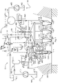
- Figure 1 depicts schematically a fuel feeding arrangement 10 in an internal combustion piston engine 100, which engine 100 is depicted only by a schematic partial presentation of a cylinder 110 and a cylinder head 120.
- the fuel feeding arrangement 10 comprises a first fuel system 400 with at least one high pressure fuel pump 405 which is arranged to pressurize the first fuel to the injection pressure, and a second fuel system 600 with at least one pump 605 which is arranged to pressurize the second fuel to the injection pressure.
- Figure 1 illustrates a first fuel source 402 arranged in flow communication with the pump 405.
- Figure 1 illustrates also a second fuel source 602 arranged in flow communication with the pump 605.
- the fuel feeding arrangement 10 further comprises a fuel injector unit 20 for assembly to the cylinder head 120 of the internal combustion piston engine 100 and for injecting first and second fuel to the internal combustion piston engine 100.
- the fuel injector unit 20 comprises a body 25 which can be removably assembled to the cylinder head 120 of the internal combustion piston engine 100.
- phantom line illustrates a border of the fuel injector unit 20.
- the fuel injector unit 20 can be easily retrofitted to the engine 100.
- the fuel injector unit 20 comprises two fuel feeding sections: a first fuel feeding section 410 and a second fuel feeding section 610.
- the first fuel feeding section 410 is coupled to the first fuel system 400 of the engine 100.
- the second fuel feeding section 610 is coupled to the second fuel system 600 of the engine 100.
- the first fuel system 400 is arranged to feed liquefied gaseous fuel and the second fuel system is arranged to feed liquid fuel.
- the first fuel system 400 feeds alcoholic based fuel such as methanol or other ultra-low viscosity or liquid gas fuel
- the second fuel system 600 feeds pilot fuel, such as diesel fuel, i.e. ignition fuel for compression ignition purposes.
- the first fuel is called as a main fuel and the second fuel as a pilot fuel. Both fuels are injected to the combustion chamber e.g. cylinder 112 of the engine 100 via the same fuel injector unit 20.
- the first fuel feeding section 410 comprises at least one first fuel injection valve 442 for controlling injection of first fuel to the combustion chamber 110 of the engine 100 when assembled to the engine 100.
- the at least one first fuel injection valve 442 is arranged at a first end of the fuel injector unit 20, which is assembled to open into the combustion chamber i.e. cylinder 112 of the engine 100.
- three first fuel injection valves 442 are shown and the combustion chamber 110 is the cylinder 112 of the engine 100.
- the number of the first fuel injection valves 442 is not restricted to three by no means and the number of the first fuel injection valves 442 depends on the application or fuel. There may be only one of the first fuel injection valves 442.
- Each of the first fuel injection valves 442 is provided with a control needle 450 and a first fuel gallery 444.
- the first fuel feeding section 410 is further provided with a first control section 480 arranged opposite end of the first fuel injection valve 442.
- the first control section 480 is a hydraulic control section and arranged to control the operation i.e. position of the control needle 450.
- the control section 480 is arranged to operate in hydraulic manner the first fuel feeding section 410 with a control fluid which is separate from the fuel in the first fuel feeding section 410. The operation of the first control section 480 will be described more in detail below.
- Figure 1 further illustrates that the first control section 480 is fluidly separated from the first fuel gallery 444.
- the term "fluidly separated” means that the first fuel in the first fuel gallery 444 and the control fluid in the first control section 480 are not substantially or intentionally mixed with each other.
- the first fuel gallery 444 is connected to a first fuel inlet 12 in the fuel injector unit 20.
- the first fuel gallery 444 is also provided with injection orifice or orifices 112 opened in response to a position of the first fuel injection valve 442.
- the first control section 480 is provided with a control chamber 484 wherein a control piston 486 is arranged.
- the control piston 486 is operated in a spring loaded manner as will be illustrated below.
- An end portion 486' of the control piston 486 extends to an operational connection with the control needle 450 so as to control opening and closing of the control needle 450.
- the control piston 486, specifically the end portion 486' is mechanically connected to the control needle 450. Thus movements occur concurrently with the control piston 486 and control needle 450.
- the control chamber 484 is divided into two portions: a first end portion 484.1 and a second end portion 484.2 arranged opposite to each other.
- the first end portion 484.1 of the control chamber 484 of the first control section 480 is connected in flow communication with a passage 482 arranged in the fuel injector unit 20.
- the first control section 480 is provided with a control oil inlet 481 wherein the control oil inlet 481 is arranged in flow communication with an external control fluid source 800 via the passage 482.
- the passage 482 is further arranged in flow communication with an external channel 16, which external channel 16 is in flow communication with the external control fluid source 800.
- the external channel 16 is provided with a valve element 182 arranged upstream the fuel injector unit 20.
- the fuel feeding arrangement 10 comprises the first control section 480 which is provided with a flow channel comprising the passage 482 and the external channel 16 which flow channel extends from the external control fluid source 800 to the control chamber 484. Furthermore, this flow channel is provided with the valve element 182 so as to open or close flow communication from the external control fluid source to the control chamber 484.
- the valve element 182 is an electronically operated valve, a so-called electronic relief valve.
- the valve element 182 has two position: a first position and a second position.
- the external channel 16 guides a control fluid or oil to flow from the external control fluid source 800 into the first end portion 484.1 of the control chamber 484 so as to control the operation of the control needle 450.
- the second end portion 484.2 of the control chamber 484 is connected via a passage 488 in the injector unit 20 and via an external discharge channel 18 to a low pressure reservoir 180.
- a volume in the first end portion 484.1 increases when the control fluid is allowed to flow therein while a volume in the second end portion 484.2 decreases.
- a portion of the control fluid or oil flowing to the first end portion displaces corresponding portion from the second end portion. Then, a portion of the control fluid or oil from the second end portion 484.2 is guided via the passage 488 and via the external discharge channel 18 to the low pressure reservoir 180.
- the control piston 486 moves towards the second end portion 484.2, it opens with the control needle 450 the flow communication from the first fuel gallery 444 to the cylinder 110 of the engine 100.
- the control fluid is acting on the control piston 486 so that it is lift upwards and the control needle 450 lifts up against a spring's force when pressurized.
- a spring force keeps the control piston 486 in its closing position (the first fuel injection valve 442 is also its closing position) when the control section 480 is not pressurized.
- the passage 488 is also arranged to collect small amount control oil leakage from the bottom of the control oil piston 486 and connects it to the passage 488. This will make sure that control oil and sealing fluid will not mix together.
- valve element 182 When the valve element 182 is arranged at the second position (shown in Figure 1 ), the control fluid or oil flows from the first end portion 484.1 of the control chamber 484 to the low pressure reservoir 180 via an external discharge conduit 19.
- the control needle moves towards its closing position and it closes the flow communication from the first fuel gallery 444 to the cylinder 110 of the engine 100.
- the control section 480 When the valve element 182 is arranged at the second position, the control section 480 is depressurized. Thus the flow communication from the first fuel gallery 444 to the combustion chamber i.e. cylinder 112 closes.
- the external discharge conduit 19 is provided with a valve 184 arranged to be operated in response by a pressure in the discharge conduit 19.
- the fuel injector unit 20, and more specifically, the first fuel feeding section 410 thereof comprises a first pressure accumulator 430 integrated within the body 25 of the fuel injector unit 20.
- the first pressure accumulator 430 is arranged in flow communication with the first fuel injection valves 442 via a first fuel channel 24.
- the first pressure accumulator 430 is arranged in flow communication with the first fuel gallery 444 via the first fuel channel 24.
- the first fuel channel 24 opens into the first fuel gallery 444.
- the first fuel feeding section 410 is further provided with a main flow fuse valve 460 arranged between the first fuel inlet 12 in the injector unit 20 and the first fuel injection valve 442.
- the main flow fuse valve 460 is arranged between the first pressure accumulator 430 and the first fuel gallery 444 of the first fuel injection valve 442.
- the first fuel feeding section 410 is provided with the first pressure accumulator 430 arranged upstream the main flow fuse valve 460 in the injector unit 20.
- the main flow fuse valve 460 is a device allowing only a predetermined amount of fluid to flow at one instance.
- the main flow fuse valve 460 is integrated within the body 25 of the fuel injector unit 20, in close proximity of the first fuel gallery 444 of the first fuel injection valve 442.
- the second fuel feeding section 610 comprises a second fuel injection valve 642 for controlling injection of second fuel to the combustion chamber 110 the engine 100 when assembled to the engine 100.
- the second fuel injection valve 642 is arranged at the first end of the fuel injector unit 20, which is assembled to open into the combustion chamber i.e. cylinder 112 of the engine 100.
- the second fuel injection valve 642 comprises a first end arranged in a vicinity of second fuel injection spray orifices 114 and a second end opposite the first end.
- the combustion chamber 110 is in this embodiment the cylinder of the engine 100.
- the second fuel injection valve 642 is connected to a second fuel inlet 14 in the fuel injector unit 20.
- the second fuel injection valve 642 comprises an injector needle 650 arranged therein.
- the second fuel injection valve 642 is provided with a second fuel gallery 644 and a second control section 680.
- the second control section 680 is arranged at a distance from the orifices 114 (i.e. in Figure 1 at an upper portion of the injector needle 650).
- the injector needle 650 is arranged to prevent or allow an injection of the second fuel to flow from the second fuel gallery 644 into the combustion chamber e.g. cylinder 112 of the engine 100 by closing or opening a flow connection between the second fuel injection spray orifices and the second fuel gallery 644.
- the second control section 680 is provided with a control space 648 arranged opposite end of the second fuel gallery 644.
- the control space 648 is bordered by a collar part 670 into which the second end of the injector needle 650 of the second fuel injection valve 642 extends and an upper portion of the second end of the second fuel injection valve 642.
- the collar part 670 has a cylindrical inner space and the second end of the injector needle 650 of the second fuel injection valve 642 has a cylindrical outer surface and they have a common central and longitudinal axis.
- the position of the injector needle 650 of the second injection valve 642 is effected by pressure of the second fuel in the control space 648.
- the pressurized second fuel urges the injector needle 650 towards its closed position and by reducing the pressure the injector needle 650 is allowed to move away from its closed position.
- the second fuel system 600 is provided with a second accumulator space 630 arranged within the body 25 of the fuel injector unit 20.
- the second accumulator 630 is arranged in flow communication with the second fuel gallery 644 via a second fuel channel 26.
- the second fuel channel 26 opens into the second fuel gallery 644.
- the second fuel feeding section 610, more specifically the second fuel channel 26, is provided with a flow fuse valve 660 arranged between the second fuel inlet 14 and the second fuel injection valve 642.
- the flow fuse valve 660 is arranged to open and close flow communication from the second fuel inlet 14 via the second fuel channel 26 to a sealing fluid chamber 448 of the first fuel feeding section 410.
- the sealing fluid chamber 448 comprises advantageously a ring volume 448' around the main needle guiding surface(s), which is located farther from the main needle(s) than the first fuel gallery 444. Higher pressure in sealing fluid chamber prevents the main fuel from flowing along the needle guide(s), but some of the sealing fuel can flow towards the first fuel gallery 444. This is acceptable because the sealing fluid is combustible and it will burn along with the main fuel.
- the clearance around the control needle(s) 450 is very small and thus it keeps the sealing fluid flow on a very small level, and also the pressure in the sealing fluid chamber 448 and the ring volume 448' high enough.
- the sealing fluid chamber 448 forms a gallery which collects all sealing fluid(s) from all main needle(s). Then it is directed out of the injector through a dedicated outlet and conduit.
- the flow fuse valve 660 is arranged to allow only a limited amount of second fuel to flow blocking the second fuel to flow, for instance, in case of malfunction of the second fuel system 600.
- the second fuel injection valve 642 comprises a valve plate 652 arranged at the upper portion of the injector needle 650 or more specifically at an upper portion of the second fuel injection valve 642.
- the valve plate 652 borders the upper part of the second fuel injection valve 642.
- the valve plate 652 is provided with a connection channel 654 which connects the second fuel channel 26 to the control space 648 inside the collar part 670.
- the connection channel 654 is provided with a first constriction 656.
- the valve plate 652 is provided also with a discharge channel 658 which opens into the control space 648 inside the collar part 670.
- the discharge channel 658 is provided with a second constriction 655 through which the discharge channel 658 connects to a valve member 664.
- the valve member 664 is preferably an on-off solenoid valve and it separates connectably a high pressure part and low pressure part from each other.
- the discharge channel 658 is connected to an external discharge chamber 700.
- the discharge channel 658 is provided with a valve element 668.
- valve member 664 When the valve member 664 opens a flow communication between discharge channel 658 and the low pressure part i.e. the external discharge chamber 700, the pressure in the control space 648 inside the collar part 670 and above the injector needle 650 decreases rapidly. This is due to the fact that the first constriction 656 has a first area for fuel flow that is smaller than a second area of the second constriction 655 in the discharge channel 658.
- the collar part 670 is pressed against the valve plate 664 by a needle spring 646 which is supported between the collar part 670 and the injector needle 650 of the second fuel feeding section 610.
- the needle spring 646 assists in holding the collar static and pressure tight against the valve plate 652. It should be noted that there can be a clearance 675 between the collar part 670 and the injector needle 650 so as to allow some fuel to flow or leak from the second fuel gallery 644 to the control space 648, which assists lubrication between the reciprocating injector needle 650 and the stationary collar part 670.
- the fuel injector unit 20 further comprises the sealing fluid chamber 448 arranged between the first control section 480 and the first fuel gallery 444 of the first fuel injection valve 442.
- the sealing fluid chamber is arranged to circumscribe a stem part of the first fuel injection valve 442. For example, there may arrange a radial groove or alike 448' arranged into the cylinder section where the stem is arranged and the 26.3 is connected to the groove or alike.
- the sealing fluid chamber 448 is arranged in flow communication with the second fuel feeding section 610 such that the second fuel is arranged to act as sealing fluid minimizing the first fuel to flow or leak out from the first fuel gallery 444 to the first control section 480. Therefore, the first fuel injection valve 442 is particularly suitable for injecting methanol and other toxic fuels, or other ultra-low viscosity or liquid gas fuels.
- the second fuel channel 26 has three branches a first branch 26.1 is connected to the second fuel gallery 644, a second branch 26.2 is connected to the valve plate 652 and a third branch 26.3 is arranged in flow communication with the sealing fluid chamber 448 of the first fuel feeding section 410. It should be noted, however, that the first branch 26.1 can be integrated to the valve plate 652 even though not illustrated.
- the flow fuse valve 660 of the second fuel feeding section 610 is arranged to control a second fuel feeding into the sealing fluid chamber 448. Thus the flow fuse valve 660 of the second fuel feeding section 610 can open or close the flow communication from the second fuel inlet 14 in the injector unit 20 to the sealing fluid chamber 448 of the first fuel feeding section 410.
- the third branch 26.3 of the second fuel channel 26 is provided with a pressure control valve 694.
- the third branch 26.3 is further provided with a check valve 697 and an orifice 699.
- the check valve 697 prevents the pressure from line 26.3 to escape if the flow fuse closes the fuel path or if the fuel pump 605 stops operating.
- the pressure control valve 694 is arranged to be operated in response of the pressure prevailing in the first fuel channel 24 and the pressure prevailing downstream the pressure control valve 694 in the third branch 26.3 that is between the pressure control valve 694 and the first fuel injection valve 448.
- the pressure control valve 694 effects on the feeding of second fuel into the sealing fluid chamber 448 in addition to the flow fuse valve 660 of the second fuel feeding section 610.
- the pressure control valve 694 is provided with a first connection line 696 acting as a pressure detecting channel leading from the first fuel channel 24 to the pressure control valve 694.
- the pressure control valve 694 is provided with a second connection line 695 acting as a pressure detecting channel leading from a location in the third branch 26.3 downstream of the pressure control valve 694 to the pressure control valve 694.
- the pressure of the first fuel channel 24 and the pressure in the third branch 26.3 downstream of the pressure control valve 694 are arranged to urge the pressure control valve 694 to opposite positions, such that the balance pressures determine together with a bias spring 693 the actual position of the valve.
- the spring force should be selected so that the pressure in third branch line 26.3 is about 5 - 20 kPa higher than the pressure in the connection line 696. If pressure in line 26.3 is higher than the set value, valve 694 will close until pressure in line 26.3 drops again.
- connection line 696 between the valve element 694 and the first fuel channel 24 is provided with a constriction 698 so as to control operation of the valve element 694.
- the sealing fluid chamber 448 is arranged in flow communication with the second fuel feeding section 610 via a pressure control valve 694.
- the pressure control valve i.e. the valve element 694 is adapted maintain a pressure in the sealing fluid chamber 448 in response to the pressure of the first fuel. Specifically, sealing fluid pressure can be reduced close to the first fuel pressure with the pressure control valve 694 so as to avoid excess leakage of the sealing fluid to the first fuel side.
- the sealing chamber 448 is provided with a discharge conduit 458 which guides the sealing fluid to flow from the sealing chamber 448 to the external discharge chamber 700 similarly as is the control space 648 of the second fuel injection valve 642.
- the discharge chamber 700 is common for the discharge conduit 458 of the first fuel feeding section 410 and the discharge channel 658 of the second fuel feeding section 610.
- the discharge conduit 458 continuously discharges portions of the second fuel therefrom, in practical circumstances, so as to maintaining adequate pressure in the sealing fluid chamber 448.
- FIG. 2 illustrates a fuel injection arrangement 10 according to an embodiment of the invention wherein the second accumulator space 630 and the flow fuse valve 660 are arranged outside of the fuel injector unit 20.
- the second accumulator space 630 and the flow fuse valve 660 do not belong to the body 25 of the fuel injector unit 20.
- the second fuel inlet 14 is arranged in this embodiment between the second injection valve 642 and the flow fuse valve 660.
- the second fuel inlet 14 is downstream the flow fuse valve 660. More specifically, the fuel inlet 14 is arranged at a wall portion of the fuel injector 20. All the same features in Figures 1 and 2 are indicated by the same reference numbers.
- FIG. 3 there is shown a fuel injection arrangement 10 according to another embodiment of the invention wherein the first fuel injection valve 420 comprises only one control needle 450 and its fuel gallery 444.
- the amount of the control needles 450 is selected case by case depending of the required injection quantity during one injection.
- the third branch 26.3 of the second fuel channel 26 is arranged in flow communication between the sealing fluid chamber 448 of the first fuel feeding section 410 and the second fuel channel 26 upstream the flow fuse valve 660.
- the sealing fluid may be introduced to the sealing fluid chamber 448 irrespectively of the operational status of the flow fuse valve 660.
- the third branch 26.3 of the second fuel channel 26 is provided with a pressure control valve 694 which operates and servers the same function as in the figure 1 .
- the third branch 26.3 is further provided with a check valve 697 and an orifice 699.
- the check valve 697 prevents the pressure from line 26.3 to escape if the flow fuse closes the fuel path or if the fuel pump 605 stops operating. Remaining pressure in line 26.3 will drop slowly giving additional time to cope with the disturbance.
- pressure control valve 694 check valve 697 and orifice 699 are arranged outside the injector unit 20.
- combustion chamber 110 may a prechamber arranged conventionally in an upper portion of the cylinder, to the cylinder head.
Landscapes
- Engineering & Computer Science (AREA)
- Chemical & Material Sciences (AREA)
- Combustion & Propulsion (AREA)
- Mechanical Engineering (AREA)
- General Engineering & Computer Science (AREA)
- Oil, Petroleum & Natural Gas (AREA)
- Physics & Mathematics (AREA)
- Fluid Mechanics (AREA)
- Chemical Kinetics & Catalysis (AREA)
- General Chemical & Material Sciences (AREA)
- Fuel-Injection Apparatus (AREA)
Claims (11)
- Unité d'injection de carburant (20) destinée à être montée sur une culasse (120) d'un moteur à pistons à combustion interne (100) et destinée à injecter un premier et un deuxième carburant dans le moteur à pistons à combustion interne (100), l'unité d'injection de carburant (20) comprenant :- une première section d'alimentation en carburant (410) comprenant au moins une première soupape d'injection de carburant (442) pour commander l'injection du premier carburant dans le moteur (100) lorsqu'elle est assemblée au moteur (100), dans laquelle la première soupape d'injection de carburant (442) est pourvue d'une première galerie de carburant (444) et d'une première section de commande (480) disposée à l'opposé de l'extrémité de la première soupape d'injection de carburant (442), la première section de commande étant pourvue d'une chambre de commande (484), dans laquelle un piston de commande (486) est agencé, commandant l'ouverture et la fermeture d'une aiguille de commande (450) dans la première section d'alimentation en carburant (410), et la première section de commande (480) est une section de commande hydraulique, et dans laquelle la première galerie de carburant (444) est raccordée à une première entrée de carburant (12) dans l'unité d'injection de carburant (20) et dans laquelle la première galerie de carburant (444) est pourvue d'un ou plusieurs orifices d'injection (112) ouvert en réponse à une position de la première soupape d'injection de carburant (442), et dans laquelle la première section d'alimentation en carburant (410) est en outre pourvue d'une soupape de fusible de débit principal (460) agencée entre la première entrée de carburant (12) dans l'unité d'injection (20) et la première soupape d'injection de carburant (442),- une deuxième section d'alimentation en carburant (610) comprenant une deuxième soupape d'injection de carburant (642) pour commander l'injection d'un deuxième carburant dans le moteur (100) lorsqu'elle est assemblée au moteur (100), dans laquelle la deuxième soupape d'injection de carburant (642) est raccordée à une deuxième entrée de carburant (14) dans l'unité d'injection de carburant (20), et la deuxième section d'alimentation en carburant (610) comprend une deuxième soupape d'injection de carburant (642), une deuxième galerie de carburant (644) et une deuxième section de commande (680) dans laquelle la position de la deuxième soupape d'injection (642) est affectée par une pression du deuxième carburant dans la deuxième section de commande (680), et en ce que la deuxième section d'alimentation de carburant (610) est pourvue d'une soupape de fusible de débit (660) agencée entre la deuxième entrée de carburant (14) et la deuxième soupape d'injection de carburant (642),- et une chambre de fluide d'étanchéité (448) agencée entre la première section de commande (480) et la première galerie de carburant (444) de la première soupape d'injection de carburant (442),
dans laquelle- la chambre de fluide d'étanchéité (448) est agencée en communication fluidique avec la soupape de fusible de débit (660) de la deuxième section d'alimentation en carburant (610) de sorte que le deuxième carburant soit agencé pour agir comme fluide d'étanchéité en minimisant l'écoulement du premier carburant de la première galerie de combustible (444) à la première section de commande (480) et- la soupape de fusible de débit (660) de la deuxième section d'alimentation en carburant (610) est agencée pour ouvrir et fermer la communication fluidique de la deuxième entrée de carburant (14) à la chambre de fluide d'étanchéité (448) de la première section d'alimentation en carburant (410),- et la chambre de fluide d'étanchéité (448) est pourvue d'un conduit de décharge (458) pour permettre une décharge du deuxième carburant depuis celle-ci vers une décharge commune avec la première section d'alimentation en carburant. - Unité d'injection de carburant (20) selon la revendication 1, caractérisée en ce que la chambre de fluide d'étanchéité (448) est agencée en communication fluidique avec la deuxième section d'alimentation en carburant (610) via une soupape de commande de pression (694).
- Unité d'injection de carburant (20) selon la revendication 2, caractérisée en ce que la soupape de commande de pression (694) est adaptée pour maintenir une pression dans la chambre de fluide d'étanchéité (448) supérieure à la pression du premier carburant dans un premier canal de carburant (24) raccordant un premier accumulateur de pression (430) et les premières soupapes d'injection de carburant (442) de la première section d'alimentation en carburant (410).
- Unité d'injection de carburant (20) selon une quelconque des revendications 1 à 3, caractérisée en ce que la première section de commande (480) de la première section d'alimentation en carburant (410) est une section de commande hydraulique séparée fluidiquement de la première galerie de carburant (444) et pourvue d'une entrée d'huile de commande (481) .
- Unité d'injection de carburant (20) selon une quelconque des revendications 1 à 4, caractérisée en ce que la première section d'alimentation en carburant (410) est pourvue d'un premier accumulateur de pression (430) agencé en amont de la soupape de fusible de débit principal (460) dans l'unité d'injection (20).
- Unité d'injection de carburant (20) selon une quelconque des revendications 1 à 5, caractérisée en ce que la deuxième section d'alimentation en carburant (610) est pourvue d'un deuxième accumulateur de carburant (630) dans l'unité d'injection (20).
- Unité d'injection de carburant (20) selon la revendication 2, caractérisée en ce que la soupape de commande de pression est pourvue d'un canal de détection de pression partant d'un premier canal de carburant (24) raccordant un premier accumulateur de pression (430) et les premières soupapes du système d'injection de carburant (442) de la première section d'alimentation en carburant (410) à la soupape de commande de pression (694).
- Unité d'injection de carburant (20) selon la revendication 2, caractérisée en ce que la soupape de commande de pression est pourvue d'un canal de détection de pression menant d'une troisième branche (26.3) en aval de la soupape de commande de pression (694) à la soupape de commande de pression (694).
- Agencement d'alimentation en carburant (10) comprenant un premier système de carburant (400) avec au moins une pompe à carburant haute pression (405) qui est agencée pour pressuriser le premier carburant à la pression d'injection, et un deuxième système de carburant (600) avec au moins une pompe (605) qui est agencée pour pressuriser le deuxième carburant à la pression d'injection, caractérisé en ce que l'agencement (10) comprend une unité d'injection de carburant (20) selon une quelconque des revendications 1 à 8, dans laquelle le deuxième carburant pressurisé par la au moins une pompe (605) est agencé en tant que fluide d'étanchéité vers la chambre de fluide d'étanchéité (448) de la première section d'alimentation en carburant (410) de manière à minimiser le premier écoulement de carburant de la première galerie de carburant (444) vers la première section de commande (480).
- Agencement d'alimentation en carburant (10) selon la revendication 9, caractérisé en ce que la première section de commande (480) est pourvue d'un canal d'écoulement (16, 482) agencé pour s'étendre d'une source externe de fluide de commande (800) vers une chambre de commande (484), lequel canal d'écoulement (16, 482) est pourvu d'un une soupape (182) de façon à ouvrir ou fermer la communication fluidique de la source externe de fluide de commande (800) vers la chambre de commande (484).
- Moteur à piston à combustion interne (100) comprenant une unité d'injection de carburant (20) selon une quelconque des revendications 1 à 8.
Applications Claiming Priority (1)
| Application Number | Priority Date | Filing Date | Title |
|---|---|---|---|
| PCT/FI2016/050181 WO2017162902A1 (fr) | 2016-03-22 | 2016-03-22 | Unité formant injecteur de carburant, agencement d'alimentation en carburant et moteur à combustion interne à piston |
Publications (2)
| Publication Number | Publication Date |
|---|---|
| EP3433482A1 EP3433482A1 (fr) | 2019-01-30 |
| EP3433482B1 true EP3433482B1 (fr) | 2022-05-04 |
Family
ID=55646630
Family Applications (1)
| Application Number | Title | Priority Date | Filing Date |
|---|---|---|---|
| EP16713507.8A Active EP3433482B1 (fr) | 2016-03-22 | 2016-03-22 | Unité formant injecteur de carburant, agencement d'alimentation en carburant et moteur à combustion interne à piston |
Country Status (2)
| Country | Link |
|---|---|
| EP (1) | EP3433482B1 (fr) |
| WO (1) | WO2017162902A1 (fr) |
Cited By (1)
| Publication number | Priority date | Publication date | Assignee | Title |
|---|---|---|---|---|
| EP4682372A1 (fr) * | 2024-07-17 | 2026-01-21 | O.M.T. Officine Meccaniche Torino S.p.A. | Système d'injection à commande électrique pour carburants alternatifs |
Families Citing this family (5)
| Publication number | Priority date | Publication date | Assignee | Title |
|---|---|---|---|---|
| CN111336006B (zh) * | 2020-03-12 | 2022-01-07 | 上海交通大学 | 一种多燃料智能充量压缩燃烧发动机 |
| WO2021239204A1 (fr) | 2020-05-25 | 2021-12-02 | Wärtsilä Finland Oy | Système d'alimentation en combustible gazeux à injection directe pour un moteur à piston à combustion interne à deux temps, moteur à piston à combustion interne à deux temps et procédé d'actionnement d'un moteur à piston à combustion interne à deux temps |
| DE102020116710B4 (de) * | 2020-06-25 | 2026-04-23 | Everllence Se | Dual-Fuel Brennkraftmaschine |
| KR20250126810A (ko) | 2023-02-24 | 2025-08-25 | 바르실라 핀랜드 오이 | 내연 피스톤 엔진의 실린더 헤드에 조립하기 위한 연료 분사기 유닛 및 연료 분사기 유닛을 구비한 내연 피스톤 엔진 |
| DE102024116425A1 (de) * | 2024-06-12 | 2025-12-18 | Everllence Se | Kraftstoffinjektor einer Brennkraftmaschine und Brennkraftmaschine |
Family Cites Families (7)
| Publication number | Priority date | Publication date | Assignee | Title |
|---|---|---|---|---|
| FI101169B (fi) | 1995-12-08 | 1998-04-30 | Waertsilae Nsd Oy Ab | Polttomoottorin ruiskutusventtiilijärjestely |
| US6298833B1 (en) * | 2000-04-07 | 2001-10-09 | Westport Research Inc. | Fluid seal apparatus and method for dynamically controlling sealing-fluid pressure |
| US8596561B2 (en) * | 2011-08-31 | 2013-12-03 | Caterpillar Inc. | Dual fuel injector with hydraulic lock seal |
| US9376992B2 (en) | 2012-06-04 | 2016-06-28 | Caterpillar Inc. | Dual fuel injector and fuel system |
| CA2809539C (fr) * | 2013-03-15 | 2014-05-13 | Westport Power Inc. | Prevention d'echec de regulation du carburant |
| US10539107B2 (en) | 2013-04-09 | 2020-01-21 | Wartsila Finland Oy | Fuel injection unit and fuel feeding arrangement |
| DE102013021810B4 (de) | 2013-12-20 | 2017-02-23 | L'orange Gmbh | Dual-Fuel-Kraftstoffinjektor |
-
2016
- 2016-03-22 EP EP16713507.8A patent/EP3433482B1/fr active Active
- 2016-03-22 WO PCT/FI2016/050181 patent/WO2017162902A1/fr not_active Ceased
Cited By (1)
| Publication number | Priority date | Publication date | Assignee | Title |
|---|---|---|---|---|
| EP4682372A1 (fr) * | 2024-07-17 | 2026-01-21 | O.M.T. Officine Meccaniche Torino S.p.A. | Système d'injection à commande électrique pour carburants alternatifs |
Also Published As
| Publication number | Publication date |
|---|---|
| WO2017162902A1 (fr) | 2017-09-28 |
| EP3433482A1 (fr) | 2019-01-30 |
Similar Documents
| Publication | Publication Date | Title |
|---|---|---|
| WO2017162902A1 (fr) | Unité formant injecteur de carburant, agencement d'alimentation en carburant et moteur à combustion interne à piston | |
| US6751939B2 (en) | Flow divider and ecology valve | |
| EP3268600B1 (fr) | Injecteur de carburant gazeux à commande hydraulique | |
| US20040154302A1 (en) | Nozzle assembly with flow divider and ecology valve | |
| CN104421080B (zh) | 用于内燃发动机的双燃料系统及其限制泄漏密封策略 | |
| US20140020773A1 (en) | Diesel Fuel Leakage Control System for a Dual Fuel Injector | |
| US10704515B2 (en) | Device for metering fuel | |
| EP3426958B1 (fr) | Modules de régulation de pression avec trajectoires de fuite contrôlées | |
| KR20160104059A (ko) | 이중 연료 인젝터 | |
| CN102105673A (zh) | 用于将液体燃料和气体燃料共同喷射进内燃机的燃烧室的燃料喷射阀和方法 | |
| JP5932227B2 (ja) | 内燃機関のための燃料噴射機 | |
| WO2014111623A1 (fr) | Système de carburant pour un moteur à pistons à combustion interne fonctionnant au gaz | |
| CN121844128A (zh) | 带燃料混合功能的多燃料喷射器 | |
| CN112437836B (zh) | 用于双燃料系统的双出口止回式液体燃料喷射器 | |
| EP2984327B1 (fr) | Unité d'injection bicarburant et agencement d'alimentation bicarburant | |
| FI123386B (fi) | Polttoaineen syöttölaite, mäntämoottori ja menetelmä mäntämoottorin käyttämiseksi | |
| KR20250159264A (ko) | 이중 연료 인젝터 | |
| WO2024175202A1 (fr) | Unité d'injecteur de carburant destinée à être assemblée à une culasse d'un moteur à piston à combustion interne et moteur à piston à combustion interne équipé de l'unité d'injecteur de carburant | |
| KR102260541B1 (ko) | 유니플로 소기식 2사이클 엔진 | |
| EP3464874B1 (fr) | Unité de soupape d'injection de carburant pour moteur à piston à combustion interne et procédé d'exploitation de ladite unité | |
| EP4682375A1 (fr) | Injecteur à commande électrique pour carburants alternatifs | |
| EP4682372A1 (fr) | Système d'injection à commande électrique pour carburants alternatifs | |
| US11002235B2 (en) | Fuel injection device | |
| KR20260017379A (ko) | 연료 인젝션 밸브 | |
| KR930010662B1 (ko) | 연료 분사기 및 이를 사용하는 디젤기관 |
Legal Events
| Date | Code | Title | Description |
|---|---|---|---|
| STAA | Information on the status of an ep patent application or granted ep patent |
Free format text: STATUS: THE INTERNATIONAL PUBLICATION HAS BEEN MADE |
|
| PUAI | Public reference made under article 153(3) epc to a published international application that has entered the european phase |
Free format text: ORIGINAL CODE: 0009012 |
|
| STAA | Information on the status of an ep patent application or granted ep patent |
Free format text: STATUS: REQUEST FOR EXAMINATION WAS MADE |
|
| 17P | Request for examination filed |
Effective date: 20181005 |
|
| AK | Designated contracting states |
Kind code of ref document: A1 Designated state(s): AL AT BE BG CH CY CZ DE DK EE ES FI FR GB GR HR HU IE IS IT LI LT LU LV MC MK MT NL NO PL PT RO RS SE SI SK SM TR |
|
| AX | Request for extension of the european patent |
Extension state: BA ME |
|
| DAV | Request for validation of the european patent (deleted) | ||
| DAX | Request for extension of the european patent (deleted) | ||
| RAP1 | Party data changed (applicant data changed or rights of an application transferred) |
Owner name: WAERTSILAE FINLAND OY |
|
| GRAP | Despatch of communication of intention to grant a patent |
Free format text: ORIGINAL CODE: EPIDOSNIGR1 |
|
| STAA | Information on the status of an ep patent application or granted ep patent |
Free format text: STATUS: GRANT OF PATENT IS INTENDED |
|
| INTG | Intention to grant announced |
Effective date: 20211201 |
|
| GRAS | Grant fee paid |
Free format text: ORIGINAL CODE: EPIDOSNIGR3 |
|
| GRAA | (expected) grant |
Free format text: ORIGINAL CODE: 0009210 |
|
| STAA | Information on the status of an ep patent application or granted ep patent |
Free format text: STATUS: THE PATENT HAS BEEN GRANTED |
|
| AK | Designated contracting states |
Kind code of ref document: B1 Designated state(s): AL AT BE BG CH CY CZ DE DK EE ES FI FR GB GR HR HU IE IS IT LI LT LU LV MC MK MT NL NO PL PT RO RS SE SI SK SM TR |
|
| REG | Reference to a national code |
Ref country code: GB Ref legal event code: FG4D |
|
| REG | Reference to a national code |
Ref country code: CH Ref legal event code: EP |
|
| REG | Reference to a national code |
Ref country code: AT Ref legal event code: REF Ref document number: 1489280 Country of ref document: AT Kind code of ref document: T Effective date: 20220515 |
|
| REG | Reference to a national code |
Ref country code: DE Ref legal event code: R096 Ref document number: 602016071726 Country of ref document: DE |
|
| REG | Reference to a national code |
Ref country code: IE Ref legal event code: FG4D |
|
| REG | Reference to a national code |
Ref country code: LT Ref legal event code: MG9D |
|
| REG | Reference to a national code |
Ref country code: NL Ref legal event code: MP Effective date: 20220504 |
|
| REG | Reference to a national code |
Ref country code: AT Ref legal event code: MK05 Ref document number: 1489280 Country of ref document: AT Kind code of ref document: T Effective date: 20220504 |
|
| PG25 | Lapsed in a contracting state [announced via postgrant information from national office to epo] |
Ref country code: SE Free format text: LAPSE BECAUSE OF FAILURE TO SUBMIT A TRANSLATION OF THE DESCRIPTION OR TO PAY THE FEE WITHIN THE PRESCRIBED TIME-LIMIT Effective date: 20220504 Ref country code: PT Free format text: LAPSE BECAUSE OF FAILURE TO SUBMIT A TRANSLATION OF THE DESCRIPTION OR TO PAY THE FEE WITHIN THE PRESCRIBED TIME-LIMIT Effective date: 20220905 Ref country code: NO Free format text: LAPSE BECAUSE OF FAILURE TO SUBMIT A TRANSLATION OF THE DESCRIPTION OR TO PAY THE FEE WITHIN THE PRESCRIBED TIME-LIMIT Effective date: 20220804 Ref country code: NL Free format text: LAPSE BECAUSE OF FAILURE TO SUBMIT A TRANSLATION OF THE DESCRIPTION OR TO PAY THE FEE WITHIN THE PRESCRIBED TIME-LIMIT Effective date: 20220504 Ref country code: LT Free format text: LAPSE BECAUSE OF FAILURE TO SUBMIT A TRANSLATION OF THE DESCRIPTION OR TO PAY THE FEE WITHIN THE PRESCRIBED TIME-LIMIT Effective date: 20220504 Ref country code: HR Free format text: LAPSE BECAUSE OF FAILURE TO SUBMIT A TRANSLATION OF THE DESCRIPTION OR TO PAY THE FEE WITHIN THE PRESCRIBED TIME-LIMIT Effective date: 20220504 Ref country code: GR Free format text: LAPSE BECAUSE OF FAILURE TO SUBMIT A TRANSLATION OF THE DESCRIPTION OR TO PAY THE FEE WITHIN THE PRESCRIBED TIME-LIMIT Effective date: 20220805 Ref country code: FI Free format text: LAPSE BECAUSE OF FAILURE TO SUBMIT A TRANSLATION OF THE DESCRIPTION OR TO PAY THE FEE WITHIN THE PRESCRIBED TIME-LIMIT Effective date: 20220504 Ref country code: ES Free format text: LAPSE BECAUSE OF FAILURE TO SUBMIT A TRANSLATION OF THE DESCRIPTION OR TO PAY THE FEE WITHIN THE PRESCRIBED TIME-LIMIT Effective date: 20220504 Ref country code: BG Free format text: LAPSE BECAUSE OF FAILURE TO SUBMIT A TRANSLATION OF THE DESCRIPTION OR TO PAY THE FEE WITHIN THE PRESCRIBED TIME-LIMIT Effective date: 20220804 Ref country code: AT Free format text: LAPSE BECAUSE OF FAILURE TO SUBMIT A TRANSLATION OF THE DESCRIPTION OR TO PAY THE FEE WITHIN THE PRESCRIBED TIME-LIMIT Effective date: 20220504 |
|
| PG25 | Lapsed in a contracting state [announced via postgrant information from national office to epo] |
Ref country code: RS Free format text: LAPSE BECAUSE OF FAILURE TO SUBMIT A TRANSLATION OF THE DESCRIPTION OR TO PAY THE FEE WITHIN THE PRESCRIBED TIME-LIMIT Effective date: 20220504 Ref country code: PL Free format text: LAPSE BECAUSE OF FAILURE TO SUBMIT A TRANSLATION OF THE DESCRIPTION OR TO PAY THE FEE WITHIN THE PRESCRIBED TIME-LIMIT Effective date: 20220504 Ref country code: LV Free format text: LAPSE BECAUSE OF FAILURE TO SUBMIT A TRANSLATION OF THE DESCRIPTION OR TO PAY THE FEE WITHIN THE PRESCRIBED TIME-LIMIT Effective date: 20220504 Ref country code: IS Free format text: LAPSE BECAUSE OF FAILURE TO SUBMIT A TRANSLATION OF THE DESCRIPTION OR TO PAY THE FEE WITHIN THE PRESCRIBED TIME-LIMIT Effective date: 20220904 |
|
| PG25 | Lapsed in a contracting state [announced via postgrant information from national office to epo] |
Ref country code: SM Free format text: LAPSE BECAUSE OF FAILURE TO SUBMIT A TRANSLATION OF THE DESCRIPTION OR TO PAY THE FEE WITHIN THE PRESCRIBED TIME-LIMIT Effective date: 20220504 Ref country code: SK Free format text: LAPSE BECAUSE OF FAILURE TO SUBMIT A TRANSLATION OF THE DESCRIPTION OR TO PAY THE FEE WITHIN THE PRESCRIBED TIME-LIMIT Effective date: 20220504 Ref country code: RO Free format text: LAPSE BECAUSE OF FAILURE TO SUBMIT A TRANSLATION OF THE DESCRIPTION OR TO PAY THE FEE WITHIN THE PRESCRIBED TIME-LIMIT Effective date: 20220504 Ref country code: EE Free format text: LAPSE BECAUSE OF FAILURE TO SUBMIT A TRANSLATION OF THE DESCRIPTION OR TO PAY THE FEE WITHIN THE PRESCRIBED TIME-LIMIT Effective date: 20220504 Ref country code: DK Free format text: LAPSE BECAUSE OF FAILURE TO SUBMIT A TRANSLATION OF THE DESCRIPTION OR TO PAY THE FEE WITHIN THE PRESCRIBED TIME-LIMIT Effective date: 20220504 Ref country code: CZ Free format text: LAPSE BECAUSE OF FAILURE TO SUBMIT A TRANSLATION OF THE DESCRIPTION OR TO PAY THE FEE WITHIN THE PRESCRIBED TIME-LIMIT Effective date: 20220504 |
|
| REG | Reference to a national code |
Ref country code: DE Ref legal event code: R097 Ref document number: 602016071726 Country of ref document: DE |
|
| PLBE | No opposition filed within time limit |
Free format text: ORIGINAL CODE: 0009261 |
|
| STAA | Information on the status of an ep patent application or granted ep patent |
Free format text: STATUS: NO OPPOSITION FILED WITHIN TIME LIMIT |
|
| PG25 | Lapsed in a contracting state [announced via postgrant information from national office to epo] |
Ref country code: AL Free format text: LAPSE BECAUSE OF FAILURE TO SUBMIT A TRANSLATION OF THE DESCRIPTION OR TO PAY THE FEE WITHIN THE PRESCRIBED TIME-LIMIT Effective date: 20220504 |
|
| 26N | No opposition filed |
Effective date: 20230207 |
|
| PG25 | Lapsed in a contracting state [announced via postgrant information from national office to epo] |
Ref country code: SI Free format text: LAPSE BECAUSE OF FAILURE TO SUBMIT A TRANSLATION OF THE DESCRIPTION OR TO PAY THE FEE WITHIN THE PRESCRIBED TIME-LIMIT Effective date: 20220504 |
|
| PG25 | Lapsed in a contracting state [announced via postgrant information from national office to epo] |
Ref country code: MC Free format text: LAPSE BECAUSE OF FAILURE TO SUBMIT A TRANSLATION OF THE DESCRIPTION OR TO PAY THE FEE WITHIN THE PRESCRIBED TIME-LIMIT Effective date: 20220504 |
|
| GBPC | Gb: european patent ceased through non-payment of renewal fee |
Effective date: 20230322 |
|
| REG | Reference to a national code |
Ref country code: BE Ref legal event code: MM Effective date: 20230331 |
|
| PG25 | Lapsed in a contracting state [announced via postgrant information from national office to epo] |
Ref country code: LU Free format text: LAPSE BECAUSE OF NON-PAYMENT OF DUE FEES Effective date: 20230322 |
|
| REG | Reference to a national code |
Ref country code: IE Ref legal event code: MM4A |
|
| PG25 | Lapsed in a contracting state [announced via postgrant information from national office to epo] |
Ref country code: GB Free format text: LAPSE BECAUSE OF NON-PAYMENT OF DUE FEES Effective date: 20230322 |
|
| PG25 | Lapsed in a contracting state [announced via postgrant information from national office to epo] |
Ref country code: IE Free format text: LAPSE BECAUSE OF NON-PAYMENT OF DUE FEES Effective date: 20230322 Ref country code: GB Free format text: LAPSE BECAUSE OF NON-PAYMENT OF DUE FEES Effective date: 20230322 Ref country code: FR Free format text: LAPSE BECAUSE OF NON-PAYMENT OF DUE FEES Effective date: 20230331 |
|
| PG25 | Lapsed in a contracting state [announced via postgrant information from national office to epo] |
Ref country code: BE Free format text: LAPSE BECAUSE OF NON-PAYMENT OF DUE FEES Effective date: 20230331 |
|
| PG25 | Lapsed in a contracting state [announced via postgrant information from national office to epo] |
Ref country code: BG Free format text: LAPSE BECAUSE OF FAILURE TO SUBMIT A TRANSLATION OF THE DESCRIPTION OR TO PAY THE FEE WITHIN THE PRESCRIBED TIME-LIMIT Effective date: 20220504 |
|
| PG25 | Lapsed in a contracting state [announced via postgrant information from national office to epo] |
Ref country code: BG Free format text: LAPSE BECAUSE OF FAILURE TO SUBMIT A TRANSLATION OF THE DESCRIPTION OR TO PAY THE FEE WITHIN THE PRESCRIBED TIME-LIMIT Effective date: 20220504 |
|
| PGFP | Annual fee paid to national office [announced via postgrant information from national office to epo] |
Ref country code: CH Payment date: 20250401 Year of fee payment: 10 |
|
| PG25 | Lapsed in a contracting state [announced via postgrant information from national office to epo] |
Ref country code: CY Free format text: LAPSE BECAUSE OF FAILURE TO SUBMIT A TRANSLATION OF THE DESCRIPTION OR TO PAY THE FEE WITHIN THE PRESCRIBED TIME-LIMIT; INVALID AB INITIO Effective date: 20160322 |
|
| PG25 | Lapsed in a contracting state [announced via postgrant information from national office to epo] |
Ref country code: HU Free format text: LAPSE BECAUSE OF FAILURE TO SUBMIT A TRANSLATION OF THE DESCRIPTION OR TO PAY THE FEE WITHIN THE PRESCRIBED TIME-LIMIT; INVALID AB INITIO Effective date: 20160322 |
|
| PG25 | Lapsed in a contracting state [announced via postgrant information from national office to epo] |
Ref country code: TR Free format text: LAPSE BECAUSE OF FAILURE TO SUBMIT A TRANSLATION OF THE DESCRIPTION OR TO PAY THE FEE WITHIN THE PRESCRIBED TIME-LIMIT Effective date: 20220504 |
|
| REG | Reference to a national code |
Ref country code: CH Ref legal event code: U11 Free format text: ST27 STATUS EVENT CODE: U-0-0-U10-U11 (AS PROVIDED BY THE NATIONAL OFFICE) Effective date: 20260401 |
|
| PGFP | Annual fee paid to national office [announced via postgrant information from national office to epo] |
Ref country code: DE Payment date: 20260319 Year of fee payment: 11 |
|
| PGFP | Annual fee paid to national office [announced via postgrant information from national office to epo] |
Ref country code: IT Payment date: 20260324 Year of fee payment: 11 |