EP3433520B1 - Soupape de purge et/ou d'aération pour un réservoir de liquide de fonctionnement - Google Patents
Soupape de purge et/ou d'aération pour un réservoir de liquide de fonctionnement Download PDFInfo
- Publication number
- EP3433520B1 EP3433520B1 EP17709051.1A EP17709051A EP3433520B1 EP 3433520 B1 EP3433520 B1 EP 3433520B1 EP 17709051 A EP17709051 A EP 17709051A EP 3433520 B1 EP3433520 B1 EP 3433520B1
- Authority
- EP
- European Patent Office
- Prior art keywords
- valve
- ventilation
- purging
- valve housing
- opening
- Prior art date
- Legal status (The legal status is an assumption and is not a legal conclusion. Google has not performed a legal analysis and makes no representation as to the accuracy of the status listed.)
- Active
Links
Images


Classifications
-
- F—MECHANICAL ENGINEERING; LIGHTING; HEATING; WEAPONS; BLASTING
- F16—ENGINEERING ELEMENTS AND UNITS; GENERAL MEASURES FOR PRODUCING AND MAINTAINING EFFECTIVE FUNCTIONING OF MACHINES OR INSTALLATIONS; THERMAL INSULATION IN GENERAL
- F16K—VALVES; TAPS; COCKS; ACTUATING-FLOATS; DEVICES FOR VENTING OR AERATING
- F16K24/00—Devices, e.g. valves, for venting or aerating enclosures
- F16K24/04—Devices, e.g. valves, for venting or aerating enclosures for venting only
- F16K24/042—Devices, e.g. valves, for venting or aerating enclosures for venting only actuated by a float
- F16K24/044—Devices, e.g. valves, for venting or aerating enclosures for venting only actuated by a float the float being rigidly connected to the valve element, the assembly of float and valve element following a substantially translational movement when actuated, e.g. also for actuating a pilot valve
-
- B—PERFORMING OPERATIONS; TRANSPORTING
- B60—VEHICLES IN GENERAL
- B60K—ARRANGEMENT OR MOUNTING OF PROPULSION UNITS OR OF TRANSMISSIONS IN VEHICLES; ARRANGEMENT OR MOUNTING OF PLURAL DIVERSE PRIME-MOVERS IN VEHICLES; AUXILIARY DRIVES FOR VEHICLES; INSTRUMENTATION OR DASHBOARDS FOR VEHICLES; ARRANGEMENTS IN CONNECTION WITH COOLING, AIR INTAKE, GAS EXHAUST OR FUEL SUPPLY OF PROPULSION UNITS IN VEHICLES
- B60K15/00—Arrangement in connection with fuel supply of combustion engines or other fuel consuming energy converters, e.g. fuel cells; Mounting or construction of fuel tanks
- B60K15/03—Fuel tanks
- B60K15/035—Fuel tanks characterised by venting means
- B60K15/03519—Valve arrangements in the vent line
-
- B—PERFORMING OPERATIONS; TRANSPORTING
- B60—VEHICLES IN GENERAL
- B60K—ARRANGEMENT OR MOUNTING OF PROPULSION UNITS OR OF TRANSMISSIONS IN VEHICLES; ARRANGEMENT OR MOUNTING OF PLURAL DIVERSE PRIME-MOVERS IN VEHICLES; AUXILIARY DRIVES FOR VEHICLES; INSTRUMENTATION OR DASHBOARDS FOR VEHICLES; ARRANGEMENTS IN CONNECTION WITH COOLING, AIR INTAKE, GAS EXHAUST OR FUEL SUPPLY OF PROPULSION UNITS IN VEHICLES
- B60K15/00—Arrangement in connection with fuel supply of combustion engines or other fuel consuming energy converters, e.g. fuel cells; Mounting or construction of fuel tanks
- B60K15/03—Fuel tanks
- B60K2015/03256—Fuel tanks characterised by special valves, the mounting thereof
- B60K2015/03289—Float valves; Floats therefor
Definitions
- the present invention relates to a vent and / or ventilation valve, which is also referred to as a shut-off valve, for an operating fluid container, and a working fluid container having an inventive vent and / or venting valve.
- An operating fluid container may, for example, be a fuel tank, in particular for diesel or gasoline, or a liquid tank for aqueous urea solution, which is required for a selective catalytic reduction (SCR) process. It is preferably a fuel tank whose wall is made of several layers. More preferably, the wall or outer wall of the working fluid container comprises a HDPE ( High Density Polyethylene ) . Also preferably, the operating fluid container is produced in the extrusion blow molding process. More preferably, the liquid container for an aqueous urea solution is produced by injection molding. Most preferably, the working fluid container is a liquid container for an aqueous urea solution, which may also be referred to as an SCR container. The SCR container is preferably produced by injection molding or by blow molding. The SCR container further preferably has a wall comprising HDPE. Most preferably, the SCR container has a single layer wall, especially of HDPE.
- SCR selective catalytic reduction
- a fuel tank wherein all embodiments are also generally applicable for operating fluid container.
- the operating fluid container is particularly preferably an SCR container.
- a venting and / or venting valve is sometimes referred to merely as a venting valve or shut-off valve.
- the fuel tank when filling a fuel tank with fuel, the fuel tank can be filled unhindered, located in the fuel tank air or located in the fuel tank air-gas mixture must be able to escape from the fuel tank, otherwise a pressure increase within the fuel tank would hinder the filling process , Therefore, for bleeding the fuel tank is usually provided in the fuel tank at least one vent valve.
- vent valves From the prior art known vent valves (see, eg FR 2 896 568 A1 . US 2003/0189110 A1 or US 5,711,339 ) comprise a hollow valve housing, which has at least one communication opening, by means of a valve housing interior is fluidly connected to the environment.
- valve housing interior When the vent valve is installed in a fuel tank, the valve housing interior is fluidly connected to the fuel tank interior via the communication port so as to permit exchange of fuel and a fuel vapor-air mixture between the fuel tank interior and the valve body interior via the communication port.
- vent valve having a straightforward and / or compact construction. Furthermore, it is desirable to provide a vent valve by which the concentration of the working fluid in the air-gas mixture escaping from the operating fluid container is reduced. It is also desirable to provide a vent valve, which leads to an improved feedback response to the refueling person when refueling the operating fluid container.
- vent valve vent and / or vent valve
- the vent valve according to the invention for a working fluid container has a housing with an upper part and a lower part.
- upper part, lower part and / or housing are made of plastic. More preferably, the upper part and the lower part are made of a compatible plastic, as will be explained below. Most preferably, the top and / or bottom are made of HDPE.
- the housing is in two parts.
- upper part and lower part form the housing after their connection. This advantageously makes it possible to provide a vent valve which can be produced easily and efficiently.
- the lower part can be connected to the upper part such that the housing has a receiving volume which is delimited by a partition wall formed between the upper part and the lower part.
- connection of the upper part to the lower part may be any suitable connection.
- Such a connection is preferably a form-fitting, non-positive, and / or cohesive connection.
- Cohesive connections can be achieved for example by gluing, preferably welding.
- a frictional connection can be achieved, for example and preferably, by at least partially inserting or inserting the lower part into the upper part, wherein the upper and lower part are selected such that an elastic deformation of upper part and / upper part takes place.
- the upper part can be inserted or inserted into the lower part.
- a positive connection can be achieved for example via locking lugs and / or corresponding receptacles on upper part and / or lower part, which engage in the insertion.
- the receiving volume is preferably a receiving volume for receiving operating fluid contained in the escaping air-gas mixture.
- Such operating fluid contained in the exiting air-gas mixture is also referred to as liquid carry-over .
- the receiving volume is preferably a receiving volume for receiving liquid carry-over.
- the uptake volume has a size of ⁇ 20 and ⁇ 40 ml, more preferably ⁇ 25 and ⁇ 35 ml. Most preferably, the uptake volume has a size of about 30 ml. It has surprisingly been found that with such sizes selected of the receiving volume, in particular an effective separation with aqueous urea solution (SCR) is ensured. Even more preferably, the specified sizes of the receiving volume without consideration of possibly arranged in the receiving volume droplet apply.
- SCR aqueous urea solution
- the partition is formed in connection of the lower part with the upper part and limits the receiving volume of the housing.
- the partition wall may preferably be formed by a wall of the upper part and / or the lower part. Particularly preferably, the partition is formed by the lower part, or its wall. More preferably, the partition is made of plastic.
- the partition wall preferably has a substantially planar and / or planar configuration, it is configured, for example, and preferably dish-shaped. In other words, the partition wall contains substantially no steps or gradations. It also preferably has a curvature, as will be described in detail below.
- the lower part of the venting valve according to the invention has at least a first valve housing with a first valve housing interior and a second valve housing with a second valve housing interior, wherein in the first valve housing interior, a first valve body and in the second valve housing interior, a second valve body is arranged variable in position.
- the first and second valve housing is preferably formed substantially hollow cylindrical and has a lateral surface which surrounds the valve housing interior. Furthermore, the first and second valve housing has a first and a second communication opening for fluid exchange between the first and second valve housing and an operating fluid container interior. Preferably, the first or the second communication opening is not arranged in the lateral surface of the first or second valve housing. More preferably, the first and the second communication opening is arranged on the end face of the valve housing, which faces away from the partition wall. Most preferably, the first and the second communication opening on the end face of the valve housing corresponds to the opening of a hollow cylinder.
- the at least two valve housings are arranged with respect to their longitudinal extent substantially parallel to each other.
- the lower part and the at least two valve housing are made in one piece.
- the first and second valve body may be any suitable valve body. It is particularly preferred that first and / or second valve body to a cup-shaped hollow body. More preferably, the first and / or second valve body is a float.
- first and / or the second valve body is arranged variable in position within the respective valve housing interior, wherein the longitudinal extent of the first and / or second valve body is arranged parallel to the longitudinal extent of the first and second valve housing.
- the first and / or the second valve body is centered by means of at least one spacer within the respective valve housing interior.
- the spacer is advantageously still a freezing of the valve body in the valve housing interior effectively avoided. This is enormous advantageous, especially with aqueous urea solution as operating fluid.
- the at least one spacer can take any suitable configuration by which its function is ensured. Accordingly, the spacer may be formed, for example, as a projection, a nose, or a pin which extends away from the connected component. However, it is also possible that the at least one spacer has the shape of a arranged on the surface of the component continuous or partially interrupted ridge. The at least one spacer is always arranged on one of the two components such that it projects into the space between this connected component and the component to be contacted.
- the at least one spacer may be attached to the valve body and / or the valve housing, wherein a single spacer is connected to only one of the two components and never with both components simultaneously. More specifically, the at least one spacer is disposed on the envelope of the valve housing and / or the valve body. Preferably, the at least one spacer is arranged on the valve body. As a result, a greatly simplified production of the valve body is made possible by means of the injection molding process. Therefore, the valve body and the at least one spacer are particularly preferably produced in one piece.
- an improved relative movement of the valve body to its respective valve housing is advantageously ensured, since the two components only contact via the at least one spacer and thus the contact area between the components is minimized.
- This minimized contact surface minimizes at the same time the surface which can be wetted with operating fluid and which, upon freezing of this operating fluid, can lead to a loss of mobility of the two movable components relative to each other. Thus, either a freezing of the two components is prevented with each other, or minimizes the force required to release such a compound.
- the first and / or the second valve body is centered within the respective valve housing interior by means of at least two, preferably three, equiangularly spaced spacers.
- the angular distance of the spacers which are arranged on the envelope of the valve housing, or valve body, in plan view of the end face of the valve housing or the valve body 180 ° (two spacers), or 120 ° (three spacers).
- this seal is a seal made of an elastomer.
- a first vent opening is arranged, by means of which the receiving volume and the first valve housing interior are fluid-connectable. Furthermore, a second ventilation opening is arranged in the partition, by means of which the receiving volume and the second valve housing interior are fluid-connectable.
- the first and / or the second vent opening is designed as a valve seat, which can be closed by the first and second valve body, particularly preferably by a seal arranged on the valve body.
- the first or the second ventilation opening can be closed by the valve body on the valve body side.
- the first ventilation opening has a greater clearance than the second ventilation opening.
- the first ventilation opening must have a clear width of ⁇ 4 mm and the second ventilation opening must have a clear width of ⁇ 0.5 mm and ⁇ 4 mm to ensure effective function of the vent valve.
- the clear width of the second ventilation opening ⁇ 0.8 mm and ⁇ 1.2 mm and the clear width of the first ventilation opening ⁇ 6 mm, more preferably ⁇ 6 mm and ⁇ 15 mm, more preferably ⁇ 6 mm and ⁇ 15 mm.
- the clear width of the first vent is 8 to 12 times, more preferably 10 times the clear width of the second vent. It has surprisingly been found that such a relation between the two clear widths of the ventilation openings resulted in a particularly effective function of the ventilation valve according to the invention.
- the housing of the venting valve according to the invention has, especially when the lower part is connected to the upper part, a longitudinal extent. Along this longitudinal extent, the housing has a height, i. a housing height. This is preferably the case when the bleeder valve according to the invention is installed as intended in a working fluid container and this, more preferably, was installed in a vehicle.
- the first ventilation opening and the second ventilation opening of the ventilation valve according to the invention are arranged with respect to the longitudinal extent of the housing substantially in a same housing height. In other words, this means that the exact positioning of the first or second ventilation opening is essentially dependent on the design of the partition wall. Since, as described above, the partition wall preferably has a substantially planar and / or planar configuration, the two ventilation openings are also preferably located in this plane. If, on the other hand, the dividing wall has the preferred curvature, then the height in which the first ventilation opening is arranged can slightly deviate from that in which in which the second ventilation opening is arranged.
- the difference between the height of the first and the second ventilation opening is preferably ⁇ 4%, more preferably ⁇ 2% of the housing height. For example, in the latter case, with a housing height of 10 cm, the two ventilation openings are apart with respect to their height ⁇ 0.2 cm.
- the arrangement according to the invention of the two ventilation openings in a substantially identical housing height has, inter alia, the advantage that a particularly easy production of the venting valve is ensured, especially when the injection molding method is used.
- the upper part has at least one outlet opening.
- the outlet opening in this case breaks through the wall of the upper part and constitutes a fluid connection to the surroundings.
- the upper part has at least two, more preferably exactly two, outlet openings.
- the at least one outlet opening has an overpressure and / or vacuum valve.
- the upper part has at least two outlet openings, one of which has a pressure relief valve and the other a vacuum valve.
- the pressure relief valve and / or the vacuum valve is designed as umbrella mushroom valve. More preferably, the vacuum valve has an opening pressure of ⁇ -10 mbar, more preferably ⁇ -50 mbar and ⁇ -2 mbar, more preferably ⁇ -35 mbar and ⁇ -15 mbar, still more preferably about -20 mbar.
- the pressure relief valve preferably has an opening pressure of ⁇ 2 mbar, more preferably m 2 mbar and ⁇ 30 mbar, more preferably ⁇ 5 mbar and ⁇ 20 mbar, more preferably about 10 mbar.
- the aforementioned opening pressures showed a particularly effective function, in particular in the case of a venting valve for an SCR container.
- the first valve housing of the present invention has a continuous lateral surface.
- the lateral surface of the first valve housing is not pierced through openings and is thus only via the first communication opening with the operating fluid container interior in connection.
- the second valve housing of the present invention at least a third communication opening for fluid exchange between the second valve housing interior and the operating fluid container interior.
- the second valve housing has at least one third communication opening in addition to the second communication opening.
- the third communication port may have any configuration that allows it to function properly. More preferably, the third communication opening is slit-shaped. More preferably, the third communication opening has a size of ⁇ 10 mm 2 , more preferably ⁇ 10 mm 2 and ⁇ 30 mm 2 , more preferably ⁇ 17 mm 2 and ⁇ 21 mm 2 and most preferably approximately ⁇ 19 mm 2 .
- These preferred sizes also surprisingly showed a particularly effective function of the venting valve according to the invention, in particular in the case of an operating fluid container for aqueous urea solution.
- the third communication opening is located with respect to the longitudinal extent of the housing substantially in a housing height, that the upper end of the communication opening is arranged according to the intended installation of the vent valve according to the invention in a working fluid container below the inside of the upper wall of the operating fluid container. This advantageously ensures that when refueling the operating fluid container always a free volume between the inside of the top wall and the operating fluid level remains.
- the upper part can preferably be positively and / or non-positively, or materially connected to the lower part.
- the housing of the venting valve according to the invention can first be assembled by a positive and / or frictional connection between the upper part and lower part before it is inserted into the operating fluid container, preferably in an opening in the wall of the operating fluid container.
- a material connection preferably a welded connection between the upper part and the lower part and preferably between the upper part, the lower part and the operating fluid container can be produced.
- the cohesive connection is particularly preferably made with the wall, more preferably the outer wall, of the operating fluid container.
- the upper part, the lower part and the operating fluid container are cohesively and preferably fluid-tight and cohesively connectable to each other.
- the positive and / or non-positive, or cohesive connection between the upper and lower part is fluid-tight.
- the upper part and a lower part having housing of the vent valve according to the invention, in particular in the connection region of the upper part and lower part has a continuous lateral surface.
- the liquid contained in the operating fluid container Fluid operating fluid, air and / or gas-air mixture
- the cohesive connection between upper part, lower part and operating fluid container after insertion of the vent valve in an operating fluid container and producing a cohesive connection fluid-tight.
- the upper part and the lower part at least in the region of the cohesive connection of compatible plastics.
- a compatible plastic should be understood to mean that a cohesive connection between the plastic of the upper part and the plastic of the lower part can be produced in particular by welding.
- the expert is in this regard a variety of plastic compounds known that can be welded together.
- the two plastics may be polyethylenes, preferably HDPE.
- Particularly preferred for compatible plastics are two identical plastics.
- the upper part and the lower part at least in the region of the cohesive connection of a plastic, which is compatible with the plastic of the operating fluid container, in particular the wall of the operating fluid container.
- a plastic which is compatible with the plastic of the operating fluid container, in particular the wall of the operating fluid container.
- a mist eliminator is preferably arranged within the receiving volume.
- the droplet separator serves to separate operating fluid from the air-gas mixture ( liquid carry-over ) .
- the mist eliminator uses the higher inertia of the liquid droplets of the working fluid against the lower inertia of the gas carrying them.
- the moist air-gas mixture is guided through internals of the droplet, in which the flow direction of the moist air-gas mixture is at least once, preferably repeatedly deflected.
- the drops of liquid can not follow these changes in direction, which is why these bounce on the internals and settle there. With increasing deposition of the drops flow down and are thus collected in the receiving volume.
- the mist eliminator is preferably one or more baffles, preferably those having a plurality of elements, such as corners, creases or curves, which lead to a change in direction of the air-gas mixture flowing past the baffle surface. More preferably, the mist eliminator, or baffle, has a labyrinthine, i. angled, construction.
- the mist eliminator consists of a plastic, preferably a HDPE. Also preferably, the mist eliminator consists of the same plastic as the upper part and / or the lower part.
- the droplet is part of the upper part and / or the lower part, in particular it is preferably integrally formed with the upper part and / or the lower part. Accordingly, either the upper part or the lower part, as well however, the upper part and the lower part also preferably have elements or parts of the at least one droplet separator. When assembling the upper part with the lower part, the at least one droplet separator is then advantageously formed automatically.
- the droplet eliminator does not have to be used as a further component before connecting the upper part and the lower part, but is formed automatically and correctly positioned by connecting the upper part and the lower part.
- the mist eliminator with labyrinthine structures is made integral with the top and bottom.
- this allows a particularly simple production, a simple placement and an exact positioning can be ensured, wherein the labyrinth-like structures protrude from above and from below into the receiving volume.
- the accumulating in the receiving volume operating fluid is preferably returned to the interior of the operating fluid container. This is preferably carried out via the first ventilation opening and / or second ventilation opening in the dividing wall. More preferably, the return takes place via the first vent in the partition wall, since this has a greater clearance than the second vent.
- the partition is at least partially curved away from the receiving volume away.
- the dividing wall is arched concavely at least in regions toward the receiving volume.
- such a curved region is located at least in the region of the first ventilation opening and / or the second ventilation opening, preferably in the region of the first ventilation opening.
- the partition over its entire extent to a substantially uniform curvature.
- the vent valve according to the invention further comprises at least one securing device for securing the arrangement of the first valve body in the first valve housing interior and / or the second valve body in the second valve housing interior.
- the securing device does not seal the first communication opening of the first valve housing and / or the second communication opening of the second valve housing in a fluid-tight manner, but in a manner that prevents the valve bodies located therein from slipping out.
- a safety device can be provided, for example, in a simple manner by means of a cap placed on the valve housing with openings for the fluid exchange.
- the securing device is designed as a cap, in particular as a made of plastic - and more preferably by injection molding - produced cap. More preferably, the securing device can be placed or plugged onto the first valve housing and / or on the second valve housing. Also preferably, the securing device is non-positively and / or positively connected to the lower part, or the first and / or the second valve housing. For this purpose, preferably the securing device and / or the lower part, or the first and / or the second valve housing, a connecting means, for example, at least a latching nose which engages in a corresponding recess. Likewise preferred after such a placement or plugging no further connection means are necessary. Most preferably, the connecting means is made in one piece with the lower part, or the first and / or the second valve housing and / or the securing device.
- the securing device openings for the fluid exchange between the operating fluid container interior and a valve housing interior.
- the securing device is a cap which is placed simultaneously on the first and the second valve housing.
- the vent valve according to the invention further comprises at least one covering device for covering and / or for protecting the upper part.
- at least one covering device for covering and / or for protecting the upper part.
- the covering is designed as a cap, in particular as a plastic - and more preferably by injection molding - produced cap.
- the plastic used for the covering device is preferably HDPE, more preferably a two-component material (2K material).
- the two-component material preferably has a core of HDPE and an outer layer of polyamide surrounding this core.
- the HDPE advantageously ensures the possibility of welding the cover unit to a compatible material (for example the upper part of the venting valve), the outer layer of polyamide advantageously prevents permeation.
- the covering device can be placed or plugged onto the region of the upper part which is not arranged in the operating fluid container interior when the venting valve is installed in the operating fluid container as intended.
- the covering is non-positively, materially and / or positively connected to the upper part.
- the covering device and / or the upper part have a connecting means, for example at least one locking lug, which engages in a corresponding recess.
- the connecting means is made integral with the top and / or the cover. A welding of the covering device with the upper part is possible and, as described above, in a covering device made of HDPE or 2k material advantageous.
- the covering means openings for the fluid exchange with the environment.
- the covering device can furthermore be connectable to an activated carbon filter. This is particularly advantageous for working fluid containers containing gasoline, for example fuel tanks.
- the present invention also relates to an operating fluid container having the inventive and previously described vent valve. Accordingly, all features previously described for the vent valve apply as it were for the operating fluid container.
- the venting valve according to the invention is fluid-tightly connected to the wall of the operating fluid container. More preferably, the vent valve is in this case connected to the outer wall of the operating fluid container.
- the fluid-tight connection may also be, for example and preferably, a bonded connection.
- the venting valve according to the invention is in this case welded to the wall, or the outer wall, of the operating fluid container.
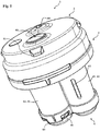
- FIG. 1 shows a schematic view of the vent valve (1) according to the invention for an SCR container, which has a housing (2), which consists of an upper part (3) and a lower part (4) connected thereto.
- the upper part (3) is non-positively and positively in the view shown with the Lower part (4) connected and ready for installation in an SCR container, with its outer wall, it is welded to produce a cohesive and fluid-tight connection.
- the upper part (3), as well as the lower part (4) were produced by injection molding of a HDPE.
- the upper part (3) has two outlet openings (60) which are designed as a pressure relief valve, as well as a vacuum valve and constitute a fluid connection to the environment (94).
- outlet openings (60) are designed as a pressure relief valve, as well as a vacuum valve and constitute a fluid connection to the environment (94).
- umbrella mushroom valves were used to close the outlet openings (60).
- the pressure relief valve has an opening pressure of about 10 mbar
- the vacuum valve has an opening pressure of about -20 mbar.
- the upper part (3) furthermore has a plurality of latching lugs (81), which are used to connect the upper part (3) to a cover device (not in FIG Fig. 1 shown) serve.
- the lower part (4) has two substantially hollow cylindrical valve housing, namely a first valve housing (42) and a second valve housing (45), wherein the first valve housing (42) has a first lateral surface (61) and the second valve housing (45) a second lateral surface (62).
- Both valve housings (42,45), or their interiors each have at least one communication opening (not in Fig. 1 but hidden by the securing device (80), which serve for fluid exchange with the operating fluid container interior.
- These communication ports are at the in FIG. 1 illustrated underside of the arranged two valve housing and correspond substantially to the end faces of the two hollow cylindrical valve housing designed.
- the lateral surface (61) of the first valve housing (42) is designed to be continuous and has no openings or openings.
- the lateral surface (62) of the second valve housing (45) has a slot-shaped further communication opening (63), via which the second valve housing (45), or its interior is fluidly connected to the interior of the operating fluid container.
- This third communication opening (63) has a size of about 19 mm 2 .
- FIG. 1 Furthermore, it can be seen a securing device (80), which is designed in the form of a cap made of a plastic, which is attached to the lower part (4) and a sliding out of the two in the valve housings (42,45) arranged valve body (not shown) prevented ,
- the cap (80) was produced by injection molding and is fastened to the lower part (4) via a plurality of latching noses (81) which are produced in one piece by injection molding with the lower part (4).
- FIG. 2 shows a schematic view of the injection-molded base (4) of the vent valve (1) according to the invention, wherein FIG. 2A facing the top and FIG. 2B with view towards the bottom of the lower part (4) is executed.
- baffles (71) are part of the Tropfenabscheiders (70) of the invention Serve bleed valve (1).
- first ventilation opening (51) and the second ventilation opening (52) can be seen, by means of which the later-formed receiving volume (31) and the first or second valve housing interior (43, 46) can be fluidly connected to one another.
- the two circular vents (51,52) are in the top of the in FIG. 2A shown lower parts (4), more precisely arranged in the partition wall (41).
- the clear width of the first ventilation opening (51) is greater than that of the second ventilation opening (52). More specifically, the inside width of the second vent (52) is about 1 mm, while the inside width of the first vent (51) is about 10 mm.
- the lower part (4) has a first and a second valve housing (42, 45), which in turn each have a lateral surface (61, 62). Only the lateral surface of the second valve housing (62) has a further communication opening (63), which is designed slot-shaped.
- the first valve housing (42) has a first communication opening (48) and the second valve housing (45) has a second communication opening (49) each having a fluid exchange between the first and second valve housing interior (43,46) and the not shown Allow operating fluid container interior (91).
- FIG. 2B represented view of the lower part (4), the two valve body (44,47) can be seen, the positionally variable in the two hollow cylindrical valve housings (42,45), and their interiors (43,46) are arranged.
- the first, as well as the second valve body (44,47) is made as a cup-shaped hollow body made of a plastic and has a total of six spacers (53) for centering the valve body in the valve housing interior (43,46), wherein in each case three of the six spacers ( 53) are arranged at an angular distance of 120 ° on the envelope of the valve body.
- FIG. 3 shows a schematic view of the injection-molded upper part (3) of the vent valve (1) according to the invention, wherein FIG. 3A facing the top and FIG. 3B is designed with a view towards the underside of the upper part (3).
- FIG. 3A again two of the plurality of detents (81), which were made in one piece with the upper part (3) and serve for non-positive and positive connection of the upper part (3) with the cover (82).
- FIG. 3B also shows the two outlet openings (60), as well as the screen mushroom valves arranged therein, which close these outlet openings (60) to provide a pressure relief valve, or a vacuum valve.
- baffles (71) are shown, which have a circular segment-like configuration and - as well as the Baffles (71) of the lower part (4) - serve as part of the Tropfenabscheiders (70) of the venting valve (1).
- the baffles (71) of the upper part (3) are also formed integrally with the upper part (3).
- FIG. 4 shows a further schematic view of the venting valve according to the invention (1) but this still has a plugged covering device (82).
- the covering device (82) designed as a cap consists of plastic and is securely connected to the latter via the latching lugs (81) of the upper part (3), but without preventing the fluid exchange with the environment (94).
- FIG. 5 shows a schematic view of a longitudinal section through the operating fluid container according to the invention (90), wherein the inventive vent valve (1), which is connected by welding material fit with the outer wall (93) of the wall (92) of the SCR container (90).
- the inventive vent valve (1) which is connected by welding material fit with the outer wall (93) of the wall (92) of the SCR container (90).
- the materials of the upper part (3), the lower part (4) and the outer wall (93) of the operating fluid container (90) together and enter into a material connection.
- the materials of the three aforementioned elements must be made of compatible plastics consist. In the present case these consist of HDPE. This advantageously ensures a particularly fluid-tight and at the same time the secure connection.
- the partition (41) which is formed integrally with the lower part (4) and in the connection of the upper part (3) and the lower part (4) limits a receiving volume (31), which for receiving from the escaping air Gas mixture contained operating fluid is suitable.
- the receiving volume (31) has a size of about 30 ml.
- this partition is plate-shaped, ie it has no steps or gradations, but has a substantially planar or planar configuration. Furthermore, the FIG. 5 it can be seen that the partition (41) over its entire extent a slight and substantially uniform curvature, which points away from the receiving volume (31).
- the two ventilation openings (51, 52) Arranged in the dividing wall (41) are also the two ventilation openings (51, 52) of the first and second valve housings (42, 45), which break through the dividing wall (41) and thus the receiving volume (31) with the first valve housing interior (43), or the second valve housing interior (46) fluidly connect.
- the two ventilation openings (51, 52) furthermore have valve seats (55), which are described below.
- valve bodies (44,47) which are designed as cup-shaped hollow bodies in the direction of the ventilation openings (51, 52). These cooperate with the valve seats (55) and safely and efficiently close the vent holes (51, 52) in the dividing wall (41) when the valve bodies (44, 47) are sufficiently raised by a rising working fluid level.
- first communication opening (48), or the second communication opening (49) On the end face of the first valve housing (42), or the second valve housing (45) is the first communication opening (48), or the second communication opening (49). A fluid exchange between the two valve housing interior spaces (43, 46) with the operating fluid container interior (91) is achieved via these two communication openings (48, 49).
- patch safety device (80) which prevents the two valve body (44,47) from sliding out of the valve housing interior (43,46).
- vent valve (1) according to the invention has a longitudinal extent (L), as well as with respect to this longitudinal extent (L) resulting housing height (h).
- the operating fluid When refueling the operating fluid container (90), the operating fluid enters the operating fluid container interior (91) and displaces as it rises the air therein, or the air-gas mixture therein.
- the thus displaced volume of the air or of the air-gas mixture initially enters the two valve housing internal spaces (43, 46) via the openings in the securing device (80) and the first and second communication openings (48, 49). It then flows within the two valve housing interior spaces (43, 46) past the two valve bodies (44, 47) and leaves the lower part (4) of the ventilation valve (1) via the two ventilation openings (51, 52) located in the partition wall (41). ,
- the displaced air-gas mixture After leaving the lower part (4), the displaced air-gas mixture enters the receiving volume (31) and is deflected several times by means of the labyrinth-like structures of the droplet separator (70) arranged therein, wherein the operating liquid contained in the air-gas mixture the impact surfaces (71) of the droplet separator (70) is deposited and runs down to this in the direction of the partition wall (41).
- the partition wall (41) As a result, leakage of operating fluid from the operating fluid container interior (91) into the environment (94) is effectively avoided in an advantageous manner.
- the volume of gas displaced from the working liquid container interior (91) after separation from the working liquid accumulates in the receiving volume (31) until the opening pressure of approximately 10 mbar of the pressure relief valve in one of the two outlet openings (60) is reached and the displaced one Gas volume is discharged into the environment (94).
- the pressure in the operating fluid container interior (91) decreases because operating fluid is removed. If the opening pressure of about -20 mbar is reached, then the vacuum valve in the other of the two outlet openings (60) open and air from the environment (94) flows for pressure equalization in the operating fluid container interior (91).
- the operating fluid separated as described above then passes through the first or second ventilation opening (51, 52) through the two valve housing interior spaces (43, 46) and the communication openings (51, 52) back into the operating fluid container interior (91). This is further facilitated by the fact that the dividing wall (41) is concavely curved towards the receiving volume (31) and thus the separated operating liquid can more easily reach the two ventilation openings (51, 52) arranged in the dividing wall (41).
- the first valve body (44) is first changed in its position and raised so that finally the seal (54) seals the valve seat (55) and thus the first ventilation opening (51). closes.
Landscapes
- Engineering & Computer Science (AREA)
- General Engineering & Computer Science (AREA)
- Mechanical Engineering (AREA)
- Self-Closing Valves And Venting Or Aerating Valves (AREA)
- Closures For Containers (AREA)
Claims (15)
- Vanne de désaération et/ou d'aération (1) destinée à un réservoir de liquide de service, laquelle présente les caractéristiques suivantes :- la vanne de désaération et/ou d'aération comporte un boîtier (2) pourvue d'une partie supérieure (3) et d'une partie inférieure (4) ;- la partie inférieure peut être reliée à la partie supérieure de telle sorte que le boîtier comporte un volume de réception (31) qui est délimité par une paroi de séparation (41) formée entre la partie supérieure et la partie inférieure ;- la partie inférieure comporte au moins un premier boîtier de vanne (42) pourvu d'un premier espace intérieur de boîtier de vanne (43) et un deuxième boîtier de vanne (45) pourvu d'un deuxième espace intérieur de boîtier de vanne (46), un premier corps de vanne (44) étant disposé dans le premier espace intérieur de boîtier de vanne et un deuxième corps de vanne (47) étant disposé de manière variable en position dans le deuxième espace intérieur de boîtier de vanne ;- le premier boîtier de vanne comporte une première ouverture de communication (48) destinée à l'échange de fluide entre l'espace intérieur du premier boîtier de vanne et un espace intérieur (91) du réservoir de liquide de service ;- le deuxième boîtier de vanne comporte une deuxième ouverture de communication (49) destinée à l'échange de fluide entre l'espace intérieur du deuxième boîtier de vanne et l'espace intérieur du réservoir de liquide de service ;- une première ouverture de ventilation (51), au moyen de laquelle le volume de réception et l'espace intérieur du premier boîtier de vanne peuvent être reliés fluidiquement, et une deuxième ouverture de ventilation (52), au moyen de laquelle le volume de réception et l'espace intérieur du deuxième boîtier de vanne peuvent être reliés fluidiquement, sont ménagées dans la paroi de séparation et- la première ouverture de ventilation et la deuxième ouverture de ventilation sont ménagées sensiblement à la même hauteur de boîtier (h) par rapport à l'extension longitudinale (L) du boîtier,caractérisée en ce que
la partie supérieure (3) comporte au moins une ouverture de sortie (60) qui traverse la paroi de la partie supérieure et forme une liaison fluidique allant du volume de réception (31) à l'environnement (94), et l'orifice de sortie (60) comprenant une vanne de surpression et/ou de dépression. - Vanne de désaération et/ou d'aération selon la revendication 1, caractérisée en ce que la partie supérieure comporte au moins deux ouvertures de sortie (60), une première ouverture de sortie (60) comportant une vanne de surpression et une deuxième ouverture de sortie (60) comportant une vanne de dépression et la paroi de séparation (41) étant formée par une paroi de la partie inférieure (4) .
- Vanne de désaération et/ou d'aération selon l'une au moins des revendications précédentes, caractérisée en ce que le diamètre intérieur de la première ouverture de ventilation est supérieur au diamètre intérieur de la deuxième ouverture de ventilation.
- Vanne de désaération et/ou d'aération selon l'une au moins des revendications précédentes, caractérisée en ce que le premier boîtier de vanne présente une surface latérale continue (61).
- Vanne de désaération et/ou d'aération selon l'une au moins des revendications précédentes, caractérisée en ce que le deuxième boîtier de vanne comporte au moins une troisième ouverture de communication (63) destinée à l'échange de fluide entre le deuxième espace intérieur de boîtier de vanne et l'espace intérieur du réservoir de liquide de service.
- Vanne de désaération et/ou d'aération selon l'une au moins des revendications précédentes, caractérisée en ce que la partie supérieure et la partie inférieure sont reliées entre elles par une liaison par complémentarité de formes et/ou par une liaison en force ou par une liaison de matière.
- Vanne de désaération et/ou d'aération selon la revendication 6, caractérisée en ce que la partie supérieure et la partie inférieure sont reliées par une liaison étanche aux fluides.
- Vanne de désaération et/ou d'aération selon la revendication 7, caractérisée en ce que la partie supérieure, la partie inférieure et le réservoir de liquide de service peuvent être reliés entre eux de manière étanche par une liaison de matière.
- Vanne de désaération et/ou d'aération selon l'une au moins des revendications précédentes, caractérisée en ce qu'un collecteur de gouttes (70) est disposé à l'intérieur du volume de réception.
- Vanne de désaération et/ou d'aération selon la revendication 9, caractérisée en ce que le collecteur de gouttes présente au moins une surface de déflexion (71) pourvue d'une structure en labyrinthe.
- Vanne de désaération et/ou d'aération selon l'une des revendications 9 ou 10, caractérisée en ce que le collecteur de gouttes est réalisé d'une seule pièce avec la partie supérieure et/ou la partie inférieure.
- Vanne de désaération et/ou d'aération selon au moins l'une des revendications précédentes, caractérisée en ce que la paroi de séparation est incurvée au moins par endroits en s'écartant du volume de réception.
- Vanne de désaération et/ou d'aération selon l'une au moins des revendications précédentes, comprenant en outre au moins un dispositif de fixation (80) destiné à fixer l'ensemble du premier corps de vanne dans le premier espace intérieur du boîtier de vanne et/ou du deuxième corps de vanne dans le deuxième espace intérieur du boîtier de vanne.
- Réservoir de liquide de service (90) comprenant une vanne de désaération et/ou d'aération selon l'une au moins des revendications précédentes.
- Réservoir de liquide de service selon la revendication 14, la vanne de désaération et/ou d'aération étant reliée de manière étanche aux fluides à la paroi extérieure (93) du réservoir de fluide de service.
Applications Claiming Priority (2)
| Application Number | Priority Date | Filing Date | Title |
|---|---|---|---|
| DE102016204770.1A DE102016204770A1 (de) | 2016-03-22 | 2016-03-22 | Ent- und/oder Belüftungsventil für einen Betriebsflüssigkeitsbehälter |
| PCT/EP2017/055189 WO2017162421A1 (fr) | 2016-03-22 | 2017-03-06 | Soupape de purge et/ou d'aération pour un réservoir de liquide de fonctionnement |
Publications (2)
| Publication Number | Publication Date |
|---|---|
| EP3433520A1 EP3433520A1 (fr) | 2019-01-30 |
| EP3433520B1 true EP3433520B1 (fr) | 2019-10-16 |
Family
ID=58231614
Family Applications (1)
| Application Number | Title | Priority Date | Filing Date |
|---|---|---|---|
| EP17709051.1A Active EP3433520B1 (fr) | 2016-03-22 | 2017-03-06 | Soupape de purge et/ou d'aération pour un réservoir de liquide de fonctionnement |
Country Status (3)
| Country | Link |
|---|---|
| EP (1) | EP3433520B1 (fr) |
| DE (1) | DE102016204770A1 (fr) |
| WO (1) | WO2017162421A1 (fr) |
Families Citing this family (3)
| Publication number | Priority date | Publication date | Assignee | Title |
|---|---|---|---|---|
| JP6886434B2 (ja) * | 2018-07-27 | 2021-06-16 | 株式会社ニフコ | 燃料タンク用弁装置 |
| US11324914B2 (en) * | 2018-11-01 | 2022-05-10 | Percussionaire Corporation | Percussive ventilation breathing head and accessories |
| USD1051376S1 (en) | 2019-04-23 | 2024-11-12 | Percussionaire Corporation | Ventilator coupler |
Family Cites Families (7)
| Publication number | Priority date | Publication date | Assignee | Title |
|---|---|---|---|---|
| JP3777214B2 (ja) * | 1996-01-08 | 2006-05-24 | 株式会社ニフコ | 燃料流出防止弁装置 |
| AU5445598A (en) * | 1996-11-20 | 1998-06-10 | Clean Diesel Technologies, Inc. | Selective catalytic no reduction utilizing urea without catalyst fouling |
| JP3911185B2 (ja) * | 2002-04-05 | 2007-05-09 | 株式会社ニフコ | 過給油防止バルブ |
| FR2896568B1 (fr) * | 2006-01-26 | 2008-03-14 | Inergy Automotive Systems Res | Dispositif pour circuit de mise a l'air d'un reservoir a liquide et clapet integrant ledit dispositif |
| DE102013013212A1 (de) * | 2013-08-09 | 2015-02-12 | Kautex Textron Gmbh & Co. Kg | Universelles Abschaltventil |
| KR102039656B1 (ko) * | 2014-03-05 | 2019-11-06 | 가부시키가이샤 파이오락꾸스 | 연료 탱크용 밸브 장치 |
| KR101655655B1 (ko) * | 2015-02-26 | 2016-09-07 | 현대자동차주식회사 | 차량의 요소수 탱크용 충전제한 통기밸브 |
-
2016
- 2016-03-22 DE DE102016204770.1A patent/DE102016204770A1/de not_active Withdrawn
-
2017
- 2017-03-06 EP EP17709051.1A patent/EP3433520B1/fr active Active
- 2017-03-06 WO PCT/EP2017/055189 patent/WO2017162421A1/fr not_active Ceased
Non-Patent Citations (1)
| Title |
|---|
| None * |
Also Published As
| Publication number | Publication date |
|---|---|
| WO2017162421A1 (fr) | 2017-09-28 |
| DE102016204770A1 (de) | 2017-09-28 |
| EP3433520A1 (fr) | 2019-01-30 |
Similar Documents
| Publication | Publication Date | Title |
|---|---|---|
| DE69907820T2 (de) | Behälter für kraftstofftank und kraftstofftank mit einem solchen behälter | |
| DE69919956T2 (de) | Zweistufiges Tankentlüftungsventil für ein Dampfverwertungssystem und Verfahren zu seiner Herstellung | |
| DE60008169T2 (de) | Anordnung für einen deckellosen Einfüllstutzen eines Kraftstofftanks | |
| DE102013013213B4 (de) | Betriebsflüssigkeitsbehälter mit integriertem Ent- und/oder Belüftungsventil | |
| DE10255659A1 (de) | Ausflussbegrenzungsvorrichtung eines Kraftstofftanks | |
| EP3149301B1 (fr) | Réservoir recevant une solution aqueuse d'urée dans un véhicule automobile | |
| DE19849820A1 (de) | Kraftstoff-Tanksystem für ein Kraftfahrzeug | |
| DE10021054A1 (de) | Kraftstoffpumpenmodul | |
| DE102008061264A1 (de) | Kraftstoffbehälter | |
| DE112013001029B4 (de) | Kraftstoffdüsen-Aufnahmeanordnung | |
| EP4212451A1 (fr) | Distributeur de gouttes | |
| EP3433520B1 (fr) | Soupape de purge et/ou d'aération pour un réservoir de liquide de fonctionnement | |
| DE2207210A1 (de) | Brennstoff-Einfüllkappe | |
| DE102006029672A1 (de) | Kraftstofftankventil | |
| WO2011032617A1 (fr) | Système de bouchon de fermeture pour accumulateur | |
| EP2400192A2 (fr) | Soupape d'aération | |
| DE4023094C2 (de) | Kunststoff-Kraftstoffbehälter für ein Kraftfahrzeug | |
| DE602004009648T2 (de) | Entlüftungsventil für Benzindämpfe und Befestigungsverfahren | |
| EP0568005B1 (fr) | Soupape de purge pour un réservoir | |
| DE60207022T2 (de) | Multifunktionseinheit in einem Kraftstoffsystem, Tank mit einer solchen Einheit und Verfahren zur Herstellung des Systems | |
| DE60222838T2 (de) | Leck hemmende Autobatterie | |
| DE4100388C2 (fr) | ||
| DE10110189B4 (de) | Kraftstoffbehälter | |
| DE60027304T2 (de) | Sicherheitsdichtung des schliesselements einer fülltüte für grossbehälter | |
| DE20120143U1 (de) | Sprühdose |
Legal Events
| Date | Code | Title | Description |
|---|---|---|---|
| STAA | Information on the status of an ep patent application or granted ep patent |
Free format text: STATUS: UNKNOWN |
|
| STAA | Information on the status of an ep patent application or granted ep patent |
Free format text: STATUS: THE INTERNATIONAL PUBLICATION HAS BEEN MADE |
|
| PUAI | Public reference made under article 153(3) epc to a published international application that has entered the european phase |
Free format text: ORIGINAL CODE: 0009012 |
|
| STAA | Information on the status of an ep patent application or granted ep patent |
Free format text: STATUS: REQUEST FOR EXAMINATION WAS MADE |
|
| 17P | Request for examination filed |
Effective date: 20181005 |
|
| AK | Designated contracting states |
Kind code of ref document: A1 Designated state(s): AL AT BE BG CH CY CZ DE DK EE ES FI FR GB GR HR HU IE IS IT LI LT LU LV MC MK MT NL NO PL PT RO RS SE SI SK SM TR |
|
| AX | Request for extension of the european patent |
Extension state: BA ME |
|
| GRAP | Despatch of communication of intention to grant a patent |
Free format text: ORIGINAL CODE: EPIDOSNIGR1 |
|
| STAA | Information on the status of an ep patent application or granted ep patent |
Free format text: STATUS: GRANT OF PATENT IS INTENDED |
|
| DAV | Request for validation of the european patent (deleted) | ||
| DAX | Request for extension of the european patent (deleted) | ||
| RIC1 | Information provided on ipc code assigned before grant |
Ipc: B60K 15/03 20060101ALI20190517BHEP Ipc: F16K 24/04 20060101AFI20190517BHEP Ipc: B60K 15/035 20060101ALI20190517BHEP Ipc: B60K 15/00 20060101ALI20190517BHEP |
|
| INTG | Intention to grant announced |
Effective date: 20190612 |
|
| GRAS | Grant fee paid |
Free format text: ORIGINAL CODE: EPIDOSNIGR3 |
|
| GRAA | (expected) grant |
Free format text: ORIGINAL CODE: 0009210 |
|
| STAA | Information on the status of an ep patent application or granted ep patent |
Free format text: STATUS: THE PATENT HAS BEEN GRANTED |
|
| AK | Designated contracting states |
Kind code of ref document: B1 Designated state(s): AL AT BE BG CH CY CZ DE DK EE ES FI FR GB GR HR HU IE IS IT LI LT LU LV MC MK MT NL NO PL PT RO RS SE SI SK SM TR |
|
| REG | Reference to a national code |
Ref country code: GB Ref legal event code: FG4D Free format text: NOT ENGLISH |
|
| REG | Reference to a national code |
Ref country code: CH Ref legal event code: EP |
|
| REG | Reference to a national code |
Ref country code: DE Ref legal event code: R096 Ref document number: 502017002602 Country of ref document: DE |
|
| REG | Reference to a national code |
Ref country code: IE Ref legal event code: FG4D Free format text: LANGUAGE OF EP DOCUMENT: GERMAN |
|
| REG | Reference to a national code |
Ref country code: AT Ref legal event code: REF Ref document number: 1191604 Country of ref document: AT Kind code of ref document: T Effective date: 20191115 |
|
| REG | Reference to a national code |
Ref country code: NL Ref legal event code: MP Effective date: 20191016 |
|
| REG | Reference to a national code |
Ref country code: LT Ref legal event code: MG4D |
|
| PG25 | Lapsed in a contracting state [announced via postgrant information from national office to epo] |
Ref country code: FI Free format text: LAPSE BECAUSE OF FAILURE TO SUBMIT A TRANSLATION OF THE DESCRIPTION OR TO PAY THE FEE WITHIN THE PRESCRIBED TIME-LIMIT Effective date: 20191016 Ref country code: PT Free format text: LAPSE BECAUSE OF FAILURE TO SUBMIT A TRANSLATION OF THE DESCRIPTION OR TO PAY THE FEE WITHIN THE PRESCRIBED TIME-LIMIT Effective date: 20200217 Ref country code: BG Free format text: LAPSE BECAUSE OF FAILURE TO SUBMIT A TRANSLATION OF THE DESCRIPTION OR TO PAY THE FEE WITHIN THE PRESCRIBED TIME-LIMIT Effective date: 20200116 Ref country code: GR Free format text: LAPSE BECAUSE OF FAILURE TO SUBMIT A TRANSLATION OF THE DESCRIPTION OR TO PAY THE FEE WITHIN THE PRESCRIBED TIME-LIMIT Effective date: 20200117 Ref country code: LV Free format text: LAPSE BECAUSE OF FAILURE TO SUBMIT A TRANSLATION OF THE DESCRIPTION OR TO PAY THE FEE WITHIN THE PRESCRIBED TIME-LIMIT Effective date: 20191016 Ref country code: NO Free format text: LAPSE BECAUSE OF FAILURE TO SUBMIT A TRANSLATION OF THE DESCRIPTION OR TO PAY THE FEE WITHIN THE PRESCRIBED TIME-LIMIT Effective date: 20200116 Ref country code: NL Free format text: LAPSE BECAUSE OF FAILURE TO SUBMIT A TRANSLATION OF THE DESCRIPTION OR TO PAY THE FEE WITHIN THE PRESCRIBED TIME-LIMIT Effective date: 20191016 Ref country code: SE Free format text: LAPSE BECAUSE OF FAILURE TO SUBMIT A TRANSLATION OF THE DESCRIPTION OR TO PAY THE FEE WITHIN THE PRESCRIBED TIME-LIMIT Effective date: 20191016 Ref country code: PL Free format text: LAPSE BECAUSE OF FAILURE TO SUBMIT A TRANSLATION OF THE DESCRIPTION OR TO PAY THE FEE WITHIN THE PRESCRIBED TIME-LIMIT Effective date: 20191016 Ref country code: LT Free format text: LAPSE BECAUSE OF FAILURE TO SUBMIT A TRANSLATION OF THE DESCRIPTION OR TO PAY THE FEE WITHIN THE PRESCRIBED TIME-LIMIT Effective date: 20191016 |
|
| PG25 | Lapsed in a contracting state [announced via postgrant information from national office to epo] |
Ref country code: IS Free format text: LAPSE BECAUSE OF FAILURE TO SUBMIT A TRANSLATION OF THE DESCRIPTION OR TO PAY THE FEE WITHIN THE PRESCRIBED TIME-LIMIT Effective date: 20200224 Ref country code: RS Free format text: LAPSE BECAUSE OF FAILURE TO SUBMIT A TRANSLATION OF THE DESCRIPTION OR TO PAY THE FEE WITHIN THE PRESCRIBED TIME-LIMIT Effective date: 20191016 Ref country code: HR Free format text: LAPSE BECAUSE OF FAILURE TO SUBMIT A TRANSLATION OF THE DESCRIPTION OR TO PAY THE FEE WITHIN THE PRESCRIBED TIME-LIMIT Effective date: 20191016 |
|
| PG25 | Lapsed in a contracting state [announced via postgrant information from national office to epo] |
Ref country code: AL Free format text: LAPSE BECAUSE OF FAILURE TO SUBMIT A TRANSLATION OF THE DESCRIPTION OR TO PAY THE FEE WITHIN THE PRESCRIBED TIME-LIMIT Effective date: 20191016 |
|
| REG | Reference to a national code |
Ref country code: DE Ref legal event code: R097 Ref document number: 502017002602 Country of ref document: DE |
|
| PG2D | Information on lapse in contracting state deleted |
Ref country code: IS |
|
| PG25 | Lapsed in a contracting state [announced via postgrant information from national office to epo] |
Ref country code: EE Free format text: LAPSE BECAUSE OF FAILURE TO SUBMIT A TRANSLATION OF THE DESCRIPTION OR TO PAY THE FEE WITHIN THE PRESCRIBED TIME-LIMIT Effective date: 20191016 Ref country code: DK Free format text: LAPSE BECAUSE OF FAILURE TO SUBMIT A TRANSLATION OF THE DESCRIPTION OR TO PAY THE FEE WITHIN THE PRESCRIBED TIME-LIMIT Effective date: 20191016 Ref country code: CZ Free format text: LAPSE BECAUSE OF FAILURE TO SUBMIT A TRANSLATION OF THE DESCRIPTION OR TO PAY THE FEE WITHIN THE PRESCRIBED TIME-LIMIT Effective date: 20191016 Ref country code: RO Free format text: LAPSE BECAUSE OF FAILURE TO SUBMIT A TRANSLATION OF THE DESCRIPTION OR TO PAY THE FEE WITHIN THE PRESCRIBED TIME-LIMIT Effective date: 20191016 Ref country code: ES Free format text: LAPSE BECAUSE OF FAILURE TO SUBMIT A TRANSLATION OF THE DESCRIPTION OR TO PAY THE FEE WITHIN THE PRESCRIBED TIME-LIMIT Effective date: 20191016 Ref country code: IS Free format text: LAPSE BECAUSE OF FAILURE TO SUBMIT A TRANSLATION OF THE DESCRIPTION OR TO PAY THE FEE WITHIN THE PRESCRIBED TIME-LIMIT Effective date: 20200216 |
|
| PLBE | No opposition filed within time limit |
Free format text: ORIGINAL CODE: 0009261 |
|
| STAA | Information on the status of an ep patent application or granted ep patent |
Free format text: STATUS: NO OPPOSITION FILED WITHIN TIME LIMIT |
|
| PG25 | Lapsed in a contracting state [announced via postgrant information from national office to epo] |
Ref country code: SM Free format text: LAPSE BECAUSE OF FAILURE TO SUBMIT A TRANSLATION OF THE DESCRIPTION OR TO PAY THE FEE WITHIN THE PRESCRIBED TIME-LIMIT Effective date: 20191016 Ref country code: IT Free format text: LAPSE BECAUSE OF FAILURE TO SUBMIT A TRANSLATION OF THE DESCRIPTION OR TO PAY THE FEE WITHIN THE PRESCRIBED TIME-LIMIT Effective date: 20191016 Ref country code: SK Free format text: LAPSE BECAUSE OF FAILURE TO SUBMIT A TRANSLATION OF THE DESCRIPTION OR TO PAY THE FEE WITHIN THE PRESCRIBED TIME-LIMIT Effective date: 20191016 |
|
| 26N | No opposition filed |
Effective date: 20200717 |
|
| PG25 | Lapsed in a contracting state [announced via postgrant information from national office to epo] |
Ref country code: MC Free format text: LAPSE BECAUSE OF FAILURE TO SUBMIT A TRANSLATION OF THE DESCRIPTION OR TO PAY THE FEE WITHIN THE PRESCRIBED TIME-LIMIT Effective date: 20191016 |
|
| REG | Reference to a national code |
Ref country code: CH Ref legal event code: PL |
|
| PG25 | Lapsed in a contracting state [announced via postgrant information from national office to epo] |
Ref country code: SI Free format text: LAPSE BECAUSE OF FAILURE TO SUBMIT A TRANSLATION OF THE DESCRIPTION OR TO PAY THE FEE WITHIN THE PRESCRIBED TIME-LIMIT Effective date: 20191016 |
|
| REG | Reference to a national code |
Ref country code: BE Ref legal event code: MM Effective date: 20200331 |
|
| PG25 | Lapsed in a contracting state [announced via postgrant information from national office to epo] |
Ref country code: LU Free format text: LAPSE BECAUSE OF NON-PAYMENT OF DUE FEES Effective date: 20200306 |
|
| PG25 | Lapsed in a contracting state [announced via postgrant information from national office to epo] |
Ref country code: LI Free format text: LAPSE BECAUSE OF NON-PAYMENT OF DUE FEES Effective date: 20200331 Ref country code: IE Free format text: LAPSE BECAUSE OF NON-PAYMENT OF DUE FEES Effective date: 20200306 Ref country code: CH Free format text: LAPSE BECAUSE OF NON-PAYMENT OF DUE FEES Effective date: 20200331 |
|
| PG25 | Lapsed in a contracting state [announced via postgrant information from national office to epo] |
Ref country code: BE Free format text: LAPSE BECAUSE OF NON-PAYMENT OF DUE FEES Effective date: 20200331 |
|
| PG25 | Lapsed in a contracting state [announced via postgrant information from national office to epo] |
Ref country code: TR Free format text: LAPSE BECAUSE OF FAILURE TO SUBMIT A TRANSLATION OF THE DESCRIPTION OR TO PAY THE FEE WITHIN THE PRESCRIBED TIME-LIMIT Effective date: 20191016 Ref country code: MT Free format text: LAPSE BECAUSE OF FAILURE TO SUBMIT A TRANSLATION OF THE DESCRIPTION OR TO PAY THE FEE WITHIN THE PRESCRIBED TIME-LIMIT Effective date: 20191016 Ref country code: CY Free format text: LAPSE BECAUSE OF FAILURE TO SUBMIT A TRANSLATION OF THE DESCRIPTION OR TO PAY THE FEE WITHIN THE PRESCRIBED TIME-LIMIT Effective date: 20191016 |
|
| PG25 | Lapsed in a contracting state [announced via postgrant information from national office to epo] |
Ref country code: MK Free format text: LAPSE BECAUSE OF FAILURE TO SUBMIT A TRANSLATION OF THE DESCRIPTION OR TO PAY THE FEE WITHIN THE PRESCRIBED TIME-LIMIT Effective date: 20191016 |
|
| REG | Reference to a national code |
Ref country code: AT Ref legal event code: MM01 Ref document number: 1191604 Country of ref document: AT Kind code of ref document: T Effective date: 20220306 |
|
| P01 | Opt-out of the competence of the unified patent court (upc) registered |
Effective date: 20230526 |
|
| PG25 | Lapsed in a contracting state [announced via postgrant information from national office to epo] |
Ref country code: AT Free format text: LAPSE BECAUSE OF NON-PAYMENT OF DUE FEES Effective date: 20220306 |
|
| PGFP | Annual fee paid to national office [announced via postgrant information from national office to epo] |
Ref country code: GB Payment date: 20260324 Year of fee payment: 10 |
|
| PGFP | Annual fee paid to national office [announced via postgrant information from national office to epo] |
Ref country code: DE Payment date: 20260303 Year of fee payment: 10 |
|
| PGFP | Annual fee paid to national office [announced via postgrant information from national office to epo] |
Ref country code: FR Payment date: 20260320 Year of fee payment: 10 |