EP3433574B1 - Dispositif pour mesurer un objet en 3 dimensions, procédé et programme informatique associés à déclenchement basé sur une image - Google Patents
Dispositif pour mesurer un objet en 3 dimensions, procédé et programme informatique associés à déclenchement basé sur une image Download PDFInfo
- Publication number
- EP3433574B1 EP3433574B1 EP17712986.3A EP17712986A EP3433574B1 EP 3433574 B1 EP3433574 B1 EP 3433574B1 EP 17712986 A EP17712986 A EP 17712986A EP 3433574 B1 EP3433574 B1 EP 3433574B1
- Authority
- EP
- European Patent Office
- Prior art keywords
- image information
- image
- evaluation
- trigger
- measurement
- Prior art date
- Legal status (The legal status is an assumption and is not a legal conclusion. Google has not performed a legal analysis and makes no representation as to the accuracy of the status listed.)
- Active
Links
Images



Classifications
-
- G—PHYSICS
- G01—MEASURING; TESTING
- G01B—MEASURING LENGTH, THICKNESS OR SIMILAR LINEAR DIMENSIONS; MEASURING ANGLES; MEASURING AREAS; MEASURING IRREGULARITIES OF SURFACES OR CONTOURS
- G01B11/00—Measuring arrangements characterised by the use of optical techniques
- G01B11/24—Measuring arrangements characterised by the use of optical techniques for measuring contours or curvatures
- G01B11/25—Measuring arrangements characterised by the use of optical techniques for measuring contours or curvatures by projecting a pattern, e.g. one or more lines, moiré fringes on the object
- G01B11/2518—Projection by scanning of the object
-
- G—PHYSICS
- G01—MEASURING; TESTING
- G01B—MEASURING LENGTH, THICKNESS OR SIMILAR LINEAR DIMENSIONS; MEASURING ANGLES; MEASURING AREAS; MEASURING IRREGULARITIES OF SURFACES OR CONTOURS
- G01B11/00—Measuring arrangements characterised by the use of optical techniques
- G01B11/24—Measuring arrangements characterised by the use of optical techniques for measuring contours or curvatures
- G01B11/245—Measuring arrangements characterised by the use of optical techniques for measuring contours or curvatures using a plurality of fixed, simultaneously operating transducers
-
- G—PHYSICS
- G01—MEASURING; TESTING
- G01S—RADIO DIRECTION-FINDING; RADIO NAVIGATION; DETERMINING DISTANCE OR VELOCITY BY USE OF RADIO WAVES; LOCATING OR PRESENCE-DETECTING BY USE OF THE REFLECTION OR RERADIATION OF RADIO WAVES; ANALOGOUS ARRANGEMENTS USING OTHER WAVES
- G01S17/00—Systems using the reflection or reradiation of electromagnetic waves other than radio waves, e.g. lidar systems
- G01S17/02—Systems using the reflection of electromagnetic waves other than radio waves
- G01S17/06—Systems determining position data of a target
- G01S17/46—Indirect determination of position data
- G01S17/48—Active triangulation systems, i.e. using the transmission and reflection of electromagnetic waves other than radio waves
-
- G—PHYSICS
- G06—COMPUTING OR CALCULATING; COUNTING
- G06T—IMAGE DATA PROCESSING OR GENERATION, IN GENERAL
- G06T7/00—Image analysis
- G06T7/50—Depth or shape recovery
- G06T7/521—Depth or shape recovery from laser ranging, e.g. using interferometry; from the projection of structured light
-
- G—PHYSICS
- G06—COMPUTING OR CALCULATING; COUNTING
- G06T—IMAGE DATA PROCESSING OR GENERATION, IN GENERAL
- G06T7/00—Image analysis
- G06T7/50—Depth or shape recovery
- G06T7/55—Depth or shape recovery from multiple images
- G06T7/579—Depth or shape recovery from multiple images from motion
-
- H—ELECTRICITY
- H04—ELECTRIC COMMUNICATION TECHNIQUE
- H04N—PICTORIAL COMMUNICATION, e.g. TELEVISION
- H04N13/00—Stereoscopic video systems; Multi-view video systems; Details thereof
- H04N13/20—Image signal generators
- H04N13/204—Image signal generators using stereoscopic image cameras
- H04N13/207—Image signal generators using stereoscopic image cameras using a single two-dimensional [2D] image sensor
- H04N13/221—Image signal generators using stereoscopic image cameras using a single two-dimensional [2D] image sensor using the relative movement between cameras and objects
Definitions
- Embodiments according to the present invention relate to a device for 3-dimensional measurement of an object.
- a 3-dimensional image of an object can be obtained, for example, by laser light section scanning (also called laser light section scanning).
- the sensor head consists, for example, of one or more laser line generators and one or more measuring cameras, which for example, are arranged in a defined geometric relationship to one another.
- the sensor head made up of the laser line generator(s) and the measuring camera(s) are also arranged in a defined geometric relationship to a measurement object (which changes in a previously defined manner, for example, during a measurement).
- a continuous or triggered operation of a profile measurement is carried out by a sensor head made up of the laser line generator and the measuring camera.
- the measuring object there is also a fixed assignment between the measuring object and the laser line. This results, for example, from a geometric structure or from a connection between the scanner's propulsion unit, laser line generator(s) and measuring camera(s). Typically, there is also a (for example predetermined) direction of movement.
- an incremental encoder can be used to trigger the measuring camera(s). This means that measured values are recorded when there is an external trigger.
- the triggering can be carried out, for example, by a controlled or detected drive on a movement system of the measuring setup.
- a direction of movement typically there is a (e.g. predetermined) direction of movement.
- a constant scanning speed can be used.
- time-controlled triggering can be used.
- a free-running scanner can also be used in this case.
- the US 2014/0285658 A1 describes a non-contact measurement device.
- the measurement device includes one or more imaging devices that capture image data of a surface of an object.
- the device includes one or more projection pattern generators that generate divergent patterns on a surface of the object within a field of view of the imaging device.
- a computer system uses image data captured by the imaging device(s), a computer system determines a set of attributes of the surface of the object and/or automatically determines whether the measurement object is within a measurement region.
- the EP 0 228 500 A2 describes a method and an associated device for contactless measurement of the wheel profile of the wheels of railway wheel sets, in which the profile is at least partially illuminated. It is proposed that each wheel is moved along a measuring path and, at least in a predefined measuring position, is illuminated at least approximately radially by at least one lighting device that creates a light section or a light edge on the circumferential surface of the wheel during the movement along the measuring path, wherein the profile image resulting from the illumination is captured by at least one camera and sent to an evaluation device for evaluation.
- an auxiliary rail connected or connectable to a track, is provided in a measuring section for each wheel of a wheelset, that the lighting device has optical means for generating a light section or a light edge on the peripheral surface of the wheel and is arranged below a plane of movement of the associated auxiliary rail, that the lighting device is assigned at least one camera for detecting the profile of the light section or the light edge, wherein the camera is connected to an evaluation device and this is connected to an output unit, and wherein the device has means for detecting at least the measuring position which triggers the activation of the device.
- the US 2008/0204763 A1 describes a measuring apparatus and method for area inspection.
- An imaging apparatus and method for measuring three-dimensional characteristics of an object using area data acquisition and analysis comprises a device for configuring the area data acquisition and analysis before starting the measurement.
- the apparatus further comprises a device for generating an image of the object by detecting reflected light from the object using at least one sensor having pixels.
- the apparatus further comprises a device for obtaining area data of the object measured in sensor pixel units.
- the apparatus further comprises means for calibrating the obtained range data from sensor pixel values to world coordinates.
- the apparatus further comprises means for correcting the calibrated range data by re-sampling the range data to a uniform grid.
- the apparatus further comprises means for analyzing the calibrated and corrected range data to obtain the three-dimensional characteristics of the object.
- the EP 3 163 252 A1 describes a device for three-dimensional shape determination, a measuring system for three-dimensional shape determination, and corresponding methods and computer programs.
- a device for three-dimensional shape determination comprises a mark search unit which calculates a coordinate of a part of a surface of a measurement object which comprises an optical cutting line using a search mark.
- the US 2014/240464 A1 describes a context-based depth sensor control.
- An electronic device includes a depth sensor, a first imaging camera, and a controller.
- the depth sensor includes a modulated light projector to project a modulated light pattern.
- the first imaging camera captures at least one reflection of the modulated light pattern.
- the controller selectively modifies at least the frequency or intensity or duration of projections of the modulated light pattern in response to at least one trigger event.
- the trigger event may be, for example, a change in ambient light, a detection of movement of the device, or a detection that the device is in a different environment.
- Embodiments according to the present invention provide a device for 3-dimensional measurement of an object.
- the device comprises an evaluation device for determining measurement results and a trigger device (also referred to as a trigger device) which is designed to receive image information from a measuring camera and to trigger a measurement output (for example, forwarding the image information to an evaluation device for determining measurement results) or a (further, more detailed) evaluation of the image information by an evaluation device for determining measurement results, depending on an image content of the image information.
- a trigger device also referred to as a trigger device
- the trigger device is designed to carry out a comparison of one or more current image sensor analog signals with one or more reference image sensor analog signals stored in an analog memory in order to detect a temporal change in image information, wherein the analog comparison corresponds to the formation of difference images and enables detection of a movement of the image content in order to trigger the output of a digitized version of the image information via a digital interface of the image sensor based thereon.
- the triggering device is designed to analyse different features in different areas of the image content, whereby when evaluating features in different areas of the image content, objectively different image contents are considered at the same time, whereby the triggering device is designed to decide in which image contents relevant features are present in order to trigger the output of a digitalised version of the image information
- This embodiment according to the present invention is based on the knowledge that flexibility in a 3-dimensional measurement can be significantly increased if a measurement output or an evaluation of the image information by the evaluation device for determining measurement results is not carried out via mechanical position sensors, but via an evaluation of image information from a measuring camera.
- the image information provided by the measuring camera can be used not only for the determination of measurement results by the evaluation device, but also for determining a point in time when (or based on which image information) a measurement result is to be determined.
- a measurement output triggered based on the image content of the image information e.g.
- the measuring camera usually provides very high-resolution image information anyway, so that the measurement output or the evaluation of the image information can be triggered with essentially the same accuracy with which the image information itself is provided.
- the measurement output is triggered exclusively based on the image content. Accordingly, no further mechanical or other position sensors are required to trigger the measurement output or the evaluation of the image information.
- the triggering device is designed to carry out an image analysis and to trigger the measurement output or the evaluation of the image information depending on the image analysis.
- features are preferably identified in the image information that are considered to be criteria for triggering. For example, intersection points of a laser line with other lines of a predetermined or known position can be identified, and a position or location of the projected line (laser line) can be determined based on this.
- other features can also be recognized in the image analysis, such as movement or certain surface properties of an object to be measured or of a support component that supports the object to be measured.
- an evaluation by means of an image analysis leads to more precise results in many cases and in some cases also makes handling the device for 3-dimensional measurement of an object much easier than with conventional devices.
- the triggering device is designed to carry out an analog preprocessing of image sensor analog signals (for example without quantization with more than two levels) and, based on the analog preprocessing of the image sensor analog signals (or based on a result of the analog preprocessing and a corresponding decision as to whether a triggering condition is met), to forward the image information (for example a digitized version of the image information) via a digital interface of the image sensor or to (further, more detailed) evaluate the image information by an evaluation device for Determination of measurement results.
- analog preprocessing of the image sensor analog signals preferably close to the sensor, can typically be implemented very quickly and with low power consumption.
- a complex transmission of an entire image content can be avoided, for example, by preprocessing image sensor analog signals, preferably close to the sensor. This means that the forwarding of the image information or the further, more detailed evaluation of the image information to determine measurement results can be triggered with very short response times.
- a constant, bitrate-intensive output of digitized image information can be saved if the triggering is based on analog preprocessing of image sensor analog signals (and a decision as to whether a triggering condition exists). Overall, a very short response time can thus be achieved when triggering, and on the other hand, the (image) processing power required for this can be kept low.
- the triggering device is designed to trigger a digitization of image sensor analog signals and an output of a digitized version of the image information via a digital interface of the image sensor.
- the corresponding design avoids, for example, permanently or continuously digitized image information being output, even if it is not needed at all (because there is no triggering event). This saves transmission capacity and also energy.
- the triggering device is designed to compare image sensor analog signals with a threshold value and, based on a result of the comparison, to trigger the output of a digitized version of the image information via a digital interface of the image sensor.
- the triggering device is designed to compare a current image sensor analog signal with an image sensor analog signal stored in an analog memory in order to detect a temporal change in image information and, based thereon, to trigger the output of a digitized version of the image information via a digital interface of the image sensor.
- the triggering device is designed to carry out a combining analog processing of a plurality of image sensor analog signals and, based on a result of the combining analog processing, to trigger the output of a digitized version of the image information via a digital interface of the image sensor.
- a combining analog processing of a plurality of image sensor analog signals and, based on a result of the combining analog processing, to trigger the output of a digitized version of the image information via a digital interface of the image sensor.
- a comparison of one or more current image sensor analog signals with one or more values stored in an analog memory can, for example, enable detection of a movement in the image content. If, for example, such an analog comparison, which corresponds to the formation of difference images, detects that there is sufficient movement (or a movement of a predetermined size), an output of the digitized version of the image information can be triggered via the digital interface of the image sensor.
- a movement can be detected by an analog comparison of image sensor signals with image sensor analog signals (or corresponding signal values) stored in an analog memory, and the triggering can take place based on this analog and therefore fast motion detection.
- a combined analog processing of a plurality of image sensor analog signals can, for example, comprise a weighted or non-weighted addition or subtraction of image sensor analog signals from neighboring pixels.
- an analog combination of a plurality of image sensor analog signals can be used to perform spatial and/or temporal filtering, which, for example, in conjunction with a threshold value comparison of the combined signal (which is created by a combined analog processing of a plurality of image sensor analog signals) enables the presence of a specific structure in the image information to be detected, whereby the detection of a corresponding structure (e.g. a particularly bright point of a specific size, or a straight line, or another marking) can lead to the triggering of the output of the digitized version of the image information.
- a corresponding structure e.g. a particularly bright point of a specific size, or a straight line, or another marking
- the triggering device is designed to analyze image information showing a laser light section or another light section (for example by analog processing of the image sensor analog signals) and to trigger the forwarding of the image information or the evaluation of the image information by the evaluation device to determine measurement results based on the analysis. It has been shown that the analysis of image information showing a laser light section or another light section can be used in a very efficient and precise manner for triggering, since, for example, important features relevant to triggering can be located along the laser light section.
- the triggering device is designed to recognize 3-dimensional marks on a surface (for example on a surface of a base on which a measurement object is located) or two-dimensional optical properties along a laser line (for example a line written by a laser on a flat or curved surface) as features using a laser light section or another light section (for example by analog processing of the image sensor output signals) and, depending on the features recognized, to trigger the forwarding of the image information or the evaluation of the image information by the evaluation device to determine measurement results. It was thus recognized that 3-dimensional marks on the surface can be seen particularly well and with high precision using a laser light section or another light section.
- intersection points of the laser light section (or the other light section) with the 3-dimensional features on the surface are usually quite clearly visible and can therefore be easily evaluated for triggering.
- the presence of 3-dimensional marks or the presence of (typically spatially variable) two-dimensional optical properties along the laser line is a good criterion for triggering, since the presence of 3-dimensional marks on the surface or the presence of special two-dimensional optical properties along a laser light section (i.e. along a well-defined line) typically provides clear information about whether triggering should occur or not.
- triggering it is desirable for triggering to occur when the laser light section reaches a certain 3-dimensional mark on the surface or when the laser light section reaches an area in which certain two-dimensional optical properties along the laser line are detectable.
- the triggering of image information generated by a laser light section offers a high level of accuracy, since in this way a specific surface property along the laser light section, which is also important for further processing, is taken into account. This means that tolerances in the generation of the laser light section can also be compensated, for example, since the triggering occurs exactly when the laser light section hits an area with certain marks or certain optical properties.
- the triggering device is designed to receive information about a reliability of line detection or information about a width of a line, and to trigger the forwarding of the image information or the evaluation of the image information by the evaluation device to determine measurement results depending on this.
- a triggering occurs when a line generated by the laser light section is also clearly recognizable, which can be recognized, for example, by evaluating a reliability measure of line detection or by detecting a sufficiently small width of a line (e.g. in image information provided by the measuring camera).
- the triggering device is designed to detect when the image content (e.g. the image content provided by the measuring camera) has shifted by at least a predetermined shift (or by more than a predetermined shift) compared to a reference image content, and to trigger the forwarding of the image information or the evaluation of the image information by the evaluation device to determine measurement results depending on the detection of a shift.
- the image content e.g. the image content provided by the measuring camera
- the evaluation device e.g. the image content provided by the measuring camera
- the triggering device is designed to detect when the image content (e.g. the image content provided by the measuring camera) has shifted by at least a predetermined shift (or by more than a predetermined shift) compared to a reference image content, and to trigger the forwarding of the image information or the evaluation of the image information by the evaluation device to determine measurement results depending on the detection of a shift.
- Such a procedure can be advantageous if measurement results are to be generated at a certain spatial distance, for example.
- a shift for example by
- the triggering device is designed to trigger, based on the image content, a movement of a camera that generates the image information and/or a displacement of a light source (eg a laser line generator) that generates the Measurement object irradiated (e.g. relative to the object to be measured) and/or a movement of the measurement object, to determine or estimate.
- a light source eg a laser line generator
- the triggering device is designed to trigger the forwarding of the image information or the evaluation of the image information by the evaluation device to determine measurement results depending on the determination or estimation of the displacement.
- This embodiment is based on the knowledge that, based on image processing, a relative movement between a light source that irradiates the measurement object and/or a measuring camera and the object to be measured can be determined in various ways. In order to generate a reliable measurement result, it is therefore useful in some cases to evaluate such information about the displacement and, if a desired displacement is present (e.g. in relation to a previous determination of a measurement result), to trigger a new determination of a measurement result. In this way, a determination of measurement results with a certain spatial distance can be achieved.
- the triggering device is designed to utilize a 3-dimensional reconstruction for motion estimation when analyzing the image content, and/or to perform a comparison of gray value features in a feed direction, and/or to detect marks, and/or to detect color expressions.
- an image content which typically evaluates a grayscale image or a color image provided by the measuring camera
- a 3-dimensional reconstruction for example of an object or a substrate to be recorded
- the 3-dimensional reconstruction for motion estimation can, for example - unlike precise measurement - be based on "flat" camera images (representing an area extended in two dimensions) and may have a lower accuracy with regard to the resolution of surface contours than, for example, a laser light section. Nevertheless, the 3-dimensional reconstruction can have sufficient accuracy to trigger an evaluation of a laser light section.
- motion detection can be carried out based on a flat image (which does not just show a shot along a laser light section). Accordingly, motion detection can also be carried out by such a comparison of grayscale features in a feed direction (which can be specified, for example, by the carrier component or a movement of the carrier component). This motion detection can in turn be sufficient to recognize that the object to be measured has moved a certain distance, which in turn is a good criterion for triggering a measurement output or a further detailed evaluation of the image information.
- a detection of marks and/or colored expressions in a flat image can, for example, provide information about whether the object to be measured has moved to an extent that makes it appropriate to trigger a measurement output or a further, more detailed evaluation of the image information (or a laser light section).
- the triggering device is designed to evaluate height information or surface information (for example with regard to cracks and/or gaps and/or scratches) when analyzing the image content. It has been recognized that an evaluation of height information or surface information (for example in a flat image) can also provide information about whether a measurement output should be made or whether a further evaluation, for example of a laser light section, should be made.
- the triggering device can be designed to take into account image information that is recorded from different directions. In this way, for example, very meaningful information can be used for triggering. Image information that is recorded from several different directions, for example, enables particularly precise motion estimation, whereby a motion estimation can be used very well for triggering.
- the triggering device is designed to determine one or more polarization properties, or a change in one or more polarization properties (for example, to detect different materials detect, and/or to detect a variation in the penetration depth of a laser beam and/or to detect a relative movement between a camera and the measurement object and/or to detect a relative movement between a light source and the measurement object) and, depending on this, to trigger the forwarding of the image information or the evaluation of the image information by the evaluation device to determine measurement results.
- Triggering information can also be derived efficiently from polarization information or, in particular, from a change in the polarization information. Again, a change in the polarization information or polarization properties can be an indication that the object to be measured has moved so much that a new triggering is advisable.
- the triggering device is designed to decide whether a result (for example image information or a measurement result) is output or whether the output is suppressed. Suppressing an output can be useful, for example, to keep a data rate low and to avoid transmission of useless or redundant information.
- the triggering device is designed to analyze various features of the image content.
- the triggering device is designed to analyze features in different areas of the image content.
- the triggering device can, for example, make the decision as to whether a trigger should be made based on a combination of several features, thereby increasing the reliability of the decision. For example, information describing the presence of various features can be combined in a weighted manner to arrive at a decision.
- a decision is also made as to which image contents contain relevant or reliable features. In this way, when taking a flat image or image section into account, an even more reliable decision about triggering can be made than when viewing features only along a laser line.
- the triggering device is designed to generate one or more control signals for one or more laser line generators and/or to generate one or more control signals for one or more lighting devices in order to change the lighting of the measurement object depending on the image content of the image information.
- This exemplary embodiment is based on the knowledge that, for example, the laser line generator or another lighting device can be controlled in order to bring a projected line to a desired position. If, for example, it is recognized that a projected line is not yet in a desired position, the laser line generator or another lighting device can be controlled accordingly.
- the image information can also be used to recognize that, for example, a projected laser line is too dark or has poor contrast or is too bright. Accordingly, the generation of a projected laser line can be adapted to the requirements by controlling the laser line generator or by controlling another lighting device, for example both with regard to the position of the projected line and with regard to other properties, such as the brightness of the projected line.
- the triggering device is designed to recognize, based on the image content of the image information, whether a region of interest of the measurement object can be measured (for example with a desired accuracy) or not, and to trigger the forwarding of the image information or the evaluation of the image information by the evaluation device to determine measurement results depending on this. Accordingly, forwarding of the image information or the evaluation can only be carried out if the image content shows that a region of interest of the measurement object can be measured and is not shadowed, for example. Unnecessary data transmission (image transmission) or evaluation can thus be avoided, which saves resources.
- the device is designed to scan a measurement object in 3-dimensions without a camera for generating the image information and/or a light source for irradiating the measurement object being fixed, or wherein the camera for generating the image information and/or the light source for irradiating the measurement object is designed for manual guidance.
- the camera for generating the image information and/or the light source for irradiating the measurement object is designed for manual guidance.
- the triggering of the measurement output or further, more detailed image analysis based on an evaluation of image information allows the light source for irradiating the measurement object and/or the camera to be guided only loosely or even manually. This enables 3-dimensional scanning of the measurement object even in difficult situations, for example when a measurement object is not transportable or is in a position that is difficult to scan with a fixed device.
- the device is designed to sense (e.g. scan) an object in the outdoor area, to measure a track (e.g. a road or a rail) or to detect or measure a fault.
- a track e.g. a road or a rail
- the 3-dimensional measurement of an object can not only be carried out with a fixed stationary device, but can also be used in a flexible manner, for example outdoors, where, for example, a fixed guide between the measurement object and the laser line generator or between the measurement object and the measurement camera is not possible.
- the triggering according to the invention based on an image content thus opens up new areas of application.
- Embodiments according to the present invention provide a method for 3-dimensional measurement of an object.
- the method includes, among other things, receiving image information from a measuring camera and triggering, depending on an image content of the image information, a measurement output (for example, forwarding the image information to an evaluation device for determining measurement results) for evaluating the image information by an evaluation device for determining measurement results.
- a measurement output for example, forwarding the image information to an evaluation device for determining measurement results
- the corresponding method is based on the same considerations as the device explained above.
- the method can also be supplemented by all features and functionalities of the device as described herein, individually or in combination.
- a further embodiment according to the invention provides a computer program for carrying out the corresponding method.
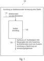
- Fig.1 shows a schematic device for 3-dimensional measurement of an object, according to an embodiment of the present invention.
- the device 100 for 3-dimensional measurement of an object is designed to receive or capture image information 110 from a measuring camera.
- the measuring camera not shown here, can be part of the device 100, for example, or can be an external component.
- the device 100 is designed in particular to receive a trigger signal that triggers, for example, a measurement output or an evaluation of the image information by an evaluation device to determine measurement results.
- the trigger signal is designated here, for example, with 120.
- the device 100 comprises a trigger device 130, which is also referred to here as a "trigger device".
- the triggering device 130 is designed to receive the image information 110 from the measuring camera and, depending on the image content of the image information, to trigger a measurement output (for example, forwarding the image information to an evaluation device for determining measurement results) or a further, more detailed evaluation of the image information by the evaluation device for determining measurement results.
- the evaluation device 130 can, for example, use the image information 110 received from the measuring camera to determine when image information from the measuring camera (or the image information 110 from the measuring camera) is used for further, detailed evaluation.
- the triggering device 130 can generate a trigger signal that either triggers a forwarding of the image information 110 or that triggers an actual use of the image information 110 for further, more detailed evaluation.
- a first stage of image processing which is carried out by the triggering device 130, can be used to decide which image information (e.g. which image from a sequence of images) is used for a further, more precise evaluation (e.g. for a 3-dimensional measurement of an object).
- the triggering device 130 can thus, for example, use image recognition (or generally depending on the image content of the image information 110) to identify a point in time at which the image information can be used for a further, more detailed evaluation. It can thus be achieved, for example, that the image information 110 is only output from a measuring camera or from an image sensor of the measuring camera to an evaluation device for determining measurement results if the triggering device 130 recognizes that the image information makes a further, more detailed evaluation appear promising.
- the evaluation device 130 can determine based on the image content of the image information whether the image information meets certain basic requirements that are required for the further, more detailed evaluation of the image information by the evaluation device to determine measurement results.
- the triggering device 130 can determine, for example, whether the image content of the image information has changed sufficiently with regard to image information used for an earlier (further) detailed evaluation. This can, for example, prevent almost identical image information from being output or evaluated multiple times.
- the triggering device 130 can be particularly useful, for example, if a suitable or optimal time for outputting the image information or for further detailed evaluation of the image information cannot be detected by other, for example mechanical, sensors. Furthermore, the detection of the suitable or optimal time for outputting or for further detailed evaluation of the image information is particularly helpful if a light source and/or a camera that are used to illuminate the object during the 3-dimensional measurement of the object are freely movable.
- the device 100 can be used, for example, in connection with a system that performs a laser light section scan of an object (for example for 3-dimensional measurement of the object).
- the laser light section scan is also referred to as a "laser light section scan”.
- the device described here for 3-dimensional measurement of an object offers the advantage in some embodiments that any positioning of a laser line (or generally a projected line) over a measurement object is possible, which enables, for example, freehand scanning.
- the device described here for 3-dimensional measurement of an object also enables independence from position sensors, for example independence from conventional mechanical position sensors that detect a relationship between an object to be detected (or measured) (or at least a support component that supports the object to be detected) and a laser line generator (or several laser line generators) and/or a measuring camera (or several measuring cameras).
- some embodiments enable optimal resolution depending on the scanning task and the surface/structure of the measurement object.
- the measuring system for example the triggering device 130 permanently (or at least over an extended period of time) carries out an image analysis based on suitable features and only outputs an image when certain predefined criteria are met, i.e., viewed from the outside, outputs a self-triggered measurement result.
- the features described below can be selected to detect a recording (or to trigger a measurement output or an evaluation of the image information by an evaluation device to determine measurement results).
- features of a laser light section can be used to detect a recording (or to trigger it). For example, it is possible to select 3-dimensional marks on the surface of a base on which the measurement object is located, or 3-dimensional marks on the measurement object (which can be seen in a laser light section, for example) to detect a recording. Alternatively or additionally, it is possible to use 2-dimensional optical properties along the laser line to detect a recording (or to trigger it). Alternatively or additionally, it is possible to select general features from a processing chain within the measuring camera to detect a recording (or to trigger it).
- 3-dimensional marks on the surface of the base on which the measuring object is located can be, for example, elevations or dents (such as a Braille code) and/or bores or holes and/or edges and steps, e.g. through a beginning of the measuring object.
- Such 3-dimensional marks on the surface of the base on which the measuring object is located, or on the measuring object can be recognized, for example, in an image of the laser light section, e.g. as a change in brightness or as deviations from a straight course of the laser light section.
- a measurement output or a further evaluation of the image information can be triggered, for example, if it is recognized in image information that shows an image of a laser light section that the laser light section has one or more 3-dimensional marks on the Surface of the base on which the measuring object is located, or intersects one or more 3-dimensional marks on the measuring object.
- certain properties of the 3-dimensional marks such as their distance or relative arrangement to one another, can also be taken into account here.
- the 3-dimensional marks can optionally also be defined by lines of predetermined or known position, so that a position of the projected line (i.e. the laser light section) can be recognized based on an image analysis, and so that the measurement output or further evaluation can be triggered based on the recognition of a certain position of the projected line (the laser light section).
- alternative or additional 2-dimensional optical properties along the laser line can be used to detect a recording (or to trigger a measurement output or further evaluation of the image information).
- a possible 2-dimensional optical property along the laser line can be a change in reflectance, which can be caused, for example, by a matt and/or a metallized surface, or which can be caused, for example, by a change in the angle of reflection of the surface.
- by evaluating an image of a laser line (which is formed by a laser light section), it can be detected when the laser light section hits a section with a matt surface or with a metallized surface or with a changed angle of reflection of the surface or passes over such a section.
- the detection of a change in reflectance can, for example, be detected simply by detecting a changed intensity of the image of the laser light section.
- the mere presence of a change in reflectance or a specific spatial pattern with which the reflectance changes can trigger a measurement output or an evaluation of the image information.
- a change in volume scattering can also be evaluated as a 2-dimensional optical property along the laser line. This can be caused, for example, by the presence of an optically dense layer on a volume-controlling material. For example, this can also be caused by the presence of copper on an FR4 material or carrier material.
- a change in volume scattering along a laser line can be detected by image processing, and the presence of the change in volume scattering, or a detected pattern of change in volume scattering along the laser line, can be used to trigger a measurement output or an evaluation of the image information.
- a change in volume scattering can be evaluated as a 2-dimensional optical property.
- the presence of a colored print or the presence of several colored prints along the laser line can also be detected and used to trigger a measurement output or to trigger the evaluation of the image information.
- One or more colored prints can, for example, match or complement a color of the laser line. This means that the presence of a colored print or several colored prints along the laser line can be detected with little effort in an image of the laser line or the laser light section and can therefore be used to trigger it.
- a laser light section or a feature of a laser light section is used to detect a recording (or to trigger a measurement output or to evaluate image information)
- general features from the processing chain within the measuring camera can also be used to trigger the trigger.
- a reliability of the detected line (or corresponding information about the reliability) can be used as a feature from the processing chain within the measuring camera.
- intermediate results from the processing of the laser line can be used (whereby such intermediate results can, for example, contain information about the reliability of the detected line).
- a start (or triggering) can take place as soon as a laser line appears in the image and/or as soon as a laser line with a specified degree of reliability is detected by image processing.
- a local width of the laser line can also be used as a general feature from the processing chain within the measuring camera to detect a recording or to trigger a measurement output or to evaluate the image information.
- the local width of the laser line is a feature coupled to the volume scattering or the reflectance.
- a gray image and feed correlation can also be used to detect a recording (or to trigger a measurement output or to trigger an evaluation of the image information).
- a A gray image can be evaluated that shows not only the projected line or the laser light section, but a more comprehensive image, for example of the object to be measured and/or the support component that supports the object to be measured.
- a correlation of successive images and a derivation of movement information can take place, whereby the movement information can then be used to trigger a measurement output or to trigger an evaluation of the image information.
- the correlation of successive images and the derivation of the movement information can, for example, take place with area illumination or with point illumination for optically scanning the surface (for example one or more points on the surface).
- area illumination for example, a area-wide image section can be evaluated, and movement information can be derived based on the evaluation of a section of the surface.
- point illumination of one or more points on the object it can be detected, for example, whether an image of the illuminated points is moving compared to a previous state.
- optical features can also be used to detect a recording or to trigger a measurement output or to trigger an evaluation of image information.
- a 3-dimensional stereo reconstruction can also be used to estimate motion (for example based on a gray image and a feed correlation).
- Distance or position information can be used to trigger a measurement process (or to trigger a measurement output or an evaluation of the image information).
- marks and color changes can also be detected as an alternative or in addition to the evaluations described above.
- marks attached to the object to be measured and transitions between areas of different colors can be evaluated in order to trigger a measurement output or to trigger an evaluation of the image information.
- an evaluation of height information e.g. of cracks and/or gaps and/or scratches
- a description of cracks and gaps can be carried out, e.g. by missing reflections with a certain local extent. This can, for example, lead to an evaluation of local jumps in the height information with a certain width. and/or an evaluation of temporal jumps in the height information with certain temporal properties.
- a recording can be detected (or a measurement output can be triggered or image information can be evaluated) based on height information.
- a recording for example of an object to be measured
- a recording can be made from different directions with several cameras or several laser line generators in different positions in order to achieve detection of a recording.
- differences in the detected properties from different directions can be used to detect a recording and/or occlusions or multiple reflections can be included for detection of a recording.
- a change in polarization can be evaluated and/or the detection of different materials can be evaluated in order to trigger a measurement output or an evaluation of the image information.
- the detection of different materials can, for example, be carried out using multispectral analysis.
- the detection of different materials can also detect the variation in the penetration depth of the laser beam. The detection of the presence of different materials can therefore, for example, be used to trigger a measurement output or an evaluation of the image information.
- an analysis of the properties (or features) presented above can be carried out on the sensor or on a downstream processing unit.
- the sensor can be designed to carry out a first analysis (for example to trigger a measurement output or to trigger a further, more detailed evaluation of the image information by an evaluation device for determining measurement results) based on analog signals from an image sensor (i.e., for example, before digitization).
- the evaluation to trigger a measurement output or to trigger an evaluation of the image information can take place in a separate processing unit (for example based on digitized signals from the image sensor).
- image processing can be performed by means of software or by means of specially developed hardware blocks.
- the results can be determined immediately with no or very little latency.
- the typically very simple evaluation carried out by the triggering device can be carried out at high speed, whereas a subsequent further, more detailed evaluation of the image information by an evaluation device for determining measurement results is usually much more complex and time-consuming.
- the detected properties can be used to decide the location of the regions of interest being examined.
- the feature determination can be controlled by an external digital interface for synchronous or asynchronous parameters, based on which the triggering is decided.
- the external digital interface can be used to determine which of the features should trigger.
- the function of the triggering device be adapted to the respective conditions of an image content (e.g. an object to be measured).
- control signals for laser line generators and lighting systems can be output directly to change or switch lighting.
- the triggering device can generate control signals for one or more laser line generators and/or for one or more other lighting systems.
- a laser line generator in response to the detection of a triggering event by the triggering device, can be controlled to change a laser line, for example to move it.
- a laser line generator can also be caused by the triggering device to activate a laser line or to increase its intensity.
- the device 100 as described in the Fig.1 described, can optionally be supplemented with many details.
- the triggering by the triggering device 130 can optionally be based on features obtained by a laser light section and/or based on features obtained by a gray image and feed correlation. Alternatively or additionally, features based on height information and/or features based on a recording from different directions can be used. Furthermore, alternatively or additionally, features based on a change in polarization and/or features based on a detection of different materials can be used.
- the feature determination can be carried out in various ways, for example on the sensor or on a downstream processing unit.
- the feature determination can be carried out in hardware or in software, but typically with a comparatively low latency in order to trigger a measurement output or a further, more detailed evaluation of the image information in a timely manner.
- control information can also be used, for example for the further, more detailed evaluation of the image information by an evaluation device to determine measurement results.
- a laser line generator and/or an illumination system can also be controlled like the trigger device.
- Fig.2 shows a schematic representation of a device for 3-dimensional measurement of an object, according to a further embodiment of the present invention.
- the device according to the Fig.2 is designated as 200 in its entirety.
- the device 200 comprises an image sensor 208, which can, for example, provide image information 210 and image information 212.
- the image information 210 can, for example, be a representation of image information in the form of analog image sensor signals.
- the image information 212 can, for example, also be a representation in the form of analog signals from the image sensor.
- the device 200 further comprises an analog preprocessing 230, which receives, for example, the image information 210 in the form of analog image sensor signals.
- the analog preprocessing 230 can, for example, implement the function of the triggering device 130 according to Fig.1
- the analog preprocessing 230 can be designed, for example, to detect lines on the carrier component that carries the object to be measured, or on the object to be measured itself, intersections between a projected line and lines on the carrier component or on the object to be measured itself and/or marks on the carrier component (base) or on the object to be measured itself (measurement object) and/or 2-dimensional optical properties along a projected line and, if necessary, to determine and output parameters that describe the detected lines, intersections, marks or optical properties.
- the analog preprocessing can be designed to detect a difference between successive images and/or a movement of the object or the object carrier and, if necessary, to describe it by parameters.
- the analog preprocessing can, for example, be carried out directly by hardware and thus, for example, evaluate the analog image sensor signals without prior digitization. At the end of the evaluation, there can be, for example, a threshold decision that enables the detection of lines, intersections, marks, optical properties or of movements. Corresponding parameters that can describe the recognized lines, intersections, marks, optical properties or movements can then be determined digitally, for example, although multi-stage digitization of image sections or entire images is preferably avoided.
- the analog preprocessing 230 can trigger an output of image information or an evaluation of the image information based on the detection of lines, intersections, marks, optical properties, differences between successive images or movements.
- the analog preprocessing 230 can, for example, generate a trigger signal 220 which, for example, corresponds to the trigger signal 120 in the device 100 according to Fig.1 can correspond.
- the trigger signal 220 can, for example, be fed to an output unit 240 which, for example, has an analog-to-digital converter and a digital interface.
- the output unit 240 receives, for example, the image information 212 from the image sensor (for example in the form of analog image sensor signals) and, in response to the trigger signal 220, triggers an analog-to-digital conversion and an output of the digitized image information via the digital interface 242.
- the trigger signal 220 can also be used to initiate image processing (e.g. further, more detailed image processing by an evaluation device for determining measurement results).
- image processing e.g. further, more detailed image processing by an evaluation device for determining measurement results.
- more detailed image processing which for example provides information about a shape of an object to be measured along a projected plane, can be carried out for example by a separate evaluation device that receives the image information via the digital interface 242.
- Fig.3 shows a schematic representation of a device for 3-dimensional measurement of an object, according to an embodiment of the present invention.
- the device according to Fig.3 is designated as a whole by 300.
- the device for 3-dimensional measurement of the object comprises a position determiner 310.
- the position determiner 310 receives image information 312 and, based on the image information 312, provides information 314 about a position of the projected line.
- the position determiner 310 is designed to receive image information that shows intersection points of a projected line with a plurality of lines of predetermined or known position, and to determine a position of the projected line based on the received image information.
- the position of the projected line can be represented, for example, by the information 314.
- the position determiner is thus designed to obtain information about the position of the projected line, for example relative to the lines of predetermined or known position, or relative to an origin of a coordinate system in which the position of the majority of lines of predetermined or known position is known, based on comparatively simple image processing, which essentially involves the detection of intersection points of the projected line with a plurality of lines in a specific or known position. Since the position determiner relies substantially on the position of the corresponding intersection points in its calculation and determines these, for example, using image processing, it is possible to determine the position of the projected line in a very simple manner without, for example, having to invest a great deal of effort in image processing.
- the device 300 according to Fig.3 is based on the realization that the intersection points of a projected line with a plurality of lines of predetermined or known position can be determined in image information with comparatively little effort, and that the information about the position of the intersection points nevertheless allows in many cases a clear and precise conclusion about the position of the projected line.
- the device 300 according to Fig.3 may optionally be supplemented by all features and functionalities described herein. It should be noted that the further features and functionalities described herein may be incorporated individually or in combination into the device 300 according to the Fig.3 can be recorded.
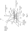
- Fig.4 shows, in the form of an oblique image, a schematic representation of a device for 3-dimensional measurement of an object.
- the device comprises a measuring camera 4101, which is arranged or aligned, for example, to record at least part of a base 4103, which can also be referred to as a carrier or carrier component, and preferably also at least part of a measurement object (for example an object to be measured).
- the measuring camera 4101 does not, however, have to be arranged stationary or fixedly guided, but can also be designed, for example, to be essentially freely movable in space.
- the device 400 further comprises a laser line generator 4102, which is designed or arranged, for example, to project a laser line onto the base 4103 and preferably also onto the measurement object 4104.
- the laser line generator 4102 can be arranged, for example, to scan or periodically sweep over a specific angular range in a plane with a laser beam and thus, for example, to cover a preceding angular range in a plane with a sufficient repetition frequency. While the laser lines generated by the laser line generator 4102 are barely recognizable in clear air due to the lack of scattering bodies, the laser line generator typically generates a "laser line" that is visible or can be recorded with the measuring camera 4101 when the laser beam hits objects.
- the laser line 4105 is essentially straight in an area in which the laser beam generated by the laser line generator 4102 hits the base 4103, assuming that the base 4103 is essentially flat. However, as soon as the base 4103 has 3-dimensional structures, these naturally reflect each other - depending on a Angle of incidence of the laser beam - reflected in deformations of the laser line 4105. Where the laser beam of the laser line generator 4102 hits the object 4104 to be measured, the laser line follows the contour of the object 4104 to be measured and is thus deformed or bent accordingly in the case of a conventional, 3-dimensional and non-flat measuring object 4104.
- the base 4103 further comprises a plurality of markers 4106 for localization, which are typically (but not necessarily) formed by straight lines.
- a first set 4107 of preferably straight lines which comprises a first line 4107a, a second line 4107b and a third line 4107c.
- the first line 4107a, the second line 4107b and the third line 4107c preferably, but not necessarily, intersect at a first intersection point 4107d.
- a second set 4108 of three lines 4108a, 4108b, 4108c which are, for example, straight, and which, for example, run through a common point 4108d.
- a different number of lines or a different geometry of the lines is also possible.
- the lines 4107a, 4107b, 4107c, 4108a, 4108b, 4108c can, for example, be permanently attached to the base 4103. Depending on the design, the lines can be painted onto the base, or the lines can also be applied to the base as 3-dimensional contours.
- the lines should preferably be designed in such a way that an intersection point of the laser line 4105 with the lines 4107a, 4107b, 4107c, 4108a, 4108b, 4108c can be clearly and distinctly recorded by the measuring camera 4101.
- the lines can be designed in such a way that the intersection points of the laser line 4105 with the lines 4107a, 4107b, 4107c, 4108a, 4108b, 4108c appear as particularly bright or particularly dark spots in an image recorded by the measuring camera 4101.
- these should preferably all lie in a plane that corresponds to a plane of the base 4103.
- there are at least four lines whereby a division into two sets of lines is not necessary (but in some embodiments contributes to an improvement in accuracy).
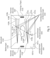
- Fig.5 shows such a top view of the arrangement 400, with some further details being described.
- the base 4103 is present, which for example carries an object 4104 to be measured.
- a laser line 4105 which is generated by the laser line generator 4102, has a substantially straight course along the surface of the base 4103.
- the markings 4106 are visible, which have for example six lines 4107a, 4107b, 4107c, 4108a, 4108b, 4108c.
- the laser line 4105 has six intersection points with the six lines 4107a-4108c. The intersection points are designated 4109a, 4109b, 4109c, 4110a, 4110b, 4110c.
- the base 4103 can be assigned, for example, a base-fixed coordinate system 4201. However, the coordinate system does not have to be explicitly shown on the base 4103.
- the base-fixed coordinate system 4201 has, for example, a first coordinate direction 4201a (e.g. x-direction) and a second coordinate direction 4201b (e.g. y-direction).
- the position of the lines 4107a, 4107b, 4107c, 4108a, 4108b and 4108c in the base-fixed coordinate system 4201 should be known.
- n i , r i can be system constants, for example.
- the line parameters can also be assigned differently to different documents 4103, for example.
- the line parameters n i , r i can be described by an information representation assigned to the document 4103.
- the document 4103 can have a bar code 4207, which describes the line parameters r i and n i of the lines 4107a, 4107b, 4107c, 4108a, 4108b, 4108c present on the base 4103.
- the device can be designed, for example, to read the bar code or barcode on the carrier 4103 in order to derive the line parameters n i , r i therefrom.
- a laser line-fixed coordinate system 4203 can also be defined, which can be defined, for example, by a coordinate origin p 0 and by a direction vector s.
- the coordinate origin p 0 and the direction vector s can be determined, for example, in the base-fixed coordinate system 4201.
- the position of the laser line-fixed coordinate system 4203 with respect to the base-fixed coordinate system 4201 is typically originally unknown (before evaluation of the system of equations explained below), so that p 0 and s are initially to be regarded as unknowns.
- Fig.4 shows a setup for localizing a laser line in relation to a measuring object by means of markings on the base (carrier).
- the localization can be determined by Fig.4 (also based on Fig.5 ) will be explained in more detail.
- the localization of the laser line in the coordinate system can be achieved by the measurement object being firmly connected to a carrier or resting on it, whereby the carrier and/or the measurement object contain one or more suitable markings.
- the carrier (and/or the measurement object) is now illuminated with a laser line (for example generated by the laser line generator 4102), which in turn is observed by a measuring camera (for example by the measuring camera 4101).
- the geometric parameters of the markings are preferably specified, for example manually or machine-readably (e.g. by means of a barcode or bar code 4207).
- information about the position of the (marking) lines 4107a, 4107b, 4107c, 4108a, 4108b, 4108c can be manually entered into the device (or position determiner), or the information about the position of the (marking) lines can be electronically read by the device (or position determiner), e.g. by recognizing the information contained in the bar code.
- the concept also includes scanning the markings (e.g. the marking lines).
- the side markings 4106 can be scanned for precise localization of the LL line (e.g. the laser line 4105) in relation to the base 4103.
- the measurement object 4104 located in between e.g. between the first group 4107 of lines and the second group 4108 of lines
- clarity is advantageous. If clarity prevails, it is possible to assign the angle and displacement of the laser line in relation to the markings.
- the lines 4107a, 4107b, 4107c, 4108a, 4108b, 4108c are preferably arranged such that the measurement object 4104 lies (or can lie) between at least two of the lines, preferably without shading any line relative to the laser line generator 4102 or relative to the measuring camera 4101. Furthermore, the lines are preferably arranged such that the intersection points 4109a-4109c, 4110a-4110c between the projected line (laser line) and the lines 4107a-4107c, 4108a-4108c can be clearly deduced from the position of the laser line 4105 relative to the lines 4107a-4107c, 4108a-4108c or relative to the coordinate system 4201 fixed to the substrate.
- the lines should preferably be chosen such that the system of equations described below is not underdetermined.
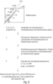
- Fig.6 shows a schematic representation of image information, such as that recorded by the measuring camera 4101, as well as subsequent image processing by a position determiner according to an embodiment of the invention.
- the image information 610 allows, for example, the identification of intersection points of the laser line with markings on the base 4103. For example, a first intersection point 4109a, a second intersection point 4109b, a third intersection point 4109c and a fourth intersection point 4110a are visible. These intersection points between the laser line and the lines 4107a, 4107b, 4107c, 4108a on the base 4103 can be recognized, for example, by simple image processing (of the position determiner) if the intersection points, for example, as particularly bright points in the image information provided by the measuring camera 4101.
- intersection points 4109a, 4109b, 4109c, 4110a can also be identified as particularly dark spots along the laser line or as particularly wide or narrow spots along the laser line in the image information provided by the measuring camera 4101, depending on the technology used to mark the lines 4107a, 4107b, 4107c, etc. on the substrate.
- the only important thing here is that the images of the intersection points 4109a, 4109b, 4109c, 4110a can be identified in the image information provided by the measuring camera with as little effort as possible.
- the coordinates of the images of the intersection points 4109a, 4109b, 4109c, 4110a in the image information can be determined by a comparatively simple image analysis.
- the intersection points can be described by 2-dimensional coordinates, for example by an x-coordinate and a y-coordinate (for example in an image coordinate system).
- a regression line can be identified that runs through the images of the intersection points 4109a, 4109b, 4109c, 4110a or that runs in such a way that a sum of distance squares of the images of the intersection points 4109a-4110a from the regression line is minimized.
- the regression line is designated 620, for example.
- a true regression line does not necessarily have to be determined. Rather, any method for identifying a line that runs at least approximately through the images of the intersection points can be used.
- a direction of the regression line can be described, for example, by a vector s, which is, for example, a unit vector. Furthermore, in a coordinate system of the image information, a coordinate origin on the regression line through the intersection points can be selected. The choice of the coordinate origin is essentially arbitrary. However, the coordinate origin should lie on the regression line 620. A choice of the coordinate origin is indicated by p 0.
- parameters k i are now determined by the position determiner, which characterize the position of the intersection points 4109a, 4109b, 4109c, 4110a (also described by vectors p 1 , p 2 , p 3 , p 4 ) or which are assigned to the position of the intersection points.
- the parameters k i can essentially be a Describe the distance of the intersection points from the coordinate origin (selected on the regression line), where a sign of the parameter k i can indicate in which direction, seen from the coordinate origin of the regression line, the respective intersection point lies.
- the position determiner evaluates image information and initially determines a position of intersection points. The position determiner then determines a straight line or regression line through the intersection points and determines a direction vector of the straight line or regression line. The position determiner then selects, for example arbitrarily or based on a predetermined rule, a point on the straight line or regression line as the coordinate origin of a "laser line-fixed coordinate system" 4203. The position determiner then determines the parameters k i , for example based on the vectorial equation mentioned above.
- the position determiner determines a position of p 0 (i.e. the coordinate origin of the laser line-fixed coordinate system) and a direction s (i.e. a direction of the laser line-fixed coordinate system) in the coordinate system of the lines of predetermined or known position (i.e. in the substrate-fixed coordinate system 4201).
- Fig.5 shows an arrangement and the evaluation of markings on the substrate.
- An important aspect of the invention (in particular the position determination) relates to the determination of crossing points between the laser line (or the projected line) 4105 and markings 106.
- crossing points also referred to as intersection points
- the determination of crossing points enables the displacement and rotation of the laser line 4105 in relation to the base 4102 to be determined.
- This enables the output of a profile (for example of the object to be measured) with a defined (or specific) change in the position of the laser line during a moving scan.
- the output of a laser line profile together with position parameters is possible.
- the start and end points of the laser line can be output in the coordinate system of the base (or the measurement object), even if the exact position of the laser line generator 4102 relative to the base 4103 cannot be determined or determined due to a mechanical guide.
- the position determiner can output the displacement and rotation of the two coordinate systems (i.e.
- the position determiner can also output the intersection points between the laser line and the markings for joint evaluation with a height profile (which can be achieved by further image evaluation and which, for example, describes a profile of the measuring object).
- the position of the laser line 4105 is determined relative to a base-fixed coordinate system 4201 by calculating the coordinate origin p 0 and a unit vector s of a laser line-fixed coordinate system 4203.
- the markings 4106 are preferably at least four straight lines applied to the base 4103, which form at least four suitable intersection points 4202, 4109a, 4109b, 4109c, 4110a, 4110b, 4110c with the laser line 4105 on the base.
- the auxiliary quantities p 0 in a coordinate system of the image information and s in a coordinate system the image information (it is preferably assumed that the image information shows a substantially undistorted image of the base 4103 or the intersection points between the laser line 4105 and the markings 4202).
- the parameters k i can be determined by the position determiner and kept ready for further calculation.
- the marking lines 4106 assigned to these intersection points e.g. lines 4107a, 4107b, 4107c, 4108a, 4108b, 4108c
- n i T p r i described ( i ⁇ N )
- the constants n i and r i are entered manually (in the position determiner or in the higher-level device) or determined using parameters or bar codes 4107.
- the system of equations is solved only for a subset of the intersection points 4202 of the laser line 4105 and the marking 4106.
- each subset is selected such that only intersection points 4202 are used that are not covered by the measuring object 4104.
- said subset is selected such that only intersection points are used that are visible in the image of the measuring camera 4105.
- a detection accuracy is estimated and this detection accuracy is taken into account when selecting said subset.
- the residuals are also determined.
- these residuals are used to perform plausibility checks.
- the residuals are used to decide whether an image from the measuring camera 4101 is discarded (or not).
- the height profile can be evaluated together with the localization data. For example, an exact position of the laser line 4105 in relation to the base or in relation to the measurement object can be determined (e.g. by the position determiner). Furthermore, a coordinate transformation of the height data (which is obtained, for example, based on a laser light section of the measurement object 4104 to be measured) into the coordinate system of the markings or the base of the measurement object is thus made possible.
- This coordinate transformation can be carried out, for example, by the device for measuring a 3-dimensional object based on the information about the position of the projected line received from the position determiner, wherein, for example, a height profile obtained by further evaluation of the image information from the measuring camera 4104 is assigned to a correct position or a correct course according to the information about the position of the projected line. If necessary, missing points can be interpolated as part of the evaluation of the height profile together with the localization data.
- height profiles that are assigned to different positions of the laser line 4105 can be combined to form an overall height profile of the object to be measured, whereby the number of individual height profiles is increased by repeatedly moving the laser line generator 4102 and/or the measuring camera 4101 past the object to be measured, which in turn can lead to an improved resolution of an overall height profile.
- the position determiner described here can use image information (e.g. from the measuring camera 4101) to determine the position of the object, e.g. Laser line generator 4102 projected line relative to a base-fixed coordinate system 4201, whereby mechanical position sensors are no longer required. Rather, the determination of the position of the laser line 4105 is carried out solely on the basis of a detection of intersection points between the laser line 4105 and markings 4202 and is based on a processing of information that describes the position of the intersection points in an ideally undistorted image of the base 4103.
- the position of the markings or lines 4106, 4107a, 4107b, 4107c, 4108a, 4108b, 4108c should preferably be known, whereby the position determiner can obtain the information, for example, via a user interface or via an evaluation of optically or electronically coded position information.
- Information about the position of the laser line 4105 can then be used in various ways.
- the information about the position of the laser line 4105 can be used, for example, to trigger a measurement output or a further, more detailed evaluation of image information (for example, to determine a height profile along a laser light section).
- the information about the position of the laser line 4105 can also be used to assign position information to a height profile obtained by a further, more detailed evaluation of the image information obtained, for example, from the measuring camera. If, for example, the position of the laser line 4105 in the substrate-fixed coordinate system 4201 is known, it can be deduced from this where a laser light section intersects an object 4104 to be measured. Thus, based on the information about the position of the laser line 4105 (or generally the projected line), it can be determined where within a model of the object 4104 to be measured a height profile obtained by a laser light section is to be set.
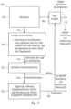
- Fig.7 shows a block diagram of a device for 3-dimensional measurement of an object, according to an embodiment of the present invention.
- the device according to the Fig.7 is designated in its entirety by 700.
- the device 700 comprises an image sensor 708, which can correspond, for example, to the image sensor 208 explained above.
- the image sensor provides, for example, an analog image sensor signal 710, which can correspond, for example, to the analog image sensor signal 210, and which can also correspond, for example, to the image information 312.
- the device 700 further comprises an analog preprocessing 716, which can be designed, for example, to detect intersection points a projected line with lines of a predetermined or known position, for example on an object or a carrier component, and to provide information 718 about a position of the intersection points within the image information.
- the device 700 further comprises a (fast) position determiner 722, which is designed, for example, to provide position information 724 based on the information 718 about the position of the intersection points in the image information, which describes, for example, a position of the projected line in relation to a carrier component (base) or in relation to an object.
- the analog preprocessing 716 and the (fast) position determiner 722 can, for example, together fulfill the function of the position determiner 310.
- the device 700 further comprises a trigger 726, which is designed, for example, to generate a trigger signal 720 when it is recognized that the projected line has a certain position (wherein the position of the projected line is described by the position information 724).
- the trigger signal 720 can, for example, correspond to the trigger signal 220.
- the analog preprocessing 716, the position determiner 722 and the triggering 726 together can fulfill the function of the analog preprocessing 230, i.e. can generate a trigger signal 720 that triggers a measurement output or a further, more detailed processing of image information.
- the device 700 here also includes, for example, an image output 740, which can correspond, for example, to the analog-digital converter/interface 240 of the device 200.
- the trigger signal 720 can output image information for further processing, for example for determining a height profile.
- the further processing which is triggered for example by the trigger signal 720 or which is triggered for example by the output of image information via the digital interface 742, can for example generate a height profile (eg along the laser line or along the laser light section) based on the image information supplied by the image sensor 708 via the digital interface 742.
- the further processing can also determine a position of the height profile based on the position information 724, which can optionally also be forwarded to the further processing.
- the device 700 as a whole can trigger further processing (e.g. a determination of a height profile along a laser line or along a laser light section) if, by means of an analog preprocessing 716, which is based for example on analog image sensor signals, intersection points of a projected line with lines of predetermined or known position are detected, and if, for example, position information 724 derived from these intersection points indicates that the projected line (laser line) is at a position at which a height profile is to be created.
- an analog preprocessing 716 which is based for example on analog image sensor signals
- intersection points of a projected line with lines of predetermined or known position are detected, and if, for example, position information 724 derived from these intersection points indicates that the projected line (laser line) is at a position at which a height profile is to be created.
- the determination of a height profile, or any other further processing that serves the 3-dimensional measurement of an object can be triggered, for example, by the trigger signal or carrier signal 720, or can be triggered, for example, simply by the output of digital image information via the digital interface 242 of the image sensor (whereby this output of image information is in turn triggered via the trigger signal 720).
- Fig.8 shows a flow chart of a method for 3-dimensional measurement of an object.
- the method 800 includes receiving 810 image information that shows intersection points of a projected line with a plurality of lines in a predetermined and known position, and determining 820 a position of the projected line based on the received image information.
- the method 800 may be supplemented with any of the steps, features, and functionalities described herein, individually or in combination.
- Fig.9 shows a flow chart of a method for 3-dimensional measurement of an object.
- the method 900 according to Fig.9 comprises receiving 910 image information from a measuring camera and triggering 920, depending on an image content of the image information, a measurement output or an evaluation of the image information by an evaluation device for determining measurement results.
- the procedure 900 according to Fig.9 may be supplemented with all steps, features and functionalities described herein, individually or in combination.
- Embodiments according to the present invention can be used, for example, for uncoupled or manual recording of 3-dimensional data (3D data) in special structures.
- the application can be for example for immobile objects, or also for objects that do not allow scanning using an incremental encoder (or no movement on a carrier component whose movement can be detected by an incremental encoder).
- This can be made possible, for example, by applying suitable markings (e.g. the markings 4202) to identify the position in the coordinate system of the base (e.g. in the base-fixed coordinate system 4201) or the measuring system.
- a trigger e.g. a trigger based on image information
- Embodiments according to the invention can also be used for surveying rails and roads.
- Embodiments according to the invention can also be used to detect and measure defects or special areas (e.g. objects to be measured). For example, an automatic, high-precision measurement can be carried out as long as an area is in the image field.
- defects or special areas e.g. objects to be measured.
- an automatic, high-precision measurement can be carried out as long as an area is in the image field.
- markings 202 can be applied to a surface of an area to be detected or measured or in a vicinity of an area to be detected or measured, which then allow a conclusion to be drawn about a position of a projected line when scanning the area to be detected.
- markings e.g. lines or linear markings
- the position of the projected line (laser line) can then be determined based on the intersection points of the projected line (laser line) with the markings.
- Embodiments according to the invention thus enable any positioning of a laser line (or a projected line) over a measurement object, which allows hands-free scanning.
- Embodiments according to the invention also allow independence from position sensors.
- Embodiments according to the invention thus enable an optimal resolution depending on the scanning task (scanning task) and the surface/structure of the measuring object.
- the inventive solution for triggering image recording differs from the prior art in that there is no electrical coupling between the propulsion of the measuring object and the measuring system, e.g. through incremental encoders or timers for a fixed time interval.
- the triggering of a measurement output from the measuring camera is done exclusively by the image content. This means that the measuring system constantly carries out an image analysis based on suitable features and only outputs an image when certain predefined criteria are met - i.e., viewed from the outside, it outputs a self-triggered measurement result.
- Fig. 5 shows an arrangement and evaluation of markings on the substrate.
- the system of equations is solved only for a subset of the intersection points (202) of the laser line (105) and the markings (106).
- this subset is selected such that only intersection points (202) are used that are not covered by the measurement object (104).
- said subset is selected such that only intersection points are used that are visible in the image of the measuring camera (101).
- a detection accuracy is estimated for each intersection point visible in the image of the measuring camera (101) and this detection accuracy is taken into account when selecting said subset.
- aspects have been described in the context of a device, it is to be understood that these aspects also represent a description of the corresponding method, so that a block or component of a device can also be understood as a corresponding method step or as a feature of a method step. Analogously, aspects described in the context of or as a method step also represent a description of a corresponding block or detail or feature of a corresponding device.
- Some or all of the method steps can be carried out by a hardware apparatus (or using a hardware apparatus), such as a microprocessor, a programmable computer, or an electronic circuit. In some embodiments, some or more of the key method steps can be carried out by such an apparatus.
- embodiments of the invention may be implemented in hardware or in software.
- the implementation may be performed using a digital storage medium, such as a floppy disk, a DVD, a Blu-ray Disc, a CD, a ROM, a PROM, an EPROM, an EEPROM or a FLASH memory, a hard disk or another magnetic or optical storage device on which electronically readable control signals are stored which can interact or interact with a programmable computer system in such a way that the respective method is carried out. Therefore, the digital storage medium can be computer-readable.
- Some embodiments according to the invention thus comprise a data carrier having electronically readable control signals capable of interacting with a programmable computer system such that one of the methods described herein is carried out.
- embodiments of the present invention may be implemented as a computer program product having a program code, wherein the program code is operable to perform one of the methods when the computer program product is run on a computer.
- the program code can, for example, also be stored on a machine-readable medium.
- inventions include the computer program for performing one of the methods described herein, wherein the computer program is stored on a machine-readable medium.
- an embodiment of the method according to the invention is thus a computer program which has a program code for carrying out one of the methods described herein when the computer program runs on a computer.
- a further embodiment of the method according to the invention is thus a data carrier (or a digital storage medium or a computer-readable medium) on which the computer program for carrying out one of the methods described herein is recorded.
- the data carrier, the digital storage medium or the computer-readable medium are typically physical and/or non-perishable or non-transitory.
- a further embodiment of the method according to the invention is thus a data stream or a sequence of signals which the computer program uses to Performing one of the methods described herein.
- the data stream or sequence of signals may, for example, be configured to be transferred over a data communication connection, for example over the Internet.
- a further embodiment comprises a processing device, for example a computer or a programmable logic device, which is configured or adapted to carry out one of the methods described herein.
- a processing device for example a computer or a programmable logic device, which is configured or adapted to carry out one of the methods described herein.
- a further embodiment comprises a computer on which the computer program for carrying out one of the methods described herein is installed.
- a further embodiment according to the invention comprises a device or a system which is designed to transmit a computer program for carrying out at least one of the methods described herein to a recipient.
- the transmission can be carried out electronically or optically, for example.
- the recipient can be, for example, a computer, a mobile device, a storage device or a similar device.
- the device or system can, for example, comprise a file server for transmitting the computer program to the recipient.
- a programmable logic device e.g., a field programmable gate array, an FPGA
- a field programmable gate array may interact with a microprocessor to perform any of the methods described herein.
- the methods are performed by any hardware device. This may be general-purpose hardware such as a computer processor (CPU) or hardware specific to the method such as an ASIC.
- the devices described herein may be implemented, for example, using a hardware apparatus, or using a computer, or using a combination of a hardware apparatus and a computer.
- the devices described herein, or any components of the devices described herein may be implemented at least partially in hardware and/or in software (computer program).
- the methods described herein may be implemented, for example, using a hardware apparatus, or using a computer, or using a combination of a hardware apparatus and a computer.
Landscapes
- Physics & Mathematics (AREA)
- Engineering & Computer Science (AREA)
- General Physics & Mathematics (AREA)
- Computer Vision & Pattern Recognition (AREA)
- Electromagnetism (AREA)
- Theoretical Computer Science (AREA)
- Computer Networks & Wireless Communication (AREA)
- Radar, Positioning & Navigation (AREA)
- Remote Sensing (AREA)
- Signal Processing (AREA)
- Optics & Photonics (AREA)
- Multimedia (AREA)
- Length Measuring Devices By Optical Means (AREA)
Claims (15)
- Dispositif (100; 200; 700) pour mesurer un objet en trois dimensions, aux caractéristiques suivantes:un moyen d'évaluation destiné à déterminer les résultats de mesure sous forme d'un profil de hauteur,un moyen de déclenchement (130; 230; 716, 722, 726) qui est conçu pour obtenir une information d'image (110) d'une caméra de mesure (4101) et pour déclencher, en fonction d'un contenu d'image de l'information d'image (110; 210; 710), une transmission de l'information d'image au moyen d'évaluation pour l'évaluation de l'information d'image par le moyen d'évaluation pour déterminer les résultats de mesure;dans lequel le moyen de déclenchement (130; 230; 716, 722, 726) est conçu pour reconnaître quand le contenu de l'image s'est décalé par rapport à un contenu d'image de référence d'au moins un décalage prédéterminé ou de plus d'un décalage prédéterminé, et pour déclencher, en fonction de la reconnaissance d'un décalage, la transmission de l'information d'image pour l'évaluation de l'information d'image par le moyen d'évaluation, dans lequelle moyen de déclenchement est conçu pour effectuer une comparaison d'un ou plusieurs signaux analogiques de capteur d'image actuels (210; 710) avec un ou plusieurs signaux analogiques de capteur d'image de référence mémorisés dans une mémoire analogique pour reconnaître une modification dans le temps d'une information d'image, dans lequel la comparaison analogique correspond à une formation d'images de différence et permet une reconnaissance d'un mouvement du contenu d'image, et pour déclencher, sur base de cette dernière, la sortie d'une version numérisée de l'information d'image à travers une interface numérique (242; 742) d'un capteur d'image de la caméra de mesure, dans lequel le moyen de déclenchement est conçu pour analyser différentes caractéristiques dans différentes zones du contenu d'image, dans lequel, lors d'une évaluation des caractéristiques dans différentes zones du contenu d'image, sont en quelque sorte considérés des contenus d'image objectivement différents, dans lequel le moyen de déclenchement est conçu pour décider les contenus d'image dans lesquels sont présentes des caractéristiques pertinentes, pour déclencher la sortie d'une version numérisée de l'information d'image.
- Dispositif selon la revendication 1, dans lequel le moyen de déclenchement est conçu pour déclencher, en fonction de la reconnaissance du déplacement, la transmission de l'information d'image pour l'évaluation de l'information d'image par le moyen d'évaluation pour déterminer les résultats de mesure, pour générer les résultats de mesure avec une certaine distance spatiale entre eux ou pour obtenir les résultats de mesure avec des distances spatiales uniformes entre eux.
- Dispositif selon la revendication 1 ou 2, dans lequel le moyen de déclenchement (130; 230; 716, 722, 726) est conçu pour effectuer une analyse d'image et pour déclencher, en fonction de l'analyse d'image, la sortie de mesure ou le déclenchement de l'évaluation de l'information d'image.
- Dispositif selon l'une des revendications 1 à 3, dans lequel le moyen de déclenchement (130; 230; 716, 722, 726) est conçu pour procéder à un prétraitement analogique des signaux analogiques du capteur d'image (710), et pour déclencher, sur base du prétraitement analogique des signaux analogiques du capteur d'image, la transmission de l'information d'image (212) pour l'évaluation de l'information d'image par un moyen d'évaluation pour déterminer les résultats de mesure.
- Dispositif selon l'une des revendications 1 à 3, dans lequel le moyen de déclenchement (130; 230; 716, 722, 726) est conçu pour déclencher une numérisation (240; 740) des signaux analogiques de capteur d'image via l'interface numérique (242; 742) du capteur d'image.
- Dispositif selon l'une des revendications 1 à 5, dans lequel le moyen de déclenchement (130; 230; 716, 722, 726) est conçu pour procéder à un traitement analogique de combinaison d'une pluralité de signaux analogiques de capteur d'image, et pour déclencher, sur base d'un résultat du traitement analogique de combinaison, la sortie d'une version numérisée de l'information d'image à travers une interface numérique (242; 742) du capteur d'image.
- Dispositif selon l'une des revendications 1 à 6, dans lequel le moyen de déclenchement (130; 230; 716, 722, 726) est conçu pour obtenir une information sur une fiabilité d'une reconnaissance de ligne ou une information sur une largeur d'une ligne et pour déclencher, en fonction de cette dernière, la transmission de l'information d'image pour l'évaluation de l'information d'image par le moyen d'évaluation pour déterminer les résultats de mesure.
- Dispositif selon l'une des revendications 1 à 7, dans lequel le moyen de déclenchement (130; 230; 716, 722, 726) est conçu pour déterminer ou pour estimer, sur base du contenu d'image, un mouvement d'une caméra (4101) qui génère l'information d'image, et/ou un déplacement d'une source de lumière (4102) qui irradie l'objet de mesure, et/ou un mouvement de l'objet de mesure, et pour déterminer ainsi un mouvement relatif entre la source de lumière et/ou le la caméra et l'objet à mesurer, et dans lequel le moyen de déclenchement est conçu pour déclencher, en fonction de la détermination ou de l'estimation du déplacement, la transmission de l'information d'image pour l'évaluation de l'information d'image par le moyen d'évaluation pour déterminer les résultats de mesure, pour déclencher, en cas de présence d'un déplacement souhaité par rapport à une détermination précédente d'un résultat de mesure, une nouvelle détermination d'un résultat de mesure pour obtenir une détermination de résultats de mesure avec une distance spatiale déterminée entre eux.
- Dispositif selon l'une des revendications 1 à 8, dans lequel le moyen de déclenchement (130; 230; 716, 722, 726) est conçu pour faire usage, lors de l'analyse du contenu de l'image, d'une reconstruction tridimensionnelle pour l'estimation de mouvement, et/ou pour effectuer une comparaison de caractéristiques de valeurs de gris dans une direction d'avance, et/ou pour détecter des marques, et/ou pour détecter des expressions de couleur, et/oudans lequel le moyen de déclenchement (130; 230; 716, 722, 726) est conçu pour évaluer, lors de l'analyse du contenu d'image, les informations de hauteur ou les informations de surface, et/oudans lequel le moyen de déclenchement (130; 230; 716, 722, 726) est conçu pour tenir compte des informations d'image qui sont enregistrées à partir de plusieurs directions différentes, et/oudans lequel le moyen de déclenchement (130; 230; 716, 722, 726) est conçu pour déterminer une ou plusieurs propriétés de polarisation ou une modification d'une ou plusieurs propriétés de polarisation et pour déclencher, en fonction de cela, la transmission de l'information d'image pour l'évaluation de l'information d'image par le moyen d'évaluation pour déterminer les résultats de mesure.
- Dispositif selon l'une des revendications 1 à 9, dans lequel le moyen de déclenchement (130; 230; 716, 722, 726) est conçu pour reconnaître, sur base du contenu d'image de l'information d'image, si une région d'intérêt de l'objet de mesure peut être mesurée ou non, et pour déclencher, en fonction de cela, la transmission de l'information d'image pour l'évaluation de l'information d'image par le moyen d'évaluation pour déterminer les résultats de mesure.
- Dispositif selon l'une des revendications 1 à 10, dans lequel le dispositif est conçu pour balayer un objet à mesurer en trois dimensions, sans qu'une caméra (4101) pour générer l'information d'image et/ou une source de lumière (4102) pour irradier l'objet de mesure ne soit guidée, ou dans lequel la caméra pour générer l'information d'image et/ou la source de lumière pour irradier l'objet de mesure est conçue pour un guidage manuel.
- Procédé (900) pour mesurer un objet en trois dimensions, aux étapes suivantes consistant à:obtenir (910) une information d'image à partir d'une caméra de mesure; etdéclencher (920), en fonction d'un contenu d'image de l'information d'image, une transmission de l'information d'image à un moyen d'évaluation pour l'évaluation de l'information d'image par le moyen d'évaluation pour déterminer les résultats de mesure sous forme d'un profil de hauteur;dans lequel est effectuée une comparaison d'un ou plusieurs signaux analogiques de capteur d'image actuels (210; 710) avec un ou plusieurs signaux analogiques de capteur d'image de référence mémorisés dans une mémoire analogique pour reconnaître un changement dans le temps d'une information d'image, dans lequel la comparaison analogique correspond à une formation d'images de différence et permet une reconnaissance d'un mouvement du contenu d'image, et dans lequel est déclenchée, sur base de cela, la sortie d'une version numérisée de l'information d'image à travers une interface numérique (242; 742) d'un capteur d'image de la caméra de mesure;dans lequel le procédé comporte par ailleurs le fait deévaluer différentes caractéristiques dans différentes zones du contenu d'image, où sont en quelque sorte considérés des contenus d'image objectivement différents,décider les contenus d'image dans lesquels sont présentes des caractéristiques pertinentes,reconnaître quand le contenu d'image a été décalé par rapport à un contenu d'image de référence d'au moins un décalage prédéterminé ou de plus d'un décalage prédéterminé, etdéclencher la transmission de l'information d'image pour l'évaluation de l'information d'image par le moyen d'évaluation pour déterminer les résultats de mesure en fonction de la reconnaissance d'un déplacement, où est déclenchée la sortie d'une version numérisée de l'information d'image.
- Procédé (900) pour mesurer un objet en trois dimensions selon la revendication 12, dans lequel sont reconnues comme des caractéristiques, à l'aide d'une découpe à la lumière laser ou d'une autre découpe à la lumière, des marques tridimensionnelles (4106, 4107a, 4107b, 4107c, 4108a, 4108b, 4108c) sur une surface ou des propriétés optiques bidimensionnelles le long d'une ligne laser (4105), et dans lequel est déclenchée par le moyen d'évaluation, en fonction de caractéristiques reconnues, la transmission de l'information d'image pour l'évaluation de l'information d'image pour déterminer les résultats de mesure.
- Programme d'ordinateur avec un code de programme pour mettre en oeuvre le procédé selon la revendication 12 ou 13, dans lequel le code de programme est efficace pour réaliser un procédé selon la revendication 12 ou 13 quand le programme d'ordinateur est exécuté sur un ordinateur.
- Système comprenant:une source de lumière qui irradie un objet;une caméra de mesure destinée à enregistrer au moins une partie de l'objet et à capturer ainsi les informations d'image (110);dans lequel le système est conçu pour effectuer un balayage de l'objet par une coupe à la lumière,dans lequel le système présente un dispositif (100; 200; 700) pour la mesure en trois dimensions de l'objet selon l'une des revendications 1 à 11.
Applications Claiming Priority (2)
| Application Number | Priority Date | Filing Date | Title |
|---|---|---|---|
| EP16161794 | 2016-03-22 | ||
| PCT/EP2017/056885 WO2017162778A1 (fr) | 2016-03-22 | 2017-03-22 | Dispositif pour mesurer un objet en 3 dimensions, procédé et programme informatique associés à déclenchement basé sur une image |
Publications (3)
| Publication Number | Publication Date |
|---|---|
| EP3433574A1 EP3433574A1 (fr) | 2019-01-30 |
| EP3433574C0 EP3433574C0 (fr) | 2024-06-26 |
| EP3433574B1 true EP3433574B1 (fr) | 2024-06-26 |
Family
ID=55628839
Family Applications (2)
| Application Number | Title | Priority Date | Filing Date |
|---|---|---|---|
| EP17712986.3A Active EP3433574B1 (fr) | 2016-03-22 | 2017-03-22 | Dispositif pour mesurer un objet en 3 dimensions, procédé et programme informatique associés à déclenchement basé sur une image |
| EP17711683.7A Active EP3433573B1 (fr) | 2016-03-22 | 2017-03-22 | Dispositif pour mesurer un objet en 3 dimensions, procédé et programme informatique associés |
Family Applications After (1)
| Application Number | Title | Priority Date | Filing Date |
|---|---|---|---|
| EP17711683.7A Active EP3433573B1 (fr) | 2016-03-22 | 2017-03-22 | Dispositif pour mesurer un objet en 3 dimensions, procédé et programme informatique associés |
Country Status (4)
| Country | Link |
|---|---|
| US (3) | US11287247B2 (fr) |
| EP (2) | EP3433574B1 (fr) |
| JP (1) | JP6886985B2 (fr) |
| WO (2) | WO2017162777A1 (fr) |
Families Citing this family (10)
| Publication number | Priority date | Publication date | Assignee | Title |
|---|---|---|---|---|
| CN106017355A (zh) * | 2016-03-22 | 2016-10-12 | 武汉武大卓越科技有限责任公司 | 一种基于线结构光的三维测量传感器 |
| EP3433574B1 (fr) * | 2016-03-22 | 2024-06-26 | Fraunhofer-Gesellschaft zur Förderung der angewandten Forschung e.V. | Dispositif pour mesurer un objet en 3 dimensions, procédé et programme informatique associés à déclenchement basé sur une image |
| PT3367333T (pt) * | 2017-02-28 | 2022-02-24 | Phenospex B V | Método de caracterização de um objecto |
| JP2020531848A (ja) * | 2017-08-28 | 2020-11-05 | トリナミクス ゲゼルシャフト ミット ベシュレンクテル ハフツング | 少なくとも一つの幾何学情報を決定するためのレンジファインダ |
| WO2019167150A1 (fr) * | 2018-02-27 | 2019-09-06 | 株式会社ニコン | Dispositif d'analyse d'image, dispositif d'analyse, dispositif de mesure de forme, procédé d'analyse d'image, procédé de détermination de conditions de mesure, procédé de mesure de forme et programme |
| CN110530869B (zh) * | 2018-05-25 | 2022-08-23 | 上海翌视信息技术有限公司 | 一种基于位置信息和图像信息的检测系统 |
| US10839560B1 (en) * | 2019-02-26 | 2020-11-17 | Facebook Technologies, Llc | Mirror reconstruction |
| CN109990714B (zh) * | 2019-04-29 | 2024-03-22 | 成都天仁民防科技有限公司 | 一种人防防护设备质量检测系统及检测方法 |
| DE102020109945A1 (de) * | 2020-04-09 | 2021-10-14 | Isra Vision Ag | Verfahren und Inspektionseinrichtung zur optischen Inspektion einer Oberfläche |
| DE102021133709A1 (de) * | 2021-12-17 | 2023-06-22 | Rooom Ag | Matte zur Durchführung eines Photogrammetrieverfahrens, Verwendung der Matte und zugehöriges Verfahren |
Family Cites Families (35)
| Publication number | Priority date | Publication date | Assignee | Title |
|---|---|---|---|---|
| JPS6016673B2 (ja) * | 1978-12-25 | 1985-04-26 | 川崎重工業株式会社 | サ−ボ系における被検体認識装置 |
| EP0228500B2 (fr) * | 1985-08-12 | 1994-12-28 | Wilhelm Hegenscheidt Gesellschaft mbH | Méthode et dispositif pour la mesure sans contact du profil d'une roue des roues d'ensembles de roues de voie ferrée |
| JP2997327B2 (ja) * | 1991-03-29 | 2000-01-11 | 大日本印刷株式会社 | 異物検査装置 |
| JPH0829135A (ja) * | 1994-07-15 | 1996-02-02 | Sumitomo Osaka Cement Co Ltd | 物品形状測定装置およびそれを用いた物品認識装置 |
| JPH0894313A (ja) * | 1994-09-22 | 1996-04-12 | Mitsubishi Electric Corp | 形状測定装置 |
| JPH08304040A (ja) * | 1995-05-11 | 1996-11-22 | Technol Res Assoc Of Medical & Welfare Apparatus | 3次元形状測定装置 |
| JP2002225237A (ja) * | 2001-01-31 | 2002-08-14 | Dainippon Printing Co Ltd | 撮像システム |
| US6625302B2 (en) * | 2001-07-13 | 2003-09-23 | Rms Research Management Systems Usa, Inc. | System and method for obtaining animal and carcass measurements |
| WO2005017450A1 (fr) * | 2003-08-11 | 2005-02-24 | Multi-Dimension Technology, Llc | Bloc etalon et systeme d'etalonnage pour scanner 3d |
| US7084989B2 (en) | 2004-04-19 | 2006-08-01 | Sick Ivp Aktiebolag | Measuring apparatus and method in a distribution system |
| EP1612509A1 (fr) * | 2004-07-01 | 2006-01-04 | Sick IVP AB | Profilomètre optique |
| US7525669B1 (en) * | 2004-07-09 | 2009-04-28 | Mohsen Abdollahi | High-speed, scanning phase-shifting profilometry using 2D CMOS sensor |
| JP4290733B2 (ja) * | 2004-08-03 | 2009-07-08 | 有限会社テクノドリーム二十一 | 3次元形状計測方法及びその装置 |
| KR100752758B1 (ko) | 2005-10-19 | 2007-08-29 | (주) 인텍플러스 | 영상 측정 장치 및 그 방법 |
| CA2528791A1 (fr) | 2005-12-01 | 2007-06-01 | Peirong Jia | Methode de mesure tridimensionnelle plein champ |
| JP5271427B2 (ja) * | 2006-10-05 | 2013-08-21 | 株式会社キーエンス | 光学式変位計、光学式変位測定方法、光学式変位測定プログラム |
| US8520920B2 (en) | 2009-11-11 | 2013-08-27 | Siemens Corporation | System for dynamically improving medical image acquisition quality |
| JP5616210B2 (ja) * | 2010-12-09 | 2014-10-29 | 株式会社ミツトヨ | 形状測定システム及び形状測定方法 |
| DE102011000304B4 (de) * | 2011-01-25 | 2016-08-04 | Data M Sheet Metal Solutions Gmbh | Kalibrierung von Laser-Lichtschnittsensoren bei gleichzeitiger Messung |
| JP6068099B2 (ja) * | 2012-11-09 | 2017-01-25 | 西日本高速道路エンジニアリング四国株式会社 | 道路構造物の表面を調査する装置 |
| US9398287B2 (en) | 2013-02-28 | 2016-07-19 | Google Technology Holdings LLC | Context-based depth sensor control |
| AU2014235971B2 (en) * | 2013-03-21 | 2016-12-08 | International Electronic Machines Corporation | Noncontact measuring device |
| JP6242098B2 (ja) | 2013-07-16 | 2017-12-06 | 株式会社キーエンス | 三次元画像処理装置、三次元画像処理方法及び三次元画像処理プログラム並びにコンピュータで読み取り可能な記録媒体及び記録した機器 |
| JP6184289B2 (ja) | 2013-10-17 | 2017-08-23 | 株式会社キーエンス | 三次元画像処理装置、三次元画像処理方法、三次元画像処理プログラム及びコンピュータで読み取り可能な記録媒体並びに記録した機器 |
| US10009549B2 (en) * | 2014-02-28 | 2018-06-26 | The Board Of Trustees Of The Leland Stanford Junior University | Imaging providing ratio pixel intensity |
| JP6581825B2 (ja) * | 2014-07-18 | 2019-09-25 | 株式会社半導体エネルギー研究所 | 表示システム |
| JP2017083234A (ja) * | 2015-10-26 | 2017-05-18 | オムロン株式会社 | 三次元形状計測装置、三次元形状計測システム、プログラム、コンピュータ読み取り可能な記録媒体、および三次元形状計測方法 |
| JP6649802B2 (ja) | 2016-02-26 | 2020-02-19 | 株式会社キーエンス | 三次元画像検査装置、三次元画像検査方法、三次元画像検査プログラム及びコンピュータで読み取り可能な記録媒体並びに記録した機器 |
| WO2017162744A1 (fr) * | 2016-03-22 | 2017-09-28 | Fraunhofer-Gesellschaft zur Förderung der angewandten Forschung e.V. | Dispositif et procédé pour combiner des signaux de mesure à partir de signaux d'éclairage |
| EP3433574B1 (fr) * | 2016-03-22 | 2024-06-26 | Fraunhofer-Gesellschaft zur Förderung der angewandten Forschung e.V. | Dispositif pour mesurer un objet en 3 dimensions, procédé et programme informatique associés à déclenchement basé sur une image |
| US10371784B2 (en) * | 2016-06-03 | 2019-08-06 | Raytheon Company | System and method for multi-sensor multi-target 3D fusion using an unbiased measurement space |
| US11014163B2 (en) * | 2017-04-14 | 2021-05-25 | Desktop Metal, Inc. | Calibration of 3D printer via computer vision |
| JP6997541B2 (ja) | 2017-05-31 | 2022-01-17 | 株式会社キーエンス | 画像検査装置、画像検査プログラム及びコンピュータで読み取り可能な記録媒体並びに記録した機器 |
| JP6961394B2 (ja) | 2017-05-31 | 2021-11-05 | 株式会社キーエンス | 画像検査装置、画像検査方法、画像検査装置の設定方法、画像検査プログラム、画像装置の設定検査プログラム及びコンピュータで読み取り可能な記録媒体並びに記録した機器 |
| JP6917781B2 (ja) | 2017-05-31 | 2021-08-11 | 株式会社キーエンス | 画像検査装置 |
-
2017
- 2017-03-22 EP EP17712986.3A patent/EP3433574B1/fr active Active
- 2017-03-22 WO PCT/EP2017/056884 patent/WO2017162777A1/fr not_active Ceased
- 2017-03-22 EP EP17711683.7A patent/EP3433573B1/fr active Active
- 2017-03-22 WO PCT/EP2017/056885 patent/WO2017162778A1/fr not_active Ceased
- 2017-03-22 JP JP2018550467A patent/JP6886985B2/ja active Active
-
2018
- 2018-09-20 US US16/137,269 patent/US11287247B2/en active Active
- 2018-09-21 US US16/137,701 patent/US11885612B2/en active Active
-
2023
- 2023-12-11 US US18/535,234 patent/US20240118074A1/en active Pending
Also Published As
| Publication number | Publication date |
|---|---|
| US11287247B2 (en) | 2022-03-29 |
| US20190033068A1 (en) | 2019-01-31 |
| EP3433573B1 (fr) | 2020-06-03 |
| WO2017162778A1 (fr) | 2017-09-28 |
| EP3433574C0 (fr) | 2024-06-26 |
| JP2019510227A (ja) | 2019-04-11 |
| WO2017162777A1 (fr) | 2017-09-28 |
| JP6886985B2 (ja) | 2021-06-16 |
| US20190025049A1 (en) | 2019-01-24 |
| US20240118074A1 (en) | 2024-04-11 |
| EP3433574A1 (fr) | 2019-01-30 |
| EP3433573A1 (fr) | 2019-01-30 |
| US11885612B2 (en) | 2024-01-30 |
Similar Documents
| Publication | Publication Date | Title |
|---|---|---|
| EP3433574B1 (fr) | Dispositif pour mesurer un objet en 3 dimensions, procédé et programme informatique associés à déclenchement basé sur une image | |
| EP3479058B1 (fr) | Procédé et dispositif servant à mesurer des dommages subis par une carrosserie | |
| DE112010004767B4 (de) | Punktwolkedaten-Verarbeitungsvorrichtung, Punktwolkedaten-Verarbeitungsverfahren und Punktwolkedaten-Verarbeitungsprogramm | |
| DE112014001459B4 (de) | Verfahren zur Ermittlung dreidimensionaler Koordinaten auf einer Oberfläche eines Objekts | |
| DE102012112322B4 (de) | Verfahren zum optischen Abtasten und Vermessen einer Umgebung | |
| DE102012112321B4 (de) | Vorrichtung zum optischen Abtasten und Vermessen einer Umgebung | |
| DE69726025T2 (de) | Verfahren und vorrichtung zum erhalten einer dreidimensionalen form | |
| EP3084347B1 (fr) | Procédé d'exécution et de contrôle d'une étape d'usinage sur une pièce | |
| DE69804128T2 (de) | Kontaktlose lage- und orientierungsmessung | |
| DE69826753T2 (de) | Optischer Profilsensor | |
| AT506110B1 (de) | Vorrichtung und verfahren zur erfassung von körpermassdaten und konturdaten | |
| DE202012104890U1 (de) | Vorrichtung zum optischen Abtasten und Vermessen einer Umgebung | |
| DE112014005911T5 (de) | Dreidimensionaler Koordinatenscanner und Betriebsverfahren | |
| DE112014001483T5 (de) | Dreidimensionaler Koordinatenscanner und Betriebsverfahren | |
| DE112013002824T5 (de) | Koordinatenmessgeräte mit entfernbaren Zusatzteilen | |
| EP0923705B1 (fr) | Procede et dispositif de determination des coordonnees spatiales d'objets | |
| EP2019281B1 (fr) | Procédé destiné au fonctionnement d'un capteur en 3D | |
| EP2865987B1 (fr) | Procédé et scanner destinés à la détermination sans contact de la position et de la forme tridimensionnelle de produits sur une surface déroulante | |
| DE102019103519B4 (de) | Vorrichtung zum Bestimmen von dimensionalen und/oder geometrischen Eigenschaften eines Messobjekts | |
| DE102007013664A1 (de) | Multisensorieller Hypothesen-basierter Objektdetektor und Objektverfolger | |
| EP2865988B1 (fr) | Capteur de profil optique | |
| DE4426424C2 (de) | Vorrichtung zur rasterstereografischen Vermessung von Körperoberflächen | |
| WO2020201217A1 (fr) | Procédé et dispositif pour déterminer des déformations sur un objet | |
| DE19626889A1 (de) | Verfahren und Vorrichtung zur Erfassung von Geometriedaten aus unterschiedlichen Beobachtungspositionen | |
| DE102023203388A1 (de) | Verfahren und system zur überprüfung einer oberfläche mit unterstützung durch künstliche intelligenz |
Legal Events
| Date | Code | Title | Description |
|---|---|---|---|
| STAA | Information on the status of an ep patent application or granted ep patent |
Free format text: STATUS: UNKNOWN |
|
| STAA | Information on the status of an ep patent application or granted ep patent |
Free format text: STATUS: THE INTERNATIONAL PUBLICATION HAS BEEN MADE |
|
| PUAI | Public reference made under article 153(3) epc to a published international application that has entered the european phase |
Free format text: ORIGINAL CODE: 0009012 |
|
| STAA | Information on the status of an ep patent application or granted ep patent |
Free format text: STATUS: REQUEST FOR EXAMINATION WAS MADE |
|
| 17P | Request for examination filed |
Effective date: 20181022 |
|
| AK | Designated contracting states |
Kind code of ref document: A1 Designated state(s): AL AT BE BG CH CY CZ DE DK EE ES FI FR GB GR HR HU IE IS IT LI LT LU LV MC MK MT NL NO PL PT RO RS SE SI SK SM TR |
|
| AX | Request for extension of the european patent |
Extension state: BA ME |
|
| DAV | Request for validation of the european patent (deleted) | ||
| DAX | Request for extension of the european patent (deleted) | ||
| RIN1 | Information on inventor provided before grant (corrected) |
Inventor name: DOEGE, JENS Inventor name: NEUDECK, WILLI Inventor name: HOPPE, CHRISTOPH |
|
| STAA | Information on the status of an ep patent application or granted ep patent |
Free format text: STATUS: EXAMINATION IS IN PROGRESS |
|
| 17Q | First examination report despatched |
Effective date: 20191203 |
|
| RAP3 | Party data changed (applicant data changed or rights of an application transferred) |
Owner name: FRAUNHOFER-GESELLSCHAFT ZUR FOERDERUNG DER ANGEWANDTEN FORSCHUNG E.V. |
|
| GRAP | Despatch of communication of intention to grant a patent |
Free format text: ORIGINAL CODE: EPIDOSNIGR1 |
|
| STAA | Information on the status of an ep patent application or granted ep patent |
Free format text: STATUS: GRANT OF PATENT IS INTENDED |
|
| INTG | Intention to grant announced |
Effective date: 20230804 |
|
| GRAJ | Information related to disapproval of communication of intention to grant by the applicant or resumption of examination proceedings by the epo deleted |
Free format text: ORIGINAL CODE: EPIDOSDIGR1 |
|
| STAA | Information on the status of an ep patent application or granted ep patent |
Free format text: STATUS: EXAMINATION IS IN PROGRESS |
|
| INTC | Intention to grant announced (deleted) | ||
| GRAP | Despatch of communication of intention to grant a patent |
Free format text: ORIGINAL CODE: EPIDOSNIGR1 |
|
| STAA | Information on the status of an ep patent application or granted ep patent |
Free format text: STATUS: GRANT OF PATENT IS INTENDED |
|
| INTG | Intention to grant announced |
Effective date: 20240122 |
|
| GRAS | Grant fee paid |
Free format text: ORIGINAL CODE: EPIDOSNIGR3 |
|
| GRAA | (expected) grant |
Free format text: ORIGINAL CODE: 0009210 |
|
| STAA | Information on the status of an ep patent application or granted ep patent |
Free format text: STATUS: THE PATENT HAS BEEN GRANTED |
|
| AK | Designated contracting states |
Kind code of ref document: B1 Designated state(s): AL AT BE BG CH CY CZ DE DK EE ES FI FR GB GR HR HU IE IS IT LI LT LU LV MC MK MT NL NO PL PT RO RS SE SI SK SM TR |
|
| REG | Reference to a national code |
Ref country code: GB Ref legal event code: FG4D Free format text: NOT ENGLISH |
|
| REG | Reference to a national code |
Ref country code: CH Ref legal event code: EP |
|
| REG | Reference to a national code |
Ref country code: DE Ref legal event code: R096 Ref document number: 502017016204 Country of ref document: DE |
|
| U01 | Request for unitary effect filed |
Effective date: 20240725 |
|
| U07 | Unitary effect registered |
Designated state(s): AT BE BG DE DK EE FI FR IT LT LU LV MT NL PT RO SE SI Effective date: 20240902 |
|
| PG25 | Lapsed in a contracting state [announced via postgrant information from national office to epo] |
Ref country code: HR Free format text: LAPSE BECAUSE OF FAILURE TO SUBMIT A TRANSLATION OF THE DESCRIPTION OR TO PAY THE FEE WITHIN THE PRESCRIBED TIME-LIMIT Effective date: 20240626 |
|
| PG25 | Lapsed in a contracting state [announced via postgrant information from national office to epo] |
Ref country code: GR Free format text: LAPSE BECAUSE OF FAILURE TO SUBMIT A TRANSLATION OF THE DESCRIPTION OR TO PAY THE FEE WITHIN THE PRESCRIBED TIME-LIMIT Effective date: 20240927 |
|
| PG25 | Lapsed in a contracting state [announced via postgrant information from national office to epo] |
Ref country code: NO Free format text: LAPSE BECAUSE OF FAILURE TO SUBMIT A TRANSLATION OF THE DESCRIPTION OR TO PAY THE FEE WITHIN THE PRESCRIBED TIME-LIMIT Effective date: 20240926 Ref country code: HR Free format text: LAPSE BECAUSE OF FAILURE TO SUBMIT A TRANSLATION OF THE DESCRIPTION OR TO PAY THE FEE WITHIN THE PRESCRIBED TIME-LIMIT Effective date: 20240626 Ref country code: GR Free format text: LAPSE BECAUSE OF FAILURE TO SUBMIT A TRANSLATION OF THE DESCRIPTION OR TO PAY THE FEE WITHIN THE PRESCRIBED TIME-LIMIT Effective date: 20240927 Ref country code: RS Free format text: LAPSE BECAUSE OF FAILURE TO SUBMIT A TRANSLATION OF THE DESCRIPTION OR TO PAY THE FEE WITHIN THE PRESCRIBED TIME-LIMIT Effective date: 20240926 |
|
| PG25 | Lapsed in a contracting state [announced via postgrant information from national office to epo] |
Ref country code: PL Free format text: LAPSE BECAUSE OF FAILURE TO SUBMIT A TRANSLATION OF THE DESCRIPTION OR TO PAY THE FEE WITHIN THE PRESCRIBED TIME-LIMIT Effective date: 20240626 |
|
| PG25 | Lapsed in a contracting state [announced via postgrant information from national office to epo] |
Ref country code: IS Free format text: LAPSE BECAUSE OF FAILURE TO SUBMIT A TRANSLATION OF THE DESCRIPTION OR TO PAY THE FEE WITHIN THE PRESCRIBED TIME-LIMIT Effective date: 20241026 |
|
| PG25 | Lapsed in a contracting state [announced via postgrant information from national office to epo] |
Ref country code: CZ Free format text: LAPSE BECAUSE OF FAILURE TO SUBMIT A TRANSLATION OF THE DESCRIPTION OR TO PAY THE FEE WITHIN THE PRESCRIBED TIME-LIMIT Effective date: 20240626 |
|
| PG25 | Lapsed in a contracting state [announced via postgrant information from national office to epo] |
Ref country code: SK Free format text: LAPSE BECAUSE OF FAILURE TO SUBMIT A TRANSLATION OF THE DESCRIPTION OR TO PAY THE FEE WITHIN THE PRESCRIBED TIME-LIMIT Effective date: 20240626 |
|
| PG25 | Lapsed in a contracting state [announced via postgrant information from national office to epo] |
Ref country code: SM Free format text: LAPSE BECAUSE OF FAILURE TO SUBMIT A TRANSLATION OF THE DESCRIPTION OR TO PAY THE FEE WITHIN THE PRESCRIBED TIME-LIMIT Effective date: 20240626 Ref country code: ES Free format text: LAPSE BECAUSE OF FAILURE TO SUBMIT A TRANSLATION OF THE DESCRIPTION OR TO PAY THE FEE WITHIN THE PRESCRIBED TIME-LIMIT Effective date: 20240626 |
|
| PG25 | Lapsed in a contracting state [announced via postgrant information from national office to epo] |
Ref country code: SM Free format text: LAPSE BECAUSE OF FAILURE TO SUBMIT A TRANSLATION OF THE DESCRIPTION OR TO PAY THE FEE WITHIN THE PRESCRIBED TIME-LIMIT Effective date: 20240626 Ref country code: SK Free format text: LAPSE BECAUSE OF FAILURE TO SUBMIT A TRANSLATION OF THE DESCRIPTION OR TO PAY THE FEE WITHIN THE PRESCRIBED TIME-LIMIT Effective date: 20240626 Ref country code: PL Free format text: LAPSE BECAUSE OF FAILURE TO SUBMIT A TRANSLATION OF THE DESCRIPTION OR TO PAY THE FEE WITHIN THE PRESCRIBED TIME-LIMIT Effective date: 20240626 Ref country code: IS Free format text: LAPSE BECAUSE OF FAILURE TO SUBMIT A TRANSLATION OF THE DESCRIPTION OR TO PAY THE FEE WITHIN THE PRESCRIBED TIME-LIMIT Effective date: 20241026 Ref country code: ES Free format text: LAPSE BECAUSE OF FAILURE TO SUBMIT A TRANSLATION OF THE DESCRIPTION OR TO PAY THE FEE WITHIN THE PRESCRIBED TIME-LIMIT Effective date: 20240626 Ref country code: CZ Free format text: LAPSE BECAUSE OF FAILURE TO SUBMIT A TRANSLATION OF THE DESCRIPTION OR TO PAY THE FEE WITHIN THE PRESCRIBED TIME-LIMIT Effective date: 20240626 |
|
| U20 | Renewal fee for the european patent with unitary effect paid |
Year of fee payment: 9 Effective date: 20250325 |
|
| PLBE | No opposition filed within time limit |
Free format text: ORIGINAL CODE: 0009261 |
|
| STAA | Information on the status of an ep patent application or granted ep patent |
Free format text: STATUS: NO OPPOSITION FILED WITHIN TIME LIMIT |
|
| 26N | No opposition filed |
Effective date: 20250327 |
|
| PG25 | Lapsed in a contracting state [announced via postgrant information from national office to epo] |
Ref country code: MC Free format text: LAPSE BECAUSE OF FAILURE TO SUBMIT A TRANSLATION OF THE DESCRIPTION OR TO PAY THE FEE WITHIN THE PRESCRIBED TIME-LIMIT Effective date: 20240626 |
|
| REG | Reference to a national code |
Ref country code: CH Ref legal event code: H13 Free format text: ST27 STATUS EVENT CODE: U-0-0-H10-H13 (AS PROVIDED BY THE NATIONAL OFFICE) Effective date: 20251023 |
|
| GBPC | Gb: european patent ceased through non-payment of renewal fee |
Effective date: 20250322 |
|
| PG25 | Lapsed in a contracting state [announced via postgrant information from national office to epo] |
Ref country code: GB Free format text: LAPSE BECAUSE OF NON-PAYMENT OF DUE FEES Effective date: 20250322 |
|
| PG25 | Lapsed in a contracting state [announced via postgrant information from national office to epo] |
Ref country code: CH Free format text: LAPSE BECAUSE OF NON-PAYMENT OF DUE FEES Effective date: 20250331 |
|
| PG25 | Lapsed in a contracting state [announced via postgrant information from national office to epo] |
Ref country code: IE Free format text: LAPSE BECAUSE OF NON-PAYMENT OF DUE FEES Effective date: 20250322 |