EP3433582B1 - Vorrichtung zur eingabe von absoluter position und ausrichtung eines eingabeelementes - Google Patents
Vorrichtung zur eingabe von absoluter position und ausrichtung eines eingabeelementes Download PDFInfo
- Publication number
- EP3433582B1 EP3433582B1 EP17714634.7A EP17714634A EP3433582B1 EP 3433582 B1 EP3433582 B1 EP 3433582B1 EP 17714634 A EP17714634 A EP 17714634A EP 3433582 B1 EP3433582 B1 EP 3433582B1
- Authority
- EP
- European Patent Office
- Prior art keywords
- sensors
- input element
- magnets
- permanent magnets
- ball
- Prior art date
- Legal status (The legal status is an assumption and is not a legal conclusion. Google has not performed a legal analysis and makes no representation as to the accuracy of the status listed.)
- Active
Links
Images
Classifications
-
- G—PHYSICS
- G01—MEASURING; TESTING
- G01D—MEASURING NOT SPECIALLY ADAPTED FOR A SPECIFIC VARIABLE; ARRANGEMENTS FOR MEASURING TWO OR MORE VARIABLES NOT COVERED IN A SINGLE OTHER SUBCLASS; TARIFF METERING APPARATUS; MEASURING OR TESTING NOT OTHERWISE PROVIDED FOR
- G01D5/00—Mechanical means for transferring the output of a sensing member; Means for converting the output of a sensing member to another variable where the form or nature of the sensing member does not constrain the means for converting; Transducers not specially adapted for a specific variable
- G01D5/12—Mechanical means for transferring the output of a sensing member; Means for converting the output of a sensing member to another variable where the form or nature of the sensing member does not constrain the means for converting; Transducers not specially adapted for a specific variable using electric or magnetic means
- G01D5/14—Mechanical means for transferring the output of a sensing member; Means for converting the output of a sensing member to another variable where the form or nature of the sensing member does not constrain the means for converting; Transducers not specially adapted for a specific variable using electric or magnetic means influencing the magnitude of a current or voltage
- G01D5/142—Mechanical means for transferring the output of a sensing member; Means for converting the output of a sensing member to another variable where the form or nature of the sensing member does not constrain the means for converting; Transducers not specially adapted for a specific variable using electric or magnetic means influencing the magnitude of a current or voltage using Hall-effect devices
- G01D5/145—Mechanical means for transferring the output of a sensing member; Means for converting the output of a sensing member to another variable where the form or nature of the sensing member does not constrain the means for converting; Transducers not specially adapted for a specific variable using electric or magnetic means influencing the magnitude of a current or voltage using Hall-effect devices influenced by the relative movement between the Hall device and magnetic fields
-
- G—PHYSICS
- G06—COMPUTING OR CALCULATING; COUNTING
- G06F—ELECTRIC DIGITAL DATA PROCESSING
- G06F3/00—Input arrangements for transferring data to be processed into a form capable of being handled by the computer; Output arrangements for transferring data from processing unit to output unit, e.g. interface arrangements
- G06F3/01—Input arrangements or combined input and output arrangements for interaction between user and computer
- G06F3/017—Gesture based interaction, e.g. based on a set of recognized hand gestures
-
- G—PHYSICS
- G06—COMPUTING OR CALCULATING; COUNTING
- G06F—ELECTRIC DIGITAL DATA PROCESSING
- G06F3/00—Input arrangements for transferring data to be processed into a form capable of being handled by the computer; Output arrangements for transferring data from processing unit to output unit, e.g. interface arrangements
- G06F3/01—Input arrangements or combined input and output arrangements for interaction between user and computer
- G06F3/03—Arrangements for converting the position or the displacement of a member into a coded form
- G06F3/033—Pointing devices displaced or positioned by the user, e.g. mice, trackballs, pens or joysticks; Accessories therefor
- G06F3/0346—Pointing devices displaced or positioned by the user, e.g. mice, trackballs, pens or joysticks; Accessories therefor with detection of the device orientation or free movement in a three-dimensional [3D] space, e.g. 3D mice, 6-DOF [six degrees of freedom] pointers using gyroscopes, accelerometers or tilt-sensors
Definitions
- the invention relates to the input of absolute position and orientation as well as displacements and rotations of an element in three-dimensional space in a computer.
- 3D mice are known in which various sensors are placed in such a way that shifts and rotations in three-dimensional space are described by pressing or twisting a ball.
- the displacement and rotation speed are determined in such systems either by measuring the displacement distance or the angle of rotation relative to a rest position or by measuring the thrust and rotation forces.
- the total displacement distance and the total angle of rotation are then determined by the duration of the pushing or twisting of the ball.
- Such methods have several disadvantages. On the one hand, only relative displacements and rotations can be determined. It is not possible to determine the absolute position and orientation in three-dimensional space.
- the ball used for input is more or less firmly connected to the input device and can only be pressed or rotated in a small area.
- US 2015/0025761 A1 discloses a device with a magnetic field sensor and an actuating device for a vehicle and a method for determining a relative position between a first component and a second component.
- US 2014/0184505 A1 describes a system for monitoring the movement of one or more magnets external to a device using the vector data from one or more magnetic vector sensors contained in the device to determine a position and / or to convey information.
- the invention is based on the object of providing a device for entering the absolute position and orientation of an input element and six degrees of freedom of movement, namely three displacements and three rotations of the input element, into a computer, in which the displacements and rotations of the input element in one large spatial area can be converted directly into shifts and rotations of an element in computer software.
- the object is achieved with a device for inputting the absolute position and alignment of an input element, containing two permanent magnets, the input element being arranged freely movable in the effective area of sensors, in that the dipole moments of the two permanent magnets of the input element are not arranged collinearly with one another and the sensors for measuring the magnetic flux density of the field generated by the two permanent magnets are arranged in two mutually orthogonal planes, with at least three sensors being arranged in each plane.
- Conventional NdFeB magnets are used as permanent magnets.
- the two permanent magnets are advantageously designed as bar magnets or particularly advantageously in spherical form as spherical magnets.
- the two permanent magnets can be arranged parallel, anti-parallel or orthogonal to one another within the input element. It is also possible to arrange the two permanent magnets at an angle.
- the distance between the permanent magnets is advantageously at least twice the sum of the largest dimensions of the two permanent magnets.
- a particularly advantageously designed input element is that it has the size and shape of a tennis ball.
- the type of arrangement of the sensors in the two levels is irrelevant, but it is advantageous if the sensors are evenly distributed in the two levels.
- AMR sensors can be used as sensors.
- Three-axis AMR compass sensors with an integrated AD converter and a measuring range of up to 400 ⁇ T can be used as advantageous AMR sensors. All sensors are advantageously connected to a microcontroller via an I2C bus.
- the microcontroller can be connected to a PC via USB.
- a ball about the size of a tennis ball.
- the input element 1 can be operated with one hand or with both hands.
- the input element 1 is a purely passive element and is not connected to the other components of the system.
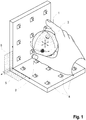
- the user can use the input element 1, which according to Fig. 1 takes the shape of a tennis ball, move freely in space.
- the magnetic flux density is measured at different spatial points in the vicinity of the input element 1. Since the magnetic field of a magnetic permanent magnet is axially symmetrical, only five lines of freedom in space, namely three displacements and two rotations, can be described by locating a single magnetic permanent magnet or several collinearly oriented permanent magnets. In order to be able to determine the sixth degree of freedom, the rotation around the axis of symmetry, the axial symmetry must be broken. This is achieved by arranging two permanent magnets in such a way that their dipole moments are not oriented collinear to one another. More precisely, an orthogonal arrangement of the two dipole moments to one another is preferred. The absolute position and alignment of the two permanent magnets is determined by a location process.
- the permanent magnets are placed at the greatest possible distance from one another, since in this way the position and orientation of the two permanent magnets can be determined more precisely in the locating process.
- the distance and the relative orientation of the permanent magnets to one another as well as the magnitudes of the magnetic dipole moments of the two permanent magnets are included in the location process as known variables.
- spherical magnets 2, 3 have been selected for the permanent magnets. In principle, however, all permanent magnet shapes are possible. How out Fig.
- the sensors 4 for measuring the magnetic flux density of the field generated by the two spherical magnets 2, 3 are arranged in two mutually orthogonal planes 5, 6, whereby the operating area is defined.
- the sensors 4 are arranged as evenly as possible in the two planes 5, 6 in order to achieve good spatial coverage.
- the arrangement of the sensors 4 selected in this way detects the magnetic field of the two spherical magnets 2, 3 of the input element 1 spatially significantly better than a sensor arrangement in only one level 5 or level 6.
- this arrangement means that the input element 1 is still easily accessible to the user and it is possible to move the input element 1 freely in the area in front of and above the two levels 5, 6.
- Fig. 1 eighteen sensors 4 were arranged.
- a small displacement of the input element 1 can be translated into a displacement speed for an element in computer software, as is also the case with conventional 3D mice.
- an element is shifted by a certain distance in the computer software. Since the free range of motion of the input element 1 in this invention is still significantly greater than with conventional 3D mice, even for compact sensor arrangements, the achievable accuracy of the displacement speed is also significantly higher, which is a significant advantage over conventional 3D mice.
- a direct translation of displacements of the input element 1 to displacements of an element in computer software can take place by means of a constant scaling factor.
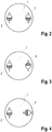
- Inexpensive three-axis AMR compass sensors with an integrated AD converter and a measuring range of up to 400 ⁇ T are used as sensors 4. All sensors 4 are connected to a microcontroller via an I2C bus, which in turn is connected to the user's computer via USB. The microcontroller queries the magnetic flux density recorded by the sensors and makes the values available for software running on the computer. The location of the input element 1 runs as a background process on the user computer. It is essential in the arrangement of the two spherical magnets 2, 3 that they are clearly spatially separated. The distance should be at least twice the sum of the largest dimensions of the two spherical magnets 2, 3. In the Figures 2 to 4 the basic three possible magnet arrangements are shown. Fig. 2 shows the parallel, Fig.
Landscapes
- Engineering & Computer Science (AREA)
- General Engineering & Computer Science (AREA)
- Theoretical Computer Science (AREA)
- Physics & Mathematics (AREA)
- General Physics & Mathematics (AREA)
- Human Computer Interaction (AREA)
- Position Input By Displaying (AREA)
Description
- Die Erfindung betrifft die Eingabe von absoluter Position und Ausrichtung sowie Verschiebungen und Drehungen eines Elementes im dreidimensionalen Raum in einen Computer.
- Zur Eingabe von Verschiebungen und Drehungen gibt es bereits verschiedene Geräte. Bekannt sind beispielsweise 3D-Mäuse, in denen verschiedene Sensoren derart platziert sind, dass durch Drücken oder Verdrehen einer Kugel Verschiebungen und Drehungen im dreidimensionalen Raum beschrieben werden. Die Verschiebungs- und Drehgeschwindigkeit werden in solchen Systemen entweder durch die Messung der Verschiebungsstrecke bzw. den Drehwinkel relativ zu einer Ruhelage oder durch die Messung der Schub- und Drehkräfte bestimmt. Die gesamte Verschiebungsstrecke und der gesamte Drehwinkel werden anschließend durch die Dauer des Drückens oder Verdrehens der Kugel bestimmt. Solche Verfahren haben mehrere Nachteile. Einerseits können nur relative Verschiebungen und Drehungen bestimmt werden. Eine Bestimmung von absoluter Position und Orientierung im dreidimensionalen Raum ist nicht möglich. Weiterhin ist die zur Eingabe verwendete Kugel mit dem Eingabegerät mehr oder weniger fest verbunden und kann nur in einem geringen Bereich gedrückt oder gedreht werden. Hierdurch sind sowohl der erreichbare Wertebereich als auch die erreichbare Genauigkeit bei der Bestimmung der Verschiebungs- bzw. Drehgeschwindigkeit begrenzt.
Als Folge wird auch die daraus berechnete Verschiebung bzw. Drehung nur ungenau beschrieben. Eine Kontrolle und Korrektur der Verschiebung bzw. Drehung erfolgt durch den Nutzer des Eingabegerätes durch entsprechende Gegenbewegungen.
Ein weiterer Nachteil bisheriger 3D-Eingabegeräte ist, dass diese natürliche Bewegungen, wie das Führen eines Stiftes oder eines Werkzeugs aufgrund der Einschränkungen in der räumlichen Bewegungsfreiheit nicht abbilden können.
Mit derDE 37 08 104 A1 wird eine Positionsmessvorrichtung vorgestellt, bei der die räumliche Position eines als Positionsindikator verwendeten Permanentmagneten bezüglich in einer Fläche angeordneten magnetoresistiven Sensoren detektierbar ist. Durch dieUS 2015/0025761 A1 wird eine Vorrichtung mit einem Magnetfeldsensor und einer Betätigungsvorrichtung für ein Fahrzeug sowie ein Verfahren zur Bestimmung einer Relativposition zwischen einer ersten Komponente und einer zweiten Komponente offenbart.
Mit derUS 2014/0184505 A1 wird ein System zum Überwachen der Bewegung eines oder mehrerer außerhalb einer Vorrichtung befindlicher Magnete unter Verwendung der Vektordaten von einem oder mehreren in der Vorrichtung enthaltenen Magnetvektorsensoren zum Bestimmen einer Position und/oder zum Übermitteln von Informationen beschrieben.
Der Erfindung liegt die Aufgabe zugrunde, eine Vorrichtung zur Eingabe von absoluter Position und Ausrichtung eines Eingabeelementes sowie von sechs Freiheitsgraden der Bewegung, nämlich drei Verschiebungen und drei Drehungen des Eingabeelements, in einen Computer zu schaffen, bei der die Verschiebungen und Drehungen des Eingabeelementes in einem großen Raumbereich direkt in Verschiebungen und Drehungen eines Elementes in einer Computersoftware umgesetzt werden. Erfindungsgemäß wird die Aufgabe mit einer Vorrichtung zur Eingabe von absoluter Position und Ausrichtung eines Eingabeelementes, enthaltend zwei Permanentmagnete, wobei das Eingabeelement im Wirkbereich von Sensoren frei bewegbar angeordnet ist, dadurch gelöst, dass die Dipolmomente der beiden Permanentmagnete des Eingabeelementes nicht kollinear zueinander orientiert angeordnet sind und die Sensoren zur Messung der magnetischen Flussdichte des von den beiden Permanentmagneten generierten Feldes in zwei zueinander orthogonalen Ebenen angeordnet sind, wobei in jeder Ebene mindestens drei Sensoren angeordnet sind. Hierbei kommen als Permanentmagnete herkömmliche NdFeB-Magnete zum Einsatz.
Die beiden Permanentmagnete sind vorteilhaft als Stabmagnete oder besonders vorteilhaft in Kugelform als Kugelmagnete ausgebildet.
Die beiden Permanentmagnete können dabei innerhalb des Eingabeelementes parallel, antiparallel oder orthogonal zueinander angeordnet werden. Auch eine unter einem Winkel stehende Anordung der beiden Permanentmagnete ist möglich.
Der Abstand zwischen den Permanentmagneten beträgt vorteilhaft mindestens das Doppelte der Summe der größten Abmaße der beiden Permanentmagneten. - Ein besonders vorteilhaft ausgestaltetes Eingabeelement besteht darin, dass es die Größe und die Form eines Tennisballes aufweist.
Grundsätzlich ist die Art der Anordnung der Sensoren in den beiden Ebenen irrelevant, jedoch ist es von Vorteil, wenn die Sensoren in den beiden Ebenen gleichmäßig verteilt angeordnet werden.
Als Sensoren können AMR-Sensoren verwendet werden.
Als vorteilhafte AMR-Sensoren können dreiachsige AMR-Kompasssensoren mit integriertem AD-Wandler und einem Messbereich bis 400 µT verwendet werden.
Alle Sensoren sind vorteilhaft über einen I2C-Bus mit einem Mikrocontroller verbunden. Der Mikrocontroller kann dabei per USB mit einem PC verbunden sein. - Die Erfindung wird nachfolgend anhand von Ausführungsbeispielen näher erläutert werden. In den dazugehörigen Zeichnungen zeigen:
- Fig. 1
- eine schematische Darstellung eines Eingabeelementes im Wirkbereich der durch die Sensoren aufgespannten beiden Ebenen,
- Fig. 2
- eine schematische Darstellung eines Eingabeelementes mit den Kugelmagneten in paralleler Anordnung,
- Fig. 3
- eine schematische Darstellung eines Eingabeelementes mit den Kugelmagneten in antiparalleler Anordnung und
- Fig. 4
- eine schematische Darstellung eines Eingabeelementes mit den Kugelmagneten in orthogonaler Anordnung.
- Als benutzerfreundliches Eingabeelement 1 wurde gemäß
Fig. 1 eine Kugel ungefähr in der Größe eines Tennisballes gewählt. Somit kann das Eingabeelement 1 einhändig oder beidhändig bedient werden. Das Eingabeelement 1 ist ein rein passives Element und nicht mit den anderen Komponenten des Systems verbunden. Dadurch kann der Benutzer das Eingabeelement 1, welches gemäßFig. 1 die Form eines Tennisballes annimmt, frei im Raum bewegen. - Für das Ortungsverfahren wird die magnetische Flussdichte an verschiedenen Raumpunkten in der Umgebung des Eingabeelementes 1 gemessen. Da das Magnetfeld eines magnetischen Permanentmagneten axialsymmetrisch ist, können durch die Ortung eines einzelnen magnetischen Permanentmagneten bzw. mehrerer kollinear orientierter Permanentmagnete nur fünf Freiheitsgerade im Raum, nämlich drei Verschiebungen und zwei Drehungen, beschrieben werden. Um den sechsten Freiheitsgrad, die Drehung um die Symmetrieachse, bestimmen zu können, muss die axiale Symmetrie gebrochen werden. Dies wird durch eine Anordnung zweier Permanentmagnete derart erreicht, dass ihre Dipolmomente nicht kollinear zueinander orientiert sind. Genauer wird eine orthogonale Anordnung der beiden Dipolmomente zueinander bevorzugt. Die absolute Position und Ausrichtung der beiden Permanentmagnete wird durch ein Ortungsverfahren ermittelt. Hierdurch sind auch die absolute Position und Orientierung des Eingabeelementes 1 eindeutig festgelegt. Weiterhin sind die Permanentmagnete in einem möglichst großen Abstand zueinander platziert, da so im Ortungsverfahren genauer die Position und Orientierung der beiden Permanentmagnete bestimmt werden kann. In das Ortungsverfahren gehen dabei als bekannte Größen der Abstand und die relative Orientierung der Permanentmagnete zueinander sowie die Beträge der magnetischen Dipolmomente der beiden Permanentmagnete ein. Für die Permanentmagnete sind in den Ausführungsbeispielen und Zeichnungen jeweils Kugelmagnete 2, 3 ausgewählt worden. Grundsätzlich sind jedoch alle Permanentmagnetformen möglich.
Wie ausFig. 1 ersichtlich, sind die Sensoren 4 zur Messung der magnetischen Flussdichte des von den beiden Kugelmagneten 2, 3 generierten Feldes in zwei zueinander orthogonalen Ebenen 5, 6 angeordnet, wodurch der Bedienbereich festgelegt ist. Die Sensoren 4 werden möglichst gleichmäßig in den beiden Ebenen 5, 6 angeordnet, um eine gute räumliche Abdeckung zu erreichen. Die so gewählte Anordnung der Sensoren 4 erfasst das Magnetfeld der beiden Kugelmagneten 2, 3 des Eingabeelementes 1 räumlich signifikant besser gegenüber einer Sensoranordnung in nur einer Ebene 5 oder einer Ebene 6. Außerdem ist durch diese Anordnung das Eingabeelement 1 weiterhin gut für den Benutzer erreichbar und es ist möglich, das Eingabeelement 1 im Bereich vor und über den beiden Ebenen 5, 6 frei zu bewegen. GemäßFig. 1 wurden achtzehn Sensoren 4 angeordnet. Das sind mehr Sensoren 4 als zwingend notwendig, um die zwei Kugelmagneten 2, 3, deren Abstand, relative Orientierung und magnetische Momente bekannt sind, zu orten. Diese Redundanz hat mehrere Vorteile. Die Genauigkeit der Ortung wird verbessert. Einerseits gibt es immer mehrere Sensoren 4, die ein deutliches Messsignal liefern, während das Messsignal anderer Sensoren 4 aufgrund ihres Messbereiches möglicherweise bereits kleiner als das Rauschsignal ist. Außerdem mitteln sich statistische Fehler teilweise heraus. Zusätzlich bietet die Redundanz eine erhöhte Ausfallsicherheit.
Abhängig von der räumlichen Ausdehnung der Sensoranordnung sind zwei Konzepte zur Übersetzung von Verschiebungen des Eingabeelementes 1 auf Verschiebungen eines Elementes in einer Computersoftware möglich. Eine kompakte Ausführung der Sensoranordnung schränkt den freien Bewegungsbereich für das Eingabeelement 1 ein. In diesem Fall kann eine kleine Verschiebung des Eingabeelements 1 in eine Verschiebungsgeschwindigkeit für ein Element in einer Computersoftware übersetzt werden, wie es auch bei konventionellen 3D-Mäusen der Fall ist. Abhängig von der Dauer, in der sich das Eingabeelement 1 in einer bestimmten Position befindet, erfolgt eine Verschiebung eines Elementes in der Computersoftware um eine bestimmte Strecke. Da der freie Bewegungsbereich des Eingabeelementes 1 in dieser Erfindung selbst für kompakte Sensoranordnungen immer noch deutlich größer ist als bei herkömmlichen 3D-Mäusen, ist auch die erreichbare Genauigkeit der Verschiebungsgeschwindigkeit deutlich höher, was einen signifikanten Vorteil gegenüber herkömmlichen 3D-Mäusen darstellt. Für eine räumlich weiter ausgedehnte Variante der Sensoranordnung, eventuell auch mit mehr als achtzehn Sensoren 4, kann eine direkte Übersetzung von Verschiebungen des Eingabeelementes 1 auf Verschiebungen eines Elementes in einer Computersoftware mittels eines konstanten Skalierungsfaktors erfolgen. Der Vorteil dieser Variante gegenüber herkömmlichen 3D-Mäusen liegt in der deutlich genaueren, da direkten Übertragung von Strecken. Unabhängig von der Ausdehnung der Sensoranordnung und damit der Beschreibung von Verschiebungen werden Drehungen des Eingabeelementes 1 direkt erfasst und können somit direkt auf Drehungen eines Elementes in einer Computersoftware übertragen werden.
Für die Messung des von den beiden Kugelmagneten 2, 3 generierten Magnetfeldes werden AMR-Sensoren verwendet. Es ist darauf zu achten, dass Messbereich und Anordnung der Sensoren 4 sowie die verwendeten Kugelmagneten 2, 3 aufeinander abgestimmt sind. In der Ausführungsform gemäßFig. 1 wurden Kugelmagneten 2, 3 mit einem magnetischen Moment von 0,150 Am2 in das Eingabeelement 1 integriert. Als Sensoren 4 kommen kostengünstige dreiachsige AMR-Kompasssensoren mit integriertem AD-Wandler und einem Messbereich bis 400 µT zum Einsatz. Alle Sensoren 4 sind über einen I2C-Bus an einen Mikrocontroller angeschlossen, der wiederum per USB an den Computer des Nutzers angebunden wird. Der Mikrocontroller fragt die von den Sensoren erfasste magnetische Flussdichte ab und stellt die Werte für eine auf dem Computer ausgeführte Software zur Verfügung. Die Ortung des Eingabeelementes 1 läuft als Hintergrundprozess auf dem Nutzerrechner.
Wesentlich bei der Anordnung der beiden Kugelmagneten 2, 3 ist, dass sie deutlich räumlich getrennt sind. Der Abstand sollte mindestens das Doppelte der Summe der größten Abmaße der beiden Kugelmagneten 2, 3 betragen.
In denFiguren 2 bis 4 sind die grundsätzlichen drei möglichen Magnetanordnungen dargestellt.Fig. 2 zeigt dabei die parallele,Fig. 3 die antiparallele undFig. 4 die orthogonale Anordnung der Kugelmagneten 2, 3 im Eingabeelement 1. Es wären aber auch jeweils von den parallelen, antiparallelen und orthogonalen Anordnungen abweichende, unter einem Winkel ungleich 180° bzw. 90° stehende Anordnungen möglich. Allein die Kenntnis der genauen Lage der Kugelmagneten 2, 3 ist Voraussetzung für Ortungsverfahren des Eingabeelementes 1. Im Übrigen ist jede andere vom Tennisball abweichende Form für das Eingabeelement 1 möglich. -
- 1
- Eingabeelement
- 2
- Kugelmagnet
- 3
- Kugelmagnet
- 4
- Sensoren
- 5
- Ebene
- 6
- Ebene
Claims (10)
- Vorrichtung zur Eingabe von absoluter Position und Ausrichtung eines Eingabeelementes (1) in einen Computer, das Eingabeelement (1) enthaltend zwei Permanentmagnete, wobei das Eingabeelement (1) im Wirkbereich von ebenfalls zur Vorrichtung gehörigen Sensoren (4) frei bewegbar angeordnet ist, dadurch gekennzeichnet, dass- die Dipolmomente der beiden Permanentmagnete des Eingabeelementes (1) nicht kollinear zueinander orientiert angeordnet sind und- die Sensoren (4) zur Messung der magnetischen Flussdichte des von den beiden Permanentmagneten generierten Feldes in zwei zueinander orthogonalen Ebenen (5, 6) angeordnet sind, wobei in jeder Ebene (5 bzw. 6) mindestens drei Sensoren (4) angeordnet sind.
- Vorrichtung nach Anspruch 1, dadurch gekennzeichnet, dass die beiden Permanentmagnete als Stabmagnete oder als Kugelmagnete (2, 3) ausgebildet sind.
- Vorrichtung nach Anspruch 2, dadurch gekennzeichnet, dass die beiden Stabmagnete oder Kugelmagnete (2, 3) parallel, antiparallel oder orthogonal zueinander angeordnet sind.
- Vorrichtung nach Anspruch 3, dadurch gekennzeichnet, dass der Abstand zwischen den Stabmagneten oder Kugelmagneten (2, 3) mindestens das Doppelte der Summe der größten Abmaße der beiden Stabmagneten oder Kugelmagneten (2, 3) beträgt.
- Vorrichtung nach Anspruch 1, dadurch gekennzeichnet, dass das Eingabeelement (1) die Größe und die Form eines Tennisballes aufweist.
- Vorrichtung nach Anspruch 1, dadurch gekennzeichnet, dass die Sensoren (4) in den beiden Ebenen (5, 6) gleichmäßig verteilt angeordnet sind.
- Vorrichtung nach Anspruch 1, dadurch gekennzeichnet, dass die Sensoren (4) AMR-Sensoren sind.
- Vorrichtung nach Anspruch 7, dadurch gekennzeichnet, dass die AMR-Sensoren dreiachsige AMR-Kompasssensoren mit integriertem AD-Wandler und einem Messbereich bis 400 µT sind.
- Vorrichtung nach einem der vorhergehenden Ansprüche, dadurch gekennzeichnet, dass die Sensoren (4) über einen I2C-Bus mit einem ebenfalls zur Vorrichtung gehörigen Mikrocontroller verbunden sind.
- Vorrichtung nach Anspruch 9, dadurch gekennzeichnet, dass der Mikrocontroller eingerichtet ist, per USB mit einem PC eine Verbindung einzugehen.
Applications Claiming Priority (2)
| Application Number | Priority Date | Filing Date | Title |
|---|---|---|---|
| DE102016105600.6A DE102016105600A1 (de) | 2016-03-24 | 2016-03-24 | Vorrichtung zur Eingabe von absoluter Position und Ausrichtung eines Eingabeelementes |
| PCT/DE2017/100184 WO2017162231A1 (de) | 2016-03-24 | 2017-03-09 | Vorrichtung zur eingabe von absoluter position und ausrichtung eines eingabeelementes |
Publications (2)
| Publication Number | Publication Date |
|---|---|
| EP3433582A1 EP3433582A1 (de) | 2019-01-30 |
| EP3433582B1 true EP3433582B1 (de) | 2020-09-16 |
Family
ID=58461024
Family Applications (1)
| Application Number | Title | Priority Date | Filing Date |
|---|---|---|---|
| EP17714634.7A Active EP3433582B1 (de) | 2016-03-24 | 2017-03-09 | Vorrichtung zur eingabe von absoluter position und ausrichtung eines eingabeelementes |
Country Status (3)
| Country | Link |
|---|---|
| EP (1) | EP3433582B1 (de) |
| DE (1) | DE102016105600A1 (de) |
| WO (1) | WO2017162231A1 (de) |
Families Citing this family (1)
| Publication number | Priority date | Publication date | Assignee | Title |
|---|---|---|---|---|
| AT522926A1 (de) * | 2019-08-21 | 2021-03-15 | Suessco Sensors Gmbh | Messen von Positionen, mechanischen Verschiebungen und Rotationen von Körpern |
Family Cites Families (4)
| Publication number | Priority date | Publication date | Assignee | Title |
|---|---|---|---|---|
| DE3708104A1 (de) | 1987-03-13 | 1988-09-22 | Bosch Gmbh Robert | Positionsmessvorrichtung |
| US6670947B2 (en) * | 2001-10-22 | 2003-12-30 | Robert William Smyth | SO3 input device |
| DE102012204634A1 (de) * | 2012-03-22 | 2013-09-26 | Zf Friedrichshafen Ag | Magnetfeldsensor, Betätigungsvorrichtung und Verfahren zur Bestimmung einer Relativposition |
| US9298281B2 (en) * | 2012-12-27 | 2016-03-29 | Correlated Magnetics Research, Llc. | Magnetic vector sensor positioning and communications system |
-
2016
- 2016-03-24 DE DE102016105600.6A patent/DE102016105600A1/de not_active Withdrawn
-
2017
- 2017-03-09 WO PCT/DE2017/100184 patent/WO2017162231A1/de not_active Ceased
- 2017-03-09 EP EP17714634.7A patent/EP3433582B1/de active Active
Non-Patent Citations (1)
| Title |
|---|
| None * |
Also Published As
| Publication number | Publication date |
|---|---|
| EP3433582A1 (de) | 2019-01-30 |
| DE102016105600A1 (de) | 2017-09-28 |
| WO2017162231A1 (de) | 2017-09-28 |
Similar Documents
| Publication | Publication Date | Title |
|---|---|---|
| EP2567837B1 (de) | Trägereinheit | |
| DE102012204634A1 (de) | Magnetfeldsensor, Betätigungsvorrichtung und Verfahren zur Bestimmung einer Relativposition | |
| DE102017206025A1 (de) | Magnetische Anordnung zur Erfassung von Relativbewegungen oder Relativpositionen | |
| DE102012202634A1 (de) | Sensoranordnung zur Erfassung von Drehwinkeln an einem rotierenden Bauteil in einem Fahrzeug | |
| DE102013019804A1 (de) | Verfahren zur Ermittlung einer Bewegung eines Objekts | |
| DE102020108981A1 (de) | Sensoranordnung zur Erfassung der absoluten Winkelposition eines Lenkelements | |
| DE102017207850A1 (de) | Winkelmessanordnung | |
| DE102015009393A1 (de) | Wegaufnehmeranordnung sowie Crashtest-Dummy | |
| DE102011001746A1 (de) | Prüfkörper sowie Verfahren zum Einmessen eines Koordinatenmessgerätes | |
| EP3433582B1 (de) | Vorrichtung zur eingabe von absoluter position und ausrichtung eines eingabeelementes | |
| EP2869029A1 (de) | Positionsmesseinrichtung | |
| DE102005025478B4 (de) | Verfahren und Vorrichtung zur Bestimmung der relativen Lage, Geschwindigkeit und/oder der Beschleunigung eines Körpers | |
| DE102020108982A1 (de) | Sensoranordnung mit einem vollständig redundanten Messsystem zur Erfassung der absoluten Winkelposition eines Lenkelements | |
| EP2778622B1 (de) | Magnetischer Positionsgeber mit zwei gegenpoligen Stabmagneten | |
| DE102007007574B3 (de) | Verfahren zum Ermitteln von Messstellen | |
| DE102021107637B4 (de) | Erfassungsvorrichtung zum Erfassen von Eingabedaten, welche auf zumindest einer Körperbewegung eines Benutzers basieren, Verfahren zum Erfassen der Eingabedaten und ein Kraftfahrzeug | |
| DE102005055905A1 (de) | Längenmessanordnung mit einem magnetischen Maßstab mit gegenläufiger Magnetisierung | |
| DE102014211054A1 (de) | Mikromechanischer Beschleunigungssensor | |
| EP2829846A1 (de) | Vorrichtung und Verfahren zur Positionsbestimmung mit Fremdfeldkompensation | |
| DE102017109531B3 (de) | Sensoranordnung und Verfahren zum Erzeugen einer Positionswechselsignalfolge | |
| DE102005009381A1 (de) | Verfahren und Vorrichtung zur Bestimmung der jeweiligen Position wenigstens eines Messortes in einem Permanentmagnetfeld | |
| DE102009002214A1 (de) | Verfahren zur Bestimmung einer Drehbewegung um eine Fahrzeugachse eines Fahrzeugs | |
| DE3912354C2 (de) | Vorrichtung zur Ermittlung von Strecken | |
| DE102014102261A1 (de) | Vorrichtung und Verfahren zur Vermessung von Messobjekten | |
| DE102012023400A1 (de) | Kanalortungssystem mit gepaarten Inertialsensoren |
Legal Events
| Date | Code | Title | Description |
|---|---|---|---|
| STAA | Information on the status of an ep patent application or granted ep patent |
Free format text: STATUS: UNKNOWN |
|
| STAA | Information on the status of an ep patent application or granted ep patent |
Free format text: STATUS: THE INTERNATIONAL PUBLICATION HAS BEEN MADE |
|
| PUAI | Public reference made under article 153(3) epc to a published international application that has entered the european phase |
Free format text: ORIGINAL CODE: 0009012 |
|
| STAA | Information on the status of an ep patent application or granted ep patent |
Free format text: STATUS: REQUEST FOR EXAMINATION WAS MADE |
|
| 17P | Request for examination filed |
Effective date: 20181012 |
|
| AK | Designated contracting states |
Kind code of ref document: A1 Designated state(s): AL AT BE BG CH CY CZ DE DK EE ES FI FR GB GR HR HU IE IS IT LI LT LU LV MC MK MT NL NO PL PT RO RS SE SI SK SM TR |
|
| AX | Request for extension of the european patent |
Extension state: BA ME |
|
| DAV | Request for validation of the european patent (deleted) | ||
| DAX | Request for extension of the european patent (deleted) | ||
| GRAP | Despatch of communication of intention to grant a patent |
Free format text: ORIGINAL CODE: EPIDOSNIGR1 |
|
| STAA | Information on the status of an ep patent application or granted ep patent |
Free format text: STATUS: GRANT OF PATENT IS INTENDED |
|
| INTG | Intention to grant announced |
Effective date: 20200406 |
|
| GRAS | Grant fee paid |
Free format text: ORIGINAL CODE: EPIDOSNIGR3 |
|
| GRAA | (expected) grant |
Free format text: ORIGINAL CODE: 0009210 |
|
| STAA | Information on the status of an ep patent application or granted ep patent |
Free format text: STATUS: THE PATENT HAS BEEN GRANTED |
|
| AK | Designated contracting states |
Kind code of ref document: B1 Designated state(s): AL AT BE BG CH CY CZ DE DK EE ES FI FR GB GR HR HU IE IS IT LI LT LU LV MC MK MT NL NO PL PT RO RS SE SI SK SM TR |
|
| REG | Reference to a national code |
Ref country code: GB Ref legal event code: FG4D Free format text: NOT ENGLISH |
|
| REG | Reference to a national code |
Ref country code: CH Ref legal event code: EP |
|
| REG | Reference to a national code |
Ref country code: DE Ref legal event code: R096 Ref document number: 502017007293 Country of ref document: DE |
|
| REG | Reference to a national code |
Ref country code: IE Ref legal event code: FG4D Free format text: LANGUAGE OF EP DOCUMENT: GERMAN |
|
| REG | Reference to a national code |
Ref country code: AT Ref legal event code: REF Ref document number: 1314548 Country of ref document: AT Kind code of ref document: T Effective date: 20201015 |
|
| PG25 | Lapsed in a contracting state [announced via postgrant information from national office to epo] |
Ref country code: NO Free format text: LAPSE BECAUSE OF FAILURE TO SUBMIT A TRANSLATION OF THE DESCRIPTION OR TO PAY THE FEE WITHIN THE PRESCRIBED TIME-LIMIT Effective date: 20201216 Ref country code: GR Free format text: LAPSE BECAUSE OF FAILURE TO SUBMIT A TRANSLATION OF THE DESCRIPTION OR TO PAY THE FEE WITHIN THE PRESCRIBED TIME-LIMIT Effective date: 20201217 Ref country code: HR Free format text: LAPSE BECAUSE OF FAILURE TO SUBMIT A TRANSLATION OF THE DESCRIPTION OR TO PAY THE FEE WITHIN THE PRESCRIBED TIME-LIMIT Effective date: 20200916 Ref country code: SE Free format text: LAPSE BECAUSE OF FAILURE TO SUBMIT A TRANSLATION OF THE DESCRIPTION OR TO PAY THE FEE WITHIN THE PRESCRIBED TIME-LIMIT Effective date: 20200916 Ref country code: FI Free format text: LAPSE BECAUSE OF FAILURE TO SUBMIT A TRANSLATION OF THE DESCRIPTION OR TO PAY THE FEE WITHIN THE PRESCRIBED TIME-LIMIT Effective date: 20200916 Ref country code: BG Free format text: LAPSE BECAUSE OF FAILURE TO SUBMIT A TRANSLATION OF THE DESCRIPTION OR TO PAY THE FEE WITHIN THE PRESCRIBED TIME-LIMIT Effective date: 20201216 |
|
| REG | Reference to a national code |
Ref country code: NL Ref legal event code: MP Effective date: 20200916 |
|
| PG25 | Lapsed in a contracting state [announced via postgrant information from national office to epo] |
Ref country code: LV Free format text: LAPSE BECAUSE OF FAILURE TO SUBMIT A TRANSLATION OF THE DESCRIPTION OR TO PAY THE FEE WITHIN THE PRESCRIBED TIME-LIMIT Effective date: 20200916 Ref country code: RS Free format text: LAPSE BECAUSE OF FAILURE TO SUBMIT A TRANSLATION OF THE DESCRIPTION OR TO PAY THE FEE WITHIN THE PRESCRIBED TIME-LIMIT Effective date: 20200916 |
|
| REG | Reference to a national code |
Ref country code: LT Ref legal event code: MG4D |
|
| PG25 | Lapsed in a contracting state [announced via postgrant information from national office to epo] |
Ref country code: SM Free format text: LAPSE BECAUSE OF FAILURE TO SUBMIT A TRANSLATION OF THE DESCRIPTION OR TO PAY THE FEE WITHIN THE PRESCRIBED TIME-LIMIT Effective date: 20200916 Ref country code: EE Free format text: LAPSE BECAUSE OF FAILURE TO SUBMIT A TRANSLATION OF THE DESCRIPTION OR TO PAY THE FEE WITHIN THE PRESCRIBED TIME-LIMIT Effective date: 20200916 Ref country code: LT Free format text: LAPSE BECAUSE OF FAILURE TO SUBMIT A TRANSLATION OF THE DESCRIPTION OR TO PAY THE FEE WITHIN THE PRESCRIBED TIME-LIMIT Effective date: 20200916 Ref country code: CZ Free format text: LAPSE BECAUSE OF FAILURE TO SUBMIT A TRANSLATION OF THE DESCRIPTION OR TO PAY THE FEE WITHIN THE PRESCRIBED TIME-LIMIT Effective date: 20200916 Ref country code: PT Free format text: LAPSE BECAUSE OF FAILURE TO SUBMIT A TRANSLATION OF THE DESCRIPTION OR TO PAY THE FEE WITHIN THE PRESCRIBED TIME-LIMIT Effective date: 20210118 Ref country code: RO Free format text: LAPSE BECAUSE OF FAILURE TO SUBMIT A TRANSLATION OF THE DESCRIPTION OR TO PAY THE FEE WITHIN THE PRESCRIBED TIME-LIMIT Effective date: 20200916 |
|
| PG25 | Lapsed in a contracting state [announced via postgrant information from national office to epo] |
Ref country code: IS Free format text: LAPSE BECAUSE OF FAILURE TO SUBMIT A TRANSLATION OF THE DESCRIPTION OR TO PAY THE FEE WITHIN THE PRESCRIBED TIME-LIMIT Effective date: 20210116 Ref country code: PL Free format text: LAPSE BECAUSE OF FAILURE TO SUBMIT A TRANSLATION OF THE DESCRIPTION OR TO PAY THE FEE WITHIN THE PRESCRIBED TIME-LIMIT Effective date: 20200916 Ref country code: AL Free format text: LAPSE BECAUSE OF FAILURE TO SUBMIT A TRANSLATION OF THE DESCRIPTION OR TO PAY THE FEE WITHIN THE PRESCRIBED TIME-LIMIT Effective date: 20200916 Ref country code: ES Free format text: LAPSE BECAUSE OF FAILURE TO SUBMIT A TRANSLATION OF THE DESCRIPTION OR TO PAY THE FEE WITHIN THE PRESCRIBED TIME-LIMIT Effective date: 20200916 |
|
| REG | Reference to a national code |
Ref country code: DE Ref legal event code: R097 Ref document number: 502017007293 Country of ref document: DE |
|
| PG25 | Lapsed in a contracting state [announced via postgrant information from national office to epo] |
Ref country code: SK Free format text: LAPSE BECAUSE OF FAILURE TO SUBMIT A TRANSLATION OF THE DESCRIPTION OR TO PAY THE FEE WITHIN THE PRESCRIBED TIME-LIMIT Effective date: 20200916 |
|
| PLBE | No opposition filed within time limit |
Free format text: ORIGINAL CODE: 0009261 |
|
| STAA | Information on the status of an ep patent application or granted ep patent |
Free format text: STATUS: NO OPPOSITION FILED WITHIN TIME LIMIT |
|
| 26N | No opposition filed |
Effective date: 20210617 |
|
| PG25 | Lapsed in a contracting state [announced via postgrant information from national office to epo] |
Ref country code: DK Free format text: LAPSE BECAUSE OF FAILURE TO SUBMIT A TRANSLATION OF THE DESCRIPTION OR TO PAY THE FEE WITHIN THE PRESCRIBED TIME-LIMIT Effective date: 20200916 Ref country code: SI Free format text: LAPSE BECAUSE OF FAILURE TO SUBMIT A TRANSLATION OF THE DESCRIPTION OR TO PAY THE FEE WITHIN THE PRESCRIBED TIME-LIMIT Effective date: 20200916 |
|
| PG25 | Lapsed in a contracting state [announced via postgrant information from national office to epo] |
Ref country code: MC Free format text: LAPSE BECAUSE OF FAILURE TO SUBMIT A TRANSLATION OF THE DESCRIPTION OR TO PAY THE FEE WITHIN THE PRESCRIBED TIME-LIMIT Effective date: 20200916 |
|
| REG | Reference to a national code |
Ref country code: CH Ref legal event code: PL |
|
| REG | Reference to a national code |
Ref country code: BE Ref legal event code: MM Effective date: 20210331 |
|
| PG25 | Lapsed in a contracting state [announced via postgrant information from national office to epo] |
Ref country code: LU Free format text: LAPSE BECAUSE OF NON-PAYMENT OF DUE FEES Effective date: 20210309 Ref country code: LI Free format text: LAPSE BECAUSE OF NON-PAYMENT OF DUE FEES Effective date: 20210331 Ref country code: CH Free format text: LAPSE BECAUSE OF NON-PAYMENT OF DUE FEES Effective date: 20210331 Ref country code: IE Free format text: LAPSE BECAUSE OF NON-PAYMENT OF DUE FEES Effective date: 20210309 |
|
| PG25 | Lapsed in a contracting state [announced via postgrant information from national office to epo] |
Ref country code: BE Free format text: LAPSE BECAUSE OF NON-PAYMENT OF DUE FEES Effective date: 20210331 |
|
| PG25 | Lapsed in a contracting state [announced via postgrant information from national office to epo] |
Ref country code: NL Free format text: LAPSE BECAUSE OF NON-PAYMENT OF DUE FEES Effective date: 20200923 Ref country code: CY Free format text: LAPSE BECAUSE OF FAILURE TO SUBMIT A TRANSLATION OF THE DESCRIPTION OR TO PAY THE FEE WITHIN THE PRESCRIBED TIME-LIMIT Effective date: 20200916 |
|
| P01 | Opt-out of the competence of the unified patent court (upc) registered |
Effective date: 20230606 |
|
| PG25 | Lapsed in a contracting state [announced via postgrant information from national office to epo] |
Ref country code: HU Free format text: LAPSE BECAUSE OF FAILURE TO SUBMIT A TRANSLATION OF THE DESCRIPTION OR TO PAY THE FEE WITHIN THE PRESCRIBED TIME-LIMIT; INVALID AB INITIO Effective date: 20170309 |
|
| REG | Reference to a national code |
Ref country code: DE Ref legal event code: R082 Ref document number: 502017007293 Country of ref document: DE Representative=s name: GLEIM PETRI PATENT- UND RECHTSANWALTSPARTNERSC, DE |
|
| PG25 | Lapsed in a contracting state [announced via postgrant information from national office to epo] |
Ref country code: MK Free format text: LAPSE BECAUSE OF FAILURE TO SUBMIT A TRANSLATION OF THE DESCRIPTION OR TO PAY THE FEE WITHIN THE PRESCRIBED TIME-LIMIT Effective date: 20200916 |
|
| PG25 | Lapsed in a contracting state [announced via postgrant information from national office to epo] |
Ref country code: MT Free format text: LAPSE BECAUSE OF FAILURE TO SUBMIT A TRANSLATION OF THE DESCRIPTION OR TO PAY THE FEE WITHIN THE PRESCRIBED TIME-LIMIT Effective date: 20200916 |
|
| PG25 | Lapsed in a contracting state [announced via postgrant information from national office to epo] |
Ref country code: TR Free format text: LAPSE BECAUSE OF FAILURE TO SUBMIT A TRANSLATION OF THE DESCRIPTION OR TO PAY THE FEE WITHIN THE PRESCRIBED TIME-LIMIT Effective date: 20200916 |
|
| PGFP | Annual fee paid to national office [announced via postgrant information from national office to epo] |
Ref country code: GB Payment date: 20260324 Year of fee payment: 10 |
|
| PGFP | Annual fee paid to national office [announced via postgrant information from national office to epo] |
Ref country code: DE Payment date: 20260319 Year of fee payment: 10 |
|
| PGFP | Annual fee paid to national office [announced via postgrant information from national office to epo] |
Ref country code: AT Payment date: 20260320 Year of fee payment: 10 |
|
| PGFP | Annual fee paid to national office [announced via postgrant information from national office to epo] |
Ref country code: IT Payment date: 20260324 Year of fee payment: 10 |
|
| PGFP | Annual fee paid to national office [announced via postgrant information from national office to epo] |
Ref country code: FR Payment date: 20260320 Year of fee payment: 10 |