EP3434096A2 - Draper-plattform mit entfernbarer zentraler walzenablenkplatte - Google Patents
Draper-plattform mit entfernbarer zentraler walzenablenkplatte Download PDFInfo
- Publication number
- EP3434096A2 EP3434096A2 EP18185775.6A EP18185775A EP3434096A2 EP 3434096 A2 EP3434096 A2 EP 3434096A2 EP 18185775 A EP18185775 A EP 18185775A EP 3434096 A2 EP3434096 A2 EP 3434096A2
- Authority
- EP
- European Patent Office
- Prior art keywords
- top cross
- central roller
- cross auger
- roller baffle
- crop
- Prior art date
- Legal status (The legal status is an assumption and is not a legal conclusion. Google has not performed a legal analysis and makes no representation as to the accuracy of the status listed.)
- Granted
Links
Images






Classifications
-
- A—HUMAN NECESSITIES
- A01—AGRICULTURE; FORESTRY; ANIMAL HUSBANDRY; HUNTING; TRAPPING; FISHING
- A01D—HARVESTING; MOWING
- A01D61/00—Elevators or conveyors for binders or combines
- A01D61/008—Elevators or conveyors for binders or combines for longitudinal conveying, especially for combines
-
- A—HUMAN NECESSITIES
- A01—AGRICULTURE; FORESTRY; ANIMAL HUSBANDRY; HUNTING; TRAPPING; FISHING
- A01D—HARVESTING; MOWING
- A01D61/00—Elevators or conveyors for binders or combines
- A01D61/002—Elevators or conveyors for binders or combines transversal conveying devices
- A01D61/006—Elevators or conveyors for binders or combines transversal conveying devices with rollers, e.g. adjustable
-
- A—HUMAN NECESSITIES
- A01—AGRICULTURE; FORESTRY; ANIMAL HUSBANDRY; HUNTING; TRAPPING; FISHING
- A01D—HARVESTING; MOWING
- A01D41/00—Combines, i.e. harvesters or mowers combined with threshing devices
- A01D41/12—Details of combines
- A01D41/14—Mowing tables
- A01D41/142—Header drives
-
- A—HUMAN NECESSITIES
- A01—AGRICULTURE; FORESTRY; ANIMAL HUSBANDRY; HUNTING; TRAPPING; FISHING
- A01D—HARVESTING; MOWING
- A01D61/00—Elevators or conveyors for binders or combines
- A01D61/002—Elevators or conveyors for binders or combines transversal conveying devices
- A01D61/004—Elevators or conveyors for binders or combines transversal conveying devices with cylindrical tools
-
- A—HUMAN NECESSITIES
- A01—AGRICULTURE; FORESTRY; ANIMAL HUSBANDRY; HUNTING; TRAPPING; FISHING
- A01D—HARVESTING; MOWING
- A01D61/00—Elevators or conveyors for binders or combines
- A01D61/02—Endless belts
-
- A—HUMAN NECESSITIES
- A01—AGRICULTURE; FORESTRY; ANIMAL HUSBANDRY; HUNTING; TRAPPING; FISHING
- A01D—HARVESTING; MOWING
- A01D34/00—Mowers; Mowing apparatus of harvesters
- A01D34/01—Mowers; Mowing apparatus of harvesters characterised by features relating to the type of cutting apparatus
- A01D34/02—Mowers; Mowing apparatus of harvesters characterised by features relating to the type of cutting apparatus having reciprocating cutters
- A01D34/03—Mowers; Mowing apparatus of harvesters characterised by features relating to the type of cutting apparatus having reciprocating cutters mounted on a vehicle, e.g. a tractor, or drawn by an animal or a vehicle
- A01D34/04—Mowers; Mowing apparatus of harvesters characterised by features relating to the type of cutting apparatus having reciprocating cutters mounted on a vehicle, e.g. a tractor, or drawn by an animal or a vehicle with cutters at the front
-
- A—HUMAN NECESSITIES
- A01—AGRICULTURE; FORESTRY; ANIMAL HUSBANDRY; HUNTING; TRAPPING; FISHING
- A01D—HARVESTING; MOWING
- A01D41/00—Combines, i.e. harvesters or mowers combined with threshing devices
- A01D41/12—Details of combines
- A01D41/14—Mowing tables
Definitions
- Combines also known as harvesters, are self-propelled vehicles used for harvesting and threshing agricultural crop in a field. Such combines typically utilize a header which initially severs or separates the crop from the underlying growing medium.
- a header is a draper platform which severs the crop with a reciprocating knife and which gathers the cut crop onto left and right conveyor belts that convey the cut crop to a central conveyor belt that cooperates with a conveyor drum to direct the cut crop into a feeder house of the combine.
- Some draper platforms include a top cross auger in the form of a single elongate tube having oppositely directed exterior veins on opposite sides of the central conveyor so as to further assist in moving cut crops to the central conveyor.
- portions of the tube above the conveyor drum include outwardly projecting tines to assist in directing cut crop material into the feeder house.
- Those draper platforms that include such a single top cross auger may not be well-suited for all crop conditions.
- the presence of the top cross auger over the conveyor drum may result in crop loss or crop damage.
- those portions of the existing top cross auger over the conveyor drum that interact with the cut crop may be too aggressive.
- those portions of the existing top cross auger over the conveyor drum that interact with the cut crop may not be sufficiently aggressive.
- an example draper platform for a combine that provides two separate top cross augers with a central roller baffle above the conveyor drum removably mounted or supported between the two separate top cross augers.
- the central roller baffle may be omitted, providing a volume between the two separate top cross augers above the conveyor drum.
- the central roller baffle may be removably mounted between the two separate top cross augers.
- a first central roller baffle that interacts with the crops in a first manner, a first level of aggressiveness may be removably mounted between the two separate top cross augers.
- a second central roller baffle that interacts with crops in a second different manner, a second different level of aggressiveness may be removably mounted between the two separate top cross augers.
- the example draper system provides an operator with the ability to customize crop interaction of the draper platform for different crop conditions by completely removing the central roller baffle or by selecting and removably mounting one of many differently configured central roller baffles between the two top cross augers.
- the draper platform may include a frame, a center belt conveyor to carry cut crop material rearwardly towards a center opening in the frame through which crop may be fed into a feeder house, a left side belt conveyor to carry cut crop material to the center belt conveyor, a right side belt conveyor to carry cut crop material to the center belt conveyor, at least one elongate reciprocating knife assembly extending along a front edge of each of the center belt conveyor, the left side belt conveyor and the right side belt conveyor, a left side top cross auger above the left side belt conveyor, the left side top cross auger having a right inner end, a right side top cross auger above the right side belt conveyor, the right side top cross auger having a left inner end opposite to and spaced from the right inner end and a conveyor drum above the center belt conveyor below a space between the right inner end and the left inner end.
- the method may include supporting a first top cross auger and a second top cross auger in a spaced apart relationship above conveyor belts on a draper platform for a combine and removably mounting a central roller baffle between the two top cross augers above a conveyor drum.
- an example central roller baffle may include an elongate crop engaging member extending along an axis for rotation about the axis, the crop engaging member having a first axial end and a second axial end, a first coupler on the first end to releasably mount the first and to an inner end of a first top cross auger and a second coupler on the second end to releasably mount the second end to an inner end of a second top cross auger.
- the term “coupled” shall mean the joining of two members directly or indirectly to one another. Such joining may be stationary in nature or movable in nature. Such joining may be achieved with the two members or the two members and any additional intermediate members being integrally formed as a single unitary body with one another or with the two members or the two members and any additional intermediate member being attached to one another. Such joining may be permanent in nature or alternatively may be removable or releasable in nature.
- the term “operably coupled” shall mean that two members are directly or indirectly joined such that motion may be transmitted from one member to the other member directly or via intermediate members.
- the term “releasably” or “removably” with respect to an attachment or coupling of two structures means that the two structures may be repeatedly connected and disconnected to and from one another without material damage to either of the two structures or their functioning.
- the phrase “configured to” denotes an actual state of configuration that fundamentally ties the stated function/use to the physical characteristics of the feature proceeding the phrase “configured to”.
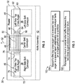
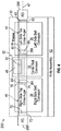
- FIGs 1 and 2 are schematic diagrams illustrating portions of an example draper platform 30 for use in a combine harvester. Draper platform 30 provides an operator with the opportunity to customize characteristics of the draper platform depending upon crop conditions by removing or selectively utilizing one of a plurality of different central roller baffles.
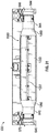
- Figure 1 illustrates draper platform 30 without a central roller baffle.
- Figure 2 illustrate a platform 30 with removably mounted or supported central roller baffle.
- Draper platform 30 comprises frame 32, center belt conveyor 34, left side belt conveyor 36, right side belt conveyor 38, reciprocating knife assembly 42 left side top cross auger 44, right side top cross auger 46 and conveyor drum 48.
- Frame 32 comprises an arrangement of panels, beams, brackets and the like supporting the remaining components of platform 32.
- Frame 32 is configured to be mounted or coupled to a feeder house of a combine in a permanent or removable fashion.
- Frame 32 includes a rear center opening 50 through which crop may be fed to the feeder house.
- Center belt conveyor 34 comprises an endless conveyor belt situated directly in front of center opening 50 between left side conveyor belt 36 and right side conveyor belt 38, behind knife assembly 42.
- Center conveyor belt 34 is operably coupled to a source of torque, a rotary drive, that drives center belt conveyor 34 rollers or other support structures so as to carry or convey crop material cut by knife assembly 42 in a rearward direction as indicated by arrow 52 through opening 50 to the feeder house (not shown) of the combine.
- Left side conveyor belt 36 extends on the left side of center belt conveyor 34 (as seen from behind draper platform 30).
- Left side conveyor belt 36 comprises an endless web or conveyor belt operably coupled to a source of torque or rotary drive so as to carry the crop material cut by knife assembly 42 toward center belt conveyor 34 in the direction indicated by arrow 54.
- Right side conveyor belt 38 extends on the right side of center belt conveyor 34 (as seen from behind draper platform 30).
- Right side conveyor belt 38 comprises an endless web or conveyor belt operably coupled to a source of torque or rotary drive so as to carry the crop material cut by knife assembly 42 toward center belt conveyor 34 in the direction indicated by arrow 56.
- Knife assembly 42 comprises at least one elongate reciprocating knife assembly extending along a front edge of platform 30. Knife assembly 42 cuts or severs the crop from its growing medium.
- knife assembly 42 comprises a single knife assembly extending across the entire front of platform 30.
- knife assembly 42 may comprise multiple subsections or sub knife assemblies that collectively extend across the front of platform 30.
- One example of a knife assembly 42 may comprise a cutter bar and knife guards that guide a reciprocating knife or knife sections.
- platform 30 may additionally include at least one reel that gathers the crop and directs the crop towards knife assembly 42 and onto conveyors 34, 36 and 38.
- Left side top cross auger 44 comprises an auger rotatably supported proximate a rear of frame 32 above left side conveyor 36.
- Left side top cross auger 44 is located on a left side (as seen from behind platform 30) of center belt conveyor 34.
- Left side top cross auger 44 has opposite end portions that are journaled.
- Left side top cross auger 44 has an outer end 60 supported by a journal support 62 and an inner journaled end 64 rotatably supported by journal support 66.
- Journal supports 62 and 66 rotationally support ends 60 and 64 of left side top cross auger, respectively.
- Journal supports 62 and 66 may comprise bearings and associated bearing races that rotationally support a shaft of left side top cross auger relative to frame 32 above left side conveyor 36.
- Right side top cross auger 46 comprises an auger rotatably supported proximate a rear of frame 32 above right side conveyor 38.
- Left side top cross auger 44 and right side top cross auger 46 are coaxial, configured to be rotatably driven about a single horizontal axis 47.
- Right side top cross auger 46 is located on a right side (as seen from behind platform 30) of center belt conveyor 34.
- Right side top cross auger 46 has opposite end portions that are journaled.
- Right side top cross auger 46 has an outer end 70 supported by a journal support 72 and an inner journaled end 74 rotatably supported by journal support 76.
- Journal supports 72 and 76 rotationally support ends 70 and 74 of right side top cross auger, respectively.
- Journal supports 72 and 76 may comprise bearings and associated bearing races that rotationally support a shaft of right side top cross auger relative to frame 32 above left side conveyor 36.
- augers 44 and 46 are each rotatable about distinct axes that are oblique to one another.
- journal supports 66 and 76 rotatably support inner ends 64 and 74 at a greater height above conveyors 36 and 38 than the height at which outer ends the and 70 are rotatably supported by journal supports 62 and 72.
- augers 44 and 64 upwardly incline as they approach center belt conveyor 34, accommodating the potentially thicker crop mat near center belt conveyor 34.
- Conveyor drum 48 comprises a drum rotatably supported above center belt conveyor 34.
- Conveyor drum 48 is operably coupled to a source of torque, a rotary drive (not shown) so as to be rotatably driven about a horizontal axis, parallel to the axis 47 about which augers 44 and 46 are rotatably driven.
- Conveyor drum 48 may include crop engaging elements, such as tines, baffles or the like that cooperate with center belt conveyor 34 to move and direct cut crop in the direction indicated by arrow 52 through opening 50 to the feeder house of the combine.
- conveyor drum 48 is rotatably driven about an axis 49 rearwardly offset from axis 47.
- journal supports 66 and 76 support ends 64 and 74, respectively, at spaced locations, forming a space or gap G therebetween.
- the gap G extends directly above conveyor drum 48 and directly above center belt conveyor 34.
- the gap G has a length (in a direction parallel to axis 47) sufficient to receive an elongate central roller baffle.
- the length of gap G is at least 2 feet.
- Journal supports 66 and 76 independently support the ends of augers 44 and 46 to facilitate the use of platform 30 with the formed gap G and without any intermediate central roller baffles to accommodate certain crop conditions.
- journal supports 66 and 76 are illustrated at the extreme inner ends of augers 44 and 46, respectively, in other implementations, journal support 66 and 76 may be located at and support intermediate portions of augers 44 and 46, wherein the extreme inner ends are cantilevered, but are still spaced from one another by gap G.
- FIG. 2 illustrates draper platform 30 further including a central roller baffle 80 removably are releasably mounted above conveyor drum 48 and between left side top cross auger 44 and right side top cross auger 56.
- central roller baffle 80 is releasably connected to an end of at least one of augers 44, 46. In one implementation, central roller baffle 80 is releasably connected to the inner end of each of augers 44, 46. In one implementation, central roller baffle 80 is releasably connected to an inner end of one of augers 44, 46 such that torque may be transmitted from the inner end of one of augers 44, 46 to the central roller baffle 80. In one implementation, central roller baffle 80 transmits torque or rotation movement from auger 46 to auger 44 or vice versa. In another implementation, central roller baffle 80 is disconnected and spaced from one inner end of augers 44, 46 are both inner ends of augers 44, 46.
- central roller baffle 80 In those implementations in which central roller baffle 80 is disconnected and spaced from both inner ends of augers 44, 46, the outer ends of central roller baffle 80 may be independently supported by respective journal structures that rotatably support the opposite ends of central roller baffle 80. In such an implementation, a separate drive mechanism may be operably coupled to central roller baffle 80 to rotate central roller baffle 80.
- Central roller baffle 80 may include at least one exterior crop driver 82.
- Crop driver 82 comprises at least one surface radially or otherwise outwardly projecting in a direction away from the rotational axis of baffle 80 so as to engage and drive crop material in the direction indicated by arrow 52 when being rotatably driven.
- crop driver 82 may comprise a series of fingers or tines.
- crop driver 82 may comprise a series of elongated baffle plates facing in directions tangent to the rotational axis of central roller baffle 80 extending parallel to or along the rotational axis of central roller baffle 80.
- central roller baffle 80 may comprise a cylindrical structure or tube from which such baffle plates project or extend.
- central roller baffle 80 may comprise a structure wherein multiple baffle plates intersect one another along an intersection line coincident with the rotational axis of central roller baffle 80.
- central roller baffle 80 may comprise a noncircular cross-sectional shape such as a polygonal shape or an oval cross-sectional shape.
- central roller baffle 80 may have an asymmetrical cross-sectional shape, wherein the exterior of central roller baffle 80 comprises bulges and/or depressions that, similar to paddles, drive and engage crop.
- central roller baffle 80 may have other configurations.
- crop driver 82 may be integrally formed as a single unitary body.
- crop driver 82 may comprise a square or rectangular tube, and elliptical tube or the like.
- Crop driver 82 may comprise fixed tines, plates, baffles or other projections for driving crop.
- crop driver 82 may be releasably or removably supported by a central support portion of central roller baffle 80.
- crop driver 82 may comprise at least one plate which is removably mountable to the exterior of the central support portion of roller baffle 80.
- differently configured plates may be interchangeably mounted to the central support portion to provide central roller baffle 80 with different levels of aggressiveness with respect to driving a crop.
- multiple sets of different plates offering different customized levels of crop driving aggressiveness may be interchangeably mounted to the central support of baffle 80 with the same mounting structures.
- the at least one plate which is removably mounted to the central support of central roller baffle 80 may be configured such that the orientation in which such plates are mounted to the central support portion impacts the level of aggressiveness central roller baffle 80 has with respect to driving a crop.
- the same plate may offer a first level of crop driving aggressiveness when in a first orientation and may offer a second greater level of crop aggressiveness when mounted to the central support portion in a second orientation, such as 180° from the first orientation.
- draper platform 30 offers a user the ability to change the configuration of draper platform 30 in multiple fashions.
- a user may remove the entire central roller baffle 80.
- user may insert first central roller baffle 80 having a first crop driver 82 offering a first degree of crop driving aggressiveness. If crop conditions change once again, the user may remove the first central roller baffle 80 and insert a second central roller baffle having a second crop driver 82 offering a second degree of crop driving aggressiveness.
- the user may leave the central roller baffle 80 in place, but instead remove the current crop driver 82 and mount a different crop driver 82 having a different degree of crop driving aggressiveness.
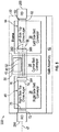
- Figure 3 is a flow diagram of an example method 100 for customizing or modifying a draper platform.
- the gripper platform may be customized modified based upon current crop conditions. By adapting to different crop conditions, the loss of crop or damage to the crop being harvested may be reduced by providing an appropriate degree of crop driving aggressiveness over the conveyor drum 48.
- method 100 is described in the context of modifying draper platform 30, it should be appreciated that method 100 may be carried out with any of the draper platform described hereafter or with any other similar draper platforms.
- a first top cross auger and a second top cross auger are supported in a spaced apart relationship above conveyor belts on a draper platform for a combine.
- left side top cross auger 44 and right side top cross auger 46 are supported in a spaced apart relationship above conveyor belts 36 and 38.
- the inner ends of augers 44, 46 are supported by respective journal structures.
- the chosen configuration for draper platform 30 may omit central roller baffle 80.
- a central roller baffle may be removably mounted between the two top cross augers above a conveyor drum.
- central roller baffle 80 is removably mounted between cross augers 44, 46 above conveyor drum 48.
- central roller baffle 80 may be removably connected to one or both of the inner ends of such cross augers 44, 46.
- one end of central roller baffle 80 may be removably connected to an inner end of one of augers 44, 46 for the transmission of torque while the other end is supported, but does not transmit torque.
- both ends of the central roller baffle 80 are removably connected to the inner ends of augers 44, 46 for the transmission of torque. In yet other implementations, both ends of central roller baffle 80 are axially spaced from the inner ends of augers 44, 46 and driven by a separate rotary drive.
- FIG 4 is a schematic diagram illustrating portions of an example draper platform 230 for use in a combine harvester.
- Draper platform 230 is similar to be draper platform 30 described above with respect to Figure 2 , with the removably mounted central roller baffle 80, except that that draper platform 230 is illustrated as specifically additionally comprising torque coupler 284, bearing coupler 286 and rotary drives 288, 290.
- Those remaining components or structures of draper platform 230 which correspond to structures or components of draper platform 30 are numbered similarly.
- Torque coupler 284 comprises an interface between the inner end 74 of auger 46 and the outer end of central roller baffle 80. Torque coupler 284 transmits torque or rotational movement from auger 46 to central roller baffle 80.
- torque coupler 284 may comprise a threaded shaft extending from one of auger 46 and baffle 80 and a threaded socket extending from the other of auger 46 and baffle 80, wherein the threaded socket receives the threaded shaft such that rotation of auger 46 tightens the threaded connection between the two members.
- torque coupler 284 may comprise other torque coupling arrangements, such as a gear train, a chain and sprocket arrangement, a belt and pulley arrangement or a noncircular shaft and a noncircular bore providing a keyed relationship for the transmission of torque.
- Bearing coupler 286 comprises an interface between the inner end 64 of auger 44 and the outer end of central roller baffle 80. Bearing coupler 286 facilitates relative rotation of auger 44 with respect to central roller baffle 80. In one implementation, bearing coupler 286 may comprise a rotational bearing between auger 44 and baffle 80. In some implementations, bearing coupler 286 may be omitted.
- Rotary drives 288, 290 comprise mechanism by which augers 44 and 46 are rotationally driven about axis be seven.
- rotary drive 288 drives left side top cross auger 44 while rotary drive 290 drives right side top cross auger 46.
- each of such drive 288, 290 has a separate independent source of torque, such as a separate hydraulic motor, electric motor or the like.
- drive 288, 290 are powered by a same torque source, such as an internal combustion engine or a single hydraulic or electric motor which is connected to each of the rotary drive 280, 290 by a distinct transmission.
- FIG. 5 schematically illustrates portions of another example draper platform 330 for use in a combine harvester.
- Draper platform 330 is similar to be draper platform 230 except that that draper platform 330 is illustrated as comprising torque coupler 384 and bearing coupler 386 in place of torque coupler 284 and bearing coupler 286.
- Those remaining components or structures of draper platform 330 which correspond to structures or components of draper platform 230 are numbered similarly.
- Torque coupler 384 and bearing coupler 386 rotationally support central roller baffle 84 rotation about a rotational axis 292 that is offset from axis 47 about which augers 44, 46 are rotatably driven. Similar to torque coupler 284, torque coupler 384 comprises an interface between the inner end 74 of auger 46 and the outer end of central roller baffle 80. Torque coupler 384 transmits torque or rotational movement from auger 46, about axis 47, to central roller baffle 80 for rotation about axis 292.
- torque coupler 384 comprises a gear train for transmitting torque from one axis to another axis.
- torque of 34 may comprise a chain and sprocket arrangement or a belt and pulley arrangement for transmitting torque from one axis to another axis.
- Bearing coupler 386 comprises an interface between the inner end 64 of auger 44 and the outer end of central roller baffle 80. Bearing coupler 386 supports baffle 80 for rotation about axis 292 and relative to the rotation of auger 44 about axis 47. In one implementation, bearing coupler 286 may comprise a rotational bearing between auger 44 and baffle 80 or between roller baffle 80 and journal support 66.
- FIG. 6 schematically illustrates portions of another example draper platform 430 for use in a combine harvester.
- Draper platform 430 is similar to be draper platform 30 except that that draper platform 430 is illustrated as comprising central roller baffle journal supports 484, 486 and rotary drive 489. Those remaining components or structures of draper platform 430 which correspond to structures or components of draper platform 30 are numbered similarly.
- Journal supports 484 and 486 comprise structures supported by frame 32 that rotationally support central roller baffle 80 for rotation about axis 292. Journal supports 484 and 46 are spaced from the inner ends of augers 44, 46 as well as their respective journal supports 286 and 284.
- journal supports 44 can may comprise structures that include roller bearings, bushings and/or other structures that facilitate rotation of baffle 80.
- journal supports 484 and 486 may alternatively rotationally support central roller baffle 80 about the same axis 47 about which augers 484 and 486 rotate, but where top cross augers 44 and 46 are spaced from the inner ends of augers 44, 46 as well as their respective journal supports 286 and 284.
- Rotary drive 489 comprises a mechanism operably coupled to central roller baffle 80, such as through or across one of journal supports 484, 486, so as to supply torque and rotationally drive central roller baffle 80.
- rotary drive 489 is synchronized with rotary drive 288 and 290.
- rotary drive 489 rotates baffle 80 at a speed distinct from that of augers 44, 46.
- rotary drive 489 utilizes a separate source of power than that of rotary drive 288, 290, such as a separate hydraulic motor, electric motor or the like.
- rotary drive 489 utilizes same source of torque as rotary drive 288, 290, but transmits such torque through a separate transmission to baffle 80.
- Figures 7 and 8 are front views schematically illustrating portions of another example draper platform 530.
- Figures 7 and 8 omit knife assembly 42 which extends along the front edge of belt conveyors 34, 36 and 38.
- knife assembly 42 flexes with the repositioning of belt conveyors 36 and 38.
- Draper platform 530 is similar to draper platform 230 described above except that central roller baffle 80 is coupled to and between augers 44 and 46 by universal joints 594A, 594B (collectively referred to as universal joints 594).
- Universal joint 594A connects central roller baffle 80 to right side top cross auger 46, either directly or indirectly via journal support 76.
- Universal joint 594B connects central roller baffle 82 left side top cross auger 44, either directly or indirectly via journal support 66.
- journal supports 288 and 290 also comprise universal joints.
- Universal joints 594 may further assist in maintaining augers 44 and 46 at angles that are aligned with a depth of the crop mat residing on belts 36 and 38. For example, as the height or thickness of the crop mat residing on belt 36 increases, top cross auger 44 may pivot in an upward direction. As a height or thickness of the crop mat residing on belt 36 decreases, top cross auger 44 may pivot in a downward direction.
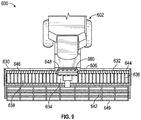
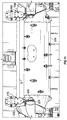
- Figures 9-11 illustrate portions of an example combine 600 comprising an example draper platform 630 having a removable central roller baffle.
- Figure 10 illustrates draper platform 630 without the gathering reels 649 shown in Figure 9 .
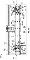
- Figure 11 is a top view of portions of draper platform 630 with the central roller baffle 680 removed.
- combine 600 comprises a main drive unit 602 that supports draper platform 630 and moves or carries draper platform 630 across a field during harvesting.
- Main drive unit 602 comprises a feeder or feeder housing 606 which conveys crops gathered by head 630 to internal mechanisms within main unit 602 which further separate and clean selected portions of the crop, such as grain, from the accompanying biomass material, such as husk, chaff and the like.
- main drive unit 602 includes straw walkers or a rotary threshing mechanism with rearwardly located chafers or sieves for separating out grain.
- the cleaned crop or grain is conveyed to a holding tank for subsequent discharge.
- the non-grain portions or biomass are discharged at a rear of the combine 600.
- the example draper platform 630 generally comprises frame 632, center belt conveyor 634, left side belt conveyor 636, right side belt conveyor 638, reciprocating knife assembly 642, gathering reels 643, left side top cross auger 644, right side top cross auger 646, conveyor drum 648 and central roller baffle 680 (shown in Figure 9 and 10 ).
- Frame 632 comprises an arrangement of panels, beams, brackets and the like supporting the remaining components of platform 632.
- Frame 632 is configured to be mounted or coupled to a feeder house of a combine in a permanent or removable fashion.
- Frame 632 includes a rear center opening 650 through which crop may be fed to the feeder house 606.
- Center belt conveyor 634 comprises an endless conveyor belt situated directly in front of center opening 650 between left side conveyor belt 636 and right side conveyor belt 538, behind knife assembly 642.
- Center conveyor belt 634 is operably coupled to a source of torque, a rotary drive, that drives center belt conveyor 634 rollers or other support structures so as to carry or convey crop material cut by knife assembly 642 in a rearward direction through opening 650 to the feeder house 606 (shown in Figure 9 )) of the combine 600.
- Left side conveyor belt 636 extends on the left side of center belt conveyor 634 (as seen from behind draper platform 630).
- Left side conveyor belt 636 comprises an endless web or conveyor belt operably coupled to a source of torque or rotary drive so as to carry the crop material cut by knife assembly 642 toward center belt conveyor 634.
- Right side conveyor belt 638 extends on the right side of center belt conveyor 634 (as seen from behind draper platform 630).
- Right side conveyor belt 638 comprises an endless web or conveyor belt operably coupled to a source of torque or rotary drive so as to carry the crop material cut by knife assembly 642 toward center belt conveyor 634.
- Knife assembly 642 comprises at least one elongate reciprocating knife assembly extending along a front edge of platform 630. Knife assembly 642 cuts or severs the crop from its growing medium. In one of limitation, knife assembly 642 comprises a single knife assembly extending across the entire front of platform 630. In other implementations, knife assembly 642 may comprise multiple subsections or sub knife assemblies that collectively extend across the front of platform 630. One example of a knife assembly 642 may comprise a cutter bar and knife guards that guide a reciprocating knife or knife sections.
- Gathering reels 643 are rotatably supported by frame 632 over knife assembly 642. Gathering reels 643 gather and direct the crop towards knife assembly 642 and onto conveyors 634, 636 and 638.
- Left side top cross auger 644 comprises an auger rotatably supported proximate a rear of frame 632 above left side conveyor 636.
- Left side top cross auger 644 is located on a left side (as seen from behind platform 630) of center belt conveyor 634.
- Left side top cross auger 644 has opposite end portions that are journaled.
- Left side top cross auger 644 has an outer end 660 supported by a journal support 662 and an inner journaled end 664 rotatably supported by journal support 666.
- Journal supports 662 and 666 rotationally support ends 660 and 664 of left side top cross auger, respectively.
- Journal supports 662 and 666 may comprise bearings that rotationally support a shaft of left side top cross auger relative to frame 632 above left side conveyor 636.
- Right side top cross auger 646 comprises an auger rotatably supported proximate a rear of frame 632 above right side conveyor 638.
- Left side top cross auger 644 and right side top cross auger 646 are coaxial, configured to be rotatably driven about a single horizontal axis 647.
- Right side top cross auger 646 is located on a right side (as seen from behind platform 630) of center belt conveyor 634.
- Right side top cross auger 646 has opposite end portions that are journaled.
- Right side top cross auger 646 has an outer end 670 supported by a journal support 672 and an inner journaled end 674 rotatably supported by journal support 676.
- Journal supports 672 and 676 rotationally support ends 670 and 674 of right side top cross auger, respectively.
- Journal supports 672 and 676 may comprise bearings that rotationally support a shaft of right side top cross auger relative to frame 632 above left side conveyor 636.
- journal supports 662, 666, 672, 676 are shown in Figures 20 and 21 .
- journal support 676 (shown in Figure 20 ) and journal support 666 (shown in Figure 21 ), which are similar to journal supports 662 and 672, comprise roller bearings 677 captured between bearing races, first bearing race 679 secured to a shaft of the respective auger 644, 646 and a second race 681 secured to a support 683 extending from frame 632.
- journal supports 662, 666, 672, 676 may have other configurations.
- Conveyor drum 648 comprises a drum rotatably supported above center belt conveyor 634.
- Conveyor drum 648 is operably coupled to a source of torque, a rotary drive (not shown) so as to be rotatably driven about a horizontal axis, parallel to the axis 647 about which augers 644 and 646 are rotatably driven.
- Conveyor drum 648 may include crop engaging elements, such as tines, baffles or the like that cooperate with center belt conveyor 634 to move and direct cut crop through opening 650 to the feeder house of the combine.
- conveyor drum 648 is rotatably driven about an axis rearwardly offset from axis 647.
- journal supports 666 and 676 support ends 664 and 674, respectively, at spaced locations, forming a space or gap G therebetween.
- the gap G extends directly above conveyor drum 648 and directly above center belt conveyor 634.
- the gap G has a length (in a direction parallel to axis 647) sufficient to receive an elongate central roller baffle.
- the length of gap G is at least 2 feet.
- Journal supports 666 and 676 independently support the ends of augers 644 and 646 to facilitate the use of platform 630 with the formed gap G and without any intermediate central roller baffles to accommodate certain crop conditions.
- journal supports 666 and 676 are illustrated at the extreme inner ends of augers 644 and 646, respectively, in other implementations, journal supports 666 and 676 may be located at and support intermediate portions of augers 644 and 646, wherein the extreme inner ends are cantilevered, but are still spaced from one another by gap G.
- Central roller baffle 680 is similar to central roller baffle 80 described above.
- Central roller baffle 680 includes at least one exterior crop driver 682.
- Crop driver 682 comprises at least one surface radially or otherwise outwardly projecting in a direction away from the rotational axis of baffle 680 so as to engage and drive crop material towards opening 650 when being rotatably driven.
- crop driver 682 may comprise a series of fingers or tines.
- crop driver 682 may comprise a series of elongated baffle plates facing in directions tangent to the rotational axis of central roller baffle 680 extending parallel to or along the rotational axis of central roller baffle 680.
- central roller baffle 680 may comprise a cylindrical structure or tube from which such baffle plates project or extend.
- central roller baffle 680 may comprise a structure wherein multiple baffle plates intersect one another along an intersection line coincident with the rotational axis of central roller baffle 680.
- central roller baffle 680 may comprise a noncircular cross-sectional shape such as a polygonal shape or an oval cross-sectional shape.
- central roller baffle 680 may have an asymmetrical cross-sectional shape, wherein the exterior of central roller baffle 680 comprises bulges and/or depressions that, similar to paddles, drive and engage crop.
- central roller baffle 680 may have other configurations.
- crop driver 682 may be integrally formed as a single unitary body.
- crop driver 682 may comprise a square or rectangular tube, and elliptical tube or the like.
- Crop primary two may comprise fixed tines, plates, baffles or other projections for driving crop.
- crop driver 682 may be releasably or removably supported by a central support of central roller baffle 680.
- crop driver 682 may comprise at least one plate which is removably mountable to the exterior of the central support portion of roller baffle 680.
- differently configured plates may be interchangeably mounted to the central support portion to provide central roller baffle 680 with different levels of aggressiveness with respect to driving a crop.
- multiple sets of different plates offering different customized levels of crop driving aggressiveness may be interchangeably mounted to the central support of baffle 680 with the same mounting structures.
- the at least one plate which is removably mounted to the central support of central roller baffle 680 may be configured such that the orientation in which such plates are mounted to the central support portion impacts the level of aggressiveness central roller baffle 680 has with respect to driving a crop.
- the same plate may offer a first level of crop driving aggressiveness when in a first orientation and may offer a second greater level of crop aggressiveness when mounted to the central support portion of baffle 680 in a second orientation, such as 180° from the first orientation.
- draper platform 630 offers a user the ability to change the configuration of draper platform 630 in multiple fashions.
- a user may remove the entire central roller baffle 680.
- user may insert first central roller baffle6 80 having a first crop driver 82 offering a first degree of crop driving aggressiveness. If crop conditions change once again, the user may remove the first central roller baffle 680 and insert a second central roller baffle having a second crop driver 682 offering a second degree of crop driving aggressiveness.
- the user may leave the central roller baffle 680 in place, but instead remove the current crop driver 682 and mount a different crop driver 682 having a different degree of crop driving aggressiveness.
- FIG 12 is a sectional view illustrating an example central roller baffle 780 removably mounted between augers 646 and 644 of draper platform 630 by example couplers 784 and 786.
- central roller baffle 780 comprises a reconfigurable roller baffle comprising a rotatable support 800 and a removable or exchangeable crop driver 802 (schematically shown).
- central roller baffle 780 may comprise a roller baffle having crop drivers that are permanently affixed to or integrally formed as a single unitary body with a rotatable support 800.
- Rotatable support 800 serves as a central support structure or portion for roller baffle 780.
- rotatable support 800 comprises an elongate cylinder extending along axis 647 having opposite axial ends coupled to augers 646 and 644 by couplers 784 and 786, respectively.
- Rotatable support 800 has an outer surface comprising a plurality of mounting structures 806 by which crop drivers 802 may be removably mounted.
- rotatable support 800 comprise threaded bores for receiving fasteners that also extend through portions of crop driver 802.
- rotatable support 800 may have other non-circular cross-sectional shapes and may utilize an alternative mounting structures or mounting structures having a different arrangement along support 800.
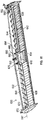
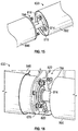
- FIGS 13-16 illustrate the removable mounting of support 800 to augers 646.
- Figures 13-16 illustrate the mounting of torque coupler 784 between augers 646 and support 800.
- Torque coupler 784 is an example of torque coupler 284 described above. Torque coupler 784 facilitates the transmission of torque rotational movement from augers 646 two support 800 and roller baffle 780.
- FIG 13 illustrates the inner end of augers 646 following removal of a protective cap 808 (shown in Figure 11 ) to expose an externally threaded shaft 810 over which a nut 812 is positioned.
- Figure 14 illustrates the removal of nut 812 and the mounting of flanged shaft 814.
- flanged shaft 814 comprise an internally threaded bore 815 (shown in Figure 21 ) which threadably engages external cutter at the threads of shaft 810.
- the threads are configured such that the crop driving rotation of auger 646 relative to shaft 814 tightens the threaded coupling (further screws or threads shaft 810 into threaded bore 815 until no further rotation is permitted).
- shaft 814 may be secured to the axial end of auger 646 in other manners.
- flanged shaft 814 is further fastened to the the outer axial end of support 800 by fasteners 806. In other implementations, flanged shaft 814 may be secured to support 800 in other fashions.
- brackets 820 are further fastened to the axial end of auger 646. As will be described hereafter, brackets 820 facilitate the mounting of wrap guards.
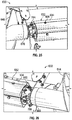
- FIGs 17 and 18 illustrate one example of the mounting of bearing coupler 786 to the outer end of support 800.
- Bearing coupler 786 is one example of bearing coupler 286 described above.
- Bearing coupler 286 facilitates relative rotation of auger 644 with respect to central roller baffle support 80.
- FIG 17 illustrates an example bearing coupler 786 prior to being mounted to support 800.
- bearing coupler 786 comprises bearing 824 and brackets 826.
- Bearing 824 comprises a center portion 828 having a non-circular central bore 830 which is to be keyed onto a corresponding non-circular shaft 832 of support 800.
- Center portion 828 is supported by internal bearings, such as roller bearings or ball bearings 829 (shown in Figure 22 ), relative to an outer ring 834.
- Brackets 826 are coupled to outer ring 834 by an intermediate plate 836. Brackets 826 have mounting portions 838 for fastening to an axial end of auger 644. In the example illustrated, brackets 826 further comprise mounting portions 840 for securing a wrap guard.
- Figures 19-21 illustrate the completed assembly of support 802 couplers 784, 786 between augers 644 and 646.
- wrap guards 844 and 846 are mounted to brackets 826 and 820 (shown in Figure 15 ).
- Wrap guard 844 covers and overlaps brackets 826 and is partially nested within the axial end of support 800.
- wrap guard 866 covers and overlaps brackets 820 and is partially nested within the axial end of support 800.
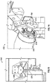
- FIGs 22 and 23 illustrate an example crop driver 902 removably mounted on support 800 of central roller baffle 780 of draper platform 630.
- crop driver 902 are in the form of four angled plates 904 which, when mounted about the port 800 by fasteners 906, provide central roller baffle 780 with a polygonal outer profile or cross-sectional shape.
- plates 904 provide baffle 780 with a square outer profile or cross-sectional shape.
- central roller baffle 780 may be provided with other auto profiles or cross-sectional shapes with other combinations of plates.
- the outer profile of baffle 780 may be provided with a fewer or lesser number of such plates, with plates having other shapes or with other non-plate structures.
- crop driver 902 may be secured to support 800 and other fashions.
- crop driver 902 may be secured using a tongue and groove arrangement, wherein one of support 800 and the structures that form crop driver 902 has a tongue and the other of support 800 and the structures that form crop driver 902 has a corresponding groove that slidably receives the tongue.
- FIG 24 is a sectional view illustrating crop driver 922 removably mounted to support 800.
- Crop driver 922 is similar to crop driver 902 except that crop driver 922 additionally comprises baffles 924.
- Baffles 924 comprise elongate plates having openings that align with openings of plates 904 such that baffles 924 may be secured to plates 904 and support 800 with the same fasteners 906.
- baffles 924 extend along an entire axial length of support 800.
- baffles 924 may comprise multiple individual baffles spaced along the axial length of support 900.
- Baffles 924 project outwardly beyond the corners of the outer profile formed by plates 904 to provide for more aggressive driving of the crop. In crop conditions warranting a more aggressive driving of crops, a user may remove faster 906 and additionally mount baffles 924 in place. In crop conditions warranting a less aggressive driving of crops, a user may remove baffles 924 as needed.
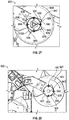
- FIGs 25-29 illustrate crop driver 932 removably mounted to support 800 of draper platform 630. Similar to crop driver 902, crop driver 932 is formed by multiple plates 934 removably mounted to the exterior of support 800 by fasteners 906. Unlike crop driver 902, crop driver 902 has an outer profile or cross-sectional shape that is asymmetric with respect to the rotational axis of support 800. As shown by Figure 26 , crop driver 932 has a plurality of outwardly projecting protuberances 936 with each protuberance having a flatter, less sharp or more gradually sloping side 938 and a sharper or steeper side 940.
- FIGs 28 and 29 illustrate draper platform 630 with crop driver 933 the slightly different configuration of plates 934.
- Each of the plates 934 have mounting openings that align with corresponding mounting openings in support 800 regardless of the orientation of such plates with respect to support 800.
- each of plates 934 may be mounted to support 800, using the provided mounting holes such that the flatter side 938 becomes the leading edge, facing in a clockwise direction with respect axis 947 as seen in Figure 28 .
- each of plates 934 may be mounted to support 800 using the provided mounting holes such that the sharper side 940 becomes a leading-edge, facing in the clockwise direction with respect axis 947 as seen in Figure 29 .
- the same edges of plates 934 may face either leftward or rightward while being mounted on support 800.
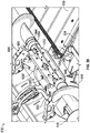
- FIG 30 illustrates central roller baffle 1080 removably mounted between augers 644 and 646 of draper support 630, in place of an of the above described roller baffles or other roller baffles.
- Central roller baffle 1080 is similar to central roller baffle 780 except that central roller baffle 1080 comprises an arrangement of panels that are coupled to augur 644 and 646 by couplers 784 and 786 described above.
- central roller baffle 1080 comprises a primary panel 1050, secondary panels 1052 (only one of which is shown) an end panels 1054 (one of which is shown).
- Primary panel 1050 extends along a majority the length of baffle 1080.
- Secondary panels 1052 extend from opposite sides or faces of1050. The example illustrated, secondary panels 1052 perpendicularly extend from the opposite side faces of primary panel 1050, opposite to one another, providing central roller baffle 1080 with a "+" shape. In the example illustrated, secondary panels 1052 are fastened to primary panel 1050. In other implementations, secondary panels 1052 may be welded or bonded to primary panel 1050. Some implementations, secondary panels 1052 may be integrally formed as a single unitary body with primary panel 1050. In the example illustrated, each of panels 1050, 1052 comprises a band edge 1056 further assist in gathering and driving crop.
- End panels 1054 extended opposite axial ends of panels 1050, 1052. End panels 1054 comprise circular flat plates fastened, bonded or welded to the edges of the opposite ends of panels 1050, 1052. And panels 1054 facilitates securement of couplers 784, 786, described above.
- central roller baffle 1080 illustrated as having four blades angry spaced from one another by 90° about the rotational axis of baffle 1080 other central roller baffles 1080 may alternatively include other arrangements and numbers of blades.
- another roller baffle 1080 may include three such blades angry spaced 180° apart from one another.
- Another roller baffle 1080 may include six blades angry spaced 30° apart from one another.
- Draper platform 630 facilitates the removal of one central roller baffle 1080 having a first arrangement of blades and replacement with another central roller baffle 1080 having a different arrangement or number of blades.
- draper platform 630 further facilitates the replacement of roller baffle 1080 with any of the above described roller baffles, depending upon the degree of aggressiveness desired for the roller baffle.
- FIG 31 is a side view of another example roller baffle 1180.
- Roller baffle 1180 is similar to roller baffle 1080 except the roller baffle 1180 additionally comprises conical wrap guard extensions 1060.
- Wrap guard extensions 1060 extend from wrap guards 844 and 846, projecting over the axial ends of panels 1050, 1052. Wrap guard extensions 1060 further assist in inhibiting the laughing or collection of crop material about baffle 1180 as baffle 1180 is being rotationally driven.
Landscapes
- Life Sciences & Earth Sciences (AREA)
- Environmental Sciences (AREA)
- Harvester Elements (AREA)
- Outside Dividers And Delivering Mechanisms For Harvesters (AREA)
- Threshing Machine Elements (AREA)
Applications Claiming Priority (1)
| Application Number | Priority Date | Filing Date | Title |
|---|---|---|---|
| US15/663,695 US10477767B2 (en) | 2017-07-28 | 2017-07-28 | Draper platform with removable central roller baffle |
Publications (3)
| Publication Number | Publication Date |
|---|---|
| EP3434096A2 true EP3434096A2 (de) | 2019-01-30 |
| EP3434096A3 EP3434096A3 (de) | 2019-05-22 |
| EP3434096B1 EP3434096B1 (de) | 2021-06-23 |
Family
ID=63077764
Family Applications (1)
| Application Number | Title | Priority Date | Filing Date |
|---|---|---|---|
| EP18185775.6A Active EP3434096B1 (de) | 2017-07-28 | 2018-07-26 | Draper-plattform mit entfernbarer zentraler walzenablenkplatte |
Country Status (2)
| Country | Link |
|---|---|
| US (1) | US10477767B2 (de) |
| EP (1) | EP3434096B1 (de) |
Cited By (1)
| Publication number | Priority date | Publication date | Assignee | Title |
|---|---|---|---|---|
| EP3750393A1 (de) * | 2019-06-13 | 2020-12-16 | MacDon Industries Ltd. | Erntevorsatz mit drei abschnitten mit schneidwerken und oberer querförderschnecke |
Families Citing this family (5)
| Publication number | Priority date | Publication date | Assignee | Title |
|---|---|---|---|---|
| DE102017113775A1 (de) * | 2017-06-21 | 2018-12-27 | Carl Geringhoff Gmbh & Co. Kg | Draper-Schneidwerk mit mehrteiliger Förderschnecke |
| US10806081B2 (en) * | 2017-09-14 | 2020-10-20 | Deere & Company | Crop deflector for a harvesting head |
| CA3033127C (en) * | 2018-02-07 | 2022-03-15 | Ag Shield Ltd. | Cross auger mounting device for flexible harvesting header |
| US10820515B2 (en) * | 2018-06-28 | 2020-11-03 | Deere & Company | Combine header with feed assist bulky crop auger on a draper platform |
| US11160210B2 (en) * | 2019-06-13 | 2021-11-02 | Macdon Industries Ltd. | Three-section crop header with drapers and top cross auger |
Family Cites Families (22)
| Publication number | Priority date | Publication date | Assignee | Title |
|---|---|---|---|---|
| FR1415334A (fr) | 1964-12-01 | 1965-10-22 | Int Harvester Co | Andaineuse ayant une plate-forme comportant deux vis transporteuses |
| US4597510A (en) | 1982-04-26 | 1986-07-01 | Westmont, Inc. | Impeller packing machine with pre-conditioning hopper |
| US4487004A (en) | 1983-06-03 | 1984-12-11 | Kejr Melvin P | Combine harvester apparatus |
| US5005343A (en) * | 1988-06-22 | 1991-04-09 | Macdon Industries Ltd. | Header for a combine harvesting machine |
| US4956966A (en) * | 1988-06-22 | 1990-09-18 | Macdon Industries Ltd. | Header for a combine harvesting machine |
| US6564535B1 (en) | 2000-03-07 | 2003-05-20 | Agco Corporation | Drive mechanism for center gathering double augers of a crop harvester |
| US6640527B2 (en) | 2001-12-18 | 2003-11-04 | New Holland North America, Inc. | Center feed finger adjustment mechanism for header |
| US7587885B2 (en) | 2007-06-04 | 2009-09-15 | Claas Selbstfahrende Emtemaschinen Gmbh | Central auger crop feed system for a harvester |
| US8281561B2 (en) | 2010-08-17 | 2012-10-09 | Deere & Company | Flexible draper belt drive for an agricultural harvesting machine |
| US7971420B1 (en) * | 2010-08-31 | 2011-07-05 | Deere & Company | Draper platform suspension |
| US8166738B1 (en) * | 2011-05-04 | 2012-05-01 | Deere & Company | Combine header with crop compression rollers |
| US9258944B2 (en) * | 2011-06-06 | 2016-02-16 | Jose Luis Allochis | Flexible platform joined to a conveyor belt for a combine harvester |
| US8695315B2 (en) | 2012-08-09 | 2014-04-15 | Deere & Company | Draper header with pivoting side draper conveyors |
| US9078396B2 (en) | 2013-02-28 | 2015-07-14 | Deere & Company | Draper belt platform with additional conveyor in transition area |
| US9750190B2 (en) * | 2013-12-11 | 2017-09-05 | Deere & Company | Harvesting head upper belt conveyor compressing crop against a center belt conveyor |
| US20150195992A1 (en) | 2014-01-13 | 2015-07-16 | Deere & Company | Draper Roller with Active Retracting Cleat Crop Stripper |
| US9516816B2 (en) * | 2015-04-07 | 2016-12-13 | Jose Luis Allochis | Multiple drums conveyor for an agricultural platform |
| US20160360699A1 (en) * | 2015-06-10 | 2016-12-15 | Jose Luis Allochis | Conveyor belt tensing apparatus for a harvesting header |
| US9578806B2 (en) * | 2015-06-12 | 2017-02-28 | Cnh Industrial America Llc | Agricultural harvester header with retracting paddles for conveying crop material |
| US9820434B2 (en) * | 2016-01-27 | 2017-11-21 | Ag Shield Ltd. | Angled stripper for a cross auger on a crop harvesting header |
| DE102016115589A1 (de) * | 2016-08-23 | 2018-03-01 | Claas Selbstfahrende Erntemaschinen Gmbh | Bandschneidwerk |
| US10321626B2 (en) * | 2016-08-26 | 2019-06-18 | Cnh Industrial America Llc | Lightweight stalk roll knife |
-
2017
- 2017-07-28 US US15/663,695 patent/US10477767B2/en active Active
-
2018
- 2018-07-26 EP EP18185775.6A patent/EP3434096B1/de active Active
Non-Patent Citations (1)
| Title |
|---|
| None |
Cited By (1)
| Publication number | Priority date | Publication date | Assignee | Title |
|---|---|---|---|---|
| EP3750393A1 (de) * | 2019-06-13 | 2020-12-16 | MacDon Industries Ltd. | Erntevorsatz mit drei abschnitten mit schneidwerken und oberer querförderschnecke |
Also Published As
| Publication number | Publication date |
|---|---|
| US20190029180A1 (en) | 2019-01-31 |
| US10477767B2 (en) | 2019-11-19 |
| EP3434096B1 (de) | 2021-06-23 |
| EP3434096A3 (de) | 2019-05-22 |
| BR102018015350A2 (pt) | 2019-03-19 |
Similar Documents
| Publication | Publication Date | Title |
|---|---|---|
| EP3434098B1 (de) | Streckplattform mit konfigurierbarer zentraler ablenkwalze | |
| EP3434096B1 (de) | Draper-plattform mit entfernbarer zentraler walzenablenkplatte | |
| EP2995188B1 (de) | Antriebsanordnung für einen maispflückkopf einer landwirtschaftlichen erntemaschine | |
| US8490371B2 (en) | Modular electric disc cutterbar and controller | |
| CN104996087B (zh) | 具有独立子系统驱动器的用于农业收割机的收割台 | |
| EP3153006B1 (de) | Nicht-reihenempfindlicher dreschmaisplfücker | |
| CA2473183C (en) | Crop gathering device with conveyor belt assembly | |
| US12453311B2 (en) | Electric row unit drive system for corn header of combine harvester | |
| US20120042618A1 (en) | Tilting Crop Stalk Chopper | |
| US20160324070A1 (en) | Non-Row Sensitive Forage Harvester Header | |
| US20110154793A1 (en) | Forage chopper header for harvesting both standing and down crop material | |
| JP2008220256A (ja) | コンバイン | |
| BR102018015349B1 (pt) | Plataforma de lona | |
| BR102018015350B1 (pt) | Plataforma de lona para montagem em uma câmara de alimentação de uma combinada agrícola | |
| JP2000004645A (ja) | コンバイン | |
| US12279556B2 (en) | Dual variable feeder drive for agricultural vehicle | |
| CN205284186U (zh) | 不对行双转筒青贮饲料收获机 | |
| CN222982015U (zh) | 切碎装置及联合收割机 | |
| CN207354909U (zh) | 一种用于收获机的直切式割台 |
Legal Events
| Date | Code | Title | Description |
|---|---|---|---|
| PUAI | Public reference made under article 153(3) epc to a published international application that has entered the european phase |
Free format text: ORIGINAL CODE: 0009012 |
|
| STAA | Information on the status of an ep patent application or granted ep patent |
Free format text: STATUS: THE APPLICATION HAS BEEN PUBLISHED |
|
| AK | Designated contracting states |
Kind code of ref document: A2 Designated state(s): AL AT BE BG CH CY CZ DE DK EE ES FI FR GB GR HR HU IE IS IT LI LT LU LV MC MK MT NL NO PL PT RO RS SE SI SK SM TR |
|
| AX | Request for extension of the european patent |
Extension state: BA ME |
|
| PUAL | Search report despatched |
Free format text: ORIGINAL CODE: 0009013 |
|
| AK | Designated contracting states |
Kind code of ref document: A3 Designated state(s): AL AT BE BG CH CY CZ DE DK EE ES FI FR GB GR HR HU IE IS IT LI LT LU LV MC MK MT NL NO PL PT RO RS SE SI SK SM TR |
|
| AX | Request for extension of the european patent |
Extension state: BA ME |
|
| RIC1 | Information provided on ipc code assigned before grant |
Ipc: A01D 61/00 20060101ALI20190415BHEP Ipc: A01D 41/14 20060101AFI20190415BHEP |
|
| STAA | Information on the status of an ep patent application or granted ep patent |
Free format text: STATUS: REQUEST FOR EXAMINATION WAS MADE |
|
| 17P | Request for examination filed |
Effective date: 20191122 |
|
| RBV | Designated contracting states (corrected) |
Designated state(s): AL AT BE BG CH CY CZ DE DK EE ES FI FR GB GR HR HU IE IS IT LI LT LU LV MC MK MT NL NO PL PT RO RS SE SI SK SM TR |
|
| GRAP | Despatch of communication of intention to grant a patent |
Free format text: ORIGINAL CODE: EPIDOSNIGR1 |
|
| STAA | Information on the status of an ep patent application or granted ep patent |
Free format text: STATUS: GRANT OF PATENT IS INTENDED |
|
| INTG | Intention to grant announced |
Effective date: 20210215 |
|
| GRAS | Grant fee paid |
Free format text: ORIGINAL CODE: EPIDOSNIGR3 |
|
| GRAA | (expected) grant |
Free format text: ORIGINAL CODE: 0009210 |
|
| STAA | Information on the status of an ep patent application or granted ep patent |
Free format text: STATUS: THE PATENT HAS BEEN GRANTED |
|
| AK | Designated contracting states |
Kind code of ref document: B1 Designated state(s): AL AT BE BG CH CY CZ DE DK EE ES FI FR GB GR HR HU IE IS IT LI LT LU LV MC MK MT NL NO PL PT RO RS SE SI SK SM TR |
|
| REG | Reference to a national code |
Ref country code: GB Ref legal event code: FG4D |
|
| REG | Reference to a national code |
Ref country code: CH Ref legal event code: EP |
|
| REG | Reference to a national code |
Ref country code: DE Ref legal event code: R096 Ref document number: 602018018884 Country of ref document: DE Ref country code: AT Ref legal event code: REF Ref document number: 1403443 Country of ref document: AT Kind code of ref document: T Effective date: 20210715 |
|
| REG | Reference to a national code |
Ref country code: IE Ref legal event code: FG4D |
|
| REG | Reference to a national code |
Ref country code: LT Ref legal event code: MG9D |
|
| PG25 | Lapsed in a contracting state [announced via postgrant information from national office to epo] |
Ref country code: HR Free format text: LAPSE BECAUSE OF FAILURE TO SUBMIT A TRANSLATION OF THE DESCRIPTION OR TO PAY THE FEE WITHIN THE PRESCRIBED TIME-LIMIT Effective date: 20210623 Ref country code: LT Free format text: LAPSE BECAUSE OF FAILURE TO SUBMIT A TRANSLATION OF THE DESCRIPTION OR TO PAY THE FEE WITHIN THE PRESCRIBED TIME-LIMIT Effective date: 20210623 Ref country code: FI Free format text: LAPSE BECAUSE OF FAILURE TO SUBMIT A TRANSLATION OF THE DESCRIPTION OR TO PAY THE FEE WITHIN THE PRESCRIBED TIME-LIMIT Effective date: 20210623 Ref country code: BG Free format text: LAPSE BECAUSE OF FAILURE TO SUBMIT A TRANSLATION OF THE DESCRIPTION OR TO PAY THE FEE WITHIN THE PRESCRIBED TIME-LIMIT Effective date: 20210923 |
|
| REG | Reference to a national code |
Ref country code: AT Ref legal event code: MK05 Ref document number: 1403443 Country of ref document: AT Kind code of ref document: T Effective date: 20210623 |
|
| PG25 | Lapsed in a contracting state [announced via postgrant information from national office to epo] |
Ref country code: GR Free format text: LAPSE BECAUSE OF FAILURE TO SUBMIT A TRANSLATION OF THE DESCRIPTION OR TO PAY THE FEE WITHIN THE PRESCRIBED TIME-LIMIT Effective date: 20210924 Ref country code: RS Free format text: LAPSE BECAUSE OF FAILURE TO SUBMIT A TRANSLATION OF THE DESCRIPTION OR TO PAY THE FEE WITHIN THE PRESCRIBED TIME-LIMIT Effective date: 20210623 Ref country code: SE Free format text: LAPSE BECAUSE OF FAILURE TO SUBMIT A TRANSLATION OF THE DESCRIPTION OR TO PAY THE FEE WITHIN THE PRESCRIBED TIME-LIMIT Effective date: 20210623 Ref country code: LV Free format text: LAPSE BECAUSE OF FAILURE TO SUBMIT A TRANSLATION OF THE DESCRIPTION OR TO PAY THE FEE WITHIN THE PRESCRIBED TIME-LIMIT Effective date: 20210623 Ref country code: NO Free format text: LAPSE BECAUSE OF FAILURE TO SUBMIT A TRANSLATION OF THE DESCRIPTION OR TO PAY THE FEE WITHIN THE PRESCRIBED TIME-LIMIT Effective date: 20210923 |
|
| REG | Reference to a national code |
Ref country code: NL Ref legal event code: MP Effective date: 20210623 |
|
| PG25 | Lapsed in a contracting state [announced via postgrant information from national office to epo] |
Ref country code: SM Free format text: LAPSE BECAUSE OF FAILURE TO SUBMIT A TRANSLATION OF THE DESCRIPTION OR TO PAY THE FEE WITHIN THE PRESCRIBED TIME-LIMIT Effective date: 20210623 Ref country code: SK Free format text: LAPSE BECAUSE OF FAILURE TO SUBMIT A TRANSLATION OF THE DESCRIPTION OR TO PAY THE FEE WITHIN THE PRESCRIBED TIME-LIMIT Effective date: 20210623 Ref country code: ES Free format text: LAPSE BECAUSE OF FAILURE TO SUBMIT A TRANSLATION OF THE DESCRIPTION OR TO PAY THE FEE WITHIN THE PRESCRIBED TIME-LIMIT Effective date: 20210623 Ref country code: EE Free format text: LAPSE BECAUSE OF FAILURE TO SUBMIT A TRANSLATION OF THE DESCRIPTION OR TO PAY THE FEE WITHIN THE PRESCRIBED TIME-LIMIT Effective date: 20210623 Ref country code: AT Free format text: LAPSE BECAUSE OF FAILURE TO SUBMIT A TRANSLATION OF THE DESCRIPTION OR TO PAY THE FEE WITHIN THE PRESCRIBED TIME-LIMIT Effective date: 20210623 Ref country code: CZ Free format text: LAPSE BECAUSE OF FAILURE TO SUBMIT A TRANSLATION OF THE DESCRIPTION OR TO PAY THE FEE WITHIN THE PRESCRIBED TIME-LIMIT Effective date: 20210623 Ref country code: NL Free format text: LAPSE BECAUSE OF FAILURE TO SUBMIT A TRANSLATION OF THE DESCRIPTION OR TO PAY THE FEE WITHIN THE PRESCRIBED TIME-LIMIT Effective date: 20210623 Ref country code: RO Free format text: LAPSE BECAUSE OF FAILURE TO SUBMIT A TRANSLATION OF THE DESCRIPTION OR TO PAY THE FEE WITHIN THE PRESCRIBED TIME-LIMIT Effective date: 20210623 Ref country code: PT Free format text: LAPSE BECAUSE OF FAILURE TO SUBMIT A TRANSLATION OF THE DESCRIPTION OR TO PAY THE FEE WITHIN THE PRESCRIBED TIME-LIMIT Effective date: 20211025 |
|
| PG25 | Lapsed in a contracting state [announced via postgrant information from national office to epo] |
Ref country code: PL Free format text: LAPSE BECAUSE OF FAILURE TO SUBMIT A TRANSLATION OF THE DESCRIPTION OR TO PAY THE FEE WITHIN THE PRESCRIBED TIME-LIMIT Effective date: 20210623 |
|
| REG | Reference to a national code |
Ref country code: CH Ref legal event code: PL |
|
| REG | Reference to a national code |
Ref country code: DE Ref legal event code: R097 Ref document number: 602018018884 Country of ref document: DE |
|
| PG25 | Lapsed in a contracting state [announced via postgrant information from national office to epo] |
Ref country code: MC Free format text: LAPSE BECAUSE OF FAILURE TO SUBMIT A TRANSLATION OF THE DESCRIPTION OR TO PAY THE FEE WITHIN THE PRESCRIBED TIME-LIMIT Effective date: 20210623 |
|
| REG | Reference to a national code |
Ref country code: BE Ref legal event code: MM Effective date: 20210731 |
|
| PG25 | Lapsed in a contracting state [announced via postgrant information from national office to epo] |
Ref country code: LI Free format text: LAPSE BECAUSE OF NON-PAYMENT OF DUE FEES Effective date: 20210731 Ref country code: DK Free format text: LAPSE BECAUSE OF FAILURE TO SUBMIT A TRANSLATION OF THE DESCRIPTION OR TO PAY THE FEE WITHIN THE PRESCRIBED TIME-LIMIT Effective date: 20210623 Ref country code: CH Free format text: LAPSE BECAUSE OF NON-PAYMENT OF DUE FEES Effective date: 20210731 |
|
| PLBE | No opposition filed within time limit |
Free format text: ORIGINAL CODE: 0009261 |
|
| STAA | Information on the status of an ep patent application or granted ep patent |
Free format text: STATUS: NO OPPOSITION FILED WITHIN TIME LIMIT |
|
| 26N | No opposition filed |
Effective date: 20220324 |
|
| PG25 | Lapsed in a contracting state [announced via postgrant information from national office to epo] |
Ref country code: LU Free format text: LAPSE BECAUSE OF NON-PAYMENT OF DUE FEES Effective date: 20210726 Ref country code: AL Free format text: LAPSE BECAUSE OF FAILURE TO SUBMIT A TRANSLATION OF THE DESCRIPTION OR TO PAY THE FEE WITHIN THE PRESCRIBED TIME-LIMIT Effective date: 20210623 |
|
| PG25 | Lapsed in a contracting state [announced via postgrant information from national office to epo] |
Ref country code: IT Free format text: LAPSE BECAUSE OF FAILURE TO SUBMIT A TRANSLATION OF THE DESCRIPTION OR TO PAY THE FEE WITHIN THE PRESCRIBED TIME-LIMIT Effective date: 20210623 Ref country code: IE Free format text: LAPSE BECAUSE OF NON-PAYMENT OF DUE FEES Effective date: 20210726 Ref country code: FR Free format text: LAPSE BECAUSE OF NON-PAYMENT OF DUE FEES Effective date: 20210823 Ref country code: BE Free format text: LAPSE BECAUSE OF NON-PAYMENT OF DUE FEES Effective date: 20210731 |
|
| GBPC | Gb: european patent ceased through non-payment of renewal fee |
Effective date: 20220726 |
|
| PG25 | Lapsed in a contracting state [announced via postgrant information from national office to epo] |
Ref country code: GB Free format text: LAPSE BECAUSE OF NON-PAYMENT OF DUE FEES Effective date: 20220726 |
|
| PG25 | Lapsed in a contracting state [announced via postgrant information from national office to epo] |
Ref country code: CY Free format text: LAPSE BECAUSE OF FAILURE TO SUBMIT A TRANSLATION OF THE DESCRIPTION OR TO PAY THE FEE WITHIN THE PRESCRIBED TIME-LIMIT Effective date: 20210623 |
|
| PG25 | Lapsed in a contracting state [announced via postgrant information from national office to epo] |
Ref country code: HU Free format text: LAPSE BECAUSE OF FAILURE TO SUBMIT A TRANSLATION OF THE DESCRIPTION OR TO PAY THE FEE WITHIN THE PRESCRIBED TIME-LIMIT; INVALID AB INITIO Effective date: 20180726 |
|
| PG25 | Lapsed in a contracting state [announced via postgrant information from national office to epo] |
Ref country code: MK Free format text: LAPSE BECAUSE OF FAILURE TO SUBMIT A TRANSLATION OF THE DESCRIPTION OR TO PAY THE FEE WITHIN THE PRESCRIBED TIME-LIMIT Effective date: 20210623 |
|
| PG25 | Lapsed in a contracting state [announced via postgrant information from national office to epo] |
Ref country code: TR Free format text: LAPSE BECAUSE OF FAILURE TO SUBMIT A TRANSLATION OF THE DESCRIPTION OR TO PAY THE FEE WITHIN THE PRESCRIBED TIME-LIMIT Effective date: 20210623 |
|
| PG25 | Lapsed in a contracting state [announced via postgrant information from national office to epo] |
Ref country code: MT Free format text: LAPSE BECAUSE OF FAILURE TO SUBMIT A TRANSLATION OF THE DESCRIPTION OR TO PAY THE FEE WITHIN THE PRESCRIBED TIME-LIMIT Effective date: 20210623 |
|
| PGFP | Annual fee paid to national office [announced via postgrant information from national office to epo] |
Ref country code: DE Payment date: 20250620 Year of fee payment: 8 |