EP3434169A1 - Mechanisches system für distale spitze zur steuerung eines medizinischen einführrohrs, insbesondere ein endoskopeinführrohr, und ein endoskopgriff - Google Patents
Mechanisches system für distale spitze zur steuerung eines medizinischen einführrohrs, insbesondere ein endoskopeinführrohr, und ein endoskopgriff Download PDFInfo
- Publication number
- EP3434169A1 EP3434169A1 EP18185923.2A EP18185923A EP3434169A1 EP 3434169 A1 EP3434169 A1 EP 3434169A1 EP 18185923 A EP18185923 A EP 18185923A EP 3434169 A1 EP3434169 A1 EP 3434169A1
- Authority
- EP
- European Patent Office
- Prior art keywords
- pins
- lever
- guide
- insertion tube
- base
- Prior art date
- Legal status (The legal status is an assumption and is not a legal conclusion. Google has not performed a legal analysis and makes no representation as to the accuracy of the status listed.)
- Granted
Links
Images






Classifications
-
- A—HUMAN NECESSITIES
- A61—MEDICAL OR VETERINARY SCIENCE; HYGIENE
- A61B—DIAGNOSIS; SURGERY; IDENTIFICATION
- A61B1/00—Instruments for performing medical examinations of the interior of cavities or tubes of the body by visual or photographical inspection, e.g. endoscopes; Illuminating arrangements therefor
- A61B1/005—Flexible endoscopes
- A61B1/0051—Flexible endoscopes with controlled bending of insertion part
- A61B1/0052—Constructional details of control elements, e.g. handles
-
- A—HUMAN NECESSITIES
- A61—MEDICAL OR VETERINARY SCIENCE; HYGIENE
- A61B—DIAGNOSIS; SURGERY; IDENTIFICATION
- A61B1/00—Instruments for performing medical examinations of the interior of cavities or tubes of the body by visual or photographical inspection, e.g. endoscopes; Illuminating arrangements therefor
- A61B1/005—Flexible endoscopes
- A61B1/0051—Flexible endoscopes with controlled bending of insertion part
- A61B1/0057—Constructional details of force transmission elements, e.g. control wires
-
- A—HUMAN NECESSITIES
- A61—MEDICAL OR VETERINARY SCIENCE; HYGIENE
- A61M—DEVICES FOR INTRODUCING MEDIA INTO, OR ONTO, THE BODY; DEVICES FOR TRANSDUCING BODY MEDIA OR FOR TAKING MEDIA FROM THE BODY; DEVICES FOR PRODUCING OR ENDING SLEEP OR STUPOR
- A61M25/00—Catheters; Hollow probes
- A61M25/01—Introducing, guiding, advancing, emplacing or holding catheters
- A61M25/0105—Steering means as part of the catheter or advancing means; Markers for positioning
- A61M25/0133—Tip steering devices
- A61M25/0136—Handles therefor
-
- A—HUMAN NECESSITIES
- A61—MEDICAL OR VETERINARY SCIENCE; HYGIENE
- A61M—DEVICES FOR INTRODUCING MEDIA INTO, OR ONTO, THE BODY; DEVICES FOR TRANSDUCING BODY MEDIA OR FOR TAKING MEDIA FROM THE BODY; DEVICES FOR PRODUCING OR ENDING SLEEP OR STUPOR
- A61M25/00—Catheters; Hollow probes
- A61M25/01—Introducing, guiding, advancing, emplacing or holding catheters
- A61M25/0105—Steering means as part of the catheter or advancing means; Markers for positioning
- A61M25/0133—Tip steering devices
- A61M25/0147—Tip steering devices with movable mechanical means, e.g. pull wires
-
- G—PHYSICS
- G02—OPTICS
- G02B—OPTICAL ELEMENTS, SYSTEMS OR APPARATUS
- G02B23/00—Telescopes, e.g. binoculars; Periscopes; Instruments for viewing the inside of hollow bodies; Viewfinders; Optical aiming or sighting devices
- G02B23/24—Instruments or systems for viewing the inside of hollow bodies, e.g. fibrescopes
- G02B23/2476—Non-optical details, e.g. housings, mountings, supports
Definitions
- the subject of the invention is a system for controlling the movement of a flexible ending - distal tip of a medical insertion tube, especially an endoscope insertion tube and also an endoscope handle comprising this system for controlling the movement of the flexible end of medical insertion tube.
- the invention is to be used for medical devices equipped with a insertion tube for diagnostics and medical procedures, in particular for observation and operating on internal organs through natural body cavities.
- the medical devices are equipped with a movable end where the movement is performed and determined by tension cables - strands.
- Each knob is connected with the one end of appropriate tension cable and the other one end to the tip of the insertion tube.
- the first of the knobs causes the movement of the tip of the endoscope in one of the two planes, referred to as the vertical plane, i.e. up-down, the second knob move the tip in the plane perpendicular to the first defined as the horizontal plane i.e. left-right. Controlling by means of knobs is achieved by pulling and dropping the appropriate tension cables.
- Endoscopy requires media and tools assistance which are led through the insertion tube to the very end of the device.
- controlling media and surgical tools are performed using fingers of both user's hands.
- the knobs are equipped with interlocks that allow to temporally block of one or both knobs, which slightly improves the operation of the mechanical system but does not eliminate the need to engage both hands. It is not possible to perform the above activities (operate both knobs) simultaneously.
- the user must periodically release the insertion tube from his hand to use tools or media, or to change the position of the insertion tube tip using both knobs. This reduces the control of the insertion tube movement in vivo, extends the time of examination or surgery, or may even influences of unsuccessful surgery or diagnostics.
- US8048024 describes a manual control mechanism for medical devices used in vivo, including catheters and endoscopes.
- the mechanism comprises a housing, a first actuator and a second actuator, the actuators being mutually connected along one plane so that the first actuator moves along a semicircle along the first axis and the second actuator moves along a second axis perpendicular to the first axis.
- the range of motion of the second actuator is limited by cut out space in the first actuator.
- the movement of the actuator causes the movement of the moving medical device element and the motion of the first actuator moving the cam with the appropriate pair of tension cables attached to it, causing the movement of the device in the vertical plane, and the motion of the second actuator causes the movement of the device in a horizontal plane by means of direct-attached tension cables to the actuator and led from opposite directions through a pulley.
- the disadvantage of the device is limiting the movement of one actuator by the other.
- the range of the actuator movement is the range of shortening the tension cable in a given direction.
- the dependence of each actuator on another during the movement of the tip of insertion tube in one of the planes can cause unintentional pulling of the tension cables in the second plane and the reduction of the deflection precision of above mentioned tip.
- Patent application US20040059191 describes a moving the tip of medical devices by mechanism comprising a rod, which is a movable lever in two planes, i.e. in a vertical plane: up-down and a horizontal plane: left-right, which is fixed by a universal joint to a rod and the rod is terminated with a first pulley .
- the rod is placed in the slot of the arched arm, which ends with a bevel gear driving the second pulley.
- Tension cables are wound up on pulleys to move the tip in the vertical and horizontal planes. Up-down movement of the rod causes rotation of the rod with attached pulley to it and wound up up-down tension cable, and the simultaneous movement of the rod in the slot of arched arm does not cause a movement of this arm.
- the movement of the left-right lever pushes the arched arm, which through the bevel gear drives the second pulley and the left-right tension cable connected to it, the shaft and attached to it pulley do not move.
- the anatomically conditioned mobility of the fingers limits the possibility of pivoting the lever in that range to of precise motion of the insertion tube tip, which results in ineffective manipulation of the insertion tube tip.
- the invention is for controlling of a medical insertion tube equipped with a movable lever and pulleys that are threaded with tension cables, means ties or strands to be connected with the deflectable distal tip of the insertion tube.
- the mechanical system - device for controlling the tip of such medical insertion tube according to the invention is characterized in that the lever is movably mounted within a base - in or on the base - joint base with at least two degrees of freedom fixed in the base or on a flexible element fixed in the base.
- the base contains four upper pins mounted at every 90° angle and at least two lower pins placed with 90° angle between them.
- the ends of the upper arch guide - upper guide - are attached to - fixed two oppositely located to each other upper pins and two ends of the lower arch guide - lower guide - are fixed on, attached to two other oppositely located to each other upper pins.
- the upper arch guide is guided movably through the lever over - above the lower arch guide guided through the lever.
- the movement of one of the arch guide or a simultaneous movement of both arch guides is simultaneously caused by/determined by the movement of the lever. In situation wherein if the lever is being moved in parallel to the axis of rotation of the first of any of arch guides and perpendicularly to the axis of rotation of the other arch guide, only the second guide - the latter is moved.
- driving gears are mounted on at least two perpendicularly located to each other upper pins.
- Each driving gear forms gear transmission - gearing with a corresponding - suitable - driven gear mounted on a corresponding lower pin.
- Each driven gear is mounted - connected - on lower pin and connected to the pulley, on which tension cable is wound up at least partially - wound around the pulley.
- the driving gear is larger in diameter than the driven gear or the driving gear has a smaller diameter than the diameter of the driven gear.
- the upper arch guide and the lower arch guide are U-shaped.
- one tension cable is wound up on each pulley - each pulley is threated with one tie or strand, so that the two ends of the tension cable that are attached to - connected to the distal tip of the insertion tube trigger the tip of the insertion tube in one plane.
- the upper pins and the lower pins are embedded in - mounted with the base in such a way that in the joint base seats are made and their shape fits - corresponds with the shape of the pins endings allowing for embedding - mounting, and rotating about its own axis.
- the upper pins and the lower pins are fixed in the base - immovably mounted within the base.
- the upper arch guide and the lower arch guide is directly and immovably fixed to - connected to at least one driving gear which is mounted movably on the upper pin.
- four upper pins and four lower pins are mounted within - in or on the base.
- the upper arch guide is guided movably through the lever above - over the lower arch guide which is guided through the lever via holes - through-holes made within the lever, which are encapsulated with an upper passage and a lower passage, which are movably connected to each other.
- the connection is performed by a rotating joint.
- the upper ach guide is guided movably through the lever above a lower arch guide movably guided through the lever in such a manner that in both arch guides throughout longitudinal through-holes - slots.
- the slots are created within the guides and through the slots the lever is being moved.
- a ball joint with three degrees of freedom or a universal joint with two degrees of freedom is used as the joint.
- a driving gear is mounted on each of the upper pins, and each driving gear forms the gear transmission - gearing - with a driven gear that is mounted to each of the lower pin.
- Each driven gear is connected with the lower pulley mounted on the pin.
- each single pulley is wound up at least partially one tension cable - means strand or tie, where one end of tension cable which is attached to the tip of the insertion tube causing movement of the tip in one plane.
- the endoscope handle connected to the medical insertion tube is characterized according to the invention in that it comprises the mechanical system for controlling of the insertion tube distal tip.
- the controlling refers to movement of the insertion tube ending by the tension cable - ties or strand connected to the distal tip of the insertion tube.
- the mechanical system is equipped with a lever movably mounted to a joint with at least two degrees of freedom that is mounted within the base or within - in or on a flexible element - elastic mean - fixed in - mounted within the base.
- a lever movably mounted to a joint with at least two degrees of freedom that is mounted within the base or within - in or on a flexible element - elastic mean - fixed in - mounted within the base.
- Around the base at every 90 ° angle, four upper pins are placed and at least two lower pins are placed at a 90 ° angle - are attached to the base at a 90 degrees angle to each other.
- the upper pins and lower pins are embedded - mounted within the housing and/or embedded within the base.
- the ends of the upper arch guide are fixed to pair of oppositely located to each other upper pins and two ends of the lower arch guide are fixed to the other pair of oppositely located to each other upper pins.
- the upper arch guide is led movably through the lever over the lower arch guide which is led through the lever as well.
- the movement of one of the arch guides or both arch guides simultaneously is caused by/determined by the movement of the lever, and in case when the lever is moved in parallel to the axis of rotation of one of the guide - e.g. first arch guide and perpendicularly to the axis of rotation of other e.g. the second arch guide, only the latter e.g.
- the second arch guide is being moved.
- the driving gears are mounted, wherein every each driving gear forms the gear transmission - gearing - with every each driven gear mounted on lower pin.
- Each driven gear is connected to the pulley mounted on the lower pin and on that pulley the tension cable is at least partially wound up.
- the tension cable/tie/strand is at least partially wound around the pulley.
- the endoscopic control mechanical system for the distal tip of the insertion tube controlling is mounted in the housing in such a way that the upper pins and lower pins of the mechanical system with their outer end are mounted in sockets - holes created in the housing.
- the base of the endoscopic mechanical system for controlling the tip of the insertion tube at every 90° angle four upper pins are mounted and at angle 90° at least two lower pins are mounted - four pins are attached to the base at a 90 degrees angle to each other.
- the base is connected to at least one wall of the housing.
- the invention enables control the tip of an insertion tube by means of tension cables in medical devices, especially in endoscopes, which are equipped with a movable ending.
- the invention provides easy to control maneuvering the tip of insertion tube in the full range of motion in a convenient manner, using only one finger.
- Mechanical system according to the invention provides smooth movement of the tip of insertion tube, which can be pivoted in the range from -180 ° to 180 ° in each plane, according to the direction and level of tilting of the lever constituting the control rod, and thus effective operation of the tip of insertion tube of medical devices.
- the one-finger control eliminates the need for blocking tension cables, because during a medical procedure, the control rod requires only the finger of one operator's hand to keep constant deflection of the tip of insertion tube.
- a gearing especially a multiplying one, which is formed by a larger in diameter gear wheel and a smaller in diameter gear wheel, facilitates the movement of the medical tip of insertion tube, because then small movement of the finger can cover a full range of deflections of tip of insertion tube.
- the movement of the tension cables according to the invention is caused by the deflection of the upper and lower arch guides, and the deflection of arch guides is caused by the movement of the lever.
- the deflection of each arch guide transfers the movement to the driving gear and the driving gear to the driven gear and by driven gear to pulley.
- Each of arch guides is independent from other, whereby the movement of the lever in the planes containing the axis of rotation of the upper arch guide causes a movement of second arch guide so lower arch guide is tilted but the upper arch guide stays still.
- the lever in the planes containing the axis of rotation of lower arch guide the upper arch guide is tilted and the lower one remains stationary. In cases where no axis of rotation of any of the arch guides is located on the lever movement planes, both arch guides are tilted simultaneously but independently of each other.
- the arch guide may transfer the movement to the driven gear by the rotation of the movable upper pins on which is mounted together with the driven gear or in such a way that the end of the arch guide is connected to the driving gear and rotate together around the stationary fixed upper pins.
- the driving gear cause a motion of the driven gear.
- Rotation of driven gear can be transferred to the pulleys by rotating the lower pin or directly by attaching the driven gear to the pulley so then can both rotating together about the stationary lower pin.
- connections between upper pins and arch guides, upper pins and driving gears, upper arch guide and driving gears, lower pins and driven gears, lower pins and pulleys, pulleys and driven gears, base and pins, as well as pins with housing, can be implemented in many known ways so that, finally, the movement of the lever through movable arch guides can be transferred to the movement of the driving gear coupled to the driven gear which is connected to the pulley.
- the rotation of the pulley causes pulling the tension cables.
- kinematic or static connections such as inlet, spline and pin type, as well as non-separable, including glued, welded connections.
- Connections of the above mentioned elements of the control system have o provide the rotation of the appropriate pulley with wound up tension cable and deflecting the tip of insertion tube in the direction given by the lever.
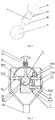
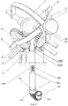
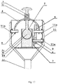
- the device for controlling the movement of the tip of medical insertion tube constituting the medical insertion tube control mechanical system is equipped with a lever 1 which is a cylindrical control rod terminated on one end with a knob 1d providing support for the operator's finger and on the other hand embedded in the base 2a on the a ball joint 2 which has three degrees of freedom, which is formed by a hemispherical bed 2c and a spherical head 2b mounted therein.
- the hemispherical bed 2c is formed in the base 2a of the mechanical system as shown in fig. 3 .
- Sockets with circular holes are formed in the base 2a of the mechanical system: four upper sockets 2a1 arranged at an angle of 90° and two lower sockets 2a2 arranged at 90°, in which inner ends of four upper pins 8 and two lower pins 9 are inserted.
- the sockets have an internal form adapted to the ends of the pins to guarantee free rotation of the pins embedded in these sockets.
- the upper pins 8 and the lower pins 9 can rotate freely in the sockets around their own axes of rotation.
- the upper pins 8 and the lower pins 9 are also embedded with their outer ends in blind holes 11a made in the housing 11 of the entire mechanical system, as shown in Fig. 3 .
- the upper pins 8 and the lower pins 9 with their outer ends can rotate freely in housing holes 11a around their own rotation axis.
- the upper arch guide 3 is guided through the upper passage 1a, and its ends are fixed by a static connection on two coaxially placed upper pins 8.
- the lower arch guide 4 is led through the lower passage 1b and its ends are fixed by a static connection on another two upper pins 8 coaxially placed as well.
- driving gears 5 which form gear transmissions with corresponding driven gears 6 also supported by static connection on the lower pins 9 so that the gears move with the movement of the pins.
- Driving gear 5 with a larger diameter than the diameter of the driven gear 6 coupled to it forms a multiplying transmissions.
- Driving gear 5 with smaller diameter than that connected to it driven gear 6 can be applied and then forms a reducing transmission.
- the pulley 7 is fixed to each driven gear 6, which is mounted on the lower pin 9 in such a way that each driven gear 6 is coupled to the pulley 7 and moves with the rotation of the lower pin 9.
- one tension cable is wound up in a halfway on each pulley 7 in such a manner that each tension cable on the pulley have two free ends, which are then guided through the insertion tube 12 to the movable end 12a e.g. the flexible end and attached they are to its distal tip.
- On one of the pulleys 7 one up-down tension cable 10ab is wound up with two ends whose, when they are pulled or released, cause movement of the movable end of insertion tube in one plane, i.e.
- the up end 10a and the down end 10b allow the tip of the medical insertion tube to move in a set direction in the vertical plane up-down.
- one right-left tension cable 10cd is wound up with two ends: the right end 10c and the left 10d end, which allow the tip of the medical insertion tube to move in a set direction in the horizontal plane, i.e. left-right.
- Mechanical system is enclosed in a housing 11 to forming a handle provided with a insertion tube.
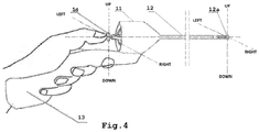
- the mechanical system is designed for controlling medical devices such as, for example, endoscopes equipped with a insertion tube 12 with a movable end 12a, which can be also a flexible end as shown in Fig. 4 .
- the housing 11 of the handle 13 is connected to the proximal end of the insertion tube 12.
- the cables are led inside insertion tube 12 to the movable end 12a and fixed at its distal tip.
- the operator moves the lever 1 constituting the control rod in the given direction.
- the lever 1 thanks to that is settled on the ball joint 2, can tilt in all directions.
- the movement of the lever 1 in a predetermined direction causes the upper arch guide 3 or the lower arch guide 4 or both arch guides to be deflected at the same time, transferring the movement of the lever 1 into the move of the upper pins 8 and the lower pins 9.
- moving the lever 1 in the predetermined direction finally causes the movement of the tip of the insertion tube.
- the control mechanical system causes the movable end 12a to be bent in all directions analogously to the movement of the lever.
- the movable end of the insertion rube can be deflected in a designated direction in the range of -180 ° to 180 ° in each plane.
- the described independency of movements of the arch guides is carried out by sliding the lower passage 1b along the lower arch guide 4 - lower passage 1b is aligned along the axis of rotation of the lower arch guide 4 and perpendicular to the axis of rotation of the upper arch guide 3. Movement of the upper arch guide 3 causes the rotation of two coaxially placed upper pins.
- the driving gear 5 transmits rotation to the driven gear 6, which causes the rotation of one lower pin 9 and at the same time the pulley 7 connected to the driven gear 6.
- the pulley 7 rotating causes movement of the tension cable up-down 10ab making one end shorter the down-end 10b and extending other end, the up-end 10a which causes deflection of the movable end 12a of the insertion tube 12 in the vertical plane in the down direction.
- the lower arch guide 4 and the left-right 10cd tension cable are not moving.
- the deflection of the lever 1 in the horizontal plane in the right direction finally results in the corresponding deflection of the movable end 12a of the insertion tube 12 in the horizontal plane in the right direction.
- the lever 1 during movement causes the lower arch guide 4 to move in the right direction - the lower passage 1b is set along the axis of rotation of the lower arch guide 4 and perpendicular to the axis of rotation of the upper arch guide 3. Movement of the lever 1 in the right direction does not cause movement of the upper arch guide 3, which is allowed by sliding the upper passage 1a along the upper arch guide 3 - the upper passage 1a is positioned along the axis of rotation of the upper arch guide 3 and perpendicular to the axis of rotation of the lower arch guide 4.
- Movement of the lower arch guide 4 causes the rotation of the two coaxially placed pins 8 on which arch guide 4 is seated actuate the driving gear 5 which is mounted on one of those pins.
- the driving gear 5 transmits the rotation to the driven gear 6, which causes also the rotation of one lower pin 9 and the pulley 7 at the same time.
- the pulley 7 through rotation moves wound up tension cable left-right 10cd making shorter the right-end 10c, while extending the left-end 10d which bends the movable end 12a of the insertion tube 12 in the horizontal plane in the right direction.
- the upper arch guide 3 and the up-down 10ab are not moving.
- the lever 1 moving in direction right-up drives the lower arch guide 4 in the right direction and simultaneously moves the upper arch guide 3 towards direction up.
- Simultaneous movement of the upper arch guide 3 and lower arch guide 4 causes a change of the angle between their sections cooperating with the lever 1.
- the change of this angle is possible by the upper passages 1a and the lower passage 1b of the lever 1, which slide on arch guides and rotate on the rotating joint placed between them 1c.
- the angle of their mutual rotation corresponds to the change in the angle between the upper and lower arch guides 4.
- the simultaneous movement of both upper arch guides 3 and lower arch guides 4 causes rotation of the four upper pins 8 together with two driving gears 5 mounted on two of them and placed every 90 degrees.
- the two driving gears 5 transmit the rotary motion to the two driven gears 6, which causes the rotation of the two lower pins 9 and simultaneously the rotation of the two pulleys 7.
- the pulleys 7 through rotation drive wound up on them tension cables.
- the pulley 7 with the wound up up-down tension cable 10ab by rotation pull the end of the up-end 10a and release the down-end 10b.
- the second pulley 7 with the right-left wound up tension cable 10cd rotating pull the right-end 10c and release the left-end 10d.
- Simultaneous pulling of the end of the up-end 10a and the right-end 10c causes the movable end 12a of the insertion tube 12 to deflect between the up and the right direction in the intermediate plane between the vertical and horizontal planes.
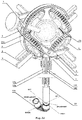
- the mechanical system for controlling the movement of the tip of the medical insertion tube in another embodiment is equipped with a lever 1 which is a cylindrical control rod terminated on one end with a knob 1d supporting the operator's finger and on the other hand embedded in the base 2a on the ball joint 2 with three degrees of freedom, which is formed by a hemispherical bed 2c and a spherical head head 2b embedded therein.
- the hemispherical bed 2c is formed in the base 2a of the mechanical system, as shown in Fig. 3 .
- a upper arch guide 3 and a lower arch guide 4 are guided through the upper part of the lever 1, each of which is mounted on oppositely located to each other upper pins 8.
- through-slots 3a and 4a are formed through which the lever 1 is guided. These slots allow to move the lever 1 in all directions and consequently pushing only one or the other or both arch guides at the same time.
- Both arch guides have a U-shaped form, while on the section cooperating with the lever 1 they have a shape of a part of a ring.
- each socket 2a1 and four lower sockets 2a2 are formed every each with circular blind hole and to these sockets by kinematic connection mounted with their inner ends four upper pins 8 and four lower pins respectively 9.
- the shape of the sockets is adapted to the shape of the ends of pins allowing their rotation in sockets.
- the upper pins and the corresponding sockets are placed at every 90°.
- the lower pins 9 and the corresponding sockets are placed at angle 90°.
- the upper pins 8 and the lower pins 9 by their outer ends are mounted by a kinematic connection in the circular blind holes 11a made in the housing 11 of the mechanical system.
- the deposition of the pins in the housing is analogous to the first example, as shown in Fig. 3 .
- the ends of the upper arch guide 3 are fixed by a static connection on two oppositely located to each other upper pins 8.
- the lower arch guide ends 4 are fixed by a static connection on two another oppositely located to each other upper pins 8.
- driving gear 5 is mounted by a static connection.
- Each the driving gear 5 forms gear transmissions with respective driven gear 6 mounted by a static connection on the lower pins 9, so that the gears move with the movement of the pins.
- a driving gear 5 of larger diameter coupled to the driven gear 6 which has smaller diameter form a multiplying gear transmissions.
- driving gear 5 of smaller diameter coupled to the driven gear 6 which has larger diameter form a reduction gear transmissions.
- Each driven gear 6 is coupled to the pulley 7 and fixed by a static connection on the common lower pin 9 and rotates with this pin.
- each of the four tension cables corresponding to the direction of movement of the movable end 12a is fixed: upper tension cable 10e, lower tension cable 10f, right tension cable 10g, left tension cable 10h.
- the tension cables are only partially wound up onto the pulleys in such a way that one end of each tension cable is permanently fixed on the pulley and the other end passes through the insertion tube 12 to the movable end 12a of the insertion tube 12 and is attached to its distal end.
- the upper tension cable 10e and the lower tension cable 10f deflect the movable end in a predetermined direction in the vertical plane and are partially and counterdriven wound up on the pulleys 7 mounted on coaxially placed lower pins 9.
- the right tension cable 10g and the left tension cable 10h deflect the movable end in the horizontal plane and are partially and counterdriven wound up on the next two pulleys 7 mounted on two further coaxially placed lower pins 9.
- Control of insertion tube tip is performed analogously to the one described in the first example by moving the lever 1 in any directions in the sockets 3a and 3b of the respective arch guides, causing a movement of the upper arch guide 3 or the lower arch guide 4, or both simultaneously, analogously as described in example 1.
- the first pulley 7 by rotation pull and this way makes shorter lower tension cable 10f, the other rotating at the same time releases of the upper tension cable 10e, which causes deflection of the movable end 12a of the insertion tube 12 in the vertical plane in the direction down.
- the upper arch guide 3 and the right tension cable 10g and the left tension cable 10h stay still.
- the tilting the lever 1 in the horizontal plane containing the axis of rotation of the lower arch guide 4 in the right direction and perpendicular to the axis of rotation of the upper arch guide 3 moves the upper arch guide 3 in the right direction and in effect turns two driving gears 5 mounted on the same upper pins 8, on which the upper arch guide 3 is mounted.
- the driving gears 5 moved together with the upper arch guide 3 actuate coupled to these the driven gears 6.
- the movement of the driven gears 6 involves the movement of opposing pulleys 7 mounted on oppositely located to each other lower pins 9.
- the movement of the opposing pulleys 7 sets in motion a partially and counterdriven wound up right tension cable 10g and the left tension cable 10h.
- the first rotating pulley 7 by its rotation make shorter the wound up on that pulled right tension cable 10g, while the second pulley 7 rotates at the same time but releases wound up left tension cable 10h, which causes the deflection of movable end 12a of the insertion tube 12 in the horizontal plane in the direction right.
- Lower arch guide 4 and upper tension cable 10e and lower tension cable 10f stay still.
- the effect of simultaneous pulling of the lower tension cable 10f and the left tension cable 10h is deflection of the tip of the movable end 12a of the insertion tube 12 between left and down direction in the intermediate plane between the vertical and horizontal planes.
- the mechanical system is constructed as described in example 1 or 2 and is shown in fig. 13 but here the lever 1 constituting the control rod is mounted in the base 2a on the universal joint 14 with two degrees of freedom.
- the mechanical system is constructed as described in example 1 or 2 and is shown in fig. 14 , except that the lever 1 constituting the control rod is mounted in the base 2a on the elastic element in the form of a bellows made of a selected elastomer acting like a ball joint and capable of tilting the lever 1 in all directions.
- the flexible element 15 is mounted on the base 2a of the mechanical system.
- the mechanical system is constructed as described in Examples 1-4 or 2 and is shown in Fig. 15 with the difference that in the base 2a of the mechanical system four upper sockets 2a1 and the four lower sockets 2a2 are made with polygonal in cross-sections blind holes to which with their inner ends, respectively, four upper pins 8 and four lower pins 9.
- the shape of the holes in sockets is adapted to the shape of the ends of the pins forming a shape-connection that prevents them from rotating in the sockets.
- the upper pins 8 and the lower pins 9 are also mounted with their outer end by a shape-connection in holes with a polygonal cross-section 11a adapted to the shape of the pins ends and made in the housing 11 of the mechanical system.
- the ends of the upper arch guide 3 are mounted by a kinematic connection on two oppositely located to each other upper pins 8 and are connected by a static connection with driving gears 5.
- the lower arch guide ends 4 are also mounted by a kinematic connection on two another oppositely located to each other upper pins 8 and are also statically connected with driving gears 5.
- Each driving gear 5 forms gear transmissions with respective driven gear 6 mounted by a kinematic connection on the lower pins 9.
- Each driven gear 6 is inseparable from the pulley 7 and is mounted by a kinematic connection on a common lower pin 9.
- the mechanical system is constructed as described in the above examples, and the mounting of the system in the handle of the medical device provided with the insertion tube is carried out in such a way that the upper pins 8 and lower pins 9 are mounted only in the base 2a of the mechanical system, and the mounting of the mechanical system in the housing 11 is realized by combining the base 2a of the mechanical system with the housing wall 11, as shown in Fig. 16
- the mechanical system is constructed as described in the above examples, and the mounting of the system in the handle of the medical device provided with the insertion tube is realized in this way, the upper pins 8 and lower pins 9 are mounted only in the housing 11, and the base 2a of the control system is mounted on the wall of the housing 11, as shown in Fig. 17 .
Landscapes
- Health & Medical Sciences (AREA)
- Life Sciences & Earth Sciences (AREA)
- Engineering & Computer Science (AREA)
- Surgery (AREA)
- General Health & Medical Sciences (AREA)
- Biophysics (AREA)
- Public Health (AREA)
- Biomedical Technology (AREA)
- Heart & Thoracic Surgery (AREA)
- Veterinary Medicine (AREA)
- Animal Behavior & Ethology (AREA)
- Physics & Mathematics (AREA)
- Optics & Photonics (AREA)
- Nuclear Medicine, Radiotherapy & Molecular Imaging (AREA)
- Pathology (AREA)
- Radiology & Medical Imaging (AREA)
- Medical Informatics (AREA)
- Molecular Biology (AREA)
- Hematology (AREA)
- Anesthesiology (AREA)
- Pulmonology (AREA)
- Mechanical Engineering (AREA)
- Astronomy & Astrophysics (AREA)
- General Physics & Mathematics (AREA)
- Instruments For Viewing The Inside Of Hollow Bodies (AREA)
- Endoscopes (AREA)
Applications Claiming Priority (1)
| Application Number | Priority Date | Filing Date | Title |
|---|---|---|---|
| PL422397A PL422397A1 (pl) | 2017-07-29 | 2017-07-29 | Układ do sterowania końcówką sondy medycznej, zwłaszcza sondy endoskopu oraz uchwyt endoskopu |
Publications (2)
| Publication Number | Publication Date |
|---|---|
| EP3434169A1 true EP3434169A1 (de) | 2019-01-30 |
| EP3434169B1 EP3434169B1 (de) | 2022-10-19 |
Family
ID=63578909
Family Applications (1)
| Application Number | Title | Priority Date | Filing Date |
|---|---|---|---|
| EP18185923.2A Active EP3434169B1 (de) | 2017-07-29 | 2018-07-26 | Mechanisches system für distale spitze zur steuerung eines medizinischen einführrohrs, insbesondere ein endoskopeinführrohr, und ein endoskopgriff |
Country Status (3)
| Country | Link |
|---|---|
| US (1) | US20190029498A1 (de) |
| EP (1) | EP3434169B1 (de) |
| PL (2) | PL422397A1 (de) |
Cited By (1)
| Publication number | Priority date | Publication date | Assignee | Title |
|---|---|---|---|---|
| US12390093B2 (en) | 2019-10-28 | 2025-08-19 | Olympus Corporation | Endoscope, bending operation mechanism for endoscope, and operation portion for endoscope |
Families Citing this family (110)
| Publication number | Priority date | Publication date | Assignee | Title |
|---|---|---|---|---|
| WO2006097931A2 (en) | 2005-03-17 | 2006-09-21 | Valtech Cardio, Ltd. | Mitral valve treatment techniques |
| US9883943B2 (en) | 2006-12-05 | 2018-02-06 | Valtech Cardio, Ltd. | Implantation of repair devices in the heart |
| US11259924B2 (en) | 2006-12-05 | 2022-03-01 | Valtech Cardio Ltd. | Implantation of repair devices in the heart |
| US11660190B2 (en) | 2007-03-13 | 2023-05-30 | Edwards Lifesciences Corporation | Tissue anchors, systems and methods, and devices |
| US8382829B1 (en) | 2008-03-10 | 2013-02-26 | Mitralign, Inc. | Method to reduce mitral regurgitation by cinching the commissure of the mitral valve |
| US8652202B2 (en) | 2008-08-22 | 2014-02-18 | Edwards Lifesciences Corporation | Prosthetic heart valve and delivery apparatus |
| US8911494B2 (en) | 2009-05-04 | 2014-12-16 | Valtech Cardio, Ltd. | Deployment techniques for annuloplasty ring |
| US10517719B2 (en) | 2008-12-22 | 2019-12-31 | Valtech Cardio, Ltd. | Implantation of repair devices in the heart |
| US8715342B2 (en) | 2009-05-07 | 2014-05-06 | Valtech Cardio, Ltd. | Annuloplasty ring with intra-ring anchoring |
| US8241351B2 (en) | 2008-12-22 | 2012-08-14 | Valtech Cardio, Ltd. | Adjustable partial annuloplasty ring and mechanism therefor |
| WO2010073246A2 (en) | 2008-12-22 | 2010-07-01 | Valtech Cardio, Ltd. | Adjustable annuloplasty devices and adjustment mechanisms therefor |
| US8353956B2 (en) | 2009-02-17 | 2013-01-15 | Valtech Cardio, Ltd. | Actively-engageable movement-restriction mechanism for use with an annuloplasty structure |
| US9968452B2 (en) | 2009-05-04 | 2018-05-15 | Valtech Cardio, Ltd. | Annuloplasty ring delivery cathethers |
| US12485010B2 (en) | 2009-05-07 | 2025-12-02 | Edwards Lifesciences Innovation (Israel) Ltd. | Multiple anchor delivery tool |
| US10098737B2 (en) | 2009-10-29 | 2018-10-16 | Valtech Cardio, Ltd. | Tissue anchor for annuloplasty device |
| US9180007B2 (en) | 2009-10-29 | 2015-11-10 | Valtech Cardio, Ltd. | Apparatus and method for guide-wire based advancement of an adjustable implant |
| EP2506777B1 (de) | 2009-12-02 | 2020-11-25 | Valtech Cardio, Ltd. | Kombination von einer Spulenanordnung mit helikalem Anker und einem Verabreichungswerkzeug zur Implantation derselben |
| US8449599B2 (en) | 2009-12-04 | 2013-05-28 | Edwards Lifesciences Corporation | Prosthetic valve for replacing mitral valve |
| US10792152B2 (en) | 2011-06-23 | 2020-10-06 | Valtech Cardio, Ltd. | Closed band for percutaneous annuloplasty |
| EP3725269A1 (de) | 2011-06-23 | 2020-10-21 | Valtech Cardio, Ltd. | Verschlusselement zur verwendung mit einer annuloplastiestruktur |
| US8858623B2 (en) | 2011-11-04 | 2014-10-14 | Valtech Cardio, Ltd. | Implant having multiple rotational assemblies |
| EP3970627B1 (de) | 2011-11-08 | 2023-12-20 | Edwards Lifesciences Innovation (Israel) Ltd. | Gesteuerte lenkfunktionalität für ein implantatabgabewerkzeug |
| WO2013088327A1 (en) | 2011-12-12 | 2013-06-20 | David Alon | Heart valve repair device |
| CA2885354A1 (en) | 2012-09-29 | 2014-04-03 | Mitralign, Inc. | Plication lock delivery system and method of use thereof |
| US9949828B2 (en) | 2012-10-23 | 2018-04-24 | Valtech Cardio, Ltd. | Controlled steering functionality for implant-delivery tool |
| EP2911593B1 (de) | 2012-10-23 | 2020-03-25 | Valtech Cardio, Ltd. | Perkutane gewebeankertechniken |
| WO2014087402A1 (en) | 2012-12-06 | 2014-06-12 | Valtech Cardio, Ltd. | Techniques for guide-wire based advancement of a tool |
| US9439763B2 (en) | 2013-02-04 | 2016-09-13 | Edwards Lifesciences Corporation | Prosthetic valve for replacing mitral valve |
| WO2014134183A1 (en) | 2013-02-26 | 2014-09-04 | Mitralign, Inc. | Devices and methods for percutaneous tricuspid valve repair |
| US10449333B2 (en) | 2013-03-14 | 2019-10-22 | Valtech Cardio, Ltd. | Guidewire feeder |
| US9724195B2 (en) | 2013-03-15 | 2017-08-08 | Mitralign, Inc. | Translation catheters and systems |
| US10070857B2 (en) | 2013-08-31 | 2018-09-11 | Mitralign, Inc. | Devices and methods for locating and implanting tissue anchors at mitral valve commissure |
| US10299793B2 (en) | 2013-10-23 | 2019-05-28 | Valtech Cardio, Ltd. | Anchor magazine |
| US9622863B2 (en) | 2013-11-22 | 2017-04-18 | Edwards Lifesciences Corporation | Aortic insufficiency repair device and method |
| US9610162B2 (en) | 2013-12-26 | 2017-04-04 | Valtech Cardio, Ltd. | Implantation of flexible implant |
| EP4331503A3 (de) | 2014-10-14 | 2024-06-05 | Edwards Lifesciences Innovation (Israel) Ltd. | Segelrückhaltetechniken |
| CN107205817B (zh) | 2014-12-04 | 2020-04-03 | 爱德华兹生命科学公司 | 用于修复心脏瓣膜的经皮夹具 |
| US20160256269A1 (en) | 2015-03-05 | 2016-09-08 | Mitralign, Inc. | Devices for treating paravalvular leakage and methods use thereof |
| SG11201708397PA (en) | 2015-04-30 | 2017-11-29 | Valtech Cardio Ltd | Annuloplasty technologies |
| EP4420635B1 (de) | 2015-05-14 | 2025-09-24 | Edwards Lifesciences Corporation | Herzklappenverschlussvorrichtungen und freisetzungsvorrichtungen dafür |
| EP3397207B1 (de) | 2015-12-30 | 2026-04-01 | Edwards Lifesciences Corporation | System zur reduzierung von triskupidalklappenregurgitation |
| US10835714B2 (en) | 2016-03-21 | 2020-11-17 | Edwards Lifesciences Corporation | Multi-direction steerable handles for steering catheters |
| US10799675B2 (en) | 2016-03-21 | 2020-10-13 | Edwards Lifesciences Corporation | Cam controlled multi-direction steerable handles |
| US11219746B2 (en) | 2016-03-21 | 2022-01-11 | Edwards Lifesciences Corporation | Multi-direction steerable handles for steering catheters |
| US10799676B2 (en) * | 2016-03-21 | 2020-10-13 | Edwards Lifesciences Corporation | Multi-direction steerable handles for steering catheters |
| US10799677B2 (en) | 2016-03-21 | 2020-10-13 | Edwards Lifesciences Corporation | Multi-direction steerable handles for steering catheters |
| US10702274B2 (en) | 2016-05-26 | 2020-07-07 | Edwards Lifesciences Corporation | Method and system for closing left atrial appendage |
| US10973638B2 (en) | 2016-07-07 | 2021-04-13 | Edwards Lifesciences Corporation | Device and method for treating vascular insufficiency |
| GB201611910D0 (en) | 2016-07-08 | 2016-08-24 | Valtech Cardio Ltd | Adjustable annuloplasty device with alternating peaks and troughs |
| US10653862B2 (en) | 2016-11-07 | 2020-05-19 | Edwards Lifesciences Corporation | Apparatus for the introduction and manipulation of multiple telescoping catheters |
| US10905554B2 (en) | 2017-01-05 | 2021-02-02 | Edwards Lifesciences Corporation | Heart valve coaptation device |
| US11224511B2 (en) | 2017-04-18 | 2022-01-18 | Edwards Lifesciences Corporation | Heart valve sealing devices and delivery devices therefor |
| US11045627B2 (en) | 2017-04-18 | 2021-06-29 | Edwards Lifesciences Corporation | Catheter system with linear actuation control mechanism |
| SG11201907076YA (en) | 2017-04-18 | 2019-08-27 | Edwards Lifesciences Corp | Heart valve sealing devices and delivery devices therefor |
| US10799312B2 (en) | 2017-04-28 | 2020-10-13 | Edwards Lifesciences Corporation | Medical device stabilizing apparatus and method of use |
| US10959846B2 (en) | 2017-05-10 | 2021-03-30 | Edwards Lifesciences Corporation | Mitral valve spacer device |
| US11051940B2 (en) | 2017-09-07 | 2021-07-06 | Edwards Lifesciences Corporation | Prosthetic spacer device for heart valve |
| US11065117B2 (en) | 2017-09-08 | 2021-07-20 | Edwards Lifesciences Corporation | Axisymmetric adjustable device for treating mitral regurgitation |
| US11040174B2 (en) | 2017-09-19 | 2021-06-22 | Edwards Lifesciences Corporation | Multi-direction steerable handles for steering catheters |
| US10835221B2 (en) | 2017-11-02 | 2020-11-17 | Valtech Cardio, Ltd. | Implant-cinching devices and systems |
| US11135062B2 (en) | 2017-11-20 | 2021-10-05 | Valtech Cardio Ltd. | Cinching of dilated heart muscle |
| US10105222B1 (en) | 2018-01-09 | 2018-10-23 | Edwards Lifesciences Corporation | Native valve repair devices and procedures |
| US10076415B1 (en) | 2018-01-09 | 2018-09-18 | Edwards Lifesciences Corporation | Native valve repair devices and procedures |
| US10245144B1 (en) | 2018-01-09 | 2019-04-02 | Edwards Lifesciences Corporation | Native valve repair devices and procedures |
| US10231837B1 (en) | 2018-01-09 | 2019-03-19 | Edwards Lifesciences Corporation | Native valve repair devices and procedures |
| US10159570B1 (en) | 2018-01-09 | 2018-12-25 | Edwards Lifesciences Corporation | Native valve repair devices and procedures |
| US10973639B2 (en) | 2018-01-09 | 2021-04-13 | Edwards Lifesciences Corporation | Native valve repair devices and procedures |
| US10136993B1 (en) | 2018-01-09 | 2018-11-27 | Edwards Lifesciences Corporation | Native valve repair devices and procedures |
| LT3964175T (lt) | 2018-01-09 | 2024-10-25 | Edwards Lifesciences Corporation | Įgimto vožtuvo taisymo įtaisai |
| US10123873B1 (en) | 2018-01-09 | 2018-11-13 | Edwards Lifesciences Corporation | Native valve repair devices and procedures |
| US10111751B1 (en) | 2018-01-09 | 2018-10-30 | Edwards Lifesciences Corporation | Native valve repair devices and procedures |
| US10238493B1 (en) | 2018-01-09 | 2019-03-26 | Edwards Lifesciences Corporation | Native valve repair devices and procedures |
| WO2019145947A1 (en) | 2018-01-24 | 2019-08-01 | Valtech Cardio, Ltd. | Contraction of an annuloplasty structure |
| EP3743014B1 (de) | 2018-01-26 | 2023-07-19 | Edwards Lifesciences Innovation (Israel) Ltd. | Techniken zur erleichterung von herzklappen-tethering und sehnenaustausch |
| US11389297B2 (en) | 2018-04-12 | 2022-07-19 | Edwards Lifesciences Corporation | Mitral valve spacer device |
| US11207181B2 (en) | 2018-04-18 | 2021-12-28 | Edwards Lifesciences Corporation | Heart valve sealing devices and delivery devices therefor |
| CN120000269A (zh) | 2018-07-12 | 2025-05-16 | 爱德华兹生命科学创新(以色列)有限公司 | 瓣环成形系统及其锁定工具 |
| US10945844B2 (en) | 2018-10-10 | 2021-03-16 | Edwards Lifesciences Corporation | Heart valve sealing devices and delivery devices therefor |
| CA3118722A1 (en) | 2018-11-20 | 2020-05-28 | Edwards Lifesciences Corporation | Deployment tools and methods for delivering a device to a native heart valve |
| SG11202105286SA (en) | 2018-11-21 | 2021-06-29 | Edwards Lifesciences Corp | Heart valve sealing devices, delivery devices therefor, and retrieval devices |
| SG11202105391SA (en) | 2018-11-29 | 2021-06-29 | Edwards Lifesciences Corp | Catheterization method and apparatus |
| JP2022520377A (ja) | 2019-02-11 | 2022-03-30 | エドワーズ ライフサイエンシーズ コーポレイション | 心臓弁封止デバイスおよびその送達デバイス |
| PL3923867T3 (pl) | 2019-02-14 | 2024-05-27 | Edwards Lifesciences Corporation | Urządzenia do uszczelniania zastawek serca i urządzenia do ich wprowadzania |
| SG11202108606PA (en) | 2019-02-25 | 2021-09-29 | Edwards Lifesciences Corp | Heart valve sealing devices |
| CN109896358B (zh) * | 2019-04-19 | 2024-02-23 | 上海熠达光电科技有限公司 | 插入管卷绕装置 |
| AU2020284630A1 (en) | 2019-05-29 | 2021-11-18 | Edwards Lifesciences Innovation (Israel) Ltd. | Tissue anchor handling systems and methods |
| US12502167B2 (en) | 2019-07-16 | 2025-12-23 | Edwards Lifesciences Corporation | Tissue remodeling systems and methods |
| US12364606B2 (en) | 2019-07-23 | 2025-07-22 | Edwards Lifesciences Innovation (Israel) Ltd. | Fluoroscopic visualization of heart valve anatomy |
| CA3141295A1 (en) | 2019-07-23 | 2021-01-28 | Valtech Cardio, Ltd. | Contraction of an annuloplasty structure |
| WO2021038560A1 (en) | 2019-08-28 | 2021-03-04 | Valtech Cardio, Ltd. | Low-profile steerable catheter |
| EP4021350B1 (de) | 2019-08-30 | 2024-12-18 | Edwards Lifesciences Innovation (Israel) Ltd. | Ankerkanalspitze |
| KR20220066398A (ko) | 2019-09-25 | 2022-05-24 | 카디악 임플란츠 엘엘씨 | 심장 판막 고리 감소 시스템 |
| CN114502056B (zh) * | 2019-10-11 | 2025-12-30 | 奥林巴斯株式会社 | 内窥镜的弯曲操作机构和内窥镜 |
| CR20210635A (es) | 2019-10-15 | 2022-05-30 | Edwards Lifesciences Corp | Dispositivos de sellado de válvulas cardíacas y dispositivos de administración de los mismos |
| KR20220122966A (ko) | 2019-10-29 | 2022-09-05 | 에드워즈 라이프사이언시스 이노베이션 (이스라엘) 리미티드 | 고리 성형술 및 조직 앵커 기술 |
| EP4096529B1 (de) | 2020-03-23 | 2025-05-07 | Edwards Lifesciences Innovation (Israel) Ltd. | Selbstsichernde winde |
| DE102020111885A1 (de) | 2020-04-30 | 2021-11-04 | Ambu A/S | Lenkanordnung für ein Endoskop, insbesondere für ein Einwegendoskop |
| US12011146B2 (en) | 2020-04-30 | 2024-06-18 | Ambu A/S | Method of assembly of an endoscope control system |
| JP2023527304A (ja) | 2020-05-20 | 2023-06-28 | カーディアック・インプランツ・エルエルシー | 心臓弁輪に打ち込まれるアンカそれぞれを独立的に制御することによる心臓弁輪の直径の減少 |
| US12207795B2 (en) * | 2020-06-11 | 2025-01-28 | Boston Scientific Medical Device Limited | Medical systems, devices and related methods |
| EP4606322A1 (de) | 2020-06-19 | 2025-08-27 | Edwards Lifesciences Innovation (Israel) Ltd. | Selbststoppende gewebeanker |
| US11654262B2 (en) * | 2020-08-26 | 2023-05-23 | Freudenberg Medical, Llc | Handle assembly for controlling a steerable catheter |
| CN116171140A (zh) | 2020-09-01 | 2023-05-26 | 爱德华兹生命科学公司 | 医疗装置稳定系统 |
| JP7806034B2 (ja) * | 2020-09-22 | 2026-01-26 | ボストン サイエンティフィック メディカル デバイス リミテッド | 関節式医療装置及びそれを使用する方法 |
| CA3211709A1 (en) | 2021-03-03 | 2022-09-09 | Boston Scientific Scimed, Inc. | Medical device including a medical device management system |
| CN114838102A (zh) * | 2022-04-08 | 2022-08-02 | 精勤智造(苏州)医疗科技有限公司 | 一种柔性万向关节齿轮摇杆驱动结构 |
| WO2023225209A1 (en) | 2022-05-20 | 2023-11-23 | Boston Scientific Scimed, Inc. | Trajectory tracking for medical device |
| US20240349999A1 (en) * | 2023-04-18 | 2024-10-24 | Gregory Brian BOWLES | Remotely operated hand-held bronchoscope |
| USD1071198S1 (en) | 2023-06-28 | 2025-04-15 | Edwards Lifesciences Corporation | Cradle |
| WO2026042260A1 (ja) * | 2024-08-23 | 2026-02-26 | オリンパスメディカルシステムズ株式会社 | 内視鏡 |
Citations (5)
| Publication number | Priority date | Publication date | Assignee | Title |
|---|---|---|---|---|
| US20040059191A1 (en) * | 2002-06-17 | 2004-03-25 | Robert Krupa | Mechanical steering mechanism for borescopes, endoscopes, catheters, guide tubes, and working tools |
| EP1886617A1 (de) * | 2005-05-26 | 2008-02-13 | Ars Co., Ltd. | Endoskopvorrichtung |
| EP2745765A1 (de) * | 2012-06-21 | 2014-06-25 | Olympus Medical Systems Corp. | Einsetzvorrichtung |
| US20140251042A1 (en) * | 2013-03-11 | 2014-09-11 | Boston Scientific Scimed, Inc. | Deflection mechanism |
| WO2015088142A1 (ko) * | 2013-12-09 | 2015-06-18 | 주식회사 현주인테크 | 카테터 또는 내시경용 제어장치 |
Family Cites Families (4)
| Publication number | Priority date | Publication date | Assignee | Title |
|---|---|---|---|---|
| US5413107A (en) * | 1994-02-16 | 1995-05-09 | Tetrad Corporation | Ultrasonic probe having articulated structure and rotatable transducer head |
| US7789826B2 (en) * | 2004-09-30 | 2010-09-07 | Boston Scientific Scimed, Inc. | Manually controlled endoscope |
| AU2007254126A1 (en) * | 2006-05-19 | 2007-11-29 | Conmed Endoscopic Technologies, Inc. | Steerable medical instrument |
| US8048024B2 (en) * | 2008-03-17 | 2011-11-01 | Boston Scientific Scimed, Inc. | Steering mechanism |
-
2017
- 2017-07-29 PL PL422397A patent/PL422397A1/pl unknown
-
2018
- 2018-07-26 PL PL18185923.2T patent/PL3434169T3/pl unknown
- 2018-07-26 EP EP18185923.2A patent/EP3434169B1/de active Active
- 2018-07-27 US US16/048,086 patent/US20190029498A1/en not_active Abandoned
Patent Citations (5)
| Publication number | Priority date | Publication date | Assignee | Title |
|---|---|---|---|---|
| US20040059191A1 (en) * | 2002-06-17 | 2004-03-25 | Robert Krupa | Mechanical steering mechanism for borescopes, endoscopes, catheters, guide tubes, and working tools |
| EP1886617A1 (de) * | 2005-05-26 | 2008-02-13 | Ars Co., Ltd. | Endoskopvorrichtung |
| EP2745765A1 (de) * | 2012-06-21 | 2014-06-25 | Olympus Medical Systems Corp. | Einsetzvorrichtung |
| US20140251042A1 (en) * | 2013-03-11 | 2014-09-11 | Boston Scientific Scimed, Inc. | Deflection mechanism |
| WO2015088142A1 (ko) * | 2013-12-09 | 2015-06-18 | 주식회사 현주인테크 | 카테터 또는 내시경용 제어장치 |
Cited By (1)
| Publication number | Priority date | Publication date | Assignee | Title |
|---|---|---|---|---|
| US12390093B2 (en) | 2019-10-28 | 2025-08-19 | Olympus Corporation | Endoscope, bending operation mechanism for endoscope, and operation portion for endoscope |
Also Published As
| Publication number | Publication date |
|---|---|
| PL3434169T3 (pl) | 2023-06-12 |
| EP3434169B1 (de) | 2022-10-19 |
| PL422397A1 (pl) | 2019-02-11 |
| US20190029498A1 (en) | 2019-01-31 |
Similar Documents
| Publication | Publication Date | Title |
|---|---|---|
| EP3434169B1 (de) | Mechanisches system für distale spitze zur steuerung eines medizinischen einführrohrs, insbesondere ein endoskopeinführrohr, und ein endoskopgriff | |
| US11903559B2 (en) | Surgeon controlled endoscope device and method | |
| US8133171B2 (en) | Wire spring guide for flexible endoscope | |
| JP6274630B2 (ja) | 多関節器具位置決め装置およびそれを採用するシステム | |
| US9936860B2 (en) | Bending apparatus | |
| EP1740084A2 (de) | Endoskopische chirurgische zugangsvorrichtungen und verfahren zur gliederung eines externen zugangskanals | |
| AU2006213225A1 (en) | Flexible tube for endoscope, and endoscope device | |
| EP4183309B1 (de) | Endoskop mit verzahntem anhebemechanismus | |
| CN110269686B (zh) | 具有转动部的连接组件、操作臂及手术机器人 | |
| JP6180679B2 (ja) | 内視鏡 | |
| JP2008220972A (ja) | 処置具 | |
| US12178405B2 (en) | Endoscope having tension adjustment part | |
| CN117320608A (zh) | 包括铰链长度变化的弯曲区段的内窥镜 | |
| US20170007346A1 (en) | Treatment device and surgical system | |
| JP2008220971A (ja) | 処置具 | |
| JP6203132B2 (ja) | ガイド装置および手術システム | |
| EP2123231B1 (de) | Biegerohr und medizinische Vorrichtung | |
| JP4145309B2 (ja) | 処置具 | |
| JP6689589B2 (ja) | 内視鏡 | |
| CN119110702A (zh) | 用于将构件伸缩穿过长形管的系统 | |
| KR20250006157A (ko) | 의료 디바이스용 액추에이터 및 관련 시스템 및 방법 | |
| JP2018175225A (ja) | 内視鏡システム | |
| WO2023191056A1 (ja) | 医療用デバイス | |
| JP2025513293A (ja) | 医療装置並びに関連するシステム及び方法 |
Legal Events
| Date | Code | Title | Description |
|---|---|---|---|
| PUAI | Public reference made under article 153(3) epc to a published international application that has entered the european phase |
Free format text: ORIGINAL CODE: 0009012 |
|
| STAA | Information on the status of an ep patent application or granted ep patent |
Free format text: STATUS: THE APPLICATION HAS BEEN PUBLISHED |
|
| AK | Designated contracting states |
Kind code of ref document: A1 Designated state(s): AL AT BE BG CH CY CZ DE DK EE ES FI FR GB GR HR HU IE IS IT LI LT LU LV MC MK MT NL NO PL PT RO RS SE SI SK SM TR |
|
| AX | Request for extension of the european patent |
Extension state: BA ME |
|
| STAA | Information on the status of an ep patent application or granted ep patent |
Free format text: STATUS: REQUEST FOR EXAMINATION WAS MADE |
|
| 17P | Request for examination filed |
Effective date: 20190131 |
|
| RBV | Designated contracting states (corrected) |
Designated state(s): AL AT BE BG CH CY CZ DE DK EE ES FI FR GB GR HR HU IE IS IT LI LT LU LV MC MK MT NL NO PL PT RO RS SE SI SK SM TR |
|
| GRAP | Despatch of communication of intention to grant a patent |
Free format text: ORIGINAL CODE: EPIDOSNIGR1 |
|
| STAA | Information on the status of an ep patent application or granted ep patent |
Free format text: STATUS: GRANT OF PATENT IS INTENDED |
|
| INTG | Intention to grant announced |
Effective date: 20220519 |
|
| GRAS | Grant fee paid |
Free format text: ORIGINAL CODE: EPIDOSNIGR3 |
|
| GRAA | (expected) grant |
Free format text: ORIGINAL CODE: 0009210 |
|
| STAA | Information on the status of an ep patent application or granted ep patent |
Free format text: STATUS: THE PATENT HAS BEEN GRANTED |
|
| AK | Designated contracting states |
Kind code of ref document: B1 Designated state(s): AL AT BE BG CH CY CZ DE DK EE ES FI FR GB GR HR HU IE IS IT LI LT LU LV MC MK MT NL NO PL PT RO RS SE SI SK SM TR |
|
| REG | Reference to a national code |
Ref country code: GB Ref legal event code: FG4D |
|
| REG | Reference to a national code |
Ref country code: CH Ref legal event code: EP |
|
| REG | Reference to a national code |
Ref country code: IE Ref legal event code: FG4D |
|
| REG | Reference to a national code |
Ref country code: DE Ref legal event code: R096 Ref document number: 602018041895 Country of ref document: DE |
|
| REG | Reference to a national code |
Ref country code: AT Ref legal event code: REF Ref document number: 1525055 Country of ref document: AT Kind code of ref document: T Effective date: 20221115 |
|
| REG | Reference to a national code |
Ref country code: LT Ref legal event code: MG9D |
|
| REG | Reference to a national code |
Ref country code: NL Ref legal event code: MP Effective date: 20221019 |
|
| REG | Reference to a national code |
Ref country code: AT Ref legal event code: MK05 Ref document number: 1525055 Country of ref document: AT Kind code of ref document: T Effective date: 20221019 |
|
| PG25 | Lapsed in a contracting state [announced via postgrant information from national office to epo] |
Ref country code: NL Free format text: LAPSE BECAUSE OF FAILURE TO SUBMIT A TRANSLATION OF THE DESCRIPTION OR TO PAY THE FEE WITHIN THE PRESCRIBED TIME-LIMIT Effective date: 20221019 |
|
| PG25 | Lapsed in a contracting state [announced via postgrant information from national office to epo] |
Ref country code: SE Free format text: LAPSE BECAUSE OF FAILURE TO SUBMIT A TRANSLATION OF THE DESCRIPTION OR TO PAY THE FEE WITHIN THE PRESCRIBED TIME-LIMIT Effective date: 20221019 Ref country code: PT Free format text: LAPSE BECAUSE OF FAILURE TO SUBMIT A TRANSLATION OF THE DESCRIPTION OR TO PAY THE FEE WITHIN THE PRESCRIBED TIME-LIMIT Effective date: 20230220 Ref country code: NO Free format text: LAPSE BECAUSE OF FAILURE TO SUBMIT A TRANSLATION OF THE DESCRIPTION OR TO PAY THE FEE WITHIN THE PRESCRIBED TIME-LIMIT Effective date: 20230119 Ref country code: LT Free format text: LAPSE BECAUSE OF FAILURE TO SUBMIT A TRANSLATION OF THE DESCRIPTION OR TO PAY THE FEE WITHIN THE PRESCRIBED TIME-LIMIT Effective date: 20221019 Ref country code: FI Free format text: LAPSE BECAUSE OF FAILURE TO SUBMIT A TRANSLATION OF THE DESCRIPTION OR TO PAY THE FEE WITHIN THE PRESCRIBED TIME-LIMIT Effective date: 20221019 Ref country code: ES Free format text: LAPSE BECAUSE OF FAILURE TO SUBMIT A TRANSLATION OF THE DESCRIPTION OR TO PAY THE FEE WITHIN THE PRESCRIBED TIME-LIMIT Effective date: 20221019 Ref country code: AT Free format text: LAPSE BECAUSE OF FAILURE TO SUBMIT A TRANSLATION OF THE DESCRIPTION OR TO PAY THE FEE WITHIN THE PRESCRIBED TIME-LIMIT Effective date: 20221019 |
|
| PG25 | Lapsed in a contracting state [announced via postgrant information from national office to epo] |
Ref country code: RS Free format text: LAPSE BECAUSE OF FAILURE TO SUBMIT A TRANSLATION OF THE DESCRIPTION OR TO PAY THE FEE WITHIN THE PRESCRIBED TIME-LIMIT Effective date: 20221019 Ref country code: LV Free format text: LAPSE BECAUSE OF FAILURE TO SUBMIT A TRANSLATION OF THE DESCRIPTION OR TO PAY THE FEE WITHIN THE PRESCRIBED TIME-LIMIT Effective date: 20221019 Ref country code: IS Free format text: LAPSE BECAUSE OF FAILURE TO SUBMIT A TRANSLATION OF THE DESCRIPTION OR TO PAY THE FEE WITHIN THE PRESCRIBED TIME-LIMIT Effective date: 20230219 Ref country code: HR Free format text: LAPSE BECAUSE OF FAILURE TO SUBMIT A TRANSLATION OF THE DESCRIPTION OR TO PAY THE FEE WITHIN THE PRESCRIBED TIME-LIMIT Effective date: 20221019 Ref country code: GR Free format text: LAPSE BECAUSE OF FAILURE TO SUBMIT A TRANSLATION OF THE DESCRIPTION OR TO PAY THE FEE WITHIN THE PRESCRIBED TIME-LIMIT Effective date: 20230120 |
|
| REG | Reference to a national code |
Ref country code: DE Ref legal event code: R097 Ref document number: 602018041895 Country of ref document: DE |
|
| PG25 | Lapsed in a contracting state [announced via postgrant information from national office to epo] |
Ref country code: SM Free format text: LAPSE BECAUSE OF FAILURE TO SUBMIT A TRANSLATION OF THE DESCRIPTION OR TO PAY THE FEE WITHIN THE PRESCRIBED TIME-LIMIT Effective date: 20221019 Ref country code: RO Free format text: LAPSE BECAUSE OF FAILURE TO SUBMIT A TRANSLATION OF THE DESCRIPTION OR TO PAY THE FEE WITHIN THE PRESCRIBED TIME-LIMIT Effective date: 20221019 Ref country code: EE Free format text: LAPSE BECAUSE OF FAILURE TO SUBMIT A TRANSLATION OF THE DESCRIPTION OR TO PAY THE FEE WITHIN THE PRESCRIBED TIME-LIMIT Effective date: 20221019 Ref country code: DK Free format text: LAPSE BECAUSE OF FAILURE TO SUBMIT A TRANSLATION OF THE DESCRIPTION OR TO PAY THE FEE WITHIN THE PRESCRIBED TIME-LIMIT Effective date: 20221019 Ref country code: CZ Free format text: LAPSE BECAUSE OF FAILURE TO SUBMIT A TRANSLATION OF THE DESCRIPTION OR TO PAY THE FEE WITHIN THE PRESCRIBED TIME-LIMIT Effective date: 20221019 |
|
| PLBE | No opposition filed within time limit |
Free format text: ORIGINAL CODE: 0009261 |
|
| STAA | Information on the status of an ep patent application or granted ep patent |
Free format text: STATUS: NO OPPOSITION FILED WITHIN TIME LIMIT |
|
| PG25 | Lapsed in a contracting state [announced via postgrant information from national office to epo] |
Ref country code: SK Free format text: LAPSE BECAUSE OF FAILURE TO SUBMIT A TRANSLATION OF THE DESCRIPTION OR TO PAY THE FEE WITHIN THE PRESCRIBED TIME-LIMIT Effective date: 20221019 Ref country code: AL Free format text: LAPSE BECAUSE OF FAILURE TO SUBMIT A TRANSLATION OF THE DESCRIPTION OR TO PAY THE FEE WITHIN THE PRESCRIBED TIME-LIMIT Effective date: 20221019 |
|
| 26N | No opposition filed |
Effective date: 20230720 |
|
| PG25 | Lapsed in a contracting state [announced via postgrant information from national office to epo] |
Ref country code: SI Free format text: LAPSE BECAUSE OF FAILURE TO SUBMIT A TRANSLATION OF THE DESCRIPTION OR TO PAY THE FEE WITHIN THE PRESCRIBED TIME-LIMIT Effective date: 20221019 |
|
| PG25 | Lapsed in a contracting state [announced via postgrant information from national office to epo] |
Ref country code: MC Free format text: LAPSE BECAUSE OF FAILURE TO SUBMIT A TRANSLATION OF THE DESCRIPTION OR TO PAY THE FEE WITHIN THE PRESCRIBED TIME-LIMIT Effective date: 20221019 |
|
| PG25 | Lapsed in a contracting state [announced via postgrant information from national office to epo] |
Ref country code: MC Free format text: LAPSE BECAUSE OF FAILURE TO SUBMIT A TRANSLATION OF THE DESCRIPTION OR TO PAY THE FEE WITHIN THE PRESCRIBED TIME-LIMIT Effective date: 20221019 |
|
| REG | Reference to a national code |
Ref country code: CH Ref legal event code: PL |
|
| REG | Reference to a national code |
Ref country code: BE Ref legal event code: MM Effective date: 20230731 |
|
| PG25 | Lapsed in a contracting state [announced via postgrant information from national office to epo] |
Ref country code: LU Free format text: LAPSE BECAUSE OF NON-PAYMENT OF DUE FEES Effective date: 20230726 |
|
| PG25 | Lapsed in a contracting state [announced via postgrant information from national office to epo] |
Ref country code: LU Free format text: LAPSE BECAUSE OF NON-PAYMENT OF DUE FEES Effective date: 20230726 |
|
| REG | Reference to a national code |
Ref country code: IE Ref legal event code: MM4A |
|
| PG25 | Lapsed in a contracting state [announced via postgrant information from national office to epo] |
Ref country code: CH Free format text: LAPSE BECAUSE OF NON-PAYMENT OF DUE FEES Effective date: 20230731 |
|
| PG25 | Lapsed in a contracting state [announced via postgrant information from national office to epo] |
Ref country code: IT Free format text: LAPSE BECAUSE OF FAILURE TO SUBMIT A TRANSLATION OF THE DESCRIPTION OR TO PAY THE FEE WITHIN THE PRESCRIBED TIME-LIMIT Effective date: 20221019 Ref country code: BE Free format text: LAPSE BECAUSE OF NON-PAYMENT OF DUE FEES Effective date: 20230731 |
|
| PG25 | Lapsed in a contracting state [announced via postgrant information from national office to epo] |
Ref country code: IE Free format text: LAPSE BECAUSE OF NON-PAYMENT OF DUE FEES Effective date: 20230726 |
|
| PG25 | Lapsed in a contracting state [announced via postgrant information from national office to epo] |
Ref country code: IE Free format text: LAPSE BECAUSE OF NON-PAYMENT OF DUE FEES Effective date: 20230726 |
|
| PG25 | Lapsed in a contracting state [announced via postgrant information from national office to epo] |
Ref country code: BG Free format text: LAPSE BECAUSE OF FAILURE TO SUBMIT A TRANSLATION OF THE DESCRIPTION OR TO PAY THE FEE WITHIN THE PRESCRIBED TIME-LIMIT Effective date: 20221019 |
|
| PG25 | Lapsed in a contracting state [announced via postgrant information from national office to epo] |
Ref country code: BG Free format text: LAPSE BECAUSE OF FAILURE TO SUBMIT A TRANSLATION OF THE DESCRIPTION OR TO PAY THE FEE WITHIN THE PRESCRIBED TIME-LIMIT Effective date: 20221019 |
|
| PGFP | Annual fee paid to national office [announced via postgrant information from national office to epo] |
Ref country code: PL Payment date: 20250613 Year of fee payment: 8 |
|
| PGFP | Annual fee paid to national office [announced via postgrant information from national office to epo] |
Ref country code: GB Payment date: 20250618 Year of fee payment: 8 |
|
| PG25 | Lapsed in a contracting state [announced via postgrant information from national office to epo] |
Ref country code: CY Free format text: LAPSE BECAUSE OF FAILURE TO SUBMIT A TRANSLATION OF THE DESCRIPTION OR TO PAY THE FEE WITHIN THE PRESCRIBED TIME-LIMIT; INVALID AB INITIO Effective date: 20180726 |
|
| PG25 | Lapsed in a contracting state [announced via postgrant information from national office to epo] |
Ref country code: HU Free format text: LAPSE BECAUSE OF FAILURE TO SUBMIT A TRANSLATION OF THE DESCRIPTION OR TO PAY THE FEE WITHIN THE PRESCRIBED TIME-LIMIT; INVALID AB INITIO Effective date: 20180726 |
|
| PGFP | Annual fee paid to national office [announced via postgrant information from national office to epo] |
Ref country code: DE Payment date: 20250616 Year of fee payment: 8 |
|
| PGFP | Annual fee paid to national office [announced via postgrant information from national office to epo] |
Ref country code: FR Payment date: 20250709 Year of fee payment: 8 |
|
| PG25 | Lapsed in a contracting state [announced via postgrant information from national office to epo] |
Ref country code: TR Free format text: LAPSE BECAUSE OF FAILURE TO SUBMIT A TRANSLATION OF THE DESCRIPTION OR TO PAY THE FEE WITHIN THE PRESCRIBED TIME-LIMIT Effective date: 20221019 |