EP3434207A1 - Instrument chirurgical - Google Patents
Instrument chirurgical Download PDFInfo
- Publication number
- EP3434207A1 EP3434207A1 EP18184347.5A EP18184347A EP3434207A1 EP 3434207 A1 EP3434207 A1 EP 3434207A1 EP 18184347 A EP18184347 A EP 18184347A EP 3434207 A1 EP3434207 A1 EP 3434207A1
- Authority
- EP
- European Patent Office
- Prior art keywords
- tool
- unit
- surgical instrument
- tool element
- coupling element
- Prior art date
- Legal status (The legal status is an assumption and is not a legal conclusion. Google has not performed a legal analysis and makes no representation as to the accuracy of the status listed.)
- Granted
Links
Images




Classifications
-
- A—HUMAN NECESSITIES
- A61—MEDICAL OR VETERINARY SCIENCE; HYGIENE
- A61B—DIAGNOSIS; SURGERY; IDENTIFICATION
- A61B17/00—Surgical instruments, devices or methods
- A61B17/28—Surgical forceps
- A61B17/29—Forceps for use in minimally invasive surgery
-
- A—HUMAN NECESSITIES
- A61—MEDICAL OR VETERINARY SCIENCE; HYGIENE
- A61B—DIAGNOSIS; SURGERY; IDENTIFICATION
- A61B17/00—Surgical instruments, devices or methods
- A61B17/16—Instruments for performing osteoclasis; Drills or chisels for bones; Trepans
- A61B17/1604—Chisels; Rongeurs; Punches; Stamps
- A61B17/1606—Chisels; Rongeurs; Punches; Stamps of forceps type, i.e. having two jaw elements moving relative to each other
- A61B17/1608—Chisels; Rongeurs; Punches; Stamps of forceps type, i.e. having two jaw elements moving relative to each other the two jaw elements being linked to two elongated shaft elements moving longitudinally relative to each other
- A61B17/1611—Chisels; Rongeurs; Punches; Stamps of forceps type, i.e. having two jaw elements moving relative to each other the two jaw elements being linked to two elongated shaft elements moving longitudinally relative to each other the two jaw elements being integral with respective elongate shaft elements
-
- A—HUMAN NECESSITIES
- A61—MEDICAL OR VETERINARY SCIENCE; HYGIENE
- A61B—DIAGNOSIS; SURGERY; IDENTIFICATION
- A61B90/00—Instruments, implements or accessories specially adapted for surgery or diagnosis and not covered by any of the groups A61B1/00 - A61B50/00, e.g. for luxation treatment or for protecting wound edges
- A61B90/08—Accessories or related features not otherwise provided for
-
- A—HUMAN NECESSITIES
- A61—MEDICAL OR VETERINARY SCIENCE; HYGIENE
- A61B—DIAGNOSIS; SURGERY; IDENTIFICATION
- A61B17/00—Surgical instruments, devices or methods
- A61B2017/00367—Details of actuation of instruments, e.g. relations between pushing buttons, or the like, and activation of the tool, working tip, or the like
- A61B2017/00398—Details of actuation of instruments, e.g. relations between pushing buttons, or the like, and activation of the tool, working tip, or the like using powered actuators, e.g. stepper motors, solenoids
-
- A—HUMAN NECESSITIES
- A61—MEDICAL OR VETERINARY SCIENCE; HYGIENE
- A61B—DIAGNOSIS; SURGERY; IDENTIFICATION
- A61B17/00—Surgical instruments, devices or methods
- A61B2017/0046—Surgical instruments, devices or methods with a releasable handle; with handle and operating part separable
- A61B2017/00464—Surgical instruments, devices or methods with a releasable handle; with handle and operating part separable for use with different instruments
-
- A—HUMAN NECESSITIES
- A61—MEDICAL OR VETERINARY SCIENCE; HYGIENE
- A61B—DIAGNOSIS; SURGERY; IDENTIFICATION
- A61B17/00—Surgical instruments, devices or methods
- A61B2017/00477—Coupling
-
- A—HUMAN NECESSITIES
- A61—MEDICAL OR VETERINARY SCIENCE; HYGIENE
- A61B—DIAGNOSIS; SURGERY; IDENTIFICATION
- A61B17/00—Surgical instruments, devices or methods
- A61B17/28—Surgical forceps
- A61B17/29—Forceps for use in minimally invasive surgery
- A61B2017/2926—Details of heads or jaws
-
- A—HUMAN NECESSITIES
- A61—MEDICAL OR VETERINARY SCIENCE; HYGIENE
- A61B—DIAGNOSIS; SURGERY; IDENTIFICATION
- A61B17/00—Surgical instruments, devices or methods
- A61B17/28—Surgical forceps
- A61B17/29—Forceps for use in minimally invasive surgery
- A61B2017/2946—Locking means
-
- A—HUMAN NECESSITIES
- A61—MEDICAL OR VETERINARY SCIENCE; HYGIENE
- A61B—DIAGNOSIS; SURGERY; IDENTIFICATION
- A61B90/00—Instruments, implements or accessories specially adapted for surgery or diagnosis and not covered by any of the groups A61B1/00 - A61B50/00, e.g. for luxation treatment or for protecting wound edges
- A61B90/08—Accessories or related features not otherwise provided for
- A61B2090/0813—Accessories designed for easy sterilising, i.e. re-usable
Definitions
- the invention relates to a surgical element according to the preamble of claim 1 and a method for dismantling a surgical instrument according to the preamble of claim 15.
- the publication DE 10 2006 012 754 A1 discloses a surgical instrument according to the preamble of claim 1, which is at least partially disassembled for cleaning the instrument.
- the object of the invention is, in particular, to provide a generic device with improved properties with regard to dismantling, in particular for cleaning.
- the object is achieved by the features of claims 1 and 15, while advantageous embodiments and modifications of the invention can be taken from the dependent claims.
- the invention is based on a surgical instrument having at least one tool unit, which has a first tool element, at least one second tool element and at least one coupling element connected to the second tool element, which are displaceably mounted together relative to the first tool element along at least one displacement axis, and with a preferably manually operable actuator unit, which has at least one actuating element which is coupled in at least a first position of the coupling element relative to the second tool element with the coupling element.
- the coupling element releases the actuating element in at least a second position relative to the second tool element.
- a "surgical instrument” is to be understood in particular as an instrument intended for intersecting and / or shearing and / or clamping and / or grasping and / or further interventions known to a person skilled in the art, in particular in a human body.
- the surgical instrument may be embodied as a bone punch and / or as an ear forceps and / or as a medical tissue punch and / or as a forceps and / or as a dissecting clamp and / or as a speculum and / or as a retractor and / or in particular in the field of Oto-Rhino Laryngology be used to perform biopsies and / or the like.
- a "tool unit” is to be understood in particular as meaning a unit which, in at least one operating state, is in direct contact with at least one object to be processed, in particular human tissue.
- a “coupling element” is to be understood in particular to mean an element which, in at least one operating state, connects a first element to at least one further element at least with regard to a force effect.
- the term "displaceably mounted” is intended here to define in particular a mounting of a unit and / or an element, wherein the unit and / or the element, in particular decoupled from an elastic deformation of the unit and / or the element, a freedom of movement along at least one axis more than 2 mm, preferably more than 4 mm and more preferably more than 6 mm.
- a “displacement axis” is to be understood in particular an axis which is advantageously at least partially along a translational movement, in particular of the second tool element, laid.
- At least one first element is "connected" to at least one further element
- the first element is advantageously connected to the further element via at least one frictional connection and / or at least one positive connection, for example via riveting and / or or latching connection and / or a tongue and groove connection and / or a clamping connection and / or another connection that appears useful to a person skilled in the art, and / or materially connected to the further element, for example by a welding process, an adhesive process, a Anspritzrind and or another process that appears appropriate to the person skilled in the art, wherein the compound is preferably at least partially allows a movement of the first element relative to the further element, wherein in particular at least one degree of freedom of movement is limited by the connection.
- an “actuating unit” is to be understood in particular as a unit which is provided for actuating the tool unit by a user, in particular a doctor and / or a medical assistant.
- the actuating unit can be actuated "manually", it should be understood, in particular, that the actuating unit is actuated in at least one operating state by a user, in particular by means of the user's own power, advantageously one hand of the user.
- the actuating unit can be operated at least partially autonomously, preferably by means of an active drive unit, for example a motor.
- the actuating unit preferably has a first grip element and at least one second grip element, which are provided in particular for the manual actuation of the tool element and are in particular touchable for this purpose.
- the first grip element is movable relative to the second grip element, in particular pivotally mounted.
- the first grip element is preferably fixed and particularly preferably integrally connected to the actuating element.
- the actuating unit is at least partially connected to the second tool element.
- the second handle element is fixed and particularly preferably integrally connected to the second tool element.
- one-piece should be understood in particular to be at least materially bonded, for example by a welding process, an adhesion process, an injection process and / or another process that appears appropriate to a person skilled in the art, and / or advantageously shaped in one piece, such as by a Manufacture from a casting and / or by a production in a one- or multi-component injection molding process and advantageously from a single blank.
- the coupling element has a recess which is at least partially provided to receive and / or guide the actuating element.
- the coupling element advantageously has a force transmission surface, which in particular receives a direct contact with the actuating element, in particular for a transmission of force from the actuating unit to the tool unit. Including that the coupling element is "released" by the actuating element, should be understood in particular that in particular a contact between the coupling element and the actuating element is canceled, wherein advantageously the coupling element and the associated second tool element of the actuating unit and / or the first coupling element is releasable.
- the surgical instrument can advantageously be quickly and easily disassembled into its essential parts and / or components after use for a cleaning process.
- the actuating unit and / or the tool unit preferably their surfaces, cavities, lumens and / or openings, can be achieved safely by means of mechanical and / or manual cleaning. This can advantageously a risk of infection, especially within a living organism, be reduced.
- a reliability and / or preferably a patient safety can be increased, whereby in particular a risk of injury for patients can be minimized.
- the coupling element is mounted pivotably about at least one pivot axis on the second tool element.
- a rotation angle of at least 5 ° preferably of at least 15 ° and more preferably of at least 30 ° and in particular of at most 90 °, preferably of at most 75 ° and particularly advantageous of a maximum of 45 °.
- the pivot axis is aligned at least substantially perpendicular to the displacement axis.
- the term "at least substantially perpendicular" is intended here to define, in particular, an orientation of a direction relative to a reference direction, the direction and the reference direction, viewed in particular in one plane, forming an angle of 90 ° and the angle has a maximum deviation of in particular less than 8 °, advantageously less than 5 ° and particularly advantageously less than 2 °.
- an advantageous feel can be achieved.
- a secure and in particular non-self-releasing locking can be provided.
- the pivot axis is aligned at least substantially parallel to a main extension plane of the actuating unit.
- a "main extension plane" of an object should be understood to mean, in particular, a plane which is parallel to a largest side surface of a smallest imaginary cuboid which just completely surrounds the object, and in particular runs through the center of the cuboid.
- at least substantially parallel should be understood here in particular an orientation of a direction relative to a reference direction, in particular in a plane, wherein the direction relative to the reference direction a deviation in particular less than 8 °, advantageously less than 5 ° and particularly advantageously smaller than 2 °.
- the coupling element is thereby laterally pivotable relative to the actuating unit.
- the pivot axis is at least substantially parallel to a main extension straight line of the first grip element.
- a "main extension straight line" of an object should be understood to mean, in particular, a straight line which runs parallel to a longest edge of a smallest imaginary cuboid which just completely encloses the object.
- the pivot axis can be arranged at least substantially perpendicular to the main extension plane of the actuating unit, whereby in particular the coupling element is pivotable upwards relative to the actuating unit. In this way, a particularly easy-to-use and secure locking of the tool unit can be provided.
- the tool unit has at least one sliding bearing unit, which in the first position connects the second tool element with the first tool element and the second tool element slides on the first tool element.
- the sliding bearing unit preferably has at least one first sliding bearing element, which is preferably integrally connected to the first tool element, and at least one corresponding second sliding bearing element, which is preferably integrally connected to the second tool element, wherein the sliding bearing elements are slidably attached to one another, in particular by means of at least one positive locking are.
- a bearing provided by the sliding bearing unit can be canceled and the second tool element is detachable from the first tool element.
- the sliding bearing unit at least for releasing the second tool element on an opening and / or a recess, through which advantageously a bearing, at least one sliding bearing element, can be canceled.
- a storage can be canceled.
- the second tool element in particular in the second position by a movement along the displacement axis of the first tool element is solvable.
- the movement of the second tool element for releasing the second tool element along the displacement axis is at least partially directed in the direction of the actuating element. In this way, a release of the second tool element from the first tool element can be further advantageously simplified.
- the sliding bearing unit supports the coupling element in the first position in a sliding manner on the first tool element.
- the plain bearing unit has a guide part which is fixed in particular and preferably integrally connected to the coupling element, said guide part being provided for guiding the coupling element on the first tool element.
- the guide part may be provided in addition to a stabilization of the second tool element.
- the guide member is formed as a spring and provided to engage in a groove of the sliding bearing unit, wherein the groove is in particular fixed and preferably integrally connected to the first tool element intervene.
- the groove is additionally provided to provide a guide of the actuating element.
- the second tool element has an opening, which is provided in particular for releasing the guide part upon pivoting of the coupling element relative to the second tool element. This can advantageously be provided a simple and flexible construction.
- the surgical instrument has at least one locking unit which locks the coupling element in the first position.
- the locking unit at least partially prevents release of the first tool element from the second tool element.
- the locking unit may at least partially comprise a latching element, which may be provided in particular to latch the coupling element at least in the first position.
- the locking element is at least partially formed as a cam and / or corner and / or contour, which is in particular fixed and preferably integrally connected to the coupling element and / or the second tool element.
- the locking unit has at least one locking element mounted pivotably relative to the tool unit.
- the term "pivotally mounted” is intended here to define, in particular, a mounting of a unit and / or an element, the unit and / or the element, in particular decoupled from an elastic deformation of the unit and / or the element, being able to move about at least one axis an angle greater than 10 °, preferably greater than 40 ° and more preferably greater than 70 °. In this way, advantageously, a lock can be further improved. Furthermore, additional stabilization of the tool unit in the first position can be achieved.
- the locking element in at least one operating state at least partially prevents pivoting of the coupling element relative to the second tool element. Particularly preferably pivoting in the first position is prevented.
- the locking unit has at least one latching element, which engages the coupling element in the second position.
- the locking element is in particular pivotally mounted on the first tool element.
- the locking element is preferably connected to the first tool element by means of a rivet connection and / or a screw connection and / or a clamping connection and / or a latching connection and / or another connection that appears appropriate to a person skilled in the art.
- the pivot axis of the locking element is advantageously perpendicular to the pivot axis of the coupling element and / or perpendicular to the main extension plane of the actuating unit.
- the locking element is merely intended to carry out a rotational movement about the pivot axis.
- locking unit can be provided with advantageously high stability and / or reliability.
- the locking element is in particular pivotally mounted on the coupling element.
- the locking element is advantageously connected to the coupling element by means of a latching connection and / or a riveting and / or a clamping connection and / or another connection that appears appropriate to a person skilled in the art.
- the locking element is displaceable together with the coupling element and / or the second tool element in the first position along the displacement axis.
- a main extension straight line of the locking element in the first position is at least substantially parallel to the displacement axis.
- the locking element at least partially surrounds the actuating element.
- the pivot axis of the locking element is advantageously perpendicular to the pivot axis of the coupling element and / or perpendicular to the main extension plane of the actuating unit.
- the locking element is provided to rotate at least partially about the pivot axis of the coupling element, advantageously with the coupling element. In this way, an advantageous user-friendly locking element can be provided.
- the sliding bearing unit is at least partially formed integrally with the locking unit.
- the two units share at least one element, in that two units are formed "at least partially in one piece" with one another.
- the locking unit has at least one element, which is also part of the sliding bearing unit and in particular provides at least one sliding bearing function. This can advantageously be improved stability. In addition, a number of components can be reduced.
- the locking element provides at least one sliding guide surface for the coupling element.
- the sliding guide surface is formed integrally with the locking element.
- the sliding guide surface is advantageous at least partially in direct contact with the first tool element, the second tool element and / or the coupling element.
- the sliding guide surface is provided to further stabilize an axial displacement along the displacement axis of the coupling element. As a result, a stability can be further increased advantageous.
- the invention is based on a method for disassembling a surgical instrument having at least one tool unit which has a first tool element, at least one second tool element and at least one coupling element connected to the second tool element, which together can be displaced relative to the first tool element along at least one displacement axis are mounted, and with a preferably manually operable actuator unit which has at least one actuating element which is coupled in at least a first position of the coupling element relative to the second tool element with the coupling element.
- the coupling element is transferred from the first position into at least one second position relative to the second tool element for releasing the actuating element.
- the surgical instrument can advantageously be quickly and easily disassembled into its essential parts and / or components after use for a cleaning process.
- the actuating unit and / or the tool unit preferably their surfaces, cavities, lumens and / or openings, can be achieved safely by means of mechanical and / or manual cleaning. This can advantageously a risk of infection, especially within a living organism, be reduced.
- the surgical instrument should not be limited to the application and embodiment described above.
- the surgical instrument may perform any of the functions described herein, one of those recited herein Number of individual elements, components and units have different numbers.
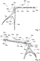
- FIG. 1 shows an isometric view of a surgical instrument 10a in an assembled state.
- the surgical instrument 10a is intended for interventions in a human body.
- the surgical instrument 10a is designed as a medical tissue punch.
- the surgical instrument 10a has a tool unit 20a.
- the tool unit 20a has a first tool element 22a.
- the tool unit 20a has a second tool element 24a.
- the second tool element 24a is movably mounted in the assembled state relative to the first tool element 22a in a translatory manner along a displacement axis 28a.
- the tool unit 20a has a first cutting element 54a.
- the tool unit 20a has at least one second cutting element 56a.
- the first tool element 22a has the first cutting element 54a.
- the first tool element 22a is integrally connected to the first cutting element 54a.
- the second tool element 24a has the second cutting element 56a.
- the second tool element 24a is integrally connected to the second cutting element 56a.
- the second cutting element 56a is movable in the installed state together with the second tool element 24a along the displacement axis 28a relative to the first cutting element 54a.
- the first cutting element 54a and the second cutting element 56a are formed as punching cutters.
- the first cutting element 54a is arranged at least substantially parallel to the second cutting element 56a.
- the first cutting element 54a has at least substantially a vertical arrangement relative to the first tool element 22a.
- the surgical instrument 10a has a manually operable actuator 70a.
- the first cutting element 54a and the second cutting element 56a are at least substantially open in the direction of the actuating unit 70a.
- the operating unit 70a is provided to operate the tool unit 20a.
- the operating unit 70a is provided to the second tool element 24a in the assembled state relative to the first tool element 22a to move.
- the actuating unit 70a has a first gripping element 74a.
- the actuating unit 70a has a second grip element 76a.
- the first grip element 74a and the second grip element 76a are arranged rotatably relative to one another.
- the first grip element 74a and the second grip element 76a are connected by means of a bolt.
- the first grip element 74a is connected to the second grip element 76a by means of a spring unit 78a of the actuation unit 70a.
- the spring unit 78a is provided to counteract an actuation of the grip elements 74a, 76a and return them to a starting position.
- the spring unit 78a has a first spring element 80a.
- the spring unit 78a has a second spring element 82a.
- the spring unit 78a is at least partially divisible into a first spring element 80a and into a second spring element 82a.
- the first spring element 80a is connected by means of a positive connection with the second spring element 82a.
- the actuating unit 70a is at least partially connected in one piece with the first tool element 22a.
- the second grip element 76a is integrally connected to the first tool element 22a (cf. Fig. 2 and 4 ).
- the actuating unit 70a has an actuating element 72a (cf. Fig. 2 . 3 and 4 ).
- the actuator 72a is integrally connected to the first handle member 74a.
- the actuator 72a is provided to move the second tool element 24a along the displacement axis 28a.
- the actuating element 72a is provided to move a coupling element 26a of the tool unit 20a along the displacement axis 28a (cf. Fig. 1, 2 and 3 ).
- the second tool element 24a is connected to the coupling element 26a.
- the second tool element 24a is riveted to the coupling element 26a.
- the coupling element 26a is movably mounted in the mounted state together with the second tool element 24a relative to the first tool element 22a in translation along the displacement axis 28a.
- the coupling element 26a is pivotally mounted on the second tool element 24a about at least one pivot axis 30a.
- the pivot axis 30a is formed at least substantially perpendicular to the displacement axis 28a.
- the pivot axis 30a is arranged at least substantially parallel to a main extension plane of the actuating unit 70a.
- the pivot axis 30a is at least substantially parallel to a main straight line of the second grip element 76a.
- the actuating element 72a is coupled to the coupling element 26a (cf. Fig. 1 ).
- the coupling element 26a releases the actuating element 72a in at least one second position relative to the second tool element 24a (cf. Fig. 2 and 3 ).
- the second tool element 24a is detachable from the first tool element 22a in this position.
- the coupling element 26a is pivoted in the second position to the outside.
- the coupling element 26a can be latched in the second position by means of a latching element 66a.
- the second tool element 24a has at least partially the latching element 66a.
- the second tool element 24a provides at least one contour 68a.
- the contour 68a forms the latching element 66a.
- the contour 68a is intended to allow a latching of the coupling element 26a in the second position.
- the coupling element 26a has a recess 48a.
- the recess 48a is provided to receive the actuator 72a.
- the coupling element 26a has a force transmission surface 50a.
- the power transmission surface 50a is intended to receive a direct contact with the actuator 72a.
- the force transmission surface 50a is provided for direct power transmission from the actuator 72a to the coupling element 26a.
- the surgical instrument 10a has at least one locking unit 90a, which locks the coupling element 26a in the first position.
- the locking unit 90a has a locking element 92a.
- the locking element 92a is pivotally mounted at least relative to the tool unit 20a.
- the locking element 92a is mounted on the first tool element 22a (cf. Fig. 3 ).
- the locking element 92a is riveted to the first tool element 22a.
- the locking element 92a provides at least one sliding guide surface 94a for the coupling element 26a.
- the locking element 92a has at least one leg 96a, 98a, 100a.
- the locking element 92a has three legs 96a, 98a, 100a.
- a first leg 96a of the locking element 92a is at least partially formed as a sliding guide surface 94a.
- a second leg 98a is connected to the first tool element 22a.
- the first leg 96a and the second leg 98a enclose an angle between 90 ° and 120 °.
- a third leg 100a is at least partially perpendicular to the first leg 96a.
- a main extension plane of the third leg 100a is at least partially perpendicular to the main extension plane of the actuator unit 70a.
- the third leg 100a is provided to stabilize the locking element 92a in a locked state (see FIG. Fig. 3 ).
- the tool unit 20a has at least one sliding bearing unit 32a.
- the sliding bearing unit 32a is provided to connect the second tool element 24a to the first tool element 22a in the first position.
- the second tool element 24a is slidably mounted on the first tool element 22a by means of the sliding bearing unit 32a.
- the sliding bearing unit 32a has at least one first sliding bearing element 34a.
- the sliding bearing unit 32a has at least one second sliding bearing element 46a (cf. Fig. 2 ).
- the first sliding bearing element 34a and the second sliding bearing element 46a are formed at least partially corresponding to one another.
- the sliding bearing element 34a is provided with the corresponding second sliding bearing element 46a for stabilizing the second tool element 24a relative to the first tool element 22a.
- the first slide bearing element 34a has at least one rail part 58a.
- the rail part 58a of the first sliding bearing element 34a is integrally connected to the first tool element 22a (see FIG. Fig. 4 ).
- the second sliding bearing element 46a is designed as a sliding part 60a.
- the sliding part 60a is in particular intended to slide on the rail part 58a (cf. Fig. 2 ).
- the sliding bearing unit 32a has a further first sliding bearing element 62a and a corresponding further second sliding bearing element 64a.
- the further sliding bearing elements 34a, 46a are in the form of special, mutually adapted shape contours of the first tool element 22a and the second tool element 24a. The shape contours at least partially provide a geometric engagement of the tool elements 22a, 24a.
- the sliding bearing unit 32a is at least partially formed integrally with the locking unit 90a.
- the sliding bearing unit 32a is at least partially formed integrally with the locking element 92a.
- the sliding guide surface 94a of the locking member 92a is also part of the sliding bearing unit 32a.
- the rail part 58a of the sliding bearing element 34a has a railless part (cf. Fig. 4 ).
- the second tool element 24a is detachable from the first tool element 22a by a movement along the displacement axis 28a.
- the second tool element 24a is moved in the direction of the actuating unit 70a.
- the sliding part 60a of the sliding bearing element 46a is guided in moving the second tool element 24a relative to the first tool element 22a in the railless part.
- a bearing of the sliding bearing element 46a is canceled in the railless part.
- the sliding bearing unit 32a supports the coupling element 26a in the first position in a sliding manner on the first tool element 22a.
- the sliding bearing unit 32a has a guide part 44a connected to the coupling element 26a (cf. Fig. 5 ).
- the guide part 44a is provided for stabilizing the coupling element 26a.
- the guide member 44a is provided to guide the second tool member 24a.
- the guide part 44a forms a spring 40a for a tongue and groove connection.
- the first tool element 22a has a groove 52a for receiving the guide part 44a.
- the groove 52a is provided to allow sliding of the guide member 44a.
- the first tool element 22a has an opening 36a (cf. Fig. 3 ).
- the opening 36a is provided to at least partially release the guide part 44a when pivoting the coupling element 26a from the first position to the second position.
- the coupling element 26a Upon disassembly of the surgical instrument 10a, the coupling element 26a is transferred from the first position to the second position relative to the second tool element 24a for releasing the actuating element 72a.
- the locking element 92a In a first method step, the locking element 92a is moved. The locking element 92a is rotated. The locking element 92a releases the coupling element 26a.
- the coupling element 26a is moved about the pivot axis 30a. The guide member 44a is guided on pivoting from the first position of the coupling element 26a to the second position of the coupling element 26a from the opening 36a.
- the second tool element 24a is displaced relative to the first tool element 22a.
- the second tool element 24a is displaced at least substantially in the direction of the actuating unit 70a.
- the second tool element 24a is displaced along the displacement axis 28a.
- a storage of the sliding bearing unit 32a is at least substantially canceled.
- the second tool element 24a is released from the first tool element 22a.
- the second tool element 24a is pushed onto the first tool element 22a in a first method step.
- the sliding bearing unit 32a at least partially connects the first tool element 22a with the second tool element 24a.
- the coupling element 26a is moved from the second position to the first position.
- the guide member 44a is passed through the opening 36a.
- the locking element 92a is pivoted back from the second position of the coupling element 26a to the first position of the coupling element 26a.
- the locking element 92a prevents pivoting of the coupling element 26a.
- FIG. 6-11 two further embodiments of the invention are shown.
- the following descriptions and the drawings are essentially limited to the differences between the exemplary embodiments, with reference in principle to the same reference components, in particular with respect to components with the same reference numerals, to the drawings and / or the description of the other embodiments, in particular Fig. 1-5 , can be referenced.
- To distinguish the embodiments of the letter a is the reference numerals of the embodiment in the Fig. 1-5 readjusted.
- the letter a is replaced by the letters b and c.
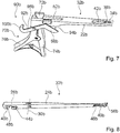
- FIG. 6-8 another surgical instrument 10b is shown.
- the surgical instrument 10b differs from the surgical instrument 10a substantially by an opening direction of a tool unit 20b.
- a second tool element 24b of the tool unit 20b is at least substantially rod-shaped (cf. Fig. 8 ).
- the tool unit 20b has a first cutting element 54b.
- the tool unit 20b has a second cutting element 56b.
- the first cutting element 54b is integrally formed with a first tool element 22b of the tool unit 20b.
- the second cutting element 56b is integrally formed with the second tool element 24b.
- the first cutting element 54b and the second cutting element 56b define an opening. The opening is provided to guide an object to be processed between the first cutting element 54b and the second cutting element 56b.
- the first cutting element 54b is arranged at least substantially parallel to the second cutting element 56b.
- the first cutting element 54b has an angle between 110 ° and 130 ° relative to the first tool element 22b.
- the tool unit 20b has a sliding bearing unit 32b.
- the sliding bearing unit 32b has at least one first sliding bearing element 34b (cf. Fig. 7 ).
- the sliding bearing unit 32b has at least one second sliding bearing element 46b (cf. Fig. 8 ).
- the first slide bearing element 34b is at least partially formed as a groove 38b.
- the second sliding bearing element 46b is at least partially designed as a spring 40b.
- the first sliding bearing member 34b and the second sliding bearing member 46b provide a tongue and groove connection.
- the spring-groove connection is intended to allow sliding of the second tool element 24b relative to the first tool element 22b.
- the sliding bearing unit 32b has a further groove 42b.
- the further groove 42b is provided for releasing the second slide bearing element 46b.
- the further groove 42b is provided for solving the tongue and groove connection.
- the further groove 42b immediately adjoins the groove 38b.
- the further groove 42b is at least 30% wider than the groove 38b.
- the surgical instrument 10c has a locking unit 90c with a locking element 92c.
- the locking element 92c is mounted on a coupling element 26c of a tool unit 20c (cf. Fig. 10 ).
- the locking element 92c is riveted to the coupling element 26c.
- the locking element 92c is movably mounted in a second position of the coupling element 26c relative to a second tool element 24c of the tool unit 20c along a displacement axis 28c.
- a main extension straight line of the locking element 92c is, at least in a first position of the coupling element 26c relative to the second tool element 24c, at least substantially parallel to the displacement axis 28c.
- the locking element 92c at least partially encloses an actuating element 72c of an actuating unit 60c.
- a pivot axis of the locking element 92c is aligned perpendicular to a pivot axis 30c of the coupling element 26c.
- the pivot axis of the locking element 92c is in the first position perpendicular to a main plane of extension of the actuating unit 70c.
- the tool unit 20c has a first cutting element 54c.
- the tool unit 20c has a second cutting element 56c.
- the first cutting element 54 c and the second cutting element 56 c are according to the second embodiment, which in the Figures 6-9 is shown aligned.
Landscapes
- Health & Medical Sciences (AREA)
- Surgery (AREA)
- Life Sciences & Earth Sciences (AREA)
- Medical Informatics (AREA)
- Animal Behavior & Ethology (AREA)
- Engineering & Computer Science (AREA)
- Biomedical Technology (AREA)
- Heart & Thoracic Surgery (AREA)
- Veterinary Medicine (AREA)
- Molecular Biology (AREA)
- Nuclear Medicine, Radiotherapy & Molecular Imaging (AREA)
- General Health & Medical Sciences (AREA)
- Public Health (AREA)
- Oral & Maxillofacial Surgery (AREA)
- Dentistry (AREA)
- Orthopedic Medicine & Surgery (AREA)
- Ophthalmology & Optometry (AREA)
- Pathology (AREA)
- Surgical Instruments (AREA)
Applications Claiming Priority (1)
| Application Number | Priority Date | Filing Date | Title |
|---|---|---|---|
| DE102017116935.0A DE102017116935A1 (de) | 2017-07-26 | 2017-07-26 | Chirurgisches Instrument |
Publications (2)
| Publication Number | Publication Date |
|---|---|
| EP3434207A1 true EP3434207A1 (fr) | 2019-01-30 |
| EP3434207B1 EP3434207B1 (fr) | 2021-09-22 |
Family
ID=63012847
Family Applications (1)
| Application Number | Title | Priority Date | Filing Date |
|---|---|---|---|
| EP18184347.5A Active EP3434207B1 (fr) | 2017-07-26 | 2018-07-19 | Instrument chirurgical |
Country Status (3)
| Country | Link |
|---|---|
| US (1) | US10918405B2 (fr) |
| EP (1) | EP3434207B1 (fr) |
| DE (1) | DE102017116935A1 (fr) |
Families Citing this family (5)
| Publication number | Priority date | Publication date | Assignee | Title |
|---|---|---|---|---|
| USD901689S1 (en) * | 2017-08-11 | 2020-11-10 | Karl Storz Se & Co. Kg | Bone punch |
| USD884173S1 (en) * | 2017-08-11 | 2020-05-12 | Karl Storz Se & Co. Kg | Bone punch |
| USD901688S1 (en) * | 2018-07-19 | 2020-11-10 | Karl Storz Se & Co. Kg | Bone punch |
| USD914210S1 (en) * | 2019-09-20 | 2021-03-23 | Gabriel Koros | Medical rongeur |
| FR3109718B1 (fr) * | 2020-04-30 | 2022-04-29 | Satt Axlr | Mécanisme de manipulation d’un instrument chirurgical |
Citations (1)
| Publication number | Priority date | Publication date | Assignee | Title |
|---|---|---|---|---|
| EP1302168A1 (fr) * | 2001-10-10 | 2003-04-16 | CODMAN & SHURTLEFF, INC. | Pince-Gouge chirurgicale avec dispositif d'écoulement |
Family Cites Families (8)
| Publication number | Priority date | Publication date | Assignee | Title |
|---|---|---|---|---|
| US5961531A (en) * | 1998-05-13 | 1999-10-05 | Kmedic, Inc. | Convertible rongeur |
| US6685710B2 (en) * | 2001-10-10 | 2004-02-03 | Codman & Shurtleff, Inc. | Rongeur with detachable crossbar |
| US20060189995A1 (en) * | 2005-02-22 | 2006-08-24 | Zimmer Spine, Inc. | Rongeur that disassembles for cleaning |
| DE102006012754B4 (de) * | 2006-03-17 | 2020-07-30 | Karl Storz Se & Co. Kg | Chirurgisches Instrument |
| DE202009002433U1 (de) * | 2009-02-20 | 2009-04-30 | Rebstock Instruments Gmbh | Chirurgisches Instrument |
| DE202009017555U1 (de) * | 2009-12-23 | 2010-04-01 | Medi-Plus Instrumente Gmbh | Schiebeschaftinstrument |
| US8801714B1 (en) * | 2011-02-02 | 2014-08-12 | Vikon Surgical, Llc | Surgical rongeur |
| DE202015006833U1 (de) * | 2015-09-29 | 2015-10-22 | Christoph Zepf | Knochenstanze mit unverlierbarem Stanzschieber |
-
2017
- 2017-07-26 DE DE102017116935.0A patent/DE102017116935A1/de not_active Withdrawn
-
2018
- 2018-07-19 EP EP18184347.5A patent/EP3434207B1/fr active Active
- 2018-07-24 US US16/043,720 patent/US10918405B2/en active Active
Patent Citations (1)
| Publication number | Priority date | Publication date | Assignee | Title |
|---|---|---|---|---|
| EP1302168A1 (fr) * | 2001-10-10 | 2003-04-16 | CODMAN & SHURTLEFF, INC. | Pince-Gouge chirurgicale avec dispositif d'écoulement |
Also Published As
| Publication number | Publication date |
|---|---|
| US10918405B2 (en) | 2021-02-16 |
| DE102017116935A1 (de) | 2019-01-31 |
| US20190029704A1 (en) | 2019-01-31 |
| EP3434207B1 (fr) | 2021-09-22 |
Similar Documents
| Publication | Publication Date | Title |
|---|---|---|
| EP3434207B1 (fr) | Instrument chirurgical | |
| EP2510888B1 (fr) | Dispositif de manipulation pour un instrument de chirurgie micro-invasive | |
| EP2249715B1 (fr) | Instrument chirurgical démontable | |
| DE10121305A1 (de) | Chirurgisches Instrument | |
| DE102018115435A1 (de) | Trokarhalterung | |
| EP1054636A1 (fr) | Poignee pour instrument medical | |
| EP2904978B1 (fr) | Rétracteur et procédé de commande | |
| EP3351191B1 (fr) | Instrument chirurgical, en particulier pour la neurochirurgie | |
| DE69822305T2 (de) | Klemmvorrrichtung , insbesondere eine biopsiezange | |
| EP2674116A1 (fr) | Pièce de saisie et de retenue d'outil pour un outil médical, en particulier chirurgical | |
| EP0159453B1 (fr) | Instrument chirurgical avec poignée | |
| EP2613726B1 (fr) | Instrument chirurgical | |
| EP2170184A2 (fr) | Instrument chirurgical | |
| EP1750599B9 (fr) | Partie de prehension d'un instrument chirurgical | |
| DE4417349A1 (de) | Vorrichtung zum Aufschneiden und Entfernen von Ringen | |
| DE10341561B4 (de) | Medizinisches Gerät | |
| DE202013100819U1 (de) | Skalpellhalter | |
| DE202016002850U1 (de) | Chirurgisches Handinstrument | |
| DE102012110260B4 (de) | Betätigungsgriff für ein mikrochirurgisches Instrument | |
| WO1999009878A1 (fr) | Endoscope chirurgical | |
| DE102021124291A1 (de) | Chirurgisches Instrument | |
| DE29610479U1 (de) | Medizinisches Instrument | |
| DE202009017555U1 (de) | Schiebeschaftinstrument | |
| DE102013005874A1 (de) | Griffstück für ein chirurgisches lnstrument | |
| DE202007000427U1 (de) | Chirurgischer Haltegriff und chirurgisches Instrument |
Legal Events
| Date | Code | Title | Description |
|---|---|---|---|
| PUAI | Public reference made under article 153(3) epc to a published international application that has entered the european phase |
Free format text: ORIGINAL CODE: 0009012 |
|
| STAA | Information on the status of an ep patent application or granted ep patent |
Free format text: STATUS: THE APPLICATION HAS BEEN PUBLISHED |
|
| AK | Designated contracting states |
Kind code of ref document: A1 Designated state(s): AL AT BE BG CH CY CZ DE DK EE ES FI FR GB GR HR HU IE IS IT LI LT LU LV MC MK MT NL NO PL PT RO RS SE SI SK SM TR |
|
| AX | Request for extension of the european patent |
Extension state: BA ME |
|
| STAA | Information on the status of an ep patent application or granted ep patent |
Free format text: STATUS: REQUEST FOR EXAMINATION WAS MADE |
|
| 17P | Request for examination filed |
Effective date: 20190411 |
|
| RBV | Designated contracting states (corrected) |
Designated state(s): AL AT BE BG CH CY CZ DE DK EE ES FI FR GB GR HR HU IE IS IT LI LT LU LV MC MK MT NL NO PL PT RO RS SE SI SK SM TR |
|
| STAA | Information on the status of an ep patent application or granted ep patent |
Free format text: STATUS: EXAMINATION IS IN PROGRESS |
|
| 17Q | First examination report despatched |
Effective date: 20201221 |
|
| GRAP | Despatch of communication of intention to grant a patent |
Free format text: ORIGINAL CODE: EPIDOSNIGR1 |
|
| STAA | Information on the status of an ep patent application or granted ep patent |
Free format text: STATUS: GRANT OF PATENT IS INTENDED |
|
| INTG | Intention to grant announced |
Effective date: 20210608 |
|
| GRAS | Grant fee paid |
Free format text: ORIGINAL CODE: EPIDOSNIGR3 |
|
| GRAA | (expected) grant |
Free format text: ORIGINAL CODE: 0009210 |
|
| STAA | Information on the status of an ep patent application or granted ep patent |
Free format text: STATUS: THE PATENT HAS BEEN GRANTED |
|
| AK | Designated contracting states |
Kind code of ref document: B1 Designated state(s): AL AT BE BG CH CY CZ DE DK EE ES FI FR GB GR HR HU IE IS IT LI LT LU LV MC MK MT NL NO PL PT RO RS SE SI SK SM TR |
|
| REG | Reference to a national code |
Ref country code: GB Ref legal event code: FG4D Free format text: NOT ENGLISH |
|
| REG | Reference to a national code |
Ref country code: DE Ref legal event code: R096 Ref document number: 502018007146 Country of ref document: DE |
|
| REG | Reference to a national code |
Ref country code: IE Ref legal event code: FG4D Free format text: LANGUAGE OF EP DOCUMENT: GERMAN |
|
| REG | Reference to a national code |
Ref country code: CH Ref legal event code: EP Ref country code: AT Ref legal event code: REF Ref document number: 1431689 Country of ref document: AT Kind code of ref document: T Effective date: 20211015 |
|
| REG | Reference to a national code |
Ref country code: LT Ref legal event code: MG9D |
|
| REG | Reference to a national code |
Ref country code: NL Ref legal event code: MP Effective date: 20210922 |
|
| PG25 | Lapsed in a contracting state [announced via postgrant information from national office to epo] |
Ref country code: HR Free format text: LAPSE BECAUSE OF FAILURE TO SUBMIT A TRANSLATION OF THE DESCRIPTION OR TO PAY THE FEE WITHIN THE PRESCRIBED TIME-LIMIT Effective date: 20210922 Ref country code: FI Free format text: LAPSE BECAUSE OF FAILURE TO SUBMIT A TRANSLATION OF THE DESCRIPTION OR TO PAY THE FEE WITHIN THE PRESCRIBED TIME-LIMIT Effective date: 20210922 Ref country code: SE Free format text: LAPSE BECAUSE OF FAILURE TO SUBMIT A TRANSLATION OF THE DESCRIPTION OR TO PAY THE FEE WITHIN THE PRESCRIBED TIME-LIMIT Effective date: 20210922 Ref country code: RS Free format text: LAPSE BECAUSE OF FAILURE TO SUBMIT A TRANSLATION OF THE DESCRIPTION OR TO PAY THE FEE WITHIN THE PRESCRIBED TIME-LIMIT Effective date: 20210922 Ref country code: LT Free format text: LAPSE BECAUSE OF FAILURE TO SUBMIT A TRANSLATION OF THE DESCRIPTION OR TO PAY THE FEE WITHIN THE PRESCRIBED TIME-LIMIT Effective date: 20210922 Ref country code: BG Free format text: LAPSE BECAUSE OF FAILURE TO SUBMIT A TRANSLATION OF THE DESCRIPTION OR TO PAY THE FEE WITHIN THE PRESCRIBED TIME-LIMIT Effective date: 20211222 Ref country code: NO Free format text: LAPSE BECAUSE OF FAILURE TO SUBMIT A TRANSLATION OF THE DESCRIPTION OR TO PAY THE FEE WITHIN THE PRESCRIBED TIME-LIMIT Effective date: 20211222 |
|
| PG25 | Lapsed in a contracting state [announced via postgrant information from national office to epo] |
Ref country code: LV Free format text: LAPSE BECAUSE OF FAILURE TO SUBMIT A TRANSLATION OF THE DESCRIPTION OR TO PAY THE FEE WITHIN THE PRESCRIBED TIME-LIMIT Effective date: 20210922 Ref country code: GR Free format text: LAPSE BECAUSE OF FAILURE TO SUBMIT A TRANSLATION OF THE DESCRIPTION OR TO PAY THE FEE WITHIN THE PRESCRIBED TIME-LIMIT Effective date: 20211223 |
|
| PG25 | Lapsed in a contracting state [announced via postgrant information from national office to epo] |
Ref country code: IS Free format text: LAPSE BECAUSE OF FAILURE TO SUBMIT A TRANSLATION OF THE DESCRIPTION OR TO PAY THE FEE WITHIN THE PRESCRIBED TIME-LIMIT Effective date: 20220122 Ref country code: SK Free format text: LAPSE BECAUSE OF FAILURE TO SUBMIT A TRANSLATION OF THE DESCRIPTION OR TO PAY THE FEE WITHIN THE PRESCRIBED TIME-LIMIT Effective date: 20210922 Ref country code: RO Free format text: LAPSE BECAUSE OF FAILURE TO SUBMIT A TRANSLATION OF THE DESCRIPTION OR TO PAY THE FEE WITHIN THE PRESCRIBED TIME-LIMIT Effective date: 20210922 Ref country code: PT Free format text: LAPSE BECAUSE OF FAILURE TO SUBMIT A TRANSLATION OF THE DESCRIPTION OR TO PAY THE FEE WITHIN THE PRESCRIBED TIME-LIMIT Effective date: 20220124 Ref country code: PL Free format text: LAPSE BECAUSE OF FAILURE TO SUBMIT A TRANSLATION OF THE DESCRIPTION OR TO PAY THE FEE WITHIN THE PRESCRIBED TIME-LIMIT Effective date: 20210922 Ref country code: NL Free format text: LAPSE BECAUSE OF FAILURE TO SUBMIT A TRANSLATION OF THE DESCRIPTION OR TO PAY THE FEE WITHIN THE PRESCRIBED TIME-LIMIT Effective date: 20210922 Ref country code: ES Free format text: LAPSE BECAUSE OF FAILURE TO SUBMIT A TRANSLATION OF THE DESCRIPTION OR TO PAY THE FEE WITHIN THE PRESCRIBED TIME-LIMIT Effective date: 20210922 Ref country code: EE Free format text: LAPSE BECAUSE OF FAILURE TO SUBMIT A TRANSLATION OF THE DESCRIPTION OR TO PAY THE FEE WITHIN THE PRESCRIBED TIME-LIMIT Effective date: 20210922 Ref country code: CZ Free format text: LAPSE BECAUSE OF FAILURE TO SUBMIT A TRANSLATION OF THE DESCRIPTION OR TO PAY THE FEE WITHIN THE PRESCRIBED TIME-LIMIT Effective date: 20210922 Ref country code: AL Free format text: LAPSE BECAUSE OF FAILURE TO SUBMIT A TRANSLATION OF THE DESCRIPTION OR TO PAY THE FEE WITHIN THE PRESCRIBED TIME-LIMIT Effective date: 20210922 |
|
| REG | Reference to a national code |
Ref country code: DE Ref legal event code: R097 Ref document number: 502018007146 Country of ref document: DE |
|
| PG25 | Lapsed in a contracting state [announced via postgrant information from national office to epo] |
Ref country code: DK Free format text: LAPSE BECAUSE OF FAILURE TO SUBMIT A TRANSLATION OF THE DESCRIPTION OR TO PAY THE FEE WITHIN THE PRESCRIBED TIME-LIMIT Effective date: 20210922 |
|
| PLBE | No opposition filed within time limit |
Free format text: ORIGINAL CODE: 0009261 |
|
| STAA | Information on the status of an ep patent application or granted ep patent |
Free format text: STATUS: NO OPPOSITION FILED WITHIN TIME LIMIT |
|
| 26N | No opposition filed |
Effective date: 20220623 |
|
| PG25 | Lapsed in a contracting state [announced via postgrant information from national office to epo] |
Ref country code: SI Free format text: LAPSE BECAUSE OF FAILURE TO SUBMIT A TRANSLATION OF THE DESCRIPTION OR TO PAY THE FEE WITHIN THE PRESCRIBED TIME-LIMIT Effective date: 20210922 |
|
| PG25 | Lapsed in a contracting state [announced via postgrant information from national office to epo] |
Ref country code: MC Free format text: LAPSE BECAUSE OF FAILURE TO SUBMIT A TRANSLATION OF THE DESCRIPTION OR TO PAY THE FEE WITHIN THE PRESCRIBED TIME-LIMIT Effective date: 20210922 |
|
| REG | Reference to a national code |
Ref country code: CH Ref legal event code: PL |
|
| REG | Reference to a national code |
Ref country code: BE Ref legal event code: MM Effective date: 20220731 |
|
| PG25 | Lapsed in a contracting state [announced via postgrant information from national office to epo] |
Ref country code: LU Free format text: LAPSE BECAUSE OF NON-PAYMENT OF DUE FEES Effective date: 20220719 Ref country code: LI Free format text: LAPSE BECAUSE OF NON-PAYMENT OF DUE FEES Effective date: 20220731 Ref country code: CH Free format text: LAPSE BECAUSE OF NON-PAYMENT OF DUE FEES Effective date: 20220731 |
|
| PG25 | Lapsed in a contracting state [announced via postgrant information from national office to epo] |
Ref country code: BE Free format text: LAPSE BECAUSE OF NON-PAYMENT OF DUE FEES Effective date: 20220731 |
|
| P01 | Opt-out of the competence of the unified patent court (upc) registered |
Effective date: 20230527 |
|
| PG25 | Lapsed in a contracting state [announced via postgrant information from national office to epo] |
Ref country code: IE Free format text: LAPSE BECAUSE OF NON-PAYMENT OF DUE FEES Effective date: 20220719 |
|
| PG25 | Lapsed in a contracting state [announced via postgrant information from national office to epo] |
Ref country code: HU Free format text: LAPSE BECAUSE OF FAILURE TO SUBMIT A TRANSLATION OF THE DESCRIPTION OR TO PAY THE FEE WITHIN THE PRESCRIBED TIME-LIMIT; INVALID AB INITIO Effective date: 20180719 |
|
| PG25 | Lapsed in a contracting state [announced via postgrant information from national office to epo] |
Ref country code: SM Free format text: LAPSE BECAUSE OF FAILURE TO SUBMIT A TRANSLATION OF THE DESCRIPTION OR TO PAY THE FEE WITHIN THE PRESCRIBED TIME-LIMIT Effective date: 20210922 Ref country code: MK Free format text: LAPSE BECAUSE OF FAILURE TO SUBMIT A TRANSLATION OF THE DESCRIPTION OR TO PAY THE FEE WITHIN THE PRESCRIBED TIME-LIMIT Effective date: 20210922 Ref country code: CY Free format text: LAPSE BECAUSE OF FAILURE TO SUBMIT A TRANSLATION OF THE DESCRIPTION OR TO PAY THE FEE WITHIN THE PRESCRIBED TIME-LIMIT Effective date: 20210922 |
|
| REG | Reference to a national code |
Ref country code: AT Ref legal event code: MM01 Ref document number: 1431689 Country of ref document: AT Kind code of ref document: T Effective date: 20230719 |
|
| PG25 | Lapsed in a contracting state [announced via postgrant information from national office to epo] |
Ref country code: MT Free format text: LAPSE BECAUSE OF FAILURE TO SUBMIT A TRANSLATION OF THE DESCRIPTION OR TO PAY THE FEE WITHIN THE PRESCRIBED TIME-LIMIT Effective date: 20210922 |
|
| PG25 | Lapsed in a contracting state [announced via postgrant information from national office to epo] |
Ref country code: AT Free format text: LAPSE BECAUSE OF NON-PAYMENT OF DUE FEES Effective date: 20230719 |
|
| PG25 | Lapsed in a contracting state [announced via postgrant information from national office to epo] |
Ref country code: AT Free format text: LAPSE BECAUSE OF NON-PAYMENT OF DUE FEES Effective date: 20230719 |
|
| PGFP | Annual fee paid to national office [announced via postgrant information from national office to epo] |
Ref country code: DE Payment date: 20250728 Year of fee payment: 8 |
|
| PGFP | Annual fee paid to national office [announced via postgrant information from national office to epo] |
Ref country code: IT Payment date: 20250721 Year of fee payment: 8 |
|
| PGFP | Annual fee paid to national office [announced via postgrant information from national office to epo] |
Ref country code: GB Payment date: 20250722 Year of fee payment: 8 |
|
| PGFP | Annual fee paid to national office [announced via postgrant information from national office to epo] |
Ref country code: FR Payment date: 20250725 Year of fee payment: 8 |
|
| PG25 | Lapsed in a contracting state [announced via postgrant information from national office to epo] |
Ref country code: TR Free format text: LAPSE BECAUSE OF FAILURE TO SUBMIT A TRANSLATION OF THE DESCRIPTION OR TO PAY THE FEE WITHIN THE PRESCRIBED TIME-LIMIT Effective date: 20210922 |
|
| PGFP | Annual fee paid to national office [announced via postgrant information from national office to epo] |
Ref country code: AT Payment date: 20260410 Year of fee payment: 5 |