EP3434323B1 - Dispositif de stimulation électrique fonctionnelle sous l'eau - Google Patents
Dispositif de stimulation électrique fonctionnelle sous l'eau Download PDFInfo
- Publication number
- EP3434323B1 EP3434323B1 EP18186033.9A EP18186033A EP3434323B1 EP 3434323 B1 EP3434323 B1 EP 3434323B1 EP 18186033 A EP18186033 A EP 18186033A EP 3434323 B1 EP3434323 B1 EP 3434323B1
- Authority
- EP
- European Patent Office
- Prior art keywords
- stimulation
- electrodes
- electrode
- muscle
- movement
- Prior art date
- Legal status (The legal status is an assumption and is not a legal conclusion. Google has not performed a legal analysis and makes no representation as to the accuracy of the status listed.)
- Active
Links
Images


Classifications
-
- A—HUMAN NECESSITIES
- A61—MEDICAL OR VETERINARY SCIENCE; HYGIENE
- A61N—ELECTROTHERAPY; MAGNETOTHERAPY; RADIATION THERAPY; ULTRASOUND THERAPY
- A61N1/00—Electrotherapy; Circuits therefor
- A61N1/18—Applying electric currents by contact electrodes
- A61N1/32—Applying electric currents by contact electrodes alternating or intermittent currents
- A61N1/36—Applying electric currents by contact electrodes alternating or intermittent currents for stimulation
- A61N1/36014—External stimulators, e.g. with patch electrodes
-
- A—HUMAN NECESSITIES
- A61—MEDICAL OR VETERINARY SCIENCE; HYGIENE
- A61N—ELECTROTHERAPY; MAGNETOTHERAPY; RADIATION THERAPY; ULTRASOUND THERAPY
- A61N1/00—Electrotherapy; Circuits therefor
- A61N1/02—Details
- A61N1/04—Electrodes
- A61N1/0404—Electrodes for external use
- A61N1/0472—Structure-related aspects
- A61N1/048—Electrodes characterised by a specific connection between lead and electrode
-
- A—HUMAN NECESSITIES
- A61—MEDICAL OR VETERINARY SCIENCE; HYGIENE
- A61N—ELECTROTHERAPY; MAGNETOTHERAPY; RADIATION THERAPY; ULTRASOUND THERAPY
- A61N1/00—Electrotherapy; Circuits therefor
- A61N1/02—Details
- A61N1/04—Electrodes
- A61N1/0404—Electrodes for external use
- A61N1/0472—Structure-related aspects
- A61N1/0484—Garment electrodes worn by the patient
-
- A—HUMAN NECESSITIES
- A61—MEDICAL OR VETERINARY SCIENCE; HYGIENE
- A61N—ELECTROTHERAPY; MAGNETOTHERAPY; RADIATION THERAPY; ULTRASOUND THERAPY
- A61N1/00—Electrotherapy; Circuits therefor
- A61N1/18—Applying electric currents by contact electrodes
- A61N1/32—Applying electric currents by contact electrodes alternating or intermittent currents
- A61N1/36—Applying electric currents by contact electrodes alternating or intermittent currents for stimulation
- A61N1/36003—Applying electric currents by contact electrodes alternating or intermittent currents for stimulation of motor muscles, e.g. for walking assistance
Definitions
- the invention relates to a device and a system for sensory stimulation or generation of muscle movement in water by electrical stimulation of nerves and / or muscles, the device comprising a stimulator, at least one electrode for transmitting electrical pulses to the skin and at least one cable for connecting the Includes stimulator with the at least one electrode and these are designed to be watertight, the control device being configured to stimulate a swimming movement. Also disclosed are uses and methods for sensory stimulation or the generation of muscle movements in water by electrical stimulation of nerves and / or muscles.
- the invention is in the field of leisure or medical technology and can be used with particular advantage in rehabilitation medicine. Applications in other areas of medical technology and in particular sports technology are also conceivable.
- An injury to the spine with accompanying paralysis of the lower extremities in many cases means a severe restriction of physical activity and health for those affected. Depending on the level and severity of the injury, this often means a functional limitation of various bodily functions. In addition, physical inactivity due to the injury is often in stark contrast to the pre-injury condition, especially for young patients.
- a device for increasing the heat supply and removal is known, electrical pulses being applied by means of electrodes to increase the blood flow on the outer surface of the skin.
- a pulse generator is proposed which, in preferred embodiments, is enclosed in a watertight housing.
- Functional electrical stimulation (FES) by means of the electrodes for stimulating movement patterns is not disclosed.
- the object of the invention was to provide a device and a method which overcomes the disadvantages of the prior art.
- Another object of the invention was to provide devices or methods which are easy to use and lead to a great improvement in mobility.
- the invention relates to a device for generating muscle movement in water by electrical stimulation of nerves and / or muscles, comprising a stimulator with a voltage source and a control device, at least one electrode for attachment to a skin, and at least one cable which connects the stimulator to the skin Connects electrode, wherein the stimulator, the at least one electrode and the at least one cable are designed to be waterproof, the control device is configured to generate electrical pulses on the at least one electrode for transmission to the skin, and the control device is configured to stimulate a swimming movement.
- connections between stimulator, electrode and cable are also particularly preferably watertight.
- the device provides excellent training results for functional stimulation of muscle movement under water as swimming training.
- devices or methods were known which disclose FES for movement training outside the water.
- test persons preferably designate users of the device, which can preferably be people with or without physical movement restrictions.
- the advantageous applicability of the device for generating muscle movement in water by electrical stimulation of nerves and / or muscles is made possible according to the invention by the waterproof design of the stimulator, the at least one electrode and the cable.
- a stimulator preferably designates a device or a device for the controllable generation of electrical pulses.
- a stimulator preferably has a voltage source (which can also be referred to as a pulse-generating unit), which is regulated by a control device.
- the voltage source is preferably connected to a battery or an accumulator, as a result of which the stimulator can be operated on the body without a cable for an external energy source.
- Suitable batteries include, for example, alkaline-manganese batteries, zinc chloride batteries or zinc-carbon batteries. Suitable batteries are, for example, lithium-ion batteries, sodium-ion batteries or NiCd - nickel-cadmium batteries.
- Suitable pulse-generating units for FES are well known to the person skilled in the art.
- Commercially available products such as RehaMove3 Science from Hasomed GmbH can also be used to provide a voltage source for the generation of the electrical pulses.
- the pattern which is generated with the voltage source or pulse generating unit is determined by the control device.
- control device is preferably a processor, preferably a microprocessor or processor chip, an integrated circuit and / or a microcontroller, which is configured to regulate the current intensity, pulse width and stimulation frequency of the electrical pulses according to predetermined parameters.
- the predetermined parameters can be stored on a data memory of the control device, so that the stimulation takes place according to a defined pattern.
- the predefined values are already sent to the control device via a communication interface.
- the control device can be connected to an operating unit which, after selection by the user, transmits the parameters to the control device by means of a wired or wireless connection.
- the control device particularly preferably comprises a wireless communication interface, for example based on WLAN, Bluetooth or other communication protocols.
- the communication interfaces of the control device preferably have a receiver and transmitter unit, which enable wireless exchange via these communication protocols. Wireless communication is particularly preferred for the integration of mobile devices or smart devices.
- the device is characterized in that the stimulator as well as the cable and the electrodes are made watertight.
- watertight preferably means watertightness, which ensures that when the device is used completely below water there is no impairment of function for longer than 1 hour.
- the components are preferably watertight, at which the penetration value of water is below 50 ⁇ g / min, preferably below 30 ⁇ g / min, particularly preferably below 10 ⁇ g / min, provided that the device is preferably under water at a water depth of 1 m.
- the stimulator can be completely encased, for example, by a waterproof cover or cuff. It may also be preferred to enclose the stimulator in a watertight housing.
- the waterproof housing is preferably made of plastic, preferably transparent plastic.
- a plastic housing ensures a watertight casing of the stimulator without impeding the optional communication of the stimulator with a mobile terminal.
- the electrical pulses generated by the stimulator are applied to the skin via the at least one electrode.
- This can be bipolar.
- a counter electrode can be attached freely in the water, on the housing of the stimulator or also on the body.
- FES applications it is known for FES applications to preferably use surface electrodes which provide electrical contact across the skin.
- Suitable medical electrodes are well known and preferably designed to be flexible so as not to lose contact even when the human skin is moving.
- the standard electrodes used are, for example, reusable hydrogel electrodes with a textile coating on the top or silicone electrodes with typical sizes of 2-20 cm 2 .
- Chlorinated swimming water typically has an electrical conductivity of 2.5-3 mS / cm (milli Siemens per centimeter) and thus a resistance of approx. 330-400 ohms. Stimulation by means of such standard electrodes therefore leads to creeping currents and a short circuit between the electrodes.
- such standard electrodes could be sealed in a simple manner.
- the electrodes can be encased in a waterproof sleeve, with the aid of which the electrodes are attached to the skin.
- cuffs for the thigh for example, are suitable, which cover the electrodes in a watertight manner.
- the device is characterized in that the at least one electrode has been sealed watertight by means of a sprayable polymer solution.
- the sprayable polymer solution is preferably a mixture of a volatile solvent and a hydrophobic polymer, which can be sprayed on using known spraying techniques. After spraying on the electrode, the solvent evaporates, leaving a hydrophobic polymer layer on the electrode. This seals the electrode surprisingly well against the ingress of moisture and water.
- Suitable polymers are, for example, polyvinylpyrrolidone, nitrocellulose, ethylcellulose, poly (methyl acrylate-isobutene-monoisopropyl maleate or cyanoacrylates.
- the sprayable polymer solution is a spray plaster or a spray dressing.
- waterproof electrodes are used, which in the US 7697999 B2 are described and the content of which is hereby fully incorporated by reference.
- the preferred waterproof electrodes include one conductive flexible element with a top and a bottom, a connector in contact with the conductive flexible element for establishing an electrical connection with a stimulator, a non-conductive flexible film which is arranged over the top of the conductive flexible element, the non- conductive film has a larger dimension than the conductive flexible element, so that there is an overlap, and preferably a central adhesive for connecting the non-conductive flexible film to the conductive flexible element.
- the watertightness of the electrodes ensures that the electrodes continue to function after bathing, showering and swimming.
- the functional use of the electrodes in the device according to the invention in water ie the application of electrical impulses, is preferably a waterproof adhesive film, for example Tegaderm from 3M, applied over the connection of the electrode and the cable. This also ensures that the plug connection is watertight.
- a waterproof adhesive film for example Tegaderm from 3M
- An example of such a particularly preferred waterproof electrode is shown in Fig. 3 and the associated description.
- Waterproof electrodes with a surface area of the conductive element (for example, a metallic wire arrangement) of 10 cm 2 to 30 cm 2 have proven to be particularly advantageous for the FES under water.
- Dimensions for covering by a non-conductive outer film from 50 cm 2 - 130 cm 2 show excellent results in terms of waterproofness, without reducing the comfort.
- waterproof electrodes in the sense of the invention are electrodes which are conductive on one side and are non-conductive on the opposite side.
- the electrodes When using the device for FES under water, the electrodes are attached to the body with the conductive side. The side facing away from the body is not electrically conductive.
- a stimulation effect can be achieved which is comparable to electrodes that are designed to be completely waterproof.
- a watertight electrode is therefore preferably present if, when using the device for FES under water on a body, interference of water with the stimulation can be prevented.
- the embodiment of the electrodes, in which only one side is electrically conductive while the other side is not electrically conductive is particularly easy to use. In particular, excellent results can be achieved with conductive rubber or silicone electrodes.
- the device comprises waterproof cables for connecting the stimulator to the electrodes. Plugs or plug connections with which the cables are connected to the simulator and to the electrodes are also preferably designed to be watertight.
- the device is characterized in that the connection of the at least one electrode to the at least one cable takes place through a plug enclosed by a silicone tube.
- the sheathing by means of a silicone hose enables a releasable, watertight attachment, which ensures that the electrodes can be connected or disconnected in a simple manner.
- Other means such as sleeves or the like can also be used to seal the plug connections, but the silicone tube is particularly distinguished by flexibility, water resistance and handling.
- the aforementioned preferred embodiments made it possible to provide a particularly suitable FES device for underwater use, which is characterized by particularly waterproof stimulators, electrodes, cables and connections between them.
- electrical pulses can be reliably applied to the skin of a person under water, which lead to sensory stimulation or to the production of a muscle movement.
- the device is characterized in that the electrical pulses are mono- or biphasic and do not exceed an energy of 10 mJ, the pulses preferably having a current between 0-120 mA and a pulse width between 0 and 1000 ⁇ s.
- Monophasic electrical pulses preferably denote pulses of the same positive or negative amplitude, whereas biphasic pulses are characterized in that an inverted pulse of the same energy but of opposite amplitude follows a pulse.
- the distance between two electrical pulses describes the period or frequency of the electrical pulses.
- a pulse series is usually applied during the stimulation of a muscle. In order to generate a contraction of a muscle under water, for example, a stimulation duration after application of several pulses of 0.2-5 seconds has proven to be sufficient.
- the device comprises fastening means for positioning the at least one electrode (A) on the skin of a human leg above the quadriceps femoris muscle and / or the ischiocrural muscles, it being particularly preferred for the device to have at least two Includes electrodes and fasteners for positioning the at least two electrodes on the skin of each leg of a human above the quadriceps femoris muscle and / or the ischiocrural muscles.
- the fastening means define themselves functionally in order to enable the aforementioned positioning.
- the fastening means can be a cuff which is adapted to the size of a human thigh and thus enables the required positioning.
- the length of the cable between the stimulator and the electrode is also adapted to the positioning for the preferred embodiment.
- the fastening means for positioning the electrodes on the aforementioned muscles thus represent structural features which characterize the preferred embodiment of the device.
- the quadriceps femoris muscle (hereinafter also abbreviated as quadriceps) is a skeletal muscle consisting of four muscle heads on the front of the thigh.
- the electrode is preferably attached to this area. Stimulation of the muscle area leads to an extension of the knee joint.
- the ischiocrural muscles or hamstring muscles in the back ( hamstring ) is a group of muscles that leads to a knee flexion.
- the embodiment is particularly suitable for stimulating a paddle or punch movement of the legs, referred to as flutter kick in English.
- the inventors recognized that the stimulation to the flutter kick is excellent for swimming training based on FES. In contrast to, for example, a frog movement of the legs, locomotion and noticeable training success can be achieved significantly more reliably.
- the device is characterized in that the control device is configured to stimulate a swimming movement, preferably a cyclic paddle movement of the legs.
- the device is characterized in that the control device is configured to effect cyclically alternating stimulation of both legs by means of at least two electrodes, the cyclically alternating stimulation preferably taking place at a frequency between 0.2 Hz and 5 Hz.
- a cyclical alternating stimulation means that the stimulator first applies the electrical pulses for the muscle area of a leg in order to cause it to be stretched or flexed. A suitable electrical pulse is then applied to the other leg so that the alternating cyclical stimulation triggers a cyclic paddle movement ( flutter kick ).
- the frequency of the stimulation preferably denotes the frequency with which the legs are alternately stretched or flexed.
- a frequency of 1 Hz for example, stimulation of the muscle area of one leg for 0.5 seconds, followed by a pause of 0.5 seconds, during which the muscle area of the other leg is stimulated.
- both legs are cyclically alternately stimulated with a frequency of 1 Hz.
- the device is characterized in that the device comprises at least four electrodes and fastening means for positioning in each case at least two electrodes on the skin of one leg of a person above the quadriceps femoris muscle and the ischiocrural muscles.
- control device is preferably configured such that the at least two electrodes per leg of a person provide a cyclically alternating stimulation of the two antagonistic muscle parts and the two legs.
- Different stimulation patterns can be used for this. Due to the increased flexibility, the movement pattern can be adapted particularly well to the individual needs of the user in order to realize pleasant swimming movements.
- the device can be configured such that the stimulation of the quadriceps femoris muscle or the ischiocrural muscles is supplemented by a stimulation of the gluteus maximus muscle .
- the gluteus maximus muscle (Latin for "largest gluteus muscle") causes a stretching in the hip joint and stabilization of the thigh, which further supports the swimming movement.
- a device which has at least two electrodes and fastening means for positioning the electrodes on the skin of a human leg above the quadriceps femoris muscle, the ischiocrural muscles, preferably the biceps femoris muscle, and / or the lower leg muscles.
- control device is configured to stimulate a gait movement.
- a number of stimulation patterns for stimulating gait movement outside the water are known to those skilled in the art. Surprisingly, these stimulation patterns can largely be used under water and lead to the desired success.
- hip extensors ischiocrural muscles
- knee extensors quadriceps femoris muscle
- knee flexors biceps femoris muscle
- muscles of the lower leg can be cyclically stimulated. It is particularly preferred to cyclically stimulate all muscle parts, including hip extensors, knee extensors or flexors, and muscles of the lower leg. If necessary, only a subset of this muscle can be activated by stimulation. In patients with hemiparesis, it is usually sufficient to support only the affected leg.
- the initiation of the step can optionally take place through the painful stimulation of the sole of the foot.
- Cyclic or permanent stimulation on the trunk can be used to stabilize the trunk.
- Upper limb stimulation can affect the gait and that Support balance in the water further. All muscles are activated in certain gait phases. Suitable patterns can be determined, for example, from healthy EMG leads when walking in water. These patterns are preferably predefined by the control device, so that the patient adjusts their activity accordingly. Alternatively, the patient or a therapist can synchronize the stimulation manually, for example by means of a hand switch or operating device, with the patient's gait phases / events.
- the device is characterized in that it comprises an item of clothing in which the at least one electrode is positioned such that when the item of clothing is worn by a person, the electrodes on the skin of a leg preferably above the quadriceps femoris muscle and / or the ischiocrural muscles are present, it being particularly preferred that at least two electrodes are positioned in the item of clothing in such a way that when the item of clothing is worn by a person, the electrodes on the skin of one leg each preferably above the quadriceps femoris muscle and / or the ischiocrural muscles available.
- This embodiment is particularly suitable for stimulating a swimming movement, preferably a cyclic paddle movement of the legs.
- a device which is characterized in that it comprises a piece of clothing, the device fastening means for positioning the at least one electrode on the skin of a human leg above the quadriceps femoris muscle, the ischiocrural muscles, the biceps femoris muscle and / or the lower leg muscles comprises, wherein it is particularly preferred that the device comprises at least two electrodes and fastening means for positioning the at least two electrodes on the skin of one leg each of a human above the quadriceps femoris muscle, the ischiocrural muscles, the biceps femoris muscle and / or the lower leg muscles.
- This device is particularly suitable for stimulating gait movement.
- an electrode on the skin of a human leg are particularly suitable for test subjects who are paralyzed on one side. With the FES, paddle movement of the restricted leg can be effectively stimulated and synchronized with the movement of the healthy leg.
- the embodiments of two electrodes on the skin of each leg of a human are particularly suitable for test subjects paralyzed on both sides.
- both variants can advantageously be used depending on the training needs.
- the item of clothing can be a pair of pants or a swimsuit with additional sleeves for the arms. However, at least the buttocks and thighs are preferably covered by the item of clothing, so that the electrodes can be securely and comfortably positioned on the quadriceps femoris muscle or the ischiocrural muscles. In the event of a desired stimulation of the lower leg muscles, the item of clothing will preferably also cover these muscle parts.
- the relative positioning of the electrodes over the desired muscle areas in the item of clothing is predetermined by the human anatomy. Positioning is therefore standardized information, which a specialist can easily determine based on the size and shape of a piece of clothing.
- the electrodes can be positioned by sewing, gluing or other permanent or detachable connections between the electrodes and the item of clothing.
- the embodiment of the invention allows a particularly user-friendly, quick application, which also ensures a particularly reliable positioning of the electrodes on the desired muscle parts.
- the device is characterized in that, in addition to the aforementioned electrodes, it comprises at least two further electrodes and fastening means for positioning an electrode above the spinal cord and a counter electrode on the side or on the abdomen of a person, and the control device is configured by the two others Lead to stimulate the spinal cord.
- transcutaneous spinal cord stimulation pulse energies under water from 1.5 mJ to 3 mJ provide excellent results.
- Transcutaneous spinal cord stimulation has a spasticity-relieving, pain-suppressing and, on the other hand, it promotes blood circulation, which relaxes the test subjects' muscles. Transcutaneous spinal cord stimulation therefore supports stimulation of muscle movement, e.g. the quadriceps femoris muscle or the ischiocrural muscles, and leads to fluid movement patterns and a high level of well-being.
- the device is characterized in that it comprises buoyancy bodies or floating weights.
- Buoyancy bodies also known as floating bodies, are able to float on their own according to the Archimedean principle due to the displacement of water. Ie their own weight is lower, than the weight of water of the same volume.
- Floats are characterized by the fact that their weight is higher than the weight of water of the same volume.
- FES swimming training can advantageously be supported by attaching the buoyancy bodies to the body or extremities of the test subject.
- the dimensioning can be chosen by a person skilled in the art for this purpose.
- the device can comprise suitable fastening means, such as cuffs.
- the device is characterized in that it comprises at least one sensor and fastening means for attaching the sensor to an extremity or the trunk, the sensor measuring the muscle activity and / or the movement of the extremity or the trunk and the control device based the electrical pulses are generated on the measurement results.
- the movement measurement of the extremity can include a determination of the translation, inclination or acceleration.
- Suitable sensors are, for example, gyroscopes, acceleration sensors and others, piezoelectric or capacitive, in particular also as microelectromechanical systems (MEMS) or combinations thereof.
- MEMS microelectromechanical systems
- IMU Inertial measurement units
- IMU Inertial measurement units
- Electromyography is a technique used to record myoelectric signals. Myoelectric signals are generated by physiological changes in the state of the muscle fiber membrane. It is particularly about the voluntary muscle activation of functional movements.
- Surface EMGs and intramuscular (needle and fine wire) EMGs are known in the prior art for deriving the muscle action potentials. Surface EMGs are particularly preferred for the described device and do not lead to any impairment of the movement.
- the derived signals are amplified by amplifiers and transferred to an analog-to-digital converter (ADC) for evaluation.
- ADC analog-to-digital converter
- the Texas Instruments ADS1292 is suitable for this. This has two input channels. It is therefore possible to measure on two different muscles at the same time.
- an ADC with appropriate channel equipment is preferably selected. Voltage resolutions of more than 8 bits, preferably more than 16 bits, particularly preferably 24 bits or more are preferred for the ADC. A high resolution enables a better one Signal-to-noise ratio, which enables muscle activity to be determined more precisely.
- the preferred ADU ADS1292 is based on a delta-sigma modulation at 125 kHz, which makes it possible to sample muscle activity with a maximum frequency of 8 kHz. This simplifies the dimensioning of the anti-aliasing filter required for this.
- the component has a variable number of samples per second and it is possible to output data between 125 and 8000 samples per second.
- a right-leg drive (RLD) is integrated in the sensor. This uses an additional electrode to suppress mains hum.
- an IMU takes a direct measurement of the movement of the body parts.
- muscle activity By measuring muscle activity, its intention can also be determined, in addition to or independently of the movement actually carried out, and used for synchronous stimulation.
- the sensors can be attached to the arms and record their movement there, for example using an IMU.
- the evaluation of the data can take place in the control device itself or in a data processing device, an evaluation which is as simultaneous as possible is preferred in order to adapt the stimulation pattern to the arm movement almost simultaneously. Surprisingly, measuring the trunk for this purpose also gives excellent results.
- an FES of the quadriceps femoris muscle or the ischiocrural muscles to generate a paddle movement of the legs can be synchronized particularly reliably with the crawl movement of the arms.
- Excellent results are achieved if the stimulation of the muscle part of a leg is initiated as soon as the angle of inclination of the trunk is more than 10 °, preferably more than 15 ° and at the same time an angular velocity of more than 30 ° / s, particularly preferably more than, for the trunk movement 40 ° / s is determined.
- the device is characterized in that the device has a watertight control element, which allows control of the stimulation intensity and pattern of the electrical pulses.
- the control element can preferably be carried on the body so that the test person can set the stimulation intensity and frequency of the electrical pulses.
- the stimulation intensity preferably means the current strength, pulse width and frequency of the electrical pulses during a stimulation. The higher the current, pulse width and frequency of the electrical pulses, the greater the stimulation intensity, ie the more powerfully a muscle is stimulated, the faster it will tire.
- the stimulation pattern preferably means the pattern on which the desired movement pattern is based. For example, this can be a frequency for a cyclical alternating stimulation of the legs during a paddle movement. It can also be preferred that the type of a movement pattern, for example a swimming movement, can be selected by the operating device and that the specific execution of the respective movement pattern can be set by specifying the stimulation frequency or intensity.
- the operating device thus allows optimal consideration of individual needs, which can also depend on the perception of the day or the form of the day.
- the device is characterized in that the stimulator has a communication interface for a smart device, preferably a smartphone, a smartwatch and / or a tablet.
- a smart device preferably a smartphone, a smartwatch and / or a tablet.
- Both communication interfaces e.g. USB interface
- a wireless communication interface for example based on WLAN, Bluetooth or other radio standards
- the communication interface is preferably integrated in the control device and, accordingly, preferably has a receiver and transmitter unit which enable wireless exchange via communication protocols.
- the ability to integrate mobile end devices or smart devices, such as a smartphone, a smartwatch and / or a tablet via communication interfaces, increases user friendliness and the ability to adapt complex stimulation patterns to individual needs.
- data about training units can be recorded in the smart device. It is also possible to set up or compare with training plans so that suggestions for stimulation patterns or intensities can be automatically submitted.
- further data such as biomedical data (heart rate, fitness) recorded by the smart device, can also be included.
- the invention relates to a system comprising a device according to the invention or a preferred embodiment thereof, as well as a smart device and a data processing program which is installed on the smart device, characterized in that the data processing program permits control of the stimulation frequency or intensity.
- the data processing program is preferably an application software, or app for short.
- the app can preferably also record data on past training units and, if necessary, compare them with the training plans that have been created.
- the invention further relates to the use of a device according to the invention or a system or preferred embodiments thereof for generating sensory stimulation or muscle movement in water by electrical stimulation of nerves and / or muscles.
- the preferred technical features of the device or system disclosed apply equally to its use and methods derived therefrom and have the same advantageous effects there.
- the device for example, it was disclosed that it preferably comprises at least two electrodes for attachment above the quadriceps femoris muscle and / or the ischiocrural muscles, it being particularly preferred that the control device is configured for the cyclically alternating stimulation of muscle parts of both legs.
- the method which can be derived therefrom also allows a particularly effective generation of a paddle movement ( flutter kick ) of the legs.
- the uses and methods relate exclusively to the leisure or sports area and preferably exercise training for subjects who are not restricted in movement.
- the use and procedures develop special training successes, not only in terms of increasing muscle strength and endurance, but also in terms of learning or optimizing movement patterns, which can be comfortably conveyed by the FES applications.
- FIG 1 shows a schematic representation of a preferred embodiment of the device.
- the device comprises a waterproof stimulator with integrated control device (D) which is worn on the body during swimming and is connected to the body via one or more waterproof cables (F) and one or more waterproof electrodes (A).
- sensors (B) for measuring orientation, movement and / or muscle activity are attached to the lower leg and / or thigh or other parts of the body and can be used to control the stimulation.
- the data is transmitted via a cable or wirelessly to the stimulator (D) or to a smart device (E).
- a functional movement of the extremity can be generated by generating current pulses which are passed on to the extremities via the cable (F) and the electrodes (A) creates a propulsion of the body in the water.
- a smart device (E) smart device (smartphone / smartwatch / tablet) can be used, which exchanges data with the stimulator via wireless communication.
- FIG. 2 shows a schematic representation of a preferred embodiment of the stimulator.
- the stimulator consists of a high voltage source (H), a battery (G), a wireless charging device (I), a wireless communication device (J), a waterproof connector for the stimulation cable (K), a waterproof housing (L), a demultiplexer (M) and a waterproof control element (N).
- the integrated control device in the stimulator is not shown in the figure, but can be a microprocessor, for example.
- FIG. 3 shows a schematic representation of a preferred embodiment of a waterproof electrode.
- the preferred waterproof electrodes include a conductive flexible member having a top and a bottom, a connector in contact with the conductive flexible member for electrical connection to a stimulator, a non-conductive flexible sheet disposed over the top of the conductive flexible member is, wherein the non-conductive film has a larger dimension than the conductive flexible element, so that there is an overlap, and preferably a central adhesive for connecting the non-conductive flexible film to the conductive flexible element.
- the watertightness of the electrodes ensures that the electrodes continue to function after bathing, showering and swimming.
- the functional use of the electrodes in water ie the application of electrical pulses, would be impaired due to a non-watertight connector or plug connection for the cable.
- the waterproof adhesive film, Tegaderm from 3M was therefore applied over the connection between the electrode and the cable for use at the FES under water.
- FIG 4 shows a schematic representation of a preferred embodiment of a waterproof connector for wiring the electrode to the stimulator. This is shown for a 2 mm plug, although other plugs can also be used.
- the connector is connected to the stimulator via a silicone cable.
- a silicone hose is used to make the connection between the electrode and the cable watertight.
- the standard plugs of the commercially available FES stimulators are usually not waterproof. This means that water can also penetrate the connection from behind. This connection point can also be sealed by permanent gluing using shrink tubing or hot glue.
- FIG. 5 shows a preferred gate signal for a stimulation pattern to excite the quadriceps femoris muscle.
- T1 denotes the duration of stimulation for a muscle
- T2 the period between two stimulations of the quadriceps
- T3 the period between a cyclically alternating stimulation of the quadriceps of the left and right leg.
- T1, T2 and T3 can be adapted to the subject's swimming technique.
- other muscles such as the ischiocrural muscles (hamstring, knee flexor) or the gluteus maximus (hip extensor) muscle can be stimulated in the same way.
- Figure 6 shows experimental data of knee extension and flexion by stimulating the quadriceps femoris muscle and the ischiocrural muscles. Based on the stimulation pattern shown, three consecutive knee rashes could be generated.
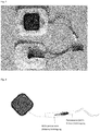
- Figure 7 shows underwater images of a stimulated crawl movement of a paralyzed subject (Th5, ASIA scale A). To support the crawl movement, floats were attached to the feet and antisynchronous stimulation of the left and right quadriceps femoris and the ischiocrural muscles was performed. A video analysis can be used to correlate experimental data on the movement with the stimulation pattern (cf. Figure 6 ).
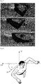
- Figure 8 shows a schematic representation of a preferred measurement of the movement of the trunk.
- an IMU sensor is attached to the subject's torso and the roll angle ⁇ of the torso is determined, where z E is the z axis of the world frame and z S and y S are the z and y axes of the intrinsic sensor frame.
- Figure 9 shows a schematic representation of a state machine for regulating the stimulation depending on the measured movement of the trunk.
- the state machine is implemented in stateflow, with each entry defining a singular action that is carried out for each time index k depending on the state.
- Figure 10 shows experimental data of a crawl movement by stimulating the quadriceps femoris muscle.
- Fig. 7 three photos are shown in the sagittal plane, which show the different states of the stimulation.
- the subject was asked not to swim with his arms to get a stable position for the angle record.
- underwater video data was recorded with a waterproof camera.
- the left knee angle was measured as in Fig. 6 shown.
- the cyclic stimulation of the quadriceps and hamstring can also be seen, which leads to a paddle movement of the legs. In combination with the crawling movement of the arms, an efficient swimming movement can be generated.
- the roll angle of the trunk is defined as the angle between the medio-lateral axis of the trunk and the horizontal plane, as in Fig. 5 shown.
- this angle typically varies periodically in the range of ⁇ 50 ° for professional swimmers and in the range of ⁇ 30 ° for inexperienced swimmers (cf. (Callaway et al., 2009; Bambalin et al., 2009)).
- An inertial sensor (IMU) is attached to the back of the fuselage in such a way that the intrinsic x-axis of the IMU is aligned with the longitudinal axis of the fuselage and the intrinsic y-axis of the IMU is medio-lateral to the right side of the IMU.
- the roll angle can be calculated using the following procedure.
- the orientation of the IMU is determined from the measured acceleration and the angular velocity.
- the algorithm proposed by Seel and Ruppin (2017) is used, which is a quaternion for each time index k q ⁇ s k delivers. This quaternion describes the orientation of the intrinsic sensor coordinate system S of the IMU in relation to a fixed reference coordinate system E with a vertical z-axis.
- the algorithm used is modular and the magnetometer-based correction described by Seel and Ruppin (2017) is not used because the azimuth information is not required.
- Fig. 10 the roll angle, the speed and the resulting stimulation currents of the experiment are shown. The subject was asked to crawl his arms and trunk. Whenever the stimulation criteria were met, the corresponding quadriceps muscle was stimulated.
- Example 3 Traininaserfolae by swimming training
- the subjects are over 18 years old and have paralysis of the lower extremities after spinal trauma.
- the study includes a land and a swimming phase.
- each of the 10 subjects carried out a four-week FES bike training. This includes at least three training sessions per week of at least 30 minutes on a RehaMove FES bicycle ergometer. At the beginning and end of this training phase, the thigh diameter and the maximum bike performance are recorded. The FES cycling training takes place during the land phase in order to build up a defined muscle mass of the paralyzed legs for the swimming attempt.
- FES cycling is reduced to a maximum of twice a week.
- swimming training begins with FES as well as without FES.
- the swim ratings consist of a strict ABBA pattern to eliminate the effect of fatigue.
- swimming tests with or without FES are separated by a 5-minute break.
- the test person is asked to swim a lane as quickly as possible, whereby the time is determined.
- the spasticity is determined using a Modified Ashworth Scale test.
- each subject fills out a questionnaire about their well-being and the usability of swimming training.
- a 5x5 cm electrode was placed on the back above the vertebral leads T11 and T12 and an electrically connected counter electrode (5 x 9cm or larger) on the stomach.
- the stimulation rate should be in the range of 30 to 50 Hz. In the experiments, 40 Hz was chosen as the frequency.
- biphasic pulses with a duration of 1 ms per phase were applied without a pause between the phases.
- the stimulation amplitude was chosen for the spinal cord stimulation in the first tests of the pilot study so that a visible increase in tone in the trunk and legs occurs, which leads to a stretching of the body.
Landscapes
- Health & Medical Sciences (AREA)
- Life Sciences & Earth Sciences (AREA)
- General Health & Medical Sciences (AREA)
- Engineering & Computer Science (AREA)
- Biomedical Technology (AREA)
- Nuclear Medicine, Radiotherapy & Molecular Imaging (AREA)
- Radiology & Medical Imaging (AREA)
- Animal Behavior & Ethology (AREA)
- Public Health (AREA)
- Veterinary Medicine (AREA)
- Heart & Thoracic Surgery (AREA)
- Biophysics (AREA)
- Physical Education & Sports Medicine (AREA)
- Electrotherapy Devices (AREA)
Claims (12)
- Dispositif de production d'un mouvement musculaire dans l'eau par stimulation électrique de nerfs et/ou de muscles, comprenant un stimulateur (D) avec une source de tension (H) et un dispositif de commande,
au moins une électrode (A) pour la fixation sur une peau,
et au moins un câble (F), lequel relie le stimulateur (D) à l'électrode (A), dans lequel le stimulateur (D), l'au moins une électrode (A) et l'au moins un câble (F) sont réalisés de manière étanche à l'eau et le dispositif de commande est configuré pour produire au niveau de l'au moins une électrode (A) des impulsions électriques pour la transmission sur la peau, dans lequel le dispositif de commande est configuré pour la stimulation d'un mouvement de natation. - Dispositif selon la revendication précédente
caractérisé en ce que
l'au moins une électrode (A) a été scellée étanche à l'eau au moyen d'un pansement à vaporiser et/ou d'un bandage à vaporiser et/ou
la liaison de l'au moins une électrode (A) à l'au moins un câble (F) se fait par un connecteur entouré par un tuyau en silicone. - Dispositif selon l'une quelconque des revendications précédentes,
caractérisé en ce que les impulsions électriques sont monophasées ou biphasées et ne dépassent pas une énergie de 10 mJ, dans lequel les impulsions présentent de préférence une intensité entre 0-120 mA et une largeur d'impulsion entre 0 et 1000 µs. - Dispositif selon l'une quelconque des revendications précédentes,
caractérisé en ce que le dispositif comprend des moyens de fixation pour le positionnement de l'au moins une électrode (A) sur la peau d'une jambe d'une personne au-dessus du musculus quadriceps femoris et/ou de la musculature ischiocrurale, dans lequel il est particulièrement préféré que le dispositif comprend au moins deux électrodes (A) ainsi que des moyens de fixation pour le positionnement des au moins deux électrodes (A) sur la peau respectivement d'une jambe d'une personne au-dessus du musculus quadriceps femoris et/ou de la musculature ischiocrurale. - Dispositif selon la revendication précédente,
Caractérisé en ce que le dispositif de commande est configuré pour la stimulation d'un mouvement de pale cyclique des jambes. - Dispositif selon la revendication précédente,
caractérisé en ce que le dispositif de commande est configuré pour provoquer par au moins deux électrodes (A), une stimulation cycliquement alternée des deux jambes, dans lequel la stimulation cycliquement alternée se fait de préférence avec une fréquence entre 0,5 Hz et 5 Hz. - Dispositif selon l'une quelconque des revendications précédentes,
caractérisé en ce que
le dispositif comprend un vêtement, dans lequel l'au moins une électrode est positionnée de sorte que lors du port du vêtement par une personne, les électrodes sont sur la peau d'une jambe de préférence au-dessus du musculus quadriceps femoris et/ou de la musculature ischiocrurale,
dans lequel il est particulièrement préféré qu'au moins deux électrodes (A) sont positionnées dans le vêtement de sorte que lors du port du vêtement par une personne les électrodes (A) sont sur la peau respectivement d'une jambe de préférence au-dessus du musculus quadriceps femoris et/ou de la musculature ischiocrurale. - Dispositif selon l'une quelconque des revendications précédentes,
caractérisé en ce que
le dispositif comprend des flotteurs ou des poids à fixer au niveau des extrémités d'une personne. - Dispositif selon l'une quelconque des revendications précédentes 4-8,
caractérisé en ce que
le dispositif comprend au moins deux autres électrodes (A) ainsi que des moyens de fixation pour le positionnement d'une électrode (A) au-dessus de la moelle épinière et d'une contre-électrode (A) latéralement ou sur le ventre d'une personne et le dispositif de commande est configuré pour provoquer une stimulation de la moelle épinière par les deux autres électrodes (A). - Dispositif selon l'une quelconque des revendications précédentes,
caractérisé en ce que le dispositif comprend au moins un capteur (B) ainsi que des moyens de fixation pour le montage du capteur au niveau d'une extrémité ou du torse, dans lequel le capteur (B) mesure l'activité musculaire et/ou le mouvement de l'extrémité ou du torse et le dispositif de commande génère les impulsions électriques sur la base des résultats de mesure. - Dispositif selon l'une quelconque des revendications précédentes,
caractérisé en ce que présente un élément de service étanche à l'eau, lequel permet une commande de l'intensité de stimulation et de la fréquence de stimulation des impulsions électriques. - Système comprenant
un dispositif selon l'une quelconque des revendications précédente,
un dispositif intelligent,
ainsi qu'un programme de traitement de données, lequel est installé sur le dispositif intelligent,
caractérisé en ce que
le programme de traitement de données permet une intensité de stimulation et fréquence de stimulation des impulsions électriques.
Applications Claiming Priority (2)
| Application Number | Priority Date | Filing Date | Title |
|---|---|---|---|
| DE102017007229 | 2017-07-29 | ||
| DE102018106634 | 2018-03-21 |
Publications (2)
| Publication Number | Publication Date |
|---|---|
| EP3434323A1 EP3434323A1 (fr) | 2019-01-30 |
| EP3434323B1 true EP3434323B1 (fr) | 2020-04-08 |
Family
ID=63079806
Family Applications (1)
| Application Number | Title | Priority Date | Filing Date |
|---|---|---|---|
| EP18186033.9A Active EP3434323B1 (fr) | 2017-07-29 | 2018-07-27 | Dispositif de stimulation électrique fonctionnelle sous l'eau |
Country Status (1)
| Country | Link |
|---|---|
| EP (1) | EP3434323B1 (fr) |
Families Citing this family (21)
| Publication number | Priority date | Publication date | Assignee | Title |
|---|---|---|---|---|
| DE102012013534B3 (de) | 2012-07-05 | 2013-09-19 | Tobias Sokolowski | Vorrichtung für repetitive Nervenstimulation zum Abbau von Fettgewebe mittels induktiver Magnetfelder |
| US11491342B2 (en) | 2015-07-01 | 2022-11-08 | Btl Medical Solutions A.S. | Magnetic stimulation methods and devices for therapeutic treatments |
| US20180001107A1 (en) | 2016-07-01 | 2018-01-04 | Btl Holdings Limited | Aesthetic method of biological structure treatment by magnetic field |
| US10695575B1 (en) | 2016-05-10 | 2020-06-30 | Btl Medical Technologies S.R.O. | Aesthetic method of biological structure treatment by magnetic field |
| US11266850B2 (en) | 2015-07-01 | 2022-03-08 | Btl Healthcare Technologies A.S. | High power time varying magnetic field therapy |
| US11253717B2 (en) | 2015-10-29 | 2022-02-22 | Btl Healthcare Technologies A.S. | Aesthetic method of biological structure treatment by magnetic field |
| US11464993B2 (en) | 2016-05-03 | 2022-10-11 | Btl Healthcare Technologies A.S. | Device including RF source of energy and vacuum system |
| US11247039B2 (en) | 2016-05-03 | 2022-02-15 | Btl Healthcare Technologies A.S. | Device including RF source of energy and vacuum system |
| US11534619B2 (en) | 2016-05-10 | 2022-12-27 | Btl Medical Solutions A.S. | Aesthetic method of biological structure treatment by magnetic field |
| US10583287B2 (en) | 2016-05-23 | 2020-03-10 | Btl Medical Technologies S.R.O. | Systems and methods for tissue treatment |
| US10556122B1 (en) | 2016-07-01 | 2020-02-11 | Btl Medical Technologies S.R.O. | Aesthetic method of biological structure treatment by magnetic field |
| US11141219B1 (en) | 2016-08-16 | 2021-10-12 | BTL Healthcare Technologies, a.s. | Self-operating belt |
| US12156689B2 (en) | 2019-04-11 | 2024-12-03 | Btl Medical Solutions A.S. | Methods and devices for aesthetic treatment of biological structures by radiofrequency and magnetic energy |
| US12558146B2 (en) | 2019-04-11 | 2026-02-24 | Btl Medical Solutions A.S. | Methods and devices for aesthetic treatment of biological structures by radiofrequency and magnetic energy |
| AU2020270557C1 (en) | 2019-04-11 | 2022-01-20 | Btl Medical Solutions A.S. | Methods and devices for aesthetic treatment of biological structures by radiofrequency and magnetic energy |
| BR112022022112A2 (pt) | 2020-05-04 | 2022-12-13 | Btl Healthcare Technologies As | Dispositivo para tratamento não assistido do paciente |
| US11878167B2 (en) | 2020-05-04 | 2024-01-23 | Btl Healthcare Technologies A.S. | Device and method for unattended treatment of a patient |
| DE102020132844B3 (de) | 2020-12-09 | 2022-05-19 | Protronic Innovative Steuerungselektronik Gmbh | Vorrichtung und Verfahren zur Muskelstimulation |
| WO2023062563A1 (fr) | 2021-10-13 | 2023-04-20 | Btl Medical Solutions A.S. | Dispositifs de traitement esthétique de structures biologiques par énergie radiofréquence et magnétique |
| US11896816B2 (en) | 2021-11-03 | 2024-02-13 | Btl Healthcare Technologies A.S. | Device and method for unattended treatment of a patient |
| US20260097225A1 (en) | 2024-10-08 | 2026-04-09 | Btl Medical Solutions A.S. | Devices and methods for application of a magnetic field to the nervous system |
Family Cites Families (6)
| Publication number | Priority date | Publication date | Assignee | Title |
|---|---|---|---|---|
| US5018521A (en) * | 1986-10-24 | 1991-05-28 | Campbell William P | Method of and apparatus for increased transfer of heat into or out of the body |
| US6745082B2 (en) | 2001-10-22 | 2004-06-01 | Jens Axelgaard | Current-controlling electrode with adjustable contact area |
| US7697999B2 (en) | 2003-02-06 | 2010-04-13 | Axelgaard Manufacturing Company, Ltd. | Moisture resistant electrode with edge protection |
| WO2014089331A1 (fr) * | 2012-12-06 | 2014-06-12 | Ossur Hf | Stimulation électrique pour dispositifs orthopédiques |
| WO2014143479A1 (fr) * | 2013-03-14 | 2014-09-18 | Birch Tree Medical, Inc. | Vêtement chauffé pour applications médicales |
| US9956393B2 (en) * | 2015-02-24 | 2018-05-01 | Elira, Inc. | Systems for increasing a delay in the gastric emptying time for a patient using a transcutaneous electro-dermal patch |
-
2018
- 2018-07-27 EP EP18186033.9A patent/EP3434323B1/fr active Active
Non-Patent Citations (1)
| Title |
|---|
| None * |
Also Published As
| Publication number | Publication date |
|---|---|
| EP3434323A1 (fr) | 2019-01-30 |
Similar Documents
| Publication | Publication Date | Title |
|---|---|---|
| EP3434323B1 (fr) | Dispositif de stimulation électrique fonctionnelle sous l'eau | |
| US11672982B2 (en) | Control system for movement reconstruction and/or restoration for a patient | |
| Kralj et al. | Enhancement of hemiplegic patient rehabilitation by means of functional electrical stimulation | |
| Crema et al. | A wearable multi-site system for NMES-based hand function restoration | |
| Szeto et al. | Electrocutaneous stimulation for sensory communication in rehabilitation engineering | |
| DE102015002565A1 (de) | System und Verfahren zur Steuerung von Stimulations-Impulsen | |
| EP3259016A2 (fr) | Dispositif, système et procédé de transmission de stimuli | |
| Popovic et al. | Functional electrical stimulation therapy: recovery of function following spinal cord injury and stroke | |
| US11027128B2 (en) | Device for non-invasive electrical stimulation of the spinal cord | |
| MXPA04010883A (es) | Un metodo y aparato para mejorar el desempeno neurofisiologico. | |
| CN105307719A (zh) | 局部神经刺激仪 | |
| Wiesener et al. | Supporting front crawl swimming in paraplegics using electrical stimulation: a feasibility study | |
| WO2014136852A1 (fr) | Dispositif de stimulation électrique | |
| Rossi et al. | An event-driven closed-loop system for real-time FES control | |
| Bhatia et al. | State of art: functional electrical stimulation (FES) | |
| Lynch et al. | Co-contraction of antagonist muscles during knee extension against gravity: Insights for functional electrical stimulation control design | |
| Irimia et al. | Controlling a FES-EXOSKELETON rehabilitation system by means of brain-computer interface | |
| Wiesener et al. | An inertial sensor-based trigger algorithm for functional electrical stimulation-assisted swimming in paraplegics | |
| McCabe et al. | Feasibility of combining gait robot and multichannel functional electrical stimulation with intramuscular electrodes. | |
| Hussein et al. | Muscle coordination in healthy subjects during floor walking and stair climbing in robot assisted gait training | |
| Santamaria et al. | A motor learning-based postural intervention with a robotic trunk support trainer to improve functional sitting in spinal cord injury: case report | |
| Wiesener et al. | Inertial-Sensor-Controlled Functional Electrical Stimulation for Swimming in Paraplegics: Enabling a Novel Hybrid Exercise Modality | |
| Spieker et al. | Motor and sensor recovery in a paraplegic by transcutaneous spinal cord stimulation in water | |
| Nishida et al. | bioSync: Wearable haptic I/O device for synchronous kinesthetic interaction | |
| Pinheiro et al. | Comparing spatially distributed and single electrode stimulation on individuals with spinal cord injury |
Legal Events
| Date | Code | Title | Description |
|---|---|---|---|
| PUAI | Public reference made under article 153(3) epc to a published international application that has entered the european phase |
Free format text: ORIGINAL CODE: 0009012 |
|
| STAA | Information on the status of an ep patent application or granted ep patent |
Free format text: STATUS: THE APPLICATION HAS BEEN PUBLISHED |
|
| AK | Designated contracting states |
Kind code of ref document: A1 Designated state(s): AL AT BE BG CH CY CZ DE DK EE ES FI FR GB GR HR HU IE IS IT LI LT LU LV MC MK MT NL NO PL PT RO RS SE SI SK SM TR |
|
| AX | Request for extension of the european patent |
Extension state: BA ME |
|
| STAA | Information on the status of an ep patent application or granted ep patent |
Free format text: STATUS: REQUEST FOR EXAMINATION WAS MADE |
|
| 17P | Request for examination filed |
Effective date: 20190724 |
|
| RBV | Designated contracting states (corrected) |
Designated state(s): AL AT BE BG CH CY CZ DE DK EE ES FI FR GB GR HR HU IE IS IT LI LT LU LV MC MK MT NL NO PL PT RO RS SE SI SK SM TR |
|
| RIC1 | Information provided on ipc code assigned before grant |
Ipc: A61N 1/04 20060101ALI20190905BHEP Ipc: A61N 1/36 20060101AFI20190905BHEP |
|
| GRAP | Despatch of communication of intention to grant a patent |
Free format text: ORIGINAL CODE: EPIDOSNIGR1 |
|
| STAA | Information on the status of an ep patent application or granted ep patent |
Free format text: STATUS: GRANT OF PATENT IS INTENDED |
|
| INTG | Intention to grant announced |
Effective date: 20191016 |
|
| GRAJ | Information related to disapproval of communication of intention to grant by the applicant or resumption of examination proceedings by the epo deleted |
Free format text: ORIGINAL CODE: EPIDOSDIGR1 |
|
| STAA | Information on the status of an ep patent application or granted ep patent |
Free format text: STATUS: REQUEST FOR EXAMINATION WAS MADE |
|
| GRAR | Information related to intention to grant a patent recorded |
Free format text: ORIGINAL CODE: EPIDOSNIGR71 |
|
| GRAS | Grant fee paid |
Free format text: ORIGINAL CODE: EPIDOSNIGR3 |
|
| STAA | Information on the status of an ep patent application or granted ep patent |
Free format text: STATUS: GRANT OF PATENT IS INTENDED |
|
| GRAA | (expected) grant |
Free format text: ORIGINAL CODE: 0009210 |
|
| STAA | Information on the status of an ep patent application or granted ep patent |
Free format text: STATUS: THE PATENT HAS BEEN GRANTED |
|
| INTC | Intention to grant announced (deleted) | ||
| AK | Designated contracting states |
Kind code of ref document: B1 Designated state(s): AL AT BE BG CH CY CZ DE DK EE ES FI FR GB GR HR HU IE IS IT LI LT LU LV MC MK MT NL NO PL PT RO RS SE SI SK SM TR |
|
| INTG | Intention to grant announced |
Effective date: 20200302 |
|
| REG | Reference to a national code |
Ref country code: CH Ref legal event code: EP Ref country code: AT Ref legal event code: REF Ref document number: 1253515 Country of ref document: AT Kind code of ref document: T Effective date: 20200415 |
|
| REG | Reference to a national code |
Ref country code: DE Ref legal event code: R096 Ref document number: 502018001140 Country of ref document: DE |
|
| REG | Reference to a national code |
Ref country code: IE Ref legal event code: FG4D Free format text: LANGUAGE OF EP DOCUMENT: GERMAN |
|
| REG | Reference to a national code |
Ref country code: CH Ref legal event code: PK Free format text: BERICHTIGUNGEN |
|
| REG | Reference to a national code |
Ref country code: DE Ref legal event code: R081 Ref document number: 502018001140 Country of ref document: DE Owner name: SENSORSTIM NEUROTECHNOLOGY GMBH, DE Free format text: FORMER OWNER: VOIGT, HANNO, 16356 AHRENSFELDE, DE |
|
| RAP2 | Party data changed (patent owner data changed or rights of a patent transferred) |
Owner name: SENSORSTIM NEUROTECHNOLOGY GMBH |
|
| RIN2 | Information on inventor provided after grant (corrected) |
Inventor name: VOIGT, HANNO |
|
| REG | Reference to a national code |
Ref country code: NL Ref legal event code: MP Effective date: 20200408 |
|
| REG | Reference to a national code |
Ref country code: LT Ref legal event code: MG4D |
|
| PG25 | Lapsed in a contracting state [announced via postgrant information from national office to epo] |
Ref country code: NO Free format text: LAPSE BECAUSE OF FAILURE TO SUBMIT A TRANSLATION OF THE DESCRIPTION OR TO PAY THE FEE WITHIN THE PRESCRIBED TIME-LIMIT Effective date: 20200708 Ref country code: GR Free format text: LAPSE BECAUSE OF FAILURE TO SUBMIT A TRANSLATION OF THE DESCRIPTION OR TO PAY THE FEE WITHIN THE PRESCRIBED TIME-LIMIT Effective date: 20200709 Ref country code: FI Free format text: LAPSE BECAUSE OF FAILURE TO SUBMIT A TRANSLATION OF THE DESCRIPTION OR TO PAY THE FEE WITHIN THE PRESCRIBED TIME-LIMIT Effective date: 20200408 Ref country code: IS Free format text: LAPSE BECAUSE OF FAILURE TO SUBMIT A TRANSLATION OF THE DESCRIPTION OR TO PAY THE FEE WITHIN THE PRESCRIBED TIME-LIMIT Effective date: 20200808 Ref country code: SE Free format text: LAPSE BECAUSE OF FAILURE TO SUBMIT A TRANSLATION OF THE DESCRIPTION OR TO PAY THE FEE WITHIN THE PRESCRIBED TIME-LIMIT Effective date: 20200408 Ref country code: NL Free format text: LAPSE BECAUSE OF FAILURE TO SUBMIT A TRANSLATION OF THE DESCRIPTION OR TO PAY THE FEE WITHIN THE PRESCRIBED TIME-LIMIT Effective date: 20200408 Ref country code: LT Free format text: LAPSE BECAUSE OF FAILURE TO SUBMIT A TRANSLATION OF THE DESCRIPTION OR TO PAY THE FEE WITHIN THE PRESCRIBED TIME-LIMIT Effective date: 20200408 Ref country code: PT Free format text: LAPSE BECAUSE OF FAILURE TO SUBMIT A TRANSLATION OF THE DESCRIPTION OR TO PAY THE FEE WITHIN THE PRESCRIBED TIME-LIMIT Effective date: 20200817 |
|
| REG | Reference to a national code |
Ref country code: AT Ref legal event code: PC Ref document number: 1253515 Country of ref document: AT Kind code of ref document: T Owner name: SENSORSTIM NEUROTECHNOLOGY GMBH, DE Effective date: 20200921 |
|
| PG25 | Lapsed in a contracting state [announced via postgrant information from national office to epo] |
Ref country code: BG Free format text: LAPSE BECAUSE OF FAILURE TO SUBMIT A TRANSLATION OF THE DESCRIPTION OR TO PAY THE FEE WITHIN THE PRESCRIBED TIME-LIMIT Effective date: 20200708 Ref country code: RS Free format text: LAPSE BECAUSE OF FAILURE TO SUBMIT A TRANSLATION OF THE DESCRIPTION OR TO PAY THE FEE WITHIN THE PRESCRIBED TIME-LIMIT Effective date: 20200408 Ref country code: LV Free format text: LAPSE BECAUSE OF FAILURE TO SUBMIT A TRANSLATION OF THE DESCRIPTION OR TO PAY THE FEE WITHIN THE PRESCRIBED TIME-LIMIT Effective date: 20200408 Ref country code: HR Free format text: LAPSE BECAUSE OF FAILURE TO SUBMIT A TRANSLATION OF THE DESCRIPTION OR TO PAY THE FEE WITHIN THE PRESCRIBED TIME-LIMIT Effective date: 20200408 |
|
| PG25 | Lapsed in a contracting state [announced via postgrant information from national office to epo] |
Ref country code: AL Free format text: LAPSE BECAUSE OF FAILURE TO SUBMIT A TRANSLATION OF THE DESCRIPTION OR TO PAY THE FEE WITHIN THE PRESCRIBED TIME-LIMIT Effective date: 20200408 |
|
| REG | Reference to a national code |
Ref country code: DE Ref legal event code: R097 Ref document number: 502018001140 Country of ref document: DE |
|
| PG25 | Lapsed in a contracting state [announced via postgrant information from national office to epo] |
Ref country code: ES Free format text: LAPSE BECAUSE OF FAILURE TO SUBMIT A TRANSLATION OF THE DESCRIPTION OR TO PAY THE FEE WITHIN THE PRESCRIBED TIME-LIMIT Effective date: 20200408 Ref country code: CZ Free format text: LAPSE BECAUSE OF FAILURE TO SUBMIT A TRANSLATION OF THE DESCRIPTION OR TO PAY THE FEE WITHIN THE PRESCRIBED TIME-LIMIT Effective date: 20200408 Ref country code: DK Free format text: LAPSE BECAUSE OF FAILURE TO SUBMIT A TRANSLATION OF THE DESCRIPTION OR TO PAY THE FEE WITHIN THE PRESCRIBED TIME-LIMIT Effective date: 20200408 Ref country code: EE Free format text: LAPSE BECAUSE OF FAILURE TO SUBMIT A TRANSLATION OF THE DESCRIPTION OR TO PAY THE FEE WITHIN THE PRESCRIBED TIME-LIMIT Effective date: 20200408 Ref country code: SM Free format text: LAPSE BECAUSE OF FAILURE TO SUBMIT A TRANSLATION OF THE DESCRIPTION OR TO PAY THE FEE WITHIN THE PRESCRIBED TIME-LIMIT Effective date: 20200408 Ref country code: IT Free format text: LAPSE BECAUSE OF FAILURE TO SUBMIT A TRANSLATION OF THE DESCRIPTION OR TO PAY THE FEE WITHIN THE PRESCRIBED TIME-LIMIT Effective date: 20200408 Ref country code: RO Free format text: LAPSE BECAUSE OF FAILURE TO SUBMIT A TRANSLATION OF THE DESCRIPTION OR TO PAY THE FEE WITHIN THE PRESCRIBED TIME-LIMIT Effective date: 20200408 |
|
| PLBE | No opposition filed within time limit |
Free format text: ORIGINAL CODE: 0009261 |
|
| STAA | Information on the status of an ep patent application or granted ep patent |
Free format text: STATUS: NO OPPOSITION FILED WITHIN TIME LIMIT |
|
| PG25 | Lapsed in a contracting state [announced via postgrant information from national office to epo] |
Ref country code: SK Free format text: LAPSE BECAUSE OF FAILURE TO SUBMIT A TRANSLATION OF THE DESCRIPTION OR TO PAY THE FEE WITHIN THE PRESCRIBED TIME-LIMIT Effective date: 20200408 Ref country code: MC Free format text: LAPSE BECAUSE OF FAILURE TO SUBMIT A TRANSLATION OF THE DESCRIPTION OR TO PAY THE FEE WITHIN THE PRESCRIBED TIME-LIMIT Effective date: 20200408 Ref country code: PL Free format text: LAPSE BECAUSE OF FAILURE TO SUBMIT A TRANSLATION OF THE DESCRIPTION OR TO PAY THE FEE WITHIN THE PRESCRIBED TIME-LIMIT Effective date: 20200408 |
|
| 26N | No opposition filed |
Effective date: 20210112 |
|
| REG | Reference to a national code |
Ref country code: BE Ref legal event code: MM Effective date: 20200731 |
|
| PG25 | Lapsed in a contracting state [announced via postgrant information from national office to epo] |
Ref country code: LU Free format text: LAPSE BECAUSE OF NON-PAYMENT OF DUE FEES Effective date: 20200727 |
|
| PG25 | Lapsed in a contracting state [announced via postgrant information from national office to epo] |
Ref country code: BE Free format text: LAPSE BECAUSE OF NON-PAYMENT OF DUE FEES Effective date: 20200731 Ref country code: SI Free format text: LAPSE BECAUSE OF FAILURE TO SUBMIT A TRANSLATION OF THE DESCRIPTION OR TO PAY THE FEE WITHIN THE PRESCRIBED TIME-LIMIT Effective date: 20200408 |
|
| PG25 | Lapsed in a contracting state [announced via postgrant information from national office to epo] |
Ref country code: IE Free format text: LAPSE BECAUSE OF NON-PAYMENT OF DUE FEES Effective date: 20200727 |
|
| PG25 | Lapsed in a contracting state [announced via postgrant information from national office to epo] |
Ref country code: TR Free format text: LAPSE BECAUSE OF FAILURE TO SUBMIT A TRANSLATION OF THE DESCRIPTION OR TO PAY THE FEE WITHIN THE PRESCRIBED TIME-LIMIT Effective date: 20200408 Ref country code: MT Free format text: LAPSE BECAUSE OF FAILURE TO SUBMIT A TRANSLATION OF THE DESCRIPTION OR TO PAY THE FEE WITHIN THE PRESCRIBED TIME-LIMIT Effective date: 20200408 Ref country code: CY Free format text: LAPSE BECAUSE OF FAILURE TO SUBMIT A TRANSLATION OF THE DESCRIPTION OR TO PAY THE FEE WITHIN THE PRESCRIBED TIME-LIMIT Effective date: 20200408 |
|
| PG25 | Lapsed in a contracting state [announced via postgrant information from national office to epo] |
Ref country code: MK Free format text: LAPSE BECAUSE OF FAILURE TO SUBMIT A TRANSLATION OF THE DESCRIPTION OR TO PAY THE FEE WITHIN THE PRESCRIBED TIME-LIMIT Effective date: 20200408 |
|
| P01 | Opt-out of the competence of the unified patent court (upc) registered |
Effective date: 20230523 |
|
| PGFP | Annual fee paid to national office [announced via postgrant information from national office to epo] |
Ref country code: DE Payment date: 20240626 Year of fee payment: 7 |
|
| PGFP | Annual fee paid to national office [announced via postgrant information from national office to epo] |
Ref country code: GB Payment date: 20240723 Year of fee payment: 7 |
|
| PGFP | Annual fee paid to national office [announced via postgrant information from national office to epo] |
Ref country code: FR Payment date: 20240724 Year of fee payment: 7 |
|
| PGFP | Annual fee paid to national office [announced via postgrant information from national office to epo] |
Ref country code: CH Payment date: 20240801 Year of fee payment: 7 |
|
| PGFP | Annual fee paid to national office [announced via postgrant information from national office to epo] |
Ref country code: AT Payment date: 20240718 Year of fee payment: 7 |
|
| REG | Reference to a national code |
Ref country code: DE Ref legal event code: R119 Ref document number: 502018001140 Country of ref document: DE |
|
| REG | Reference to a national code |
Ref country code: CH Ref legal event code: H13 Free format text: ST27 STATUS EVENT CODE: U-0-0-H10-H13 (AS PROVIDED BY THE NATIONAL OFFICE) Effective date: 20260224 |
|
| REG | Reference to a national code |
Ref country code: AT Ref legal event code: MM01 Ref document number: 1253515 Country of ref document: AT Kind code of ref document: T Effective date: 20250727 |
|
| GBPC | Gb: european patent ceased through non-payment of renewal fee |
Effective date: 20250727 |
|
| PG25 | Lapsed in a contracting state [announced via postgrant information from national office to epo] |
Ref country code: GB Free format text: LAPSE BECAUSE OF NON-PAYMENT OF DUE FEES Effective date: 20250727 |
|
| PG25 | Lapsed in a contracting state [announced via postgrant information from national office to epo] |
Ref country code: DE Free format text: LAPSE BECAUSE OF NON-PAYMENT OF DUE FEES Effective date: 20260203 |
|
| PG25 | Lapsed in a contracting state [announced via postgrant information from national office to epo] |
Ref country code: AT Free format text: LAPSE BECAUSE OF NON-PAYMENT OF DUE FEES Effective date: 20250727 |
|
| PG25 | Lapsed in a contracting state [announced via postgrant information from national office to epo] |
Ref country code: FR Free format text: LAPSE BECAUSE OF NON-PAYMENT OF DUE FEES Effective date: 20250731 |