EP3434534B1 - Dispositif de blocage destiné à bloquer un composant essentiel au fonctionnement d'un véhicule automobile et procédé de fixation d'une goupille de blocage d'un dispositif de blocage - Google Patents
Dispositif de blocage destiné à bloquer un composant essentiel au fonctionnement d'un véhicule automobile et procédé de fixation d'une goupille de blocage d'un dispositif de blocage Download PDFInfo
- Publication number
- EP3434534B1 EP3434534B1 EP18184684.1A EP18184684A EP3434534B1 EP 3434534 B1 EP3434534 B1 EP 3434534B1 EP 18184684 A EP18184684 A EP 18184684A EP 3434534 B1 EP3434534 B1 EP 3434534B1
- Authority
- EP
- European Patent Office
- Prior art keywords
- housing part
- locking
- spring element
- spring
- blocking
- Prior art date
- Legal status (The legal status is an assumption and is not a legal conclusion. Google has not performed a legal analysis and makes no representation as to the accuracy of the status listed.)
- Active
Links
Images





Classifications
-
- B—PERFORMING OPERATIONS; TRANSPORTING
- B60—VEHICLES IN GENERAL
- B60R—VEHICLES, VEHICLE FITTINGS, OR VEHICLE PARTS, NOT OTHERWISE PROVIDED FOR
- B60R25/00—Fittings or systems for preventing or indicating unauthorised use or theft of vehicles
- B60R25/01—Fittings or systems for preventing or indicating unauthorised use or theft of vehicles operating on vehicle systems or fittings, e.g. on doors, seats or windscreens
- B60R25/02—Fittings or systems for preventing or indicating unauthorised use or theft of vehicles operating on vehicle systems or fittings, e.g. on doors, seats or windscreens operating on the steering mechanism
- B60R25/021—Fittings or systems for preventing or indicating unauthorised use or theft of vehicles operating on vehicle systems or fittings, e.g. on doors, seats or windscreens operating on the steering mechanism restraining movement of the steering column or steering wheel hub, e.g. restraining means controlled by ignition switch
- B60R25/0211—Fittings or systems for preventing or indicating unauthorised use or theft of vehicles operating on vehicle systems or fittings, e.g. on doors, seats or windscreens operating on the steering mechanism restraining movement of the steering column or steering wheel hub, e.g. restraining means controlled by ignition switch comprising a locking member radially and linearly moved towards the steering column
- B60R25/02115—Fittings or systems for preventing or indicating unauthorised use or theft of vehicles operating on vehicle systems or fittings, e.g. on doors, seats or windscreens operating on the steering mechanism restraining movement of the steering column or steering wheel hub, e.g. restraining means controlled by ignition switch comprising a locking member radially and linearly moved towards the steering column key actuated
-
- B—PERFORMING OPERATIONS; TRANSPORTING
- B60—VEHICLES IN GENERAL
- B60R—VEHICLES, VEHICLE FITTINGS, OR VEHICLE PARTS, NOT OTHERWISE PROVIDED FOR
- B60R25/00—Fittings or systems for preventing or indicating unauthorised use or theft of vehicles
- B60R25/01—Fittings or systems for preventing or indicating unauthorised use or theft of vehicles operating on vehicle systems or fittings, e.g. on doors, seats or windscreens
- B60R25/02—Fittings or systems for preventing or indicating unauthorised use or theft of vehicles operating on vehicle systems or fittings, e.g. on doors, seats or windscreens operating on the steering mechanism
- B60R25/023—Countermeasures against the physical destruction of the steering lock
Definitions
- the invention relates to a locking device for locking a functionally essential component of a motor vehicle, for example a steering spindle or a gear lever, according to the preamble of the independent device claim, and a method for securing a locking bolt of a corresponding locking device according to the preamble of the independent method claim.
- Locking devices for motor vehicles are generally known and are used to lock essential components in motor vehicles, such as. B. of steering spindles or gear levers used.
- Such locking devices usually have a first housing part, in which a locking bolt is movable between a locking position for locking the functionally essential component and an unlocking position for releasing of the functionally essential component is included.
- Such locking devices often have a second housing part, in which means, for example a locking cylinder, for moving the locking bolt between the locking position and unlocking position are accommodated.
- the locking pin is urged by a spring from the unlocking position into the locking position.
- a securing element is arranged in the first housing part, which prevents movement of the locking pin in an engaged position and releases movement of the locking pin in a retracted position.
- the securing element is held in the retracted position by a further spring when the first housing part is arranged on the second housing part, and can be released by springing back the further spring into the engagement position when the arrangement of the first housing part is changed to the second housing part.
- locking devices are complicated in construction, have many individual components and require a large amount of installation space.
- EP 2 277 749 A1 discloses a device for locking a functionally essential component of a motor vehicle.
- the present object is achieved by a locking device with the features of the independent device claim, in particular from the characterizing part. Furthermore, the object of the invention is achieved by a method for securing a locking bolt of a corresponding locking device with the features of the independent method claim, in particular from the characterizing part.
- Preferred developments of the invention are listed in the dependent device and method claims.
- Features that are disclosed for the individual embodiments of the locking device according to the invention and the method according to the invention can be combined with one another in such a way that, with regard to the disclosure of the embodiments of the locking device according to the invention and the method according to the invention, reference is always or can be made to one another.
- the method according to the invention can be carried out with the locking device according to the invention.
- the invention provides a locking device for locking a functionally essential component of a motor vehicle, in particular a steering spindle, which has a first housing part, in which a locking pin is movably received between a locking position for locking the functionally essential component and an unlocking position for releasing the functionally essential component second housing part, in which means for moving the locking pin between the locking position and the unlocking position are accommodated, a securing element which prevents movement of the locking pin in an engaged position and releases movement of the locking pin in a retracted position, and a spring element which is the securing element holds in the retracted position by means of a resilient bias when the first housing part is arranged on the second housing part, and in the engaged position by a springback releases when the arrangement of the first housing part is changed to the second housing part.
- the spring element is supported directly or indirectly on the locking pin and acts on the locking pin from the unlocking position into the locking position by the spring-elastic pretension.
- a steering spindle; Brake pedal or a gear lever can be understood.
- a functionally essential component in the sense of the invention is to be understood as a functionally essential component of a steering system of the motor vehicle, which has to be moved so that the motor vehicle can drive off.
- the spring element in the sense of the invention has an integrated burglar protection function and, at least in a situation in emergency operation of the locking device, releases the securing element, in particular by releasing a spring-elastic pretension, in order to lock the locking pin.
- a change in the arrangement of the first housing part relative to the second Housing part can be formed by manipulation, an attempt to break open and / or by separating the second housing part from the first housing part.
- the idea of the invention is that a single, combined spring element is provided that fulfills two essential functions that were previously implemented by two separate spring elements.
- the spring element according to the invention is supported on at least two components of the locking device: on the one hand on the locking pin to act on the locking pin from the unlocking position into the locking position, and on the other hand on the locking element to hold the locking element in a retracted position when the first housing part on second housing part is arranged.
- a first lever arm section and for supporting the spring element on the securing element can be formed on the spring element.
- the spring element can be designed in the form of a two-part, in particular angled or leg-shaped, lever which can have the first lever arm section on a load side and the second lever arm section on a force side. Between the first lever arm section and the second lever arm section, a spring-elastic pretension can be built up by a bending tension.
- a support section for example in the form of a coiled wire spring, can be formed between the first lever arm section and the second lever arm section.
- a desired bending force can be set by selecting a number of turns on the support section.
- the lever arm sections of the spring element are pulled apart and thus a spring-elastic pretension is built up in the spring element.
- a spring-elastic pretension is built up in the spring element according to the invention.
- the stationary support section of the spring element can be released by changing an operational arrangement of the first housing part relative to the second housing part, as a result of which the spring-elastic pretension in the spring element can be reduced.
- the second lever arm section of the spring element can be transferred in an unlocking direction and thus that Release securing element.
- the securing element itself can also be spring-loaded from a retracted position into an engaged position, for example by a separate securing spring.
- the securing element can leave the retracted position and can be transferred into the engagement position with the locking pin in an engagement direction in order to lock the locking pin.
- one and the same spring-elastic pretension serves both to act upon the locking bolt in normal operation and to spring back the spring element when attempting to break open.
- a further spring-elastic pretension for example by an interaction of the spring element with the securing element, can be built up in the spring element in order to support a safe release of the securing element when the locking device is manipulated.
- the spring element is designed in the form of a rotary spring, in particular a torsion spring, the spring element in particular being formed from a spring wire.
- a rotation spring in the sense of the invention can be understood to be a leg spring or a torsion spring.
- Such a spring element is simple and inexpensive to manufacture and can provide advantageous spring-elastic properties.
- a rotary spring is also advantageous in order to build up a resilient pretension during an angular / rotary movement between two legs, which it can release when it is relaxed.
- two lever arm sections or two levers can be constructed in an advantageous manner on the legs of the rotary spring, which can transmit torque in different directions.
- Two legs of the rotary spring can advantageously perform two functions, namely holding the securing element and applying a spring force to the locking bolt.
- the number of components and the installation space of the locking device and the assembly effort when assembling the locking device can be reduced.
- the spring element has an, in particular angled, contact section which resiliently rests on a stop section of the locking bolt when the first housing part is arranged on the second housing part.
- the spring element can thus act directly on the locking pin.
- the contact section can be advantageous in order to set a constant leg length or a constant lever arm on a leg, in particular on a first lever arm section, of the spring element, with which the spring element can act on the locking bolt.
- a stable support of the spring element on the locking pin can thus be created by the contact section.
- a more stable introduction of torque into and a torque absorption by the locking pin can also be realized.
- a contact section of the spring element can be guided displaceably along a stop section of the locking pin when the locking pin is moved between the locking position and the unlocking position. This enables torque transmission with a component in the same direction along which the locking pin moves. This allows the spring element to act effectively on the locking bolt.
- the invention can provide that the spring element has a first lever arm section which resiliently rests on a pin of the locking bolt which protrudes, preferably in a protruding manner, when the first housing part is arranged on the second housing part.
- the spring element can thus act indirectly on the locking bolt. With the pin on the locking pin, a constant torque introduction point can be created on the locking pin. As a result, the spring element can act on the locking bolt in a stable, tilt-proof and reliable manner.
- the pin can be used to create a transmission link between the spring element and the locking bolt, in order to allow more freedom of installation when mounting the spring element in the locking device and to flexibly meet the installation space requirements.
- the pin on the locking bolt and the locking bolt itself can be provided as a monolithic and / or material-uniform component. Such training is simple and saves an additional assembly step.
- the pin can be retrofitted to the locking pin.
- the use of a spring element according to the invention can be extended to conventional locking devices.
- a pin of the locking pin is slidably guided along a first lever arm section of the spring element when the locking pin is moved between the locking position and the unlocking position. This can achieve the advantage that the torque can be provided on the locking bolt with a variable lever.
- a predetermined breaking point is provided between the first housing part and the second housing part, in order to enable the spring element to spring back in order to release the securing element when the first housing part and / or the second housing part is manipulated.
- An unauthorized person can try, for example, by impact or a cutting tool, to remove the second housing part in order to gain access to the locking pin in the first housing part.
- the predetermined breaking point can ensure that the first housing part is removed from the second housing part at the same point as possible, namely the predetermined breaking point.
- the spring element can be supported against the first housing part and / or against the second housing part. In this way it can be ensured that the spring element is released when an attempt is made to break open and that a spring-elastic pretension can be reduced by springback. As a result, the break-open protection function of the spring element can be reliably performed and the locking bolt can be securely locked in the event of unauthorized manipulations of the locking device.
- a locking cylinder for moving the locking bolt in the first housing part is arranged on the second housing part, which can be actuated with a key, preferably by pressing and / or turning.
- a driver element can be provided which also serves as a means for moving the locking bolt. The driver element can be moved by rotating the lock cylinder, the driver element with the The locking pin is operatively connected to move it between the locking position and the unlocking position when the locking cylinder rotates.
- a, for example arcuate or circular, guide groove is formed on the first housing part, around a locking pin-side end point of the spring element during the movement of the locking pin between the locking position and the unlocking position, preferably rotatable, respectively.
- a stop portion of the locking pin, on which the spring element comes to rest resiliently is aligned obliquely to a lifting direction of the locking pin. Due to the bevel on the stop section, a rotary movement of the spring element can be synchronized with a lifting movement of the locking pin in order to enable torque transmission in any position of the locking pin between the locking position and the unlocking position.
- the locking pin has at least one, preferably multi-stage, locking groove into which the securing element can be locked in the engagement position to lock the locking pin in order to prevent movement of the locking pin.
- the securing element can be securely positioned in the engagement position on the locking bolt.
- the deepest step on the, preferably multi-step, locking groove lies in the locking position of the locking bolt with respect to the securing element. Further steps with a slope to an outside of the locking pin lie in a locking direction of the locking pin to the functionally essential component.
- the released securing element in the engagement position with the locking pin in the, preferably multi-stage, locking groove is pushed back up the stairs against its spring loading.
- This spring loading then advantageously ensures that the securing element is displaced into the deepest step of the locking groove and thus loads the locking bolt back into the locking position. Consequently the break-in protection can be improved and the locking effect by the securing element can be reinforced at least in part by its spring loading.
- the spring element has a locking pin-side end point and a securing element-side end point, wherein a preferably two-sided and preferably angular lever is formed between the locking pin-side end point and the locking element-side end point.
- a preferably two-sided and preferably angular lever is formed between the locking pin-side end point and the locking element-side end point.
- the lever has a load side essentially transversely to a lifting direction of the locking pin in order to transmit a resilient preload to the locking pin
- the lever has a force side along a release direction in order to manipulation of the first housing part and / or the second housing part to allow the spring element to spring back to release the securing element. Due to the load side, which is oriented essentially transversely to a lifting direction of the locking pin, the spring element can effectively transmit its effect on the locking pin.
- the release of the securing element by the spring element can be ensured by the force side, which is aligned along an unlocking direction. This happens for the reason that when an attempt is made to break open when the spring element is no longer supported on the first housing part or on the second housing part, its force side can move out of the first housing part in the unlocking direction in order to reduce the spring-elastic pretension.
- the spring element has a first lever arm section for supporting a resilient pretension on the locking bolt and a second lever arm section for holding the securing element in the retracted position when the first housing part is arranged on the second housing part.
- a multifunctional spring element can be created by the two lever arm sections.
- the first lever arm section is shorter than the second lever arm section.
- the advantage can thus be achieved that, with the same torque, a relatively high force can be applied to the locking bolt on the shorter load side of the spring element, while a relatively low supporting force is sufficient on the force side of the spring element to compensate for this force.
- This can also achieve the advantage that an enlarged rebound force can be ensured when the spring element springs back with a shorter first lever arm section on the locking pin-side leg of the spring element.
- the spring element in the prestressed state on the locking pin in the locking position has a leg angle of approximately 90 °.
- a first lever arm section of the spring element is oriented substantially transversely to a lifting direction of the locking pin when the locking pin is in the locking position and at an acute angle to the lifting direction of the locking pin when the locking pin is in the unlocked position. It can thus be made possible for the torque on the first lever arm section to act in the locking position of the locking bolt in the direction of the component to be locked. By moving the locking bolt from the locking position into the unlocking position, the lever arm sections are pressed apart, whereby the spring preload can be increased. Aligning the first lever arm section at an albeit very small, but still existing, acute angle to the stroke direction can make it possible for there to always be a component of the torque or the spring force in the stroke direction from the unlocked position to the locked position.
- a second lever arm section of the spring element is received in a receiving bore in the first housing part essentially along the stroke direction of the locking pin. This makes it possible for the spring element to be able to jump out of the first housing securely when the locking device is manipulated, in particular when the second housing part is removed from the first housing part.
- the spring element is received pretensioned between the first housing part and the second housing part when the first housing part is arranged on the second housing part. This can ensure that there is always sufficient spring preload in the spring element to enable the spring element to spring back when an attempt is made to break open.
- the spring element preferably a second lever arm section of the spring element
- the spring element can be displaced essentially linearly when the arrangement of the first housing part is changed to the second housing part.
- the resilience of the spring element can thus run with low friction and, in addition, the spring element can spring out of engagement with the securing element.
- the spring element in particular between a first lever arm section and a second lever arm section, has at least one support section which comes to rest on the first housing part and / or on the second housing part when the first housing part on second housing part is arranged, the support section being released when the arrangement of the first housing part is changed to the second housing part.
- the support section can be designed in the form of a torsion core of a leg spring with a plurality of turns. Due to the number of turns, a variable bending force can be set in stages at the lever arm sections.
- the support section between the first housing part and the second housing part preferably close to a predetermined breaking point between the first housing part and the second housing part, it can be ensured in an attempt to break open that the spring point is removed from the spring element so that the spring-elastic pretension is reduced by springback can be.
- the first housing part has an assembly opening, preferably in the form of an assembly slot, for the securing element in order to receive the securing element essentially transversely to a stroke direction of the locking pin.
- This enables simple mounting of the spring element on the first housing part.
- the assembly opening can be kept small and can even be used subsequently in unsecured locking devices.
- even conventional locking devices can be upgraded with break-out protection in a simple and advantageous manner.
- the alignment of the assembly opening essentially transversely to a lifting direction of the locking bolt enables a quick and safe transfer of the securing element from a retracted position into the engagement position.
- a securing spring is provided in order to act on the securing element from the retracted position into the engagement position essentially transversely to a lifting direction. The transfer of the securing element from the retracted position into the engagement position can thus be supported.
- the securing element is in the form of a plate, preferably made of spring steel.
- a securing element is a simple and inexpensive component and can easily be accommodated in the first housing part of the locking device without great installation effort or large space requirements.
- a locking device that a separable component is arranged on the second housing part, the separable component preferably adjoining a predetermined breaking point between the first housing part and the second housing part, and in particular the separable component being an electrical switch element .
- the first and the second housing part of the locking device can be in one piece, in which case the separable component belongs to the second housing part, so that a change in the arrangement of the second housing part relative to the first housing part also or in particular by a Manipulation and / or caused by removing the separable component.
- the locking device according to the invention can be designed as a steering wheel lock, brake lever lock or gear lever lock in order to provide secure theft protection for a vehicle.
- the method according to the invention can also be carried out with the steering wheel lock, brake lever lock or gear lever lock.
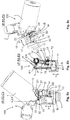
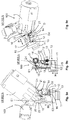
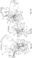
- the Figures 1a to 12c show a locking device 100 according to the invention for locking a functionally essential component of a motor vehicle, in particular a steering spindle.
- the functionally essential component is not shown in the figures for reasons of simplicity.
- the functionally essential component can represent any component of a steering system of the motor vehicle that has to be moved so that the motor vehicle can start off.
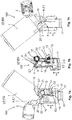
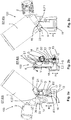
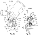
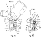
- the locking device 100 is designed with a first housing part 10, in which a locking pin 11 is movable between a locking position VP for locking the functionally essential component (see FIG Figures 1a to 1c , 3a and 3b ) and an unlocking position EP for releasing the functionally essential component (see the Figures 2a to 2c , 4a and 4b ) is included.
- the locking device 100 comprises a second housing part 20, in which means for moving the locking bolt 11 between the locking position and the unlocking position are accommodated.
- the view of Figures 1c and 2c a driver element 3 can be seen, which serves as a transmission element between the locking cylinder 1 and the locking pin 11 in order to move the locking pin 11 between the locking position VP and the unlocking position EP when the locking cylinder 1 rotates.
- the driver element 3 engages in an actuation guide 4 on the locking pin 11.
- a separable component 2 in the form of an electrical switch element which can be actuated in at least one key position in the locking cylinder 1, is arranged adjacent to the locking cylinder 1 on the second housing part 20.
- Figures 1a to 12c a securing element 12, for example in the form of a plate, which prevents movement of the locking pin 11 in an engagement position ES (see FIG Figures 8a to 8c and 12a to 12c ) and in a retracted position RS (see the Figures 1a to 4b and 5a to 5c and 9a to 9c) a movement of the locking pin 11 releases.
- the securing element 12 is acted upon by means of a securing spring 13 from the retracted position RS into the engagement position ES.
- the first housing part 10 has a mounting opening 17 in the form of a mounting slot in order to receive the securing element 12 essentially transversely to a stroke direction H of the locking bolt 11.
- This allows simple mounting of the spring element 14 on the first housing part 10. Due to the orientation of the mounting opening 17 essentially transverse to Stroke direction H of the locking pin 11 can ensure a quick and safe transfer of the securing element 12 from a retracted position RS into the engaged position ES.
- Figures 1a to 12c a spring element 14, which holds the securing element 12 in the retracted position RS with the aid of a spring-elastic preload V when the first housing part 10 is arranged on the second housing part 20 (see FIG Figures 1a to 4b as well as 5a to 5c and 9a to 9c), and in the engagement position ES by a springback R (see Figures 7a to 7c and 11a to 11c ), when the arrangement of the first housing part 10 is changed to the second housing part 20 (see Figures 6a to 6c and 10a to 10c ).
- the spring element 14 according to the invention is designed as a single, combined spring element 14 with a double function, which was previously implemented in the known locking devices by two separate spring elements.
- the spring element 14 according to the invention is supported on at least two components 11, 12 of the locking device 100, namely the locking pin 11 to act on the locking pin 11 from the unlocking position EP into the locking position VP, and the locking element 12 to the locking element 12 in the retracted position Hold RS when the first housing part 10 is arranged on the second housing part 20 (see Figures 1a to 5c and 9a to 9c ).
- a first lever arm section D1 and for supporting the spring element 14 on the securing element 12 are formed on the spring element 14 (see FIG Figures 1a to 12c ).
- a multifunctional spring element 14 is created by the two lever arm sections D1, D2.
- the spring element 14 can be referred to as a rotation spring, a leg spring or a torsion spring.
- a spring element 14 is a simple component that can be easily installed within the locking device 100.
- Such a rotary spring can store a resilient pretension V during an angular / rotary movement between the lever arm sections D1, D2 and release it again when relaxing.
- the spring element 14 has an end point E1 on the locking bolt side and an end point E2 on the securing element side, between the locking bolt end End point E1 and the securing element-side end point E2 is formed, preferably a two-sided and preferably angled lever.
- the spring element 14 can directly (see the Figures 1a to 2c and 5a to 8c ) or indirectly (see the Figures 3a to 4b and 9a to 12c ) be supported on the locking pin 11 and act on the locking pin 11 from the unlocking position EP into the locking position VP by means of a spring-elastic preload V.
- the spring element 14 is in the form of a two-part, in particular angular or leg spring-shaped, lever.
- the spring element 14 has the first lever arm section D1 on a load side and the second lever arm section D2 on a force side. Between the first lever arm section D1 and the second lever arm section D2, a spring-elastic pretension V is built up by pushing the lever arm sections D1, D2 apart.
- N of the locking device 100 as the Figures 1a to 4b and the Figures 5a to 5c and FIGS. 9a to 9c show, the spring element 14 is received pretensioned between the first housing part 10 and the second housing part 20.
- a support section D in the form of a coiled wire spring is provided as a stationary section of the spring element 14 to the two housing parts 10, 20 in normal operation N of the locking device 100, when the first housing part 10 is arranged on the second housing part 20.
- the support section D is Spring element 14 leaned against a holding section 21 on the second housing part 20, which adjoins a predetermined breaking point 22 between the first housing part 10 and the second housing part 20.
- the stationary support section D of the spring element 14 can be released, as a result of which the resilient prestress V in the spring element 14 can be reduced by a springback R, as will be explained below with the aid of the Figures 7a to 7c and 11a to 11c will be shown.
- a spring back R of the spring element 14 pushes the second lever arm section D2 out of a receiving bore 16 in the first housing part 10. This happens for the reason that the first lever arm section D1 releases by a rebound force due to the springback R of the spring element 14 to the released support section D, which is raised together with the second lever arm section D2.
- the second lever arm section D2 can thereby leave a holding opening 18 on the securing element 12 and thus release the securing element 12 for transfer in the unlocking direction S (see FIG Figures 8a to 8c and 12a to 12c).
- the securing spring 13 ensures that the securing element 12 is conveyed from the retracted position RS into the engaged position ES. It is conceivable that one and the same resilient bias voltage V serves both to act on the locking bolt 11 in normal operation N and to spring back the spring element 14 in a release direction S when attempting to break open.
- a further spring-elastic preload V for example by an interaction of the spring element 14 with the securing element 12, can be built up in the spring element 14 in order to support safe release of the securing element 12 when the locking device 100 is manipulated.
- the, preferably two-sided and preferably angular, lever between the locking pin-side end point E1 and the securing element-side end point E2 can have a load side essentially transversely to a stroke direction H of the locking pin 11 by a spring-elastic preload V. to transfer the locking pin 11.
- the lever can have a force side along an unlocking direction S, in order to enable springing back R of the spring element 14 to release the securing element 12 when the first housing part 10 and / or the second housing part 20 is manipulated.
- the first lever arm section D1 can be made shorter than the second lever arm section D2 of the spring element 14. With the same torque, a relatively high force can therefore be applied to the locking pin 11 on the shorter load side of the spring element 14, while on the force side of the spring element 14 a relatively low support force may be sufficient to maintain this force.
- the shorter first lever arm section D1 of the spring element 14 can also ensure an increased rebound force in the springback R of the spring element 14 when attempting to break open.
- the Figures 1a to 1c and 3a and 3b that the first lever arm section D1 of the spring element 14 can be aligned substantially transversely to a stroke direction H of the locking pin 11 when the locking pin 11 is in the locking position VP.
- the torque on the first lever arm section D1 thus acts in the locking position VP of the locking bolt essentially in the direction of the component to be locked.
- the spring element 14 can have a leg angle of approximately 90 ° in the preloaded state on the locking pin 11 in the locking position VP.
- Figures 2a to 2c and 4a and 4b show Figures 2a to 2c and 4a and 4b that the first lever arm section D1 of the spring element 14 can be oriented at an acute angle to the stroke direction H of the locking pin 11 when the locking pin 11 is in the unlocking position EP.
- the lever arm sections D1, D2 of the spring element 14 are pressed apart, as a result of which the spring preload V in the spring element 14 can be increased.
- the second lever arm section D2 of the spring element 14 can be aligned essentially along the stroke direction H of the locking pin 11.
- the second lever arm section D2 of the spring element 14 can be received in a receiving bore 16 in the first housing part 10, which extends essentially along the stroke direction H of the locking bolt 11.
- the second lever arm section D2 of the spring element 14 is essentially linearly displaceable in the event of a breakup, in order to ensure that the spring element 14 jumps out of engagement with the securing element 12.
- the locking device 100 can have a multi-stage locking groove T1 and possibly a further locking groove T2.
- the securing element 12 can be locked in the engagement position ES to lock the locking bolt 11 in order to prevent the locking bolt 11 from moving.
- the multi-stage locking groove T1 can serve to lock the locking bolt 11 in the locking position VP.
- the optional additional locking groove T2 can be used to lock the locking bolt 11 in the unlocking position EP. It is conceivable that the deepest step on this multi-step locking groove T1 is in the locking position VP of the locking bolt 11 with respect to the securing element 12.
- FIGS Figures 1a to 1c and 2a to 2c show a possible embodiment of a locking device 100 in the sense of the invention.
- the spring element 14 has an, in particular angled, contact section K, which on A stop section A of the locking pin 11 comes to rest resiliently when the first housing part 10 is arranged on the second housing part 20, as shown in FIGS Figures 1b , 2 B , 3b and 4b can be seen. Via the contact section K, the spring element 14 can act directly on the locking pin 11.
- the point where the contact section K is angled defines a constant leg length or a constant lever arm at the first lever arm section D1 of the spring element 14, with which the spring element 14 can act on the locking bolt 11.
- the length of the contact section 14 rests against the stop section A of the locking pin 11 and thus produces a stable support of the spring element 14 on the locking pin 11. A stable torque transmission between the spring element 14 and the locking pin 11 can thus be realized.
- the contact section K of the spring element 14 is slidably guided along the stop section A of the locking pin 11 when the locking pin 11 is moved between the locking position VP and the unlocking position EP. As a result, contact between the rotatable contact section K and the longitudinally displaceable locking bolt 11 can be maintained at a constant lever arm at the contact section K.
- first housing part 10 can be formed on the first housing part 10, for example an arcuate or circular, guide groove 15 in order to support the contact section K, in particular the locking pin-side end point E1, of the spring element 14 during the rotary movement, while the locking pin 11 between the locking position VP and the unlocking position EP is moved longitudinally.
- the movement of the first lever arm section D1 can be stabilized by the guide groove 15.
- the Figures 3a, 3b , 4a and 4b show a further possible embodiment of a locking device 100 in the sense of the invention.
- the spring element 14 has one straight first lever arm section D1, which resiliently rests on a pin 19 of the locking pin 11, which protrudes in a protruding manner, when the first housing part 10 is arranged on the second housing part 20.
- the spring element 14 can act indirectly on the locking pin 11 via the pin 19. With the pin 19 on the locking pin 11, a constant torque introduction point on the locking pin 11 can be provided, via which the spring element 14 can act in a stable, tilt-proof and reliable manner on the locking pin 11.
- the pin 19 thus serves as a transmission member between the spring element 14 and the locking pin 11.
- pin 19 more freedom of installation to flexibly meet the space requirements in the locking device 100. Furthermore, it is possible for the pin 19 on the locking pin 11 and the locking pin 11 itself to be provided as a monolithic and / or material-uniform component, for example an injection molded part. Furthermore, it is possible for the pin 19 to be subsequently mounted on the locking pin 11. It is even possible to upgrade conventional locking devices.
- the pin 19 is guided along the first lever arm section D1 of the spring element 14 when the locking pin 11 is moved between the locking position VP and the unlocking position EP.
- the spring element 14 acts with a variable lever on the locking pin 11.
- the locking pin 11 can be acted upon in the unlocking position EP with a greater force than in the locking position VP, in order to ensure that the locking pin 11 has the locking position VP after the motor vehicle has been switched off reached safely.
- FIGS. 9a to 12c explain a method according to the invention for securing a locking pin 11 of a locking device 100, which can be designed as described above.
- FIGS. 5a to 5c and 9a to 9c show the locking device 100 according to two exemplary embodiments described above in normal operation N.
- a change in the arrangement of the first housing part 10 relative to the second housing part 20 can be formed by manipulation, an attempt to break open and / or by separating the second housing part 20 from the first housing part 10. Since the separable component 2 is part of the second housing part 20, a change in the arrangement of the second housing part 20 relative to the first housing part 10 can also or particularly be caused by manipulation and / or by removing the separable component 2.
- a gap 23 is formed at a predetermined breaking point 22 between the first housing part 10 and the second housing part 20.
- a separable component 2 is arranged adjacent to the predetermined breaking point 22, so that the gap 23 can also be formed by manipulation and / or by removing the separable component 2.
- the predetermined breaking point 22 serves to allow a springback R of the spring element 14 to release the securing element 12 when the first housing part 10 and / or the second housing part 20 and / or the separable component 2 is manipulated.
- An unauthorized person can, for example, try to remove the second housing part 20 by means of an impact or a cutting tool in order to gain access to the locking pin 11 in the first housing part 10. When the first housing part 10 is opened, the locking pin 11 is exposed to unauthorized manipulations.
- the spring element 14 is released in order to reduce its resilient pretension V by a spring-back R, to release the securing element 12 and thus to lock the locking pin 11.
- the securing element 12 is located so far down in the first housing part 10 that even by opening the first housing part 10 the securing element 12 cannot be reached and the locking pin 11 cannot be manipulated. Theft of the motor vehicle by an unauthorized person can thus be effectively prevented.
- FIGS. 7a to 7c and 11a to 11c show a next method step in which the spring element 14 springs back: b) transfer of the spring element 14 along an unlocking direction S for unlocking the locking element 12.
- FIGS. 8a to 8c and 12a to 12c illustrate the next process step: c) transfer of the securing element 12 along an engagement direction E from the retracted position RS into the engagement position ES for locking the locking bolt 11.
- the locking device 100 described above and the method can provide reliable and secure tamper protection for the locking pin 11.
Landscapes
- Engineering & Computer Science (AREA)
- Mechanical Engineering (AREA)
- Lock And Its Accessories (AREA)
Claims (15)
- Dispositif de blocage (100) destiné à bloquer un composant fonctionnel essentiel d'un véhicule automobile, notamment un arbre de direction, avec
une première partie de boîtier (10) dans laquelle un goujon de blocage (11) est reçu de manière mobile entre une position de verrouillage (VP) pour verrouiller le composant fonctionnel essentiel et une position de déverrouillage (EP) pour libérer le composant fonctionnel essentiel,
une deuxième partie de boîtier (20) dans laquelle sont logés les moyens permettant de déplacer le goujon de blocage (11) entre la position de verrouillage (VP) et la position de déverrouillage (EP),
un élément de sécurité (12) qui, dans une position d'engagement (ES), empêche le mouvement du goujon de blocage (11) et, dans une position rétractée (RS), libère le mouvement du goujon de blocage (11),
et un élément de ressort (14) qui soutient l'élément de sécurité (12) en position rétractée (RS) au moyen d'une précontrainte élastique (V) lorsque la première partie du boîtier (10) est disposée sur la deuxième partie du boîtier (20),
et la libère en position d'engagement (ES) au moyen d'un ressort de rappel (R) lorsque la première partie du boîtier (10) est modifiée dans sa disposition par rapport à la deuxième partie du boîtier (20),
caractérise en ce
que l'élément de ressort (14) s'appuie sur le goujon de blocage (11) et agit sur le goujon de blocage (11) de la position déverrouillée (EP) à la position de verrouillage (VP) au moyen d'une précontrainte élastique (V). - Dispositif de blocage (100) selon la revendication 1,
caractérise en ce
que l'élément de ressort (14) est conçu sous la forme d'un ressort de rotation, en particulier un ressort de torsion,
dans lequel l'élément de ressort (14) est notamment formé d'un fil de ressort. - Dispositif de blocage (100) selon les revendications 1 ou 2,
caractérise en ce
que l'élément de ressort (14) présente une section de contact (K), notamment coudée, qui vient s'appuyer élastiquement sur une section de butée (A) du goujon de blocage (11) lorsque la première partie de boîtier (10) est disposée sur la deuxième partie de boîtier (20),
dans lequel, en particulier, une partie de contact (K) de l'élément de ressort (14) peut être guidée de manière déplaçable le long d'une partie de butée (A) du goujon de blocage (11) lorsque le goujon de blocage (11) est déplacé entre la position de verrouillage (VP) et la position de déverrouillage (EP). - Dispositif de blocage (100) selon l'une quelconque des revendications précédentes,
caractérise en ce
que l'élément de ressort (14) présente une première section de bras de levier (D1) qui vient s'appuyer élastiquement sur un axe (19), de préférence en saillie, du goujon de verrouillage (11) lorsque la première partie de boîtier (10) est disposée sur la deuxième partie de boîtier (20),
dans lequel en particulier une goupille (19) du boulon de verrouillage (11) peut être guidée de manière déplaçable le long d'une première partie de bras de levier (D1) de l'élément de ressort (14) lorsque le goujon de blocage (11) est déplacé entre la position de verrouillage (VP) et la position de déverrouillage (EP). - Dispositif de blocage (100) selon l'une quelconque des revendications précédentes,
caractérise en ce
qu'un point de rupture prédéterminé (22) est prévu entre la première partie de boîtier (10) et la deuxième partie de boîtier (20) afin de permettre un retour élastique (R) de l'élément de ressort (14) pour libérer l'élément de fixation (12) en cas de manipulation de la première partie de boîtier (10) et/ou de la deuxième partie de boîtier (20),
dans lequel, en particulier, un cylindre de fermeture (1) pour déplacer le goujon de blocage (11) dans la première partie de boîtier (10) est disposé sur la deuxième partie de boîtier (20), lequel cylindre peut être actionné avec une clé, de préférence par pression et/ou rotation. - Dispositif de blocage (100) selon l'une quelconque des revendications précédentes,
caractérise en ce
qu'une rainure de guidage (15) est formée sur la première partie du boîtier (10) afin de guider, de préférence de manière rotative, un point d'extrémité (E1) de l'élément de ressort (14) du côté du goujon de blocage lorsque le goujon de blocage (11) se déplace entre la position de verrouillage (VP) et la position de déverrouillage (EP),
et/ou en ce qu'une section de butée (A) du goujon de blocage (11), sur laquelle l'élément de ressort (14) vient s'appuyer de manière élastique, est orientée obliquement par rapport à une direction de course (H) du goujon de blocage (11). - Dispositif de blocage (100) selon l'une quelconque des revendications précédentes,
caractérise en ce
que le goujon de blocage (11) présente au moins une rainure de verrouillage (T1, T2), de préférence à plusieurs étages, dans laquelle l'élément de sécurité (12) peut être encliqueté dans la position d'engagement (ES) pour le verrouillage du goujon de blocage (11) afin d'empêcher le mouvement du goujon de blocage (11). - Dispositif de blocage (100) selon l'une quelconque des revendications précédentes,
caractérise en ce
que l'élément de ressort (14) présente un point d'extrémité (E1) du côté du goujon de blocage et un point d'extrémité (E2) du côté de l'élément de fixation,
dans lequel entre le point d'extrémité (E1) du côté du boulon de verrouillage et le point d'extrémité (E2) du côté de l'élément fusible, un levier, de préférence bilatéral et de préférence coudé, est formé,
dans lequel le levier présente en particulier un côté de charge sensiblement transversal à une direction de course (H) du goujon de blocage (11) afin de transmettre une précontrainte élastique (V) au goujon de blocage,
et/ou où le levier a un côté force le long d'une direction de déverrouillage (S) afin de permettre un retour élastique (R) de l'élément de ressort (14) pour libérer l'élément de fixation (12) lorsque la première partie du boîtier (10) et/ou la deuxième partie du boîtier (20) est manipulée. - Dispositif de blocage (100) selon l'une quelconque des revendications précédentes,
caractérise en ce
que l'élément de ressort (14) présente une première section de bras de levier (D1) pour l'appui d'une précontrainte élastique (V) sur le goujon de blocage (11) et une deuxième section de bras de levier (D2) pour le maintien de l'élément de fixation (12) dans la position rétractée (RS) lorsque la première partie de boîtier (10) est disposée sur la deuxième partie de boîtier (20),
dans lequel, en particulier, la première section du bras de levier (D1) est conçue plus courte que la deuxième section du bras de levier (D2). - Dispositif de blocage (100) selon l'une quelconque des revendications précédentes,
caractérise en ce
qu'une première partie de bras de levier (D1) de l'élément de ressort (14) est orientée sensiblement transversalement à une direction de course (H) du goujon de blocage (11) lorsque le goujon de blocage (11) se trouve dans la position de verrouillage (VP) et à un angle aigu par rapport à la direction de course (H) du boulon de verrouillage (11) lorsque le goujon de blocage (11) se trouve dans la position de déverrouillage (EP),
dans lequel en particulier une deuxième section de bras de levier (D2) de l'élément de ressort (14) est reçue dans un alésage de réception (16) dans la première partie de boîtier (10) sensiblement le long de la direction de la course (H) du boulon de verrouillage (11). - Dispositif de blocage (100) selon l'une quelconque des revendications précédentes,
caractérise en ce
que l'élément de ressort (14) est reçu de manière précontrainte entre la première partie de boîtier (10) et la deuxième partie de boîtier (20) lorsque la première partie de boîtier (10) est disposée sur la deuxième partie de boîtier (20),
dans lequel en particulier l'élément de ressort (14), de préférence une deuxième section de bras de levier (D2) de l'élément de ressort (14), est déplaçable de manière sensiblement linéaire lorsque la première partie de boîtier (10) est modifiée dans sa disposition par rapport à la deuxième partie de boîtier (20). - Dispositif de blocage (100) selon l'une quelconque des revendications précédentes,
caractérise en ce
que l'élément de ressort (14), en particulier entre une première section de bras de levier (D1) et une deuxième section de bras de levier (D2), présente au moins une section d'appui (D) qui vient s'appuyer sur la première partie de boîtier (10) et/ou sur la deuxième partie de boîtier (20) lorsque la première partie de boîtier (10) est disposée sur la deuxième partie de boîtier (20), la section d'appui (D) étant libérée lorsque la première partie de boîtier (10) est modifiée dans sa disposition par rapport à la deuxième partie de boîtier (20). - Dispositif de blocage (100) selon l'une quelconque des revendications précédentes,
caractérise en ce
que la première partie du boîtier (10) présente une ouverture de montage (17), de préférence sous la forme d'une fente de montage, pour l'élément de fixation (12) afin de recevoir l'élément de fixation (12) essentiellement transversalement par rapport à une direction de levage (H) du boulon de verrouillage (11),
dans lequel il est prévu en particulier un ressort de sécurité (13) qui agit sur l'élément de sécurité (12) de la position rétractée (RS) à la position engagée (ES) sensiblement transversalement à une direction de course (H),
et/ou dans lequel, de préférence, l'élément de fixation (12) est conçu sous la forme d'une petite plaque, de préférence en acier à ressort. - Dispositif de blocage (100) selon l'une quelconque des revendications précédentes,
caractérise en ce
qu'un composant séparable (2) est disposé sur la deuxième partie de boîtier (20), le composant séparable (2) étant de préférence contigu à un point de rupture (22) entre la première partie de boîtier (10) et la deuxième partie de boîtier (20), et/ou en particulier le composant séparable (2) étant un élément de commutation électrique. - Méthode pour sécuriser un goujon de blocage (11) d'un dispositif de blocage (100) selon l'une quelconque des revendications précédentes, réalisé avec
une première partie de boîtier (10) dans laquelle un goujon de blocage (11) est reçu de manière mobile entre une position de verrouillage (VP) pour verrouiller le composant fonctionnel essentiel et une position de déverrouillage (EP) pour libérer le composant fonctionnel essentiel,
une deuxième partie de boîtier (20) dans laquelle sont logés les moyens permettant de déplacer le goujon de blocage (11) entre la position de verrouillage (VP) et la position de déverrouillage (EP),
un élément de sécurité (12) qui, dans une position d'engagement (ES), empêche le mouvement du goujon de blocage (11) et, dans une position rétractée (RS), libère le mouvement du goujon de blocage (11),
et un élément de ressort (14), qui s'appuie sur le goujon de blocage (11) et qui agit sur le goujon de blocage (11) de la position déverrouillée (EP) à la position de verrouillage (VP) au moyen d'une précontrainte élastique (V),
caractérise en ce
que la méthode comprend les étapes suivantes :a) la modification de la disposition de la première partie de boîtier (10) par rapport à la deuxième partie de boîtier (20),b) le transfert de l'élément de ressort (14) dans une direction de déverrouillage (S) pour déverrouiller l'élément de sécurité (12),c) le transfert de l'élément de sécurité (12) le long d'une direction d'engagement (E) de la position rétractée (RS) à la position d'engagement (ES) pour le verrouillage du goujon de blocage (11).
Applications Claiming Priority (1)
| Application Number | Priority Date | Filing Date | Title |
|---|---|---|---|
| DE102017116898.2A DE102017116898A1 (de) | 2017-07-26 | 2017-07-26 | Sperrvorrichtung zum Sperren eines funktionswesentlichen Bauteils eines Kraftfahrzeugs und Verfahren zum Sichern eines Sperrbolzens einer Sperrvorrichtung |
Publications (2)
| Publication Number | Publication Date |
|---|---|
| EP3434534A1 EP3434534A1 (fr) | 2019-01-30 |
| EP3434534B1 true EP3434534B1 (fr) | 2020-07-15 |
Family
ID=63014383
Family Applications (1)
| Application Number | Title | Priority Date | Filing Date |
|---|---|---|---|
| EP18184684.1A Active EP3434534B1 (fr) | 2017-07-26 | 2018-07-20 | Dispositif de blocage destiné à bloquer un composant essentiel au fonctionnement d'un véhicule automobile et procédé de fixation d'une goupille de blocage d'un dispositif de blocage |
Country Status (2)
| Country | Link |
|---|---|
| EP (1) | EP3434534B1 (fr) |
| DE (1) | DE102017116898A1 (fr) |
Family Cites Families (8)
| Publication number | Priority date | Publication date | Assignee | Title |
|---|---|---|---|---|
| DE29806390U1 (de) * | 1998-04-07 | 1998-08-20 | Huf Hülsbeck & Fürst GmbH & Co. KG, 42551 Velbert | Lenkschloß für Kraftfahrzeuge |
| FR2810284B1 (fr) * | 2000-06-20 | 2002-09-06 | Valeo Securite Habitacle | Antivol de colonne de direction muni de moyens de blocage du pene |
| JP2007177578A (ja) * | 2005-12-28 | 2007-07-12 | Tokai Rika Co Ltd | ステアリングロック装置 |
| DE102007059712A1 (de) * | 2007-12-10 | 2009-06-25 | Huf Hülsbeck & Fürst Gmbh & Co. Kg | Vorrichtung zur Ansteuerung eines Sperrgliedes |
| DE102009034606B4 (de) * | 2009-07-24 | 2019-08-29 | Huf Hülsbeck & Fürst Gmbh & Co. Kg | Vorrichtung zum Sperren eines funktionswesentlichen Bauteils eines Kraftfahrzeugs |
| DE102010037071A1 (de) * | 2010-08-19 | 2012-02-23 | Huf Hülsbeck & Fürst Gmbh & Co. Kg | Vorrichtung zur Verlagerung eines bewegbaren Sperrelementes |
| JP5965202B2 (ja) * | 2012-04-27 | 2016-08-03 | 株式会社アルファ | ステアリングロック装置 |
| DE102014112816A1 (de) * | 2014-09-05 | 2016-03-10 | Huf Hülsbeck & Fürst Gmbh & Co. Kg | Lenkradverriegelung |
-
2017
- 2017-07-26 DE DE102017116898.2A patent/DE102017116898A1/de not_active Withdrawn
-
2018
- 2018-07-20 EP EP18184684.1A patent/EP3434534B1/fr active Active
Non-Patent Citations (1)
| Title |
|---|
| None * |
Also Published As
| Publication number | Publication date |
|---|---|
| DE102017116898A1 (de) | 2019-01-31 |
| EP3434534A1 (fr) | 2019-01-30 |
Similar Documents
| Publication | Publication Date | Title |
|---|---|---|
| EP3126600B1 (fr) | Dispositif d'actionnement pour serrure de véhicule à moteur | |
| DE69922373T2 (de) | Verschlussvorrichtung und haubenschloss für ein fahrzeug mit einer derartigen verschlussvorrichtung | |
| EP3153648B1 (fr) | Cadenas | |
| WO2018137817A1 (fr) | Système de poignée de porte pour une porte de véhicule | |
| EP3999406B1 (fr) | Système de serrure | |
| EP3066282B1 (fr) | Moyen de fermeture d'une porte ou d'un ouvrant | |
| DE9208698U1 (de) | Lenkradschloß | |
| EP3060735B1 (fr) | Serrure de portière de véhicule automobile | |
| EP2420416A2 (fr) | Dispositif de logement d'un élément de blocage mobile | |
| EP3117056B1 (fr) | Cylindre de fermeture pour dispositif à serrure | |
| EP2993090B1 (fr) | Verrouillage de volant de direction | |
| EP3296164B1 (fr) | Dispositif sécurisé de fermeture d'un composant essentiellement fonctionnel du véhicule automobile | |
| EP1764293B1 (fr) | Serrure pour frein à disque | |
| EP3434534B1 (fr) | Dispositif de blocage destiné à bloquer un composant essentiel au fonctionnement d'un véhicule automobile et procédé de fixation d'une goupille de blocage d'un dispositif de blocage | |
| EP3117057B1 (fr) | Système de fermeture de portière de véhicule automobile | |
| EP1069010B1 (fr) | Verrou de direction de véhicule automobile | |
| EP0831198A1 (fr) | Cadenas | |
| DE4339654C3 (de) | Kraftfahrzeugtürverschluß | |
| DE19921889A1 (de) | Zündschloß für ein Kraftfahrzeug | |
| EP1387783B1 (fr) | Demarreur a commande manuelle pour unite sans cle servant au controle d'autorisation de demarrage de moteur d'un vehicule automobile | |
| EP3002162A1 (fr) | Dispositif de verrouillage securise | |
| EP3453579B1 (fr) | Dispositif de verrouillage | |
| EP3372458B1 (fr) | Dispositif de fermeture | |
| DE102016004835B4 (de) | Sicherheitsschalter | |
| DE2322330C3 (de) | Kraftfahrzeug-Lenkschloß |
Legal Events
| Date | Code | Title | Description |
|---|---|---|---|
| PUAI | Public reference made under article 153(3) epc to a published international application that has entered the european phase |
Free format text: ORIGINAL CODE: 0009012 |
|
| STAA | Information on the status of an ep patent application or granted ep patent |
Free format text: STATUS: THE APPLICATION HAS BEEN PUBLISHED |
|
| AK | Designated contracting states |
Kind code of ref document: A1 Designated state(s): AL AT BE BG CH CY CZ DE DK EE ES FI FR GB GR HR HU IE IS IT LI LT LU LV MC MK MT NL NO PL PT RO RS SE SI SK SM TR |
|
| AX | Request for extension of the european patent |
Extension state: BA ME |
|
| STAA | Information on the status of an ep patent application or granted ep patent |
Free format text: STATUS: REQUEST FOR EXAMINATION WAS MADE |
|
| 17P | Request for examination filed |
Effective date: 20190730 |
|
| RBV | Designated contracting states (corrected) |
Designated state(s): AL AT BE BG CH CY CZ DE DK EE ES FI FR GB GR HR HU IE IS IT LI LT LU LV MC MK MT NL NO PL PT RO RS SE SI SK SM TR |
|
| GRAP | Despatch of communication of intention to grant a patent |
Free format text: ORIGINAL CODE: EPIDOSNIGR1 |
|
| STAA | Information on the status of an ep patent application or granted ep patent |
Free format text: STATUS: GRANT OF PATENT IS INTENDED |
|
| INTG | Intention to grant announced |
Effective date: 20200122 |
|
| GRAS | Grant fee paid |
Free format text: ORIGINAL CODE: EPIDOSNIGR3 |
|
| GRAA | (expected) grant |
Free format text: ORIGINAL CODE: 0009210 |
|
| STAA | Information on the status of an ep patent application or granted ep patent |
Free format text: STATUS: THE PATENT HAS BEEN GRANTED |
|
| AK | Designated contracting states |
Kind code of ref document: B1 Designated state(s): AL AT BE BG CH CY CZ DE DK EE ES FI FR GB GR HR HU IE IS IT LI LT LU LV MC MK MT NL NO PL PT RO RS SE SI SK SM TR |
|
| REG | Reference to a national code |
Ref country code: CH Ref legal event code: EP Ref country code: GB Ref legal event code: FG4D Free format text: NOT ENGLISH |
|
| REG | Reference to a national code |
Ref country code: IE Ref legal event code: FG4D Free format text: LANGUAGE OF EP DOCUMENT: GERMAN |
|
| REG | Reference to a national code |
Ref country code: DE Ref legal event code: R096 Ref document number: 502018001889 Country of ref document: DE |
|
| REG | Reference to a national code |
Ref country code: AT Ref legal event code: REF Ref document number: 1290689 Country of ref document: AT Kind code of ref document: T Effective date: 20200815 |
|
| REG | Reference to a national code |
Ref country code: LT Ref legal event code: MG4D |
|
| REG | Reference to a national code |
Ref country code: NL Ref legal event code: MP Effective date: 20200715 |
|
| PG25 | Lapsed in a contracting state [announced via postgrant information from national office to epo] |
Ref country code: FI Free format text: LAPSE BECAUSE OF FAILURE TO SUBMIT A TRANSLATION OF THE DESCRIPTION OR TO PAY THE FEE WITHIN THE PRESCRIBED TIME-LIMIT Effective date: 20200715 Ref country code: LT Free format text: LAPSE BECAUSE OF FAILURE TO SUBMIT A TRANSLATION OF THE DESCRIPTION OR TO PAY THE FEE WITHIN THE PRESCRIBED TIME-LIMIT Effective date: 20200715 Ref country code: BG Free format text: LAPSE BECAUSE OF FAILURE TO SUBMIT A TRANSLATION OF THE DESCRIPTION OR TO PAY THE FEE WITHIN THE PRESCRIBED TIME-LIMIT Effective date: 20201015 Ref country code: PT Free format text: LAPSE BECAUSE OF FAILURE TO SUBMIT A TRANSLATION OF THE DESCRIPTION OR TO PAY THE FEE WITHIN THE PRESCRIBED TIME-LIMIT Effective date: 20201116 Ref country code: ES Free format text: LAPSE BECAUSE OF FAILURE TO SUBMIT A TRANSLATION OF THE DESCRIPTION OR TO PAY THE FEE WITHIN THE PRESCRIBED TIME-LIMIT Effective date: 20200715 Ref country code: NO Free format text: LAPSE BECAUSE OF FAILURE TO SUBMIT A TRANSLATION OF THE DESCRIPTION OR TO PAY THE FEE WITHIN THE PRESCRIBED TIME-LIMIT Effective date: 20201015 Ref country code: GR Free format text: LAPSE BECAUSE OF FAILURE TO SUBMIT A TRANSLATION OF THE DESCRIPTION OR TO PAY THE FEE WITHIN THE PRESCRIBED TIME-LIMIT Effective date: 20201016 Ref country code: SE Free format text: LAPSE BECAUSE OF FAILURE TO SUBMIT A TRANSLATION OF THE DESCRIPTION OR TO PAY THE FEE WITHIN THE PRESCRIBED TIME-LIMIT Effective date: 20200715 Ref country code: HR Free format text: LAPSE BECAUSE OF FAILURE TO SUBMIT A TRANSLATION OF THE DESCRIPTION OR TO PAY THE FEE WITHIN THE PRESCRIBED TIME-LIMIT Effective date: 20200715 |
|
| PG25 | Lapsed in a contracting state [announced via postgrant information from national office to epo] |
Ref country code: PL Free format text: LAPSE BECAUSE OF FAILURE TO SUBMIT A TRANSLATION OF THE DESCRIPTION OR TO PAY THE FEE WITHIN THE PRESCRIBED TIME-LIMIT Effective date: 20200715 Ref country code: RS Free format text: LAPSE BECAUSE OF FAILURE TO SUBMIT A TRANSLATION OF THE DESCRIPTION OR TO PAY THE FEE WITHIN THE PRESCRIBED TIME-LIMIT Effective date: 20200715 Ref country code: LV Free format text: LAPSE BECAUSE OF FAILURE TO SUBMIT A TRANSLATION OF THE DESCRIPTION OR TO PAY THE FEE WITHIN THE PRESCRIBED TIME-LIMIT Effective date: 20200715 Ref country code: IS Free format text: LAPSE BECAUSE OF FAILURE TO SUBMIT A TRANSLATION OF THE DESCRIPTION OR TO PAY THE FEE WITHIN THE PRESCRIBED TIME-LIMIT Effective date: 20201115 |
|
| PG25 | Lapsed in a contracting state [announced via postgrant information from national office to epo] |
Ref country code: NL Free format text: LAPSE BECAUSE OF FAILURE TO SUBMIT A TRANSLATION OF THE DESCRIPTION OR TO PAY THE FEE WITHIN THE PRESCRIBED TIME-LIMIT Effective date: 20200715 |
|
| REG | Reference to a national code |
Ref country code: DE Ref legal event code: R097 Ref document number: 502018001889 Country of ref document: DE |
|
| REG | Reference to a national code |
Ref country code: BE Ref legal event code: MM Effective date: 20200731 |
|
| PG25 | Lapsed in a contracting state [announced via postgrant information from national office to epo] |
Ref country code: RO Free format text: LAPSE BECAUSE OF FAILURE TO SUBMIT A TRANSLATION OF THE DESCRIPTION OR TO PAY THE FEE WITHIN THE PRESCRIBED TIME-LIMIT Effective date: 20200715 Ref country code: DK Free format text: LAPSE BECAUSE OF FAILURE TO SUBMIT A TRANSLATION OF THE DESCRIPTION OR TO PAY THE FEE WITHIN THE PRESCRIBED TIME-LIMIT Effective date: 20200715 Ref country code: CZ Free format text: LAPSE BECAUSE OF FAILURE TO SUBMIT A TRANSLATION OF THE DESCRIPTION OR TO PAY THE FEE WITHIN THE PRESCRIBED TIME-LIMIT Effective date: 20200715 Ref country code: EE Free format text: LAPSE BECAUSE OF FAILURE TO SUBMIT A TRANSLATION OF THE DESCRIPTION OR TO PAY THE FEE WITHIN THE PRESCRIBED TIME-LIMIT Effective date: 20200715 Ref country code: IT Free format text: LAPSE BECAUSE OF FAILURE TO SUBMIT A TRANSLATION OF THE DESCRIPTION OR TO PAY THE FEE WITHIN THE PRESCRIBED TIME-LIMIT Effective date: 20200715 Ref country code: LU Free format text: LAPSE BECAUSE OF NON-PAYMENT OF DUE FEES Effective date: 20200720 Ref country code: SM Free format text: LAPSE BECAUSE OF FAILURE TO SUBMIT A TRANSLATION OF THE DESCRIPTION OR TO PAY THE FEE WITHIN THE PRESCRIBED TIME-LIMIT Effective date: 20200715 |
|
| PLBE | No opposition filed within time limit |
Free format text: ORIGINAL CODE: 0009261 |
|
| STAA | Information on the status of an ep patent application or granted ep patent |
Free format text: STATUS: NO OPPOSITION FILED WITHIN TIME LIMIT |
|
| PG25 | Lapsed in a contracting state [announced via postgrant information from national office to epo] |
Ref country code: AL Free format text: LAPSE BECAUSE OF FAILURE TO SUBMIT A TRANSLATION OF THE DESCRIPTION OR TO PAY THE FEE WITHIN THE PRESCRIBED TIME-LIMIT Effective date: 20200715 Ref country code: BE Free format text: LAPSE BECAUSE OF NON-PAYMENT OF DUE FEES Effective date: 20200731 |
|
| 26N | No opposition filed |
Effective date: 20210416 |
|
| PG25 | Lapsed in a contracting state [announced via postgrant information from national office to epo] |
Ref country code: SK Free format text: LAPSE BECAUSE OF FAILURE TO SUBMIT A TRANSLATION OF THE DESCRIPTION OR TO PAY THE FEE WITHIN THE PRESCRIBED TIME-LIMIT Effective date: 20200715 |
|
| PG25 | Lapsed in a contracting state [announced via postgrant information from national office to epo] |
Ref country code: FR Free format text: LAPSE BECAUSE OF NON-PAYMENT OF DUE FEES Effective date: 20200915 |
|
| PG25 | Lapsed in a contracting state [announced via postgrant information from national office to epo] |
Ref country code: IE Free format text: LAPSE BECAUSE OF NON-PAYMENT OF DUE FEES Effective date: 20200720 Ref country code: SI Free format text: LAPSE BECAUSE OF FAILURE TO SUBMIT A TRANSLATION OF THE DESCRIPTION OR TO PAY THE FEE WITHIN THE PRESCRIBED TIME-LIMIT Effective date: 20200715 |
|
| PGFP | Annual fee paid to national office [announced via postgrant information from national office to epo] |
Ref country code: DE Payment date: 20210731 Year of fee payment: 4 |
|
| REG | Reference to a national code |
Ref country code: CH Ref legal event code: PL |
|
| PG25 | Lapsed in a contracting state [announced via postgrant information from national office to epo] |
Ref country code: LI Free format text: LAPSE BECAUSE OF NON-PAYMENT OF DUE FEES Effective date: 20210731 Ref country code: CH Free format text: LAPSE BECAUSE OF NON-PAYMENT OF DUE FEES Effective date: 20210731 |
|
| PG25 | Lapsed in a contracting state [announced via postgrant information from national office to epo] |
Ref country code: TR Free format text: LAPSE BECAUSE OF FAILURE TO SUBMIT A TRANSLATION OF THE DESCRIPTION OR TO PAY THE FEE WITHIN THE PRESCRIBED TIME-LIMIT Effective date: 20200715 Ref country code: MT Free format text: LAPSE BECAUSE OF FAILURE TO SUBMIT A TRANSLATION OF THE DESCRIPTION OR TO PAY THE FEE WITHIN THE PRESCRIBED TIME-LIMIT Effective date: 20200715 Ref country code: CY Free format text: LAPSE BECAUSE OF FAILURE TO SUBMIT A TRANSLATION OF THE DESCRIPTION OR TO PAY THE FEE WITHIN THE PRESCRIBED TIME-LIMIT Effective date: 20200715 |
|
| PG25 | Lapsed in a contracting state [announced via postgrant information from national office to epo] |
Ref country code: MK Free format text: LAPSE BECAUSE OF FAILURE TO SUBMIT A TRANSLATION OF THE DESCRIPTION OR TO PAY THE FEE WITHIN THE PRESCRIBED TIME-LIMIT Effective date: 20200715 Ref country code: MC Free format text: LAPSE BECAUSE OF FAILURE TO SUBMIT A TRANSLATION OF THE DESCRIPTION OR TO PAY THE FEE WITHIN THE PRESCRIBED TIME-LIMIT Effective date: 20200715 |
|
| REG | Reference to a national code |
Ref country code: DE Ref legal event code: R119 Ref document number: 502018001889 Country of ref document: DE |
|
| GBPC | Gb: european patent ceased through non-payment of renewal fee |
Effective date: 20220720 |
|
| PG25 | Lapsed in a contracting state [announced via postgrant information from national office to epo] |
Ref country code: GB Free format text: LAPSE BECAUSE OF NON-PAYMENT OF DUE FEES Effective date: 20220720 Ref country code: DE Free format text: LAPSE BECAUSE OF NON-PAYMENT OF DUE FEES Effective date: 20230201 |
|
| P01 | Opt-out of the competence of the unified patent court (upc) registered |
Effective date: 20230427 |
|
| REG | Reference to a national code |
Ref country code: AT Ref legal event code: MM01 Ref document number: 1290689 Country of ref document: AT Kind code of ref document: T Effective date: 20230720 |
|
| PG25 | Lapsed in a contracting state [announced via postgrant information from national office to epo] |
Ref country code: AT Free format text: LAPSE BECAUSE OF NON-PAYMENT OF DUE FEES Effective date: 20230720 |
|
| PG25 | Lapsed in a contracting state [announced via postgrant information from national office to epo] |
Ref country code: AT Free format text: LAPSE BECAUSE OF NON-PAYMENT OF DUE FEES Effective date: 20230720 |
|
| PGFP | Annual fee paid to national office [announced via postgrant information from national office to epo] |
Ref country code: AT Payment date: 20260410 Year of fee payment: 5 |