EP3434632B1 - Dispositif et procédé d'acheminement de matériau constitué d'au moins principalement de particules solides, en particulier poudre, par exemple mortier sec - Google Patents
Dispositif et procédé d'acheminement de matériau constitué d'au moins principalement de particules solides, en particulier poudre, par exemple mortier sec Download PDFInfo
- Publication number
- EP3434632B1 EP3434632B1 EP17183046.6A EP17183046A EP3434632B1 EP 3434632 B1 EP3434632 B1 EP 3434632B1 EP 17183046 A EP17183046 A EP 17183046A EP 3434632 B1 EP3434632 B1 EP 3434632B1
- Authority
- EP
- European Patent Office
- Prior art keywords
- conveying
- vessel
- outlet
- conveyor
- screw conveyor
- Prior art date
- Legal status (The legal status is an assumption and is not a legal conclusion. Google has not performed a legal analysis and makes no representation as to the accuracy of the status listed.)
- Active
Links
Images

Classifications
-
- B—PERFORMING OPERATIONS; TRANSPORTING
- B65—CONVEYING; PACKING; STORING; HANDLING THIN OR FILAMENTARY MATERIAL
- B65G—TRANSPORT OR STORAGE DEVICES, e.g. CONVEYORS FOR LOADING OR TIPPING, SHOP CONVEYOR SYSTEMS OR PNEUMATIC TUBE CONVEYORS
- B65G53/00—Conveying materials in bulk through troughs, pipes or tubes by floating the materials or by flow of gas, liquid or foam
- B65G53/34—Details
- B65G53/52—Adaptations of pipes or tubes
-
- B—PERFORMING OPERATIONS; TRANSPORTING
- B65—CONVEYING; PACKING; STORING; HANDLING THIN OR FILAMENTARY MATERIAL
- B65G—TRANSPORT OR STORAGE DEVICES, e.g. CONVEYORS FOR LOADING OR TIPPING, SHOP CONVEYOR SYSTEMS OR PNEUMATIC TUBE CONVEYORS
- B65G53/00—Conveying materials in bulk through troughs, pipes or tubes by floating the materials or by flow of gas, liquid or foam
- B65G53/04—Conveying materials in bulk pneumatically through pipes or tubes; Air slides
- B65G53/06—Gas pressure systems operating without fluidisation of the materials
- B65G53/08—Gas pressure systems operating without fluidisation of the materials with mechanical injection of the materials, e.g. by screw
-
- B—PERFORMING OPERATIONS; TRANSPORTING
- B65—CONVEYING; PACKING; STORING; HANDLING THIN OR FILAMENTARY MATERIAL
- B65G—TRANSPORT OR STORAGE DEVICES, e.g. CONVEYORS FOR LOADING OR TIPPING, SHOP CONVEYOR SYSTEMS OR PNEUMATIC TUBE CONVEYORS
- B65G53/00—Conveying materials in bulk through troughs, pipes or tubes by floating the materials or by flow of gas, liquid or foam
- B65G53/34—Details
-
- B—PERFORMING OPERATIONS; TRANSPORTING
- B65—CONVEYING; PACKING; STORING; HANDLING THIN OR FILAMENTARY MATERIAL
- B65G—TRANSPORT OR STORAGE DEVICES, e.g. CONVEYORS FOR LOADING OR TIPPING, SHOP CONVEYOR SYSTEMS OR PNEUMATIC TUBE CONVEYORS
- B65G53/00—Conveying materials in bulk through troughs, pipes or tubes by floating the materials or by flow of gas, liquid or foam
- B65G53/34—Details
- B65G53/36—Arrangements of containers
-
- B—PERFORMING OPERATIONS; TRANSPORTING
- B65—CONVEYING; PACKING; STORING; HANDLING THIN OR FILAMENTARY MATERIAL
- B65G—TRANSPORT OR STORAGE DEVICES, e.g. CONVEYORS FOR LOADING OR TIPPING, SHOP CONVEYOR SYSTEMS OR PNEUMATIC TUBE CONVEYORS
- B65G53/00—Conveying materials in bulk through troughs, pipes or tubes by floating the materials or by flow of gas, liquid or foam
- B65G53/34—Details
- B65G53/40—Feeding or discharging devices
- B65G53/48—Screws or like rotary conveyors
-
- B—PERFORMING OPERATIONS; TRANSPORTING
- B65—CONVEYING; PACKING; STORING; HANDLING THIN OR FILAMENTARY MATERIAL
- B65G—TRANSPORT OR STORAGE DEVICES, e.g. CONVEYORS FOR LOADING OR TIPPING, SHOP CONVEYOR SYSTEMS OR PNEUMATIC TUBE CONVEYORS
- B65G2203/00—Indexing code relating to control or detection of the articles or the load carriers during conveying
- B65G2203/04—Detection means
- B65G2203/042—Sensors
-
- B—PERFORMING OPERATIONS; TRANSPORTING
- B65—CONVEYING; PACKING; STORING; HANDLING THIN OR FILAMENTARY MATERIAL
- B65G—TRANSPORT OR STORAGE DEVICES, e.g. CONVEYORS FOR LOADING OR TIPPING, SHOP CONVEYOR SYSTEMS OR PNEUMATIC TUBE CONVEYORS
- B65G53/00—Conveying materials in bulk through troughs, pipes or tubes by floating the materials or by flow of gas, liquid or foam
- B65G53/34—Details
- B65G53/66—Use of indicator or control devices, e.g. for controlling gas pressure, for controlling proportions of material and gas, for indicating or preventing jamming of material
Definitions
- the invention relates to a device for conveying material consisting at least predominantly of solid particles, in particular powder material, for example dry mortar, with a conveyor vessel which can be coupled or is coupled with an inlet opening to an outlet opening of a storage container, for example a silo.
- the conveyor vessel has a conveyor vessel outlet to which a conveyor line, in particular a hose line, can be connected or is connected.
- the conveyor vessel can also be supplied with conveying air for transporting the material to be conveyed in the direction of the conveyor vessel outlet.
- a screw conveyor is arranged at least partially within the conveyor vessel for transporting and dosing material, the transport path of which leads to an outlet-side interior region of the conveyor vessel.
- the invention further relates to a method for conveying such material consisting at least predominantly of solid particles, in particular using such a device.
- materials consisting predominantly of solid particles, in particular powder, dust or granular materials, such as cement, gypsum, dry mortar, screed or mixtures thereof, are delivered in a dry state to the place of use, e.g. to a construction site, and stored there in a storage container, in particular a silo. There, these materials are removed from this silo when required and transported by means of a conveyor device a processing device, such as a plastering machine or the like. In this processing device, the dry material is mixed with water and subjected to further processing.
- a processing device such as a plastering machine or the like.
- a conveyor device To transport the material from the silo to the processing facility, a conveyor device is usually used that is designed to convey the material to be transported with the aid of compressed air.
- This conveyor device is known to have a conveyor vessel with an inlet opening that is connected to an outlet opening of the silo so that the material stored in the silo can be fed to the conveyor vessel.
- the conveyor vessel also comprises an outlet to which a conveyor line is usually attached for coupling to the processing facility.
- Such a conveyor device is known from the German utility model DE 20 2008 013 042 U1 known.
- an interior air inlet for introducing conveying air is arranged in such a way that the introduced conveying air is directed to a conveyor vessel outlet for conveying the material.
- the present invention has for its object to provide a device for conveying material consisting at least predominantly of solid particles according to the preamble of patent claim 1, which ensures a homogeneous material flow, in particular even when materials to be conveyed have an increased dry weight.
- an interior air inlet for introducing conveying air into the outlet-side interior area is arranged or aligned in such a way that the introduced conveying air is essentially directed towards the conveyor vessel outlet, wherein the transport of the material up to the outlet-side interior area of the conveyor vessel takes place by the screw conveyor, while the transport of the material from the outlet-side interior area of the conveyor vessel takes place by the conveying air.
- the screw conveyor ensures that a constant flow of material can be supplied to the outlet-side interior area, at least as long as the conveyor vessel still contains material to be conveyed.
- the conveying capacity of the screw conveyor is largely constant, at least for the materials in question here.
- the material flow can therefore be dosed in such a targeted manner that the conveyed material can be transported further through the conveyor line starting from the outlet-side interior area with the help of the conveying air introduced and utilising the Venturi effect.
- the screw conveyor is also suitable for mechanically breaking up existing material compactions and thus also serves to loosen the conveyed material. This is particularly advantageous for applications in which the material to be conveyed has a higher specific weight or density. has an increased density or tends to form lumps or plugs for other reasons.
- the proposed device is designed to provide a steady and homogeneous material flow, in particular for a processing device that processes the material.
- the material which consists at least predominantly of solid particles, in particular powder material, is, for example, a dry mortar or dry plaster, cement, screed or mortar.
- the processing device connected or connectable to the device via the conveyor line is, for example, a plastering machine.
- a uniform conveyor flow ensures efficient and clean processing of the conveyed material.
- the screw conveyor preferably comprises at least one helical conveyor screw for transporting the material in the axial direction, which conveyor screw is rotatable about an axis of rotation and is arranged essentially horizontally, in particular with respect to the gravitational field.
- the conveyor screw is arranged in particular in a lower region of the conveyor vessel and runs, for example, in a horizontal direction in a channel-shaped depression of a housing of the conveyor vessel.
- the conveyor screw which is rotatable about the axis of rotation, essentially defines the transport path of the screw conveyor.
- at least one region of the conveyor screw is freely accessible from above. If the conveyor vessel is filled with material, this falls downwards under the influence of gravity into an area in which it can be transported by means of the screw conveyor in an essentially horizontal direction to the conveyor vessel outlet.
- the conveyor screw is surrounded by a pipe section, in particular a cylindrical one, at least in the outlet-side inner area.
- a pipe section in particular a cylindrical one, at least in the outlet-side inner area.
- a drive of the screw conveyor is designed to convey material with a specific weight of more than 1.3 kg/dm 3 , based on the dry weight.
- the drive of the screw conveyor is designed in particular to convey materials that tend to form compactions due to their relatively high specific weight.
- a conveying line with a lockable valve is preferably connected to the conveyor vessel outlet.
- a bypass air inlet for introducing conveying air is further preferably arranged downstream of the valve in such a way that the conveying air introduced is directed essentially away from the conveyor vessel outlet, so that by blowing in conveying air an air flow can be generated in the direction of the connected or connectable conveying line.
- Conveying air can be blown into the connected or connectable conveying line via the bypass air inlet, in particular even when the valve is closed.
- the device for conveying material consisting at least predominantly of solid particles, in particular powder material, for example dry mortar, comprises a conveying vessel which can be coupled or is coupled with an inlet opening to an outlet opening of a storage container, for example a silo.
- the conveying vessel has a conveying vessel outlet to which a conveying line, in particular a hose line, can be connected or is connected.
- the material can be conveyed to an outlet-side inner area in one possible embodiment exclusively by the influence of gravity, in particular via correspondingly inclined wall sections or sheets.
- the screw conveyor already mentioned above is provided for conveying the material within the conveying vessel.
- the conveying vessel can also be or is supplied with conveying air for transporting the material to be conveyed in the direction of the conveying vessel outlet.
- the conveying vessel has an interior air inlet in an outlet-side inner area.
- a conveying line is also connected to the conveyor vessel outlet via a lockable valve.
- a bypass air inlet for introducing conveying air is also preferably arranged downstream of the valve such that the conveying air introduced via the bypass air inlet is directed essentially away from the conveyor vessel outlet and thus generates an air flow that is directed away from the conveyor vessel.
- Connection pieces for connecting to compressed air hoses are preferably provided on the interior air inlet and/or the bypass air inlet.
- a passage cross-section of the valve is preferably controllable, in particular pneumatically controllable by applying compressed air.
- the valve is a pneumatic pinch valve, the passage cross-section of which can be varied by applying compressed air.
- the passage cross-section of the valve is adjustable mechanically, in particular manually, or by means of an electrical actuator, in particular by means of an electric drive.
- a pressure sensor is provided to detect and/or monitor the pressure within the conveyor line.
- pressure measurements blockages and bottlenecks within the conveyor line can be detected quickly and reliably and appropriate countermeasures can be initiated to avoid overloads.
- a method for conveying material consisting at least predominantly of solid particles, in particular powder material, for example dry mortar
- the conveying vessel is filled with material in batches.
- the screw conveyor is activated to convey the material of the batch in a conveying operation, in particular after a predetermined or predeterminable period of time has elapsed.
- conveying air is blown in via the interior air inlet in order to transport the material via the conveying line connected or connectable to the conveying vessel outlet.
- the predeterminable or predetermined time period is preferably a few seconds, in particular about three seconds.
- a conveying operation of the screw conveyor is interrupted, in particular automatically interrupted, if the pressure in the conveying line exceeds a predetermined or predeterminable limit value, in particular a few bars, for example approximately 1.8 bar.
- the predetermined or predeterminable limit value is associated in particular with an at least partially blocked conveying line. After the limit value is reached, conveying air continues to be blown in via the interior air inlet and/or via the bypass air inlet in order to flush the bottleneck in the conveying line.
- the screw conveyor is further preferably operated to convey material in conveying mode, in particular automatically reactivated and operated to convey material after a previous interruption when the pressure in the conveying line falls below a predetermined or predeterminable threshold value that is below the limit value.
- the predeterminable or predetermined threshold value is associated in particular with regular conveying behavior and corresponds to a pressure that can typically occur when conveying the material.
- the predetermined or predeterminable value is in particular a few bar, for example approximately 1.5 bar.
- the conveyor vessel outlet is preferably shut off by means of the valve, in particular for filling the conveyor vessel with material in batches or intervals.
- conveying air is particularly preferably blown in via the bypass air inlet. Since there is generally still material in the conveyor line at the start of the filling process, this can continue to be conveyed while the conveyor vessel is being filled. In this way, on the one hand, the time required to fill the conveyor vessel can be used at least in part to continue conveying material in the direction of the processing device connected in particular at the end of the conveyor line. On the other hand, it is avoided that material present in the conveyor line clogs it during the filling process and thus causes blockages.
- the screw conveyor is operated in conveying mode and conveying air is introduced, in particular via the interior air inlet and/or the bypass air inlet, until the pressure in the conveying line falls below a minimum value associated with an empty conveying line and/or an empty conveying vessel.
- the conveying operation of the screw conveyor and the injection of conveying air are preferably interrupted when the pressure in the conveying line reaches or falls below the minimum value, in particular less than 1 bar, for example approximately 0.8 bar.
- the conveying vessel or the conveying line connected to the conveying vessel is typically essentially completely emptied.
- conveying air is continuously blown in via the interior air inlet and/or the screw conveyor is operated continuously.
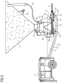
- a silo 1 is set up for storing and dispensing material, in particular dry mortar material.
- this silo 1 comprises a cylindrical upper part and a truncated cone-shaped lower part which thus functions as a funnel.
- a conveyor vessel 3 is connected to the outlet of the silo 1.
- the dry mortar taken from the silo 1 is fed via a conveyor line 5 to the processing device 7, in which the mortar mass required for plastering is produced from the dry mortar with the addition of water and can be taken out for the direct application of the external plaster.
- the conveyor line 5 is designed as a hose line.
- the dry mortar is transported to the plastering machine 7 pneumatically or using compressed air.
- a compressor 11 is connected to the conveyor vessel 3 via a first air line 9 (shown in dashed lines), which supplies compressed air to the conveyor vessel 3.
- the first air line 9 is, as shown in detail in Figure 2 shown, connected to an interior air inlet 13 which is arranged in the outlet-side interior region 15 of a conveyor vessel outlet 17.
- the interior air inlet 13 is designed as a conveyor nozzle which is oriented in the direction of the conveyor vessel outlet 17, so that an air flow can be generated along the conveyor line 5 connected to the conveyor vessel 3.
- a lockable valve 19 which is designed as a pneumatic pinch valve and has a connection 21 for supplying control air via a second air line 23 (shown in dashed lines).
- bypass air inlet 25 Downstream from the conveyor vessel outlet 17 there is a bypass air inlet 25, via which conveying air can be blown into the conveying line 5 even when the valve 19 is closed.
- the bypass air inlet 25 is designed as a conveying nozzle and is connected to the compressor 11 via a third air line 27.
- a fourth air line 29 connects the compressor 11 to another valve 33 designed as a pinch valve for supplying control air.
- a vent line 31 is connected to the conveyor vessel 3 via the further valve 33.
- the passage cross-section of the further valve 33 can be changed pneumatically by supplying the control air.
- a screw conveyor 35 is installed in the lower area of the conveyor vessel 3, which continuously supplies material to the outlet-side inner area 15 during the conveying operation.
- the screw conveyor 35 comprises a conveyor screw 37 which can be rotated about a horizontal axis of rotation and which can be set in a rotary motion by means of an electric or pneumatic drive 39 in order to convey material.
- the transport path of the screw conveyor 35 ends in the outlet-side inner area 15, which is surrounded on the edge by a pipe section. This design serves to promote a well-dosed flow of material that can be transported further via the conveyor line 5 by the introduced conveying air using the Venturi effect.
- the conveyor vessel 3 is filled in batches with dry mortar material from the silo 1.
- a silo flap 41 is opened with the valve 19 closed so that material can fall into the conveyor vessel 3 from above. If necessary, vibrations are generated with the help of a pneumatic or electric vibrator 43 in order to support the flow of material downwards towards the conveyor vessel 3.
- the filled material passes via inclined pouring plates 45 under the influence of gravity into the lower area of the conveyor vessel 3, in which the screw conveyor 35 is arranged. Depending on the density of the filled material, this process typically requires a few seconds, in particular around 10 seconds.
- the silo flap 41 is then closed, the valve 19 is opened and air is introduced via the interior air inlet 13 in order to fluidize the filled material.
- the screw conveyor 35 is activated, for example, three seconds after the silo flap 41 is closed, in particular automatically.
- a pressure sensor measures and monitors the pressure within the conveying line 5, particularly during conveying operation. If this pressure reaches or exceeds a predetermined limit value or a limit value that can be specified via a corresponding user input, for example, which is linked to a blockage, the drive 39 of the screw conveyor 35 is stopped manually or automatically in order to prevent further material supply. In the meantime, conveying air continues to be blown in via the interior air inlet 13 in order to clear the bottleneck in the conveying line 5.
- the limit value generally depends on the nature of the material being conveyed and in particular on its specific weight and on the length of the conveying line 5. In a specific application, the density of the material being conveyed is approximately 1.3 kg/dm 3 . The limit value associated with blockages or bottlenecks in the conveying line 5 can in this case be approximately 1.8 bar.
- the screw drive 35 After reaching or falling below a threshold value that is below the limit value and is typically linked to a pressure that can occur during regular conveying operation, the screw drive 35 is manually or automatically reactivated and operated.
- the threshold value is approximately 1.5 bar.
- a control unit (not shown in detail) is provided in one possible embodiment, which is in a corresponding operative connection with the pressure sensor, the drive 39 and/or the compressor 11.
- the conveyor operation is interrupted by a corresponding user input or automatically, i.e. both the operation of the screw conveyor 35 and the air supply via the interior air inlet 13 are interrupted.
- the valve 19 is closed to fill the conveyor vessel 3.
- conveying air continues to be blown into the conveyor line 5 via the bypass air inlet 25 in order to transport the material contained therein in the meantime towards the processing device 7.
- the valve 33 is opened during filling to release the vent line 31. This measure can prevent material compaction during filling.
- the screw conveyor 35 can be oriented at an angle with respect to the gravitational field or additional pouring plates can be provided within the conveyor vessel 3 for distributing the material fed from the silo 1.
- Another aspect relates to the supply of conveying air via the bypass air inlet 25. This enables the conveyor line 5 to be blown free even when the valve 19 is closed, so that material can continue to be fed to the processing device 7, in particular while the conveyor vessel 3 is being filled. This results in time savings that have a positive effect on the workflow regardless of the further specific design of the conveyor vessel 3. It is therefore intended to provide a further bypass air inlet 25 downstream of the conveyor vessel outlet 17, even in conveyor vessels in which the material transport within the conveyor vessel takes place without the aid of a screw conveyor, for example exclusively under the influence of gravity and/or supplied conveying air.
Landscapes
- Engineering & Computer Science (AREA)
- Mechanical Engineering (AREA)
- Filling Or Emptying Of Bunkers, Hoppers, And Tanks (AREA)
- Screw Conveyors (AREA)
Claims (15)
- Dispositif pour transporter un matériau constitué au moins principalement de particules solides, en particulier un matériau en poudre, par exemple du mortier sec, avec un récipient de transport (3) qui peut être couplé ou est couplé par une ouverture d'entrée à une ouverture de sortie d'un réservoir de stockage, par exemple un silo (1), le récipient de transport (3) présentant une sortie de récipient de transport (17) à laquelle peut être raccordée ou est raccordée une conduite de transport (5), en particulier une conduite flexible, le récipient de transport (3) pouvant être alimenté ou étant alimenté en air de transport pour transporter le matériau à transporter en direction de la sortie de récipient de transport (17), un convoyeur à vis (35) étant disposé au moins partiellement à l'intérieur du récipient de transport (3) pour le transport et le dosage de matériau, dont le trajet de transport mène à une zone intérieure (15) côté sortie du récipient de transport (3), caractérisé en ce qu'une entrée d'air intérieure (13) est disposée pour l'introduction d'air de transport dans la zone intérieure côté sortie de telle manière, que l'air de transport introduit est essentiellement dirigé vers la sortie (17) du récipient de transport, le transport du matériau jusqu'à la zone intérieure (15) côté sortie du récipient de transport (3) étant effectué par le transporteur à vis (35), tandis que le transport du matériau à partir de la zone intérieure (15) côté sortie du récipient de transport (3) est effectué par l'air de transport.
- Dispositif selon la revendication 1, caractérisé en ce que le transporteur à vis (35) comprend, pour le transport du matériau dans la direction axiale, au moins une vis transporteuse hélico dale (37) pouvant tourner autour d'un axe de rotation, qui est disposée sensiblement horizontalement, en particulier par rapport au champ de gravité.
- Dispositif selon la revendication 1 ou 2, caractérisé en ce que la vis transporteuse (37) est entourée, au moins dans la zone intérieure (17) côté sortie, par une section de tube, en particulier cylindrique.
- Dispositif selon l'une des revendications précédentes, caractérisé en ce qu'un entraînement (39) du convoyeur à vis (35) est conçu pour transporter des matériaux ayant un poids spécifique supérieur à 1,3 kg/dm3 .
- Dispositif notamment selon l'une des revendications précédentes, caractérisé en ce qu'à la sortie (17) du récipient de transport est raccordée une conduite de transport (5) comportant une vanne (19) pouvant être fermée, une entrée d'air de dérivation (25) pour l'introduction d'air de transport étant disposée en aval de la vanne (19) de telle sorte que l'air de transport introduit est essentiellement dirigé à l'opposé de la sortie (17) du récipient de transport.
- Dispositif selon la revendication 5, caractérisé en ce qu'une section de passage de la soupape (19) peut être commandée, en particulier commandée pneumatiquement en l'alimentant en air comprimé.
- Dispositif selon l'une des revendications précédentes, caractérisé en ce qu'un capteur de pression est prévu pour détecter et/ou surveiller la pression à l'intérieur de la conduite de transport (5).
- Procédé pour transporter un matériau constitué au moins principalement de particules solides, en particulier un matériau en poudre, par exemple du mortier sec, caractérisé en ce que le transport du matériau s'effectue au moyen d'un dispositif selon l'une des revendications précédentes, le récipient de transport (3) étant rempli par lots de matériau et le transporteur à vis (35) étant ensuite activé pour transporter le matériau du lot dans un mode de transport, en particulier après l'écoulement d'un laps de temps prédéterminé ou prédéfini, et de l'air de transport étant insufflé par l'entrée d'air intérieure (13).
- Procédé selon la revendication 8, caractérisé en ce que l'intervalle de temps est de quelques secondes, en particulier d'environ trois secondes.
- Procédé selon la revendication 8 ou 9, caractérisé en ce que le fonctionnement de transport du transporteur à vis (35) est interrompu, en particulier automatiquement, lorsque la pression dans la conduite de transport (5) dépasse une valeur limite prédéterminée ou prédéfinie, en particulier quelques bars, par exemple environ 1,8 bar, de l'air de transport étant injecté par l'entrée d'air intérieure (13) et/ou par l'entrée d'air de dérivation (25) une fois la valeur limite atteinte.
- Procédé selon l'une quelconque des revendications précédentes 8 à 10, caractérisé en ce que le transporteur à vis (35) pour le transport de matériau en mode de transport fonctionne, en particulier est activé et fonctionne automatiquement, lorsque la pression dans la conduite de transport (5) est inférieure à une valeur seuil prédéterminée ou prédéfinie, qui est en particulier inférieure à la valeur limite et est de quelques bars, par exemple d'environ 1,5 bar.
- Procédé notamment selon l'une des revendications précédentes 8 à 11, caractérisé en ce que la sortie du récipient de transport est fermée au moyen de la vanne (19) pour le remplissage notamment par lots ou par intervalles du récipient de transport (3) avec un matériau, de l'air de transport étant injecté par l'entrée d'air de dérivation (25) pendant le processus de remplissage.
- Procédé selon l'une quelconque des revendications précédentes 8 à 12, caractérisé en ce que l'opération de convoyage du convoyeur à vis (35) et l'injection d'air de convoyage, notamment par l'intermédiaire de l'entrée d'air intérieure (13) et/ou de l'entrée d'air de dérivation (25), sont interrompues, notamment automatiquement, lorsque la pression dans la conduite de convoyage (5) devient inférieure à une valeur minimale associée à une conduite de convoyage (5) vide et/ou à un récipient de convoyage (3) vide.
- Procédé selon la revendication 13, caractérisé en ce que la valeur minimale est inférieure à 1 bar, par exemple d'environ 0,8 bar.
- Procédé selon l'une quelconque des revendications 8 ou 14, caractérisé en ce qu'au moins pour le transport de matériau en mode de transport, de l'air de transport est injecté en continu via l'entrée d'air intérieure (13) et/ou le convoyeur à vis (35) est actionné en continu.
Priority Applications (2)
| Application Number | Priority Date | Filing Date | Title |
|---|---|---|---|
| EP17183046.6A EP3434632B1 (fr) | 2017-07-25 | 2017-07-25 | Dispositif et procédé d'acheminement de matériau constitué d'au moins principalement de particules solides, en particulier poudre, par exemple mortier sec |
| CN201810725958.5A CN109292461B (zh) | 2017-07-25 | 2018-07-04 | 用于输送至少主要由固体颗粒组成的物料的设备和方法 |
Applications Claiming Priority (1)
| Application Number | Priority Date | Filing Date | Title |
|---|---|---|---|
| EP17183046.6A EP3434632B1 (fr) | 2017-07-25 | 2017-07-25 | Dispositif et procédé d'acheminement de matériau constitué d'au moins principalement de particules solides, en particulier poudre, par exemple mortier sec |
Publications (3)
| Publication Number | Publication Date |
|---|---|
| EP3434632A1 EP3434632A1 (fr) | 2019-01-30 |
| EP3434632B1 true EP3434632B1 (fr) | 2024-11-13 |
| EP3434632C0 EP3434632C0 (fr) | 2024-11-13 |
Family
ID=59409213
Family Applications (1)
| Application Number | Title | Priority Date | Filing Date |
|---|---|---|---|
| EP17183046.6A Active EP3434632B1 (fr) | 2017-07-25 | 2017-07-25 | Dispositif et procédé d'acheminement de matériau constitué d'au moins principalement de particules solides, en particulier poudre, par exemple mortier sec |
Country Status (2)
| Country | Link |
|---|---|
| EP (1) | EP3434632B1 (fr) |
| CN (1) | CN109292461B (fr) |
Families Citing this family (2)
| Publication number | Priority date | Publication date | Assignee | Title |
|---|---|---|---|---|
| CN111470323B (zh) * | 2020-05-12 | 2025-03-11 | 伊克斯达(青岛)控股有限公司 | 炭黑输送设备及输送方法 |
| CN120308663B (zh) * | 2025-06-17 | 2025-08-15 | 江苏恒博气力输送设备制造有限公司 | 一种新型气力输送装置 |
Family Cites Families (14)
| Publication number | Priority date | Publication date | Assignee | Title |
|---|---|---|---|---|
| US3778522A (en) * | 1971-07-23 | 1973-12-11 | Gen Mills Inc | Method of texturizing protein |
| CN1017039B (zh) * | 1987-02-24 | 1992-06-17 | 煤气系统有限公司 | 高速螺旋文氏管系统和散料运输法 |
| AT500330B1 (de) * | 2001-10-24 | 2006-11-15 | Mann & Hummel Protec Gmbh | Fördergerät |
| DE102005003620A1 (de) * | 2005-01-26 | 2006-08-03 | Lanxess Deutschland Gmbh | Verfahren und Vorrichtung zur pneumatischen Förderung von schwerfließendem Schüttgut |
| AU2011226842B2 (en) * | 2005-09-29 | 2012-02-09 | National Oilwell Varco, L.P. | Method for conveying drill cuttings |
| EP2297519B1 (fr) * | 2008-06-05 | 2014-05-07 | Kurt Himmelfreundpointner | Procédé et dispositif pour l'acheminement de matériaux transportables dans des réacteurs |
| DE202008013042U1 (de) | 2008-10-02 | 2009-11-19 | Knauf Pft Gmbh & Co.Kg | Vorrichtung zum Fördern von zumindest überwiegend aus Feststoffpartikeln bestehendem Material, insbesondere Pulvermaterial, beispielsweise Trockenmörtel |
| US8926231B2 (en) * | 2009-09-29 | 2015-01-06 | General Electric Company | Solid fuel transporting system for a gasifier |
| CN201890622U (zh) * | 2010-10-25 | 2011-07-06 | 宝山钢铁股份有限公司 | 一种气力输送装置 |
| CN102030191B (zh) * | 2010-12-10 | 2012-11-21 | 浙江工业大学 | 颗粒状固体给料-输送-喷洒一体化装置 |
| CN202163905U (zh) * | 2011-07-05 | 2012-03-14 | 张丹君 | 移动式管道输送系统 |
| CN103964205B (zh) * | 2014-04-30 | 2018-12-07 | 程辉 | 不间断自动配送料气流输送喷射泵 |
| CN105173737A (zh) * | 2015-08-13 | 2015-12-23 | 郑州三迪建筑科技有限公司 | 一种粉粒料正压输送泵 |
| CN106144608A (zh) * | 2016-08-22 | 2016-11-23 | 李福军 | 粉末稳定可控输送装置及方法 |
-
2017
- 2017-07-25 EP EP17183046.6A patent/EP3434632B1/fr active Active
-
2018
- 2018-07-04 CN CN201810725958.5A patent/CN109292461B/zh active Active
Also Published As
| Publication number | Publication date |
|---|---|
| CN109292461A (zh) | 2019-02-01 |
| EP3434632A1 (fr) | 2019-01-30 |
| EP3434632C0 (fr) | 2024-11-13 |
| CN109292461B (zh) | 2022-08-12 |
Similar Documents
| Publication | Publication Date | Title |
|---|---|---|
| EP2072974A1 (fr) | Appareil de laboratoire doté d'un dispositif de guidage de produit de dosage | |
| WO1997017169A1 (fr) | Dispositif pour doser des materiaux granuleux coulants, notamment des grenailles | |
| DE2122858C3 (de) | Einrichtung zum pneumatischen Bilden und Fördern von durch Druckluftpolster voneinander getrennten Materialpfropfen in einer Leitung | |
| DE3145017A1 (de) | Pneumatische foerderanlage | |
| EP1469289A2 (fr) | Dispositif de dosage pour pigments pulvérulants | |
| DE3907361A1 (de) | Pulverdosiergeraet | |
| EP3434632A1 (fr) | Dispositif et procédé d'acheminement de matériau constitué d'au moins principalement de particules solides, en particulier poudre, par exemple mortier sec | |
| WO2017059955A1 (fr) | Procédé et dispositif de transport pour transporter un milieu | |
| EP1427657A1 (fr) | Dispositif et procede pour transporter un produit a transporter de type poussiere, poudre, grains ou granules, d'un recipient de stockage dans un recipient de travail ou de transport ou dans un espace de reception de meme type | |
| EP3568279B1 (fr) | Fabrication additive avec transport pneumatique de produit en vrac par surpression | |
| DE2543379A1 (de) | Vorrichtung zur kontinuierlichen herstellung von angemachtem moertel | |
| DE2425532A1 (de) | Vorrichtung und verfahren zum dosierten austrag stark backender bzw. agglomerationsfreudiger und schwer fluidisierbarer pulver aus behaeltern | |
| EP3468701B1 (fr) | Mélangeur, installation et procédé pour mélanger des materiaux, en particulier des materiaux en vrac, et utilisation dudit mélangeur | |
| DE2340246A1 (de) | Kontinuierliche mischpumpe | |
| DE19539610C2 (de) | Automatische Förderregulierung an pneumatischen Druckförderanlagen | |
| DE102015114674B4 (de) | Verfahren zum Fördern eines trockenen Schüttguts | |
| EP1730059A2 (fr) | Dispositif et procede pour le transport pneumatique de matieres en vrac finement divisees | |
| EP2230004A1 (fr) | Dispositif de revêtement de type à cascade pour matériau poudreux, et procédé associé | |
| EP0867389B1 (fr) | Dispositif et procédé de transport pour matière pulvérulente ou granuleuse | |
| EP0117397A1 (fr) | Procédé pour remplir un extracteur de cuve | |
| DE3330892A1 (de) | Vorrichtung zum spritzen von beton, moertel oder feuerfesten auskleidungsmaterialien | |
| EP1628897A1 (fr) | Dispositif d'alimentation continue d'une conduite d'alimentation pneumatique, en solide pulverulent | |
| EP0117922B1 (fr) | Dispositif pour le transport de matériaux pulvérulents jusqu'à des matériaux à gros grains, notamment des matériaux de remblai dans l'exploitation minière souterraine | |
| EP2848543A1 (fr) | Dispositif et procédé pour remplir un récipient avec un matériau en forme de particules | |
| AT410420B (de) | Anlage zum fördern und trockenspritzen von baustoffgemischen |
Legal Events
| Date | Code | Title | Description |
|---|---|---|---|
| PUAI | Public reference made under article 153(3) epc to a published international application that has entered the european phase |
Free format text: ORIGINAL CODE: 0009012 |
|
| STAA | Information on the status of an ep patent application or granted ep patent |
Free format text: STATUS: THE APPLICATION HAS BEEN PUBLISHED |
|
| AK | Designated contracting states |
Kind code of ref document: A1 Designated state(s): AL AT BE BG CH CY CZ DE DK EE ES FI FR GB GR HR HU IE IS IT LI LT LU LV MC MK MT NL NO PL PT RO RS SE SI SK SM TR |
|
| AX | Request for extension of the european patent |
Extension state: BA ME |
|
| STAA | Information on the status of an ep patent application or granted ep patent |
Free format text: STATUS: REQUEST FOR EXAMINATION WAS MADE |
|
| 17P | Request for examination filed |
Effective date: 20190730 |
|
| RBV | Designated contracting states (corrected) |
Designated state(s): AL AT BE BG CH CY CZ DE DK EE ES FI FR GB GR HR HU IE IS IT LI LT LU LV MC MK MT NL NO PL PT RO RS SE SI SK SM TR |
|
| STAA | Information on the status of an ep patent application or granted ep patent |
Free format text: STATUS: EXAMINATION IS IN PROGRESS |
|
| 17Q | First examination report despatched |
Effective date: 20220511 |
|
| GRAP | Despatch of communication of intention to grant a patent |
Free format text: ORIGINAL CODE: EPIDOSNIGR1 |
|
| STAA | Information on the status of an ep patent application or granted ep patent |
Free format text: STATUS: GRANT OF PATENT IS INTENDED |
|
| INTG | Intention to grant announced |
Effective date: 20240612 |
|
| GRAS | Grant fee paid |
Free format text: ORIGINAL CODE: EPIDOSNIGR3 |
|
| GRAA | (expected) grant |
Free format text: ORIGINAL CODE: 0009210 |
|
| STAA | Information on the status of an ep patent application or granted ep patent |
Free format text: STATUS: THE PATENT HAS BEEN GRANTED |
|
| AK | Designated contracting states |
Kind code of ref document: B1 Designated state(s): AL AT BE BG CH CY CZ DE DK EE ES FI FR GB GR HR HU IE IS IT LI LT LU LV MC MK MT NL NO PL PT RO RS SE SI SK SM TR |
|
| REG | Reference to a national code |
Ref country code: GB Ref legal event code: FG4D Free format text: NOT ENGLISH |
|
| REG | Reference to a national code |
Ref country code: CH Ref legal event code: EP |
|
| REG | Reference to a national code |
Ref country code: IE Ref legal event code: FG4D Free format text: LANGUAGE OF EP DOCUMENT: GERMAN |
|
| REG | Reference to a national code |
Ref country code: DE Ref legal event code: R096 Ref document number: 502017016555 Country of ref document: DE |
|
| U01 | Request for unitary effect filed |
Effective date: 20241212 |
|
| U07 | Unitary effect registered |
Designated state(s): AT BE BG DE DK EE FI FR IT LT LU LV MT NL PT RO SE SI Effective date: 20241219 |
|
| PG25 | Lapsed in a contracting state [announced via postgrant information from national office to epo] |
Ref country code: HR Free format text: LAPSE BECAUSE OF FAILURE TO SUBMIT A TRANSLATION OF THE DESCRIPTION OR TO PAY THE FEE WITHIN THE PRESCRIBED TIME-LIMIT Effective date: 20241113 Ref country code: IS Free format text: LAPSE BECAUSE OF FAILURE TO SUBMIT A TRANSLATION OF THE DESCRIPTION OR TO PAY THE FEE WITHIN THE PRESCRIBED TIME-LIMIT Effective date: 20250313 |
|
| PG25 | Lapsed in a contracting state [announced via postgrant information from national office to epo] |
Ref country code: ES Free format text: LAPSE BECAUSE OF FAILURE TO SUBMIT A TRANSLATION OF THE DESCRIPTION OR TO PAY THE FEE WITHIN THE PRESCRIBED TIME-LIMIT Effective date: 20241113 |
|
| PG25 | Lapsed in a contracting state [announced via postgrant information from national office to epo] |
Ref country code: NO Free format text: LAPSE BECAUSE OF FAILURE TO SUBMIT A TRANSLATION OF THE DESCRIPTION OR TO PAY THE FEE WITHIN THE PRESCRIBED TIME-LIMIT Effective date: 20250213 |
|
| PG25 | Lapsed in a contracting state [announced via postgrant information from national office to epo] |
Ref country code: GR Free format text: LAPSE BECAUSE OF FAILURE TO SUBMIT A TRANSLATION OF THE DESCRIPTION OR TO PAY THE FEE WITHIN THE PRESCRIBED TIME-LIMIT Effective date: 20250214 |
|
| PG25 | Lapsed in a contracting state [announced via postgrant information from national office to epo] |
Ref country code: PL Free format text: LAPSE BECAUSE OF FAILURE TO SUBMIT A TRANSLATION OF THE DESCRIPTION OR TO PAY THE FEE WITHIN THE PRESCRIBED TIME-LIMIT Effective date: 20241113 |
|
| PG25 | Lapsed in a contracting state [announced via postgrant information from national office to epo] |
Ref country code: RS Free format text: LAPSE BECAUSE OF FAILURE TO SUBMIT A TRANSLATION OF THE DESCRIPTION OR TO PAY THE FEE WITHIN THE PRESCRIBED TIME-LIMIT Effective date: 20250213 |
|
| PG25 | Lapsed in a contracting state [announced via postgrant information from national office to epo] |
Ref country code: SM Free format text: LAPSE BECAUSE OF FAILURE TO SUBMIT A TRANSLATION OF THE DESCRIPTION OR TO PAY THE FEE WITHIN THE PRESCRIBED TIME-LIMIT Effective date: 20241113 |
|
| PG25 | Lapsed in a contracting state [announced via postgrant information from national office to epo] |
Ref country code: SK Free format text: LAPSE BECAUSE OF FAILURE TO SUBMIT A TRANSLATION OF THE DESCRIPTION OR TO PAY THE FEE WITHIN THE PRESCRIBED TIME-LIMIT Effective date: 20241113 |
|
| PG25 | Lapsed in a contracting state [announced via postgrant information from national office to epo] |
Ref country code: CZ Free format text: LAPSE BECAUSE OF FAILURE TO SUBMIT A TRANSLATION OF THE DESCRIPTION OR TO PAY THE FEE WITHIN THE PRESCRIBED TIME-LIMIT Effective date: 20241113 |
|
| U20 | Renewal fee for the european patent with unitary effect paid |
Year of fee payment: 9 Effective date: 20250728 |
|
| PLBE | No opposition filed within time limit |
Free format text: ORIGINAL CODE: 0009261 |
|
| STAA | Information on the status of an ep patent application or granted ep patent |
Free format text: STATUS: NO OPPOSITION FILED WITHIN TIME LIMIT |
|
| 26N | No opposition filed |
Effective date: 20250814 |
|
| REG | Reference to a national code |
Ref country code: CH Ref legal event code: H13 Free format text: ST27 STATUS EVENT CODE: U-0-0-H10-H13 (AS PROVIDED BY THE NATIONAL OFFICE) Effective date: 20260224 |
|
| GBPC | Gb: european patent ceased through non-payment of renewal fee |
Effective date: 20250725 |
|
| PG25 | Lapsed in a contracting state [announced via postgrant information from national office to epo] |
Ref country code: GB Free format text: LAPSE BECAUSE OF NON-PAYMENT OF DUE FEES Effective date: 20250725 |
|
| PG25 | Lapsed in a contracting state [announced via postgrant information from national office to epo] |
Ref country code: CH Free format text: LAPSE BECAUSE OF NON-PAYMENT OF DUE FEES Effective date: 20250731 |