EP3434862A1 - Variabler durchflussbegrenzer zum einsatz in einem untergrundbohrloch - Google Patents
Variabler durchflussbegrenzer zum einsatz in einem untergrundbohrloch Download PDFInfo
- Publication number
- EP3434862A1 EP3434862A1 EP18187016.3A EP18187016A EP3434862A1 EP 3434862 A1 EP3434862 A1 EP 3434862A1 EP 18187016 A EP18187016 A EP 18187016A EP 3434862 A1 EP3434862 A1 EP 3434862A1
- Authority
- EP
- European Patent Office
- Prior art keywords
- fluid composition
- flow
- outlet
- fluid
- well
- Prior art date
- Legal status (The legal status is an assumption and is not a legal conclusion. Google has not performed a legal analysis and makes no representation as to the accuracy of the status listed.)
- Granted
Links
Images




Classifications
-
- E—FIXED CONSTRUCTIONS
- E21—EARTH OR ROCK DRILLING; MINING
- E21B—EARTH OR ROCK DRILLING; OBTAINING OIL, GAS, WATER, SOLUBLE OR MELTABLE MATERIALS OR A SLURRY OF MINERALS FROM WELLS
- E21B43/00—Methods or apparatus for obtaining oil, gas, water, soluble or meltable materials or a slurry of minerals from wells
- E21B43/12—Methods or apparatus for controlling the flow of the obtained fluid to or in wells
-
- E—FIXED CONSTRUCTIONS
- E21—EARTH OR ROCK DRILLING; MINING
- E21B—EARTH OR ROCK DRILLING; OBTAINING OIL, GAS, WATER, SOLUBLE OR MELTABLE MATERIALS OR A SLURRY OF MINERALS FROM WELLS
- E21B34/00—Valve arrangements for boreholes or wells
- E21B34/06—Valve arrangements for boreholes or wells in wells
- E21B34/08—Valve arrangements for boreholes or wells in wells responsive to flow or pressure of the fluid obtained
-
- E—FIXED CONSTRUCTIONS
- E21—EARTH OR ROCK DRILLING; MINING
- E21B—EARTH OR ROCK DRILLING; OBTAINING OIL, GAS, WATER, SOLUBLE OR MELTABLE MATERIALS OR A SLURRY OF MINERALS FROM WELLS
- E21B43/00—Methods or apparatus for obtaining oil, gas, water, soluble or meltable materials or a slurry of minerals from wells
- E21B43/14—Obtaining from a multiple-zone well
-
- E—FIXED CONSTRUCTIONS
- E21—EARTH OR ROCK DRILLING; MINING
- E21B—EARTH OR ROCK DRILLING; OBTAINING OIL, GAS, WATER, SOLUBLE OR MELTABLE MATERIALS OR A SLURRY OF MINERALS FROM WELLS
- E21B47/00—Survey of boreholes or wells
- E21B47/12—Means for transmitting measuring-signals or control signals from the well to the surface, or from the surface to the well, e.g. for logging while drilling
- E21B47/14—Means for transmitting measuring-signals or control signals from the well to the surface, or from the surface to the well, e.g. for logging while drilling using acoustic waves
- E21B47/18—Means for transmitting measuring-signals or control signals from the well to the surface, or from the surface to the well, e.g. for logging while drilling using acoustic waves through the well fluid, e.g. mud pressure pulse telemetry
-
- E—FIXED CONSTRUCTIONS
- E21—EARTH OR ROCK DRILLING; MINING
- E21B—EARTH OR ROCK DRILLING; OBTAINING OIL, GAS, WATER, SOLUBLE OR MELTABLE MATERIALS OR A SLURRY OF MINERALS FROM WELLS
- E21B2200/00—Special features related to earth drilling for obtaining oil, gas or water
- E21B2200/02—Down-hole chokes or valves for variably regulating fluid flow
-
- Y—GENERAL TAGGING OF NEW TECHNOLOGICAL DEVELOPMENTS; GENERAL TAGGING OF CROSS-SECTIONAL TECHNOLOGIES SPANNING OVER SEVERAL SECTIONS OF THE IPC; TECHNICAL SUBJECTS COVERED BY FORMER USPC CROSS-REFERENCE ART COLLECTIONS [XRACs] AND DIGESTS
- Y10—TECHNICAL SUBJECTS COVERED BY FORMER USPC
- Y10T—TECHNICAL SUBJECTS COVERED BY FORMER US CLASSIFICATION
- Y10T137/00—Fluid handling
- Y10T137/206—Flow affected by fluid contact, energy field or coanda effect [e.g., pure fluid device or system]
- Y10T137/2087—Means to cause rotational flow of fluid [e.g., vortex generator]
-
- Y—GENERAL TAGGING OF NEW TECHNOLOGICAL DEVELOPMENTS; GENERAL TAGGING OF CROSS-SECTIONAL TECHNOLOGIES SPANNING OVER SEVERAL SECTIONS OF THE IPC; TECHNICAL SUBJECTS COVERED BY FORMER USPC CROSS-REFERENCE ART COLLECTIONS [XRACs] AND DIGESTS
- Y10—TECHNICAL SUBJECTS COVERED BY FORMER USPC
- Y10T—TECHNICAL SUBJECTS COVERED BY FORMER US CLASSIFICATION
- Y10T137/00—Fluid handling
- Y10T137/206—Flow affected by fluid contact, energy field or coanda effect [e.g., pure fluid device or system]
- Y10T137/2087—Means to cause rotational flow of fluid [e.g., vortex generator]
- Y10T137/2109—By tangential input to axial output [e.g., vortex amplifier]
Definitions
- This disclosure relates generally to equipment utilized and operations performed in conjunction with a subterranean well and, in an example described below, more particularly provides a variable flow restrictor.
- variable flow resistance system which brings improvements to the art of variably restricting fluid flow in a well.
- a flow chamber is provided with structures which cause a restriction to flow through the chamber to increase as a ratio of undesired to desired fluid in a fluid composition increases.
- this disclosure provides to the art a variable flow resistance system for use in a subterranean well.
- the system can include a flow chamber through which a fluid composition flows.
- the chamber has at least one inlet, an outlet, and at least one structure spirally oriented relative to the outlet.
- the structure induces spiral flow of the fluid composition about the outlet.
- a variable flow resistance system for use in a subterranean well can include a flow chamber including an outlet, at least one structure which induces spiral flow of a fluid composition about the outlet, and at least one other structure which impedes a change in direction of flow of the fluid composition radially toward the outlet.
- FIG. 1 Representatively illustrated in FIG. 1 is a well system 10 which can embody principles of this disclosure.
- a wellbore 12 has a generally vertical uncased section 14 extending downwardly from casing 16, as well as a generally horizontal uncased section 18 extending through an earth formation 20.
- a tubular string 22 (such as a production tubing string) is installed in the wellbore 12. Interconnected in the tubular string 22 are multiple well screens 24, variable flow resistance systems 25 and packers 26.
- the packers 26 seal off an annulus 28 formed radially between the tubular string 22 and the wellbore section 18. In this manner, fluids 30 may be produced from multiple intervals or zones of the formation 20 via isolated portions of the annulus 28 between adjacent pairs of the packers 26.
- a well screen 24 and a variable flow resistance system 25 are interconnected in the tubular string 22.
- the well screen 24 filters the fluids 30 flowing into the tubular string 22 from the annulus 28.
- the variable flow resistance system 25 variably restricts flow of the fluids 30 into the tubular string 22, based on certain characteristics of the fluids.
- the wellbore 12 it is not necessary in keeping with the principles of this disclosure for the wellbore 12 to include a generally vertical wellbore section 14 or a generally horizontal wellbore section 18. It is not necessary for fluids 30 to be only produced from the formation 20 since, in other examples, fluids could be injected into a formation, fluids could be both injected into and produced from a formation, etc.
- variable flow resistance system 25 It is not necessary for one each of the well screen 24 and variable flow resistance system 25 to be positioned between each adjacent pair of the packers 26. It is not necessary for a single variable flow resistance system 25 to be used in conjunction with a single well screen 24. Any number, arrangement and/or combination of these components may be used.
- variable flow resistance system 25 it is not necessary for any variable flow resistance system 25 to be used with a well screen 24.
- the injected fluid could be flowed through a variable flow resistance system 25, without also flowing through a well screen 24.
- variable flow resistance systems 25, packers 26 or any other components of the tubular string 22 it is not necessary for the well screens 24, variable flow resistance systems 25, packers 26 or any other components of the tubular string 22 to be positioned in uncased sections 14, 18 of the wellbore 12. Any section of the wellbore 12 may be cased or uncased, and any portion of the tubular string 22 may be positioned in an uncased or cased section of the wellbore, in keeping with the principles of this disclosure.
- variable flow resistance systems 25 can provide these benefits by increasing resistance to flow if a fluid velocity increases beyond a selected level (e.g., to thereby balance flow among zones, prevent water or gas coning, etc.), or increasing resistance to flow if a fluid viscosity decreases below a selected level (e.g., to thereby restrict flow of an undesired fluid, such as water or gas, in an oil producing well).
- Whether a fluid is a desired or an undesired fluid depends on the purpose of the production or injection operation being conducted. For example, if it is desired to produce oil from a well, but not to produce water or gas, then oil is a desired fluid and water and gas are undesired fluids.
- a fluid composition 36 (which can include one or more fluids, such as oil and water, liquid water and steam, oil and gas, gas and water, oil, water and gas, etc.) flows into the well screen 24, is thereby filtered, and then flows into an inlet 38 of the variable flow resistance system 25.
- a fluid composition can include one or more undesired or desired fluids. Both steam and water can be combined in a fluid composition. As another example, oil, water and/or gas can be combined in a fluid composition.
- variable flow resistance system 25 Flow of the fluid composition 36 through the variable flow resistance system 25 is resisted based on one or more characteristics (such as viscosity, velocity, etc.) of the fluid composition.
- the fluid composition 36 is then discharged from the variable flow resistance system 25 to an interior of the tubular string 22 via an outlet 40.
- the well screen 24 may not be used in conjunction with the variable flow resistance system 25 (e.g., in injection operations), the fluid composition 36 could flow in an opposite direction through the various elements of the well system 10 (e.g., in injection operations), a single variable flow resistance system could be used in conjunction with multiple well screens, multiple variable flow resistance systems could be used with one or more well screens, the fluid composition could be received from or discharged into regions of a well other than an annulus or a tubular string, the fluid composition could flow through the variable flow resistance system prior to flowing through the well screen, any other components could be interconnected upstream or downstream of the well screen and/or variable flow resistance system, etc.
- the principles of this disclosure are not limited at all to the details of the example depicted in FIG. 2 and described herein.
- well screen 24 depicted in FIG. 2 is of the type known to those skilled in the art as a wire-wrapped well screen, any other types or combinations of well screens (such as sintered, expanded, pre-packed, wire mesh, etc.) may be used in other examples. Additional components (such as shrouds, shunt tubes, lines, instrumentation, sensors, inflow control devices, etc.) may also be used, if desired.
- variable flow resistance system 25 is depicted in simplified form in FIG. 2 , but in a preferred example, the system can include various passages and devices for performing various functions, as described more fully below.
- the system 25 preferably at least partially extends circumferentially about the tubular string 22, or the system may be formed in a wall of a tubular structure interconnected as part of the tubular string.
- the system 25 may not extend circumferentially about a tubular string or be formed in a wall of a tubular structure.
- the system 25 could be formed in a flat structure, etc.
- the system 25 could be in a separate housing that is attached to the tubular string 22, or it could be oriented so that the axis of the outlet 40 is parallel to the axis of the tubular string.
- the system 25 could be on a logging string or attached to a device that is not tubular in shape. Any orientation or configuration of the system 25 may be used in keeping with the principles of this disclosure.
- FIGS. 3A & B more detailed cross-sectional views of one example of the system 25 is representatively illustrated.
- the system 25 is depicted in FIGS. 3A & B as if it is planar in configuration, but the system could instead extend circumferentially, such as in a sidewall of tubular member, if desired.
- FIG. 3A depicts the variable flow resistance system 25 with the fluid composition 36 flowing through a flow chamber 42 between the inlet 38 and the outlet 40.
- the fluid composition 36 has a relatively low viscosity and/or a relatively high velocity. For example, if gas or water is an undesired fluid and oil is a desired fluid, then the fluid composition 36 in FIG. 3A has a relatively high ratio of undesired fluid to desired fluid.
- the flow chamber 42 is provided with structures 44 which induce a spiraling flow of the fluid composition 36 about the outlet 40. That is, the fluid composition 36 is made to flow somewhat circularly about, and somewhat radially toward, the outlet 40.
- the structures 44 also impede a change in direction of the fluid composition 36 radially toward the outlet 40.
- the spiral flow of the fluid composition 36 induced by the structures 44 does have both a circular and a radial component, the structures preferably impede an increase in the radial component.
- the structures 44 are spaced apart from each other in the direction of flow of the fluid composition 36.
- the spacing between the structures 44 preferably decreases incrementally in the direction of flow of the fluid composition 36.
- FIG. 3A Two entrances 46 to the chamber 42 are depicted in FIG. 3A , with each entrance having a series of the spaced apart structures 44 associated therewith. However, it will be appreciated that any number of entrances 46 and structures 44 may be provided in keeping with the principles of this disclosure.
- Additional structures 48 are provided in the chamber 42 for impeding a change toward radial flow of the fluid composition 36. As depicted in FIG. 3A , the structures 48 are circumferentially and radially spaced apart from each other.
- the spacings between the structures 44, 48 do eventually allow the fluid composition 36 to flow to the outlet 40, but energy is dissipated due to the spiraling and circular flow of the fluid composition about the outlet, and so a relatively large resistance to flow is experienced by the fluid composition.
- this resistance to flow will increase.
- the viscosity of the fluid composition 36 increases and/or as the velocity of the fluid composition decreases (e.g., due to an increased ratio of desired to undesired fluids in the fluid composition), this resistance to flow will decrease.
- the system 25 is depicted with such an increased ratio of desired to undesired fluids in the fluid composition 36. Having a higher viscosity and/or lower velocity, the fluid composition 36 is able to more readily flow through the spacings between the structures 44, 48.
- the fluid composition 36 flows much more directly to the outlet 40 in the FIG. 3B example, as compared to the FIG. 3A example.
- the energy dissipation and resistance to flow is much less in the FIG. 3B example, as compared to the FIG. 3A example.
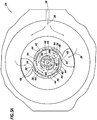
- variable flow resistance system 25 another configuration of the variable flow resistance system 25 is representatively illustrated.
- this configuration there are many more entrances 46 to the chamber 42 as compared to the configuration of FIGS. 3A & B , and there are two radially spaced apart sets of the spiral flow-inducing structures 44.
- FIG. 4 another configuration of the variable flow resistance system 25 is representatively illustrated.
- this configuration there are many more entrances 46 to the chamber 42 as compared to the configuration of FIGS. 3A & B , and there are two radially spaced apart sets of the spiral flow-inducing structures 44.
- the resistance to flow through the system 25 of FIG. 4 will increase as the viscosity of the fluid composition 36 decreases and/or as the velocity of the fluid composition increases. Conversely, the resistance to flow through the system 25 of FIG. 4 will decrease as the viscosity of the fluid composition 36 increases and/or as the velocity of the fluid composition decreases.
- the structures 44 and/or 48 may be formed as vanes or as recesses on one or more walls of the chamber 42. If formed as vanes, the structures 44 and/or 48 may extend outwardly from the chamber 42 wall(s). If formed as recesses, the structures 44 and/or 48 may extend inwardly from the chamber 42 wall(s).
- the functions of inducing a desired direction of flow of the fluid composition 36, or of resisting a change in direction of the fluid composition flow, may be performed with any types, numbers, spacings or configurations of structures.
- variable flow resistance system 25 examples described above operate autonomously, automatically and without any moving parts to reliably regulate flow between a formation 20 and an interior of a tubular string 22.
- variable flow resistance system 25 for use in a subterranean well.
- the system 25 can include a flow chamber 42 through which a fluid composition 36 flows.
- the chamber 42 has at least one inlet 38, an outlet 40, and at least one structure 44 spirally oriented relative to the outlet 40, whereby the structure 44 induces spiral flow of the fluid composition 36 about the outlet 40.
- a variable flow resistance system 25 described above comprises a flow chamber 42 including an outlet 40, at least one structure 44 which induces spiral flow of a fluid composition 36 about the outlet 40, and at least one other structure 48 which impedes a change in direction of flow of the fluid composition 36 radially toward the outlet 40.
- the fluid composition 36 preferably flows through the flow chamber 42 in the well.
- the structure 48 increasingly impedes the change in direction radially toward the outlet 40 in response to at least one of a) increased velocity of the fluid composition 36, b) decreased viscosity of the fluid composition 36, and c) a reduced ratio of desired fluid to undesired fluid in the fluid composition 36.
- the structure 44 and/or 48 can comprises at least one of a vane and a recess.
- the structure 44 and/or 48 can project at least one of inwardly and outwardly relative to a wall of the chamber 42.
- the structure 44 and/or 48 can comprise multiple spaced apart structures. A spacing between adjacent structures 44 may decrease in a direction of spiral flow of the fluid composition 36.
- the fluid composition 36 preferably flows more directly to the outlet 40 as a viscosity of the fluid composition 36 increases, as a velocity of the fluid composition 36 decreases, and/or as a ratio of desired fluid to undesired fluid in the fluid composition 36 increases.
Landscapes
- Engineering & Computer Science (AREA)
- Geology (AREA)
- Life Sciences & Earth Sciences (AREA)
- Mining & Mineral Resources (AREA)
- Physics & Mathematics (AREA)
- Geochemistry & Mineralogy (AREA)
- Fluid Mechanics (AREA)
- General Life Sciences & Earth Sciences (AREA)
- Environmental & Geological Engineering (AREA)
- Acoustics & Sound (AREA)
- Remote Sensing (AREA)
- Geophysics (AREA)
- Pipe Accessories (AREA)
- Rotary Pumps (AREA)
- Pipeline Systems (AREA)
- Earth Drilling (AREA)
Applications Claiming Priority (3)
| Application Number | Priority Date | Filing Date | Title |
|---|---|---|---|
| US12/869,836 US8356668B2 (en) | 2010-08-27 | 2010-08-27 | Variable flow restrictor for use in a subterranean well |
| EP11820391.8A EP2609286B1 (de) | 2010-08-27 | 2011-08-16 | Variabler durchflussbegrenzer zum einsatz in einem untergrundbohrloch |
| PCT/US2011/047925 WO2012027157A1 (en) | 2010-08-27 | 2011-08-16 | Variable flow restrictor for use in a subterranean well |
Related Parent Applications (2)
| Application Number | Title | Priority Date | Filing Date |
|---|---|---|---|
| EP11820391.8A Division EP2609286B1 (de) | 2010-08-27 | 2011-08-16 | Variabler durchflussbegrenzer zum einsatz in einem untergrundbohrloch |
| EP11820391.8A Division-Into EP2609286B1 (de) | 2010-08-27 | 2011-08-16 | Variabler durchflussbegrenzer zum einsatz in einem untergrundbohrloch |
Publications (2)
| Publication Number | Publication Date |
|---|---|
| EP3434862A1 true EP3434862A1 (de) | 2019-01-30 |
| EP3434862B1 EP3434862B1 (de) | 2020-12-30 |
Family
ID=45695609
Family Applications (2)
| Application Number | Title | Priority Date | Filing Date |
|---|---|---|---|
| EP11820391.8A Active EP2609286B1 (de) | 2010-08-27 | 2011-08-16 | Variabler durchflussbegrenzer zum einsatz in einem untergrundbohrloch |
| EP18187016.3A Active EP3434862B1 (de) | 2010-08-27 | 2011-08-16 | Variabler durchflussbegrenzer zum einsatz in einem untergrundbohrloch |
Family Applications Before (1)
| Application Number | Title | Priority Date | Filing Date |
|---|---|---|---|
| EP11820391.8A Active EP2609286B1 (de) | 2010-08-27 | 2011-08-16 | Variabler durchflussbegrenzer zum einsatz in einem untergrundbohrloch |
Country Status (12)
| Country | Link |
|---|---|
| US (2) | US8356668B2 (de) |
| EP (2) | EP2609286B1 (de) |
| CN (1) | CN103080467B (de) |
| AU (1) | AU2011293751B2 (de) |
| BR (1) | BR112013004782B1 (de) |
| CA (1) | CA2808080C (de) |
| CO (1) | CO6650403A2 (de) |
| MX (1) | MX2013002200A (de) |
| MY (1) | MY153827A (de) |
| RU (1) | RU2532410C1 (de) |
| SG (1) | SG187960A1 (de) |
| WO (1) | WO2012027157A1 (de) |
Families Citing this family (65)
| Publication number | Priority date | Publication date | Assignee | Title |
|---|---|---|---|---|
| US8893804B2 (en) | 2009-08-18 | 2014-11-25 | Halliburton Energy Services, Inc. | Alternating flow resistance increases and decreases for propagating pressure pulses in a subterranean well |
| US8235128B2 (en) * | 2009-08-18 | 2012-08-07 | Halliburton Energy Services, Inc. | Flow path control based on fluid characteristics to thereby variably resist flow in a subterranean well |
| US8276669B2 (en) | 2010-06-02 | 2012-10-02 | Halliburton Energy Services, Inc. | Variable flow resistance system with circulation inducing structure therein to variably resist flow in a subterranean well |
| US9109423B2 (en) | 2009-08-18 | 2015-08-18 | Halliburton Energy Services, Inc. | Apparatus for autonomous downhole fluid selection with pathway dependent resistance system |
| US8839871B2 (en) | 2010-01-15 | 2014-09-23 | Halliburton Energy Services, Inc. | Well tools operable via thermal expansion resulting from reactive materials |
| US8708050B2 (en) | 2010-04-29 | 2014-04-29 | Halliburton Energy Services, Inc. | Method and apparatus for controlling fluid flow using movable flow diverter assembly |
| US8356668B2 (en) | 2010-08-27 | 2013-01-22 | Halliburton Energy Services, Inc. | Variable flow restrictor for use in a subterranean well |
| US8430130B2 (en) | 2010-09-10 | 2013-04-30 | Halliburton Energy Services, Inc. | Series configured variable flow restrictors for use in a subterranean well |
| US8950502B2 (en) | 2010-09-10 | 2015-02-10 | Halliburton Energy Services, Inc. | Series configured variable flow restrictors for use in a subterranean well |
| US8851180B2 (en) | 2010-09-14 | 2014-10-07 | Halliburton Energy Services, Inc. | Self-releasing plug for use in a subterranean well |
| US8474533B2 (en) | 2010-12-07 | 2013-07-02 | Halliburton Energy Services, Inc. | Gas generator for pressurizing downhole samples |
| MY164163A (en) | 2011-04-08 | 2017-11-30 | Halliburton Energy Services Inc | Method and apparatus for controlling fluid flow in an autonomous valve using a sticky switch |
| US8678035B2 (en) | 2011-04-11 | 2014-03-25 | Halliburton Energy Services, Inc. | Selectively variable flow restrictor for use in a subterranean well |
| US8596366B2 (en) | 2011-09-27 | 2013-12-03 | Halliburton Energy Services, Inc. | Wellbore flow control devices comprising coupled flow regulating assemblies and methods for use thereof |
| BR112014007245B8 (pt) | 2011-09-27 | 2021-07-20 | Halliburton Energy Services Inc | dispositivos de controle de fluxo do furo do poço compreendendo montagens acopladas regulando o fluxo e métodos para uso destas |
| SG2014010037A (en) | 2011-10-31 | 2014-05-29 | Halliburton Energy Services Inc | Autonomous fluid control device having a reciprocating valve for downhole fluid selection |
| CA2848963C (en) | 2011-10-31 | 2015-06-02 | Halliburton Energy Services, Inc | Autonomous fluid control device having a movable valve plate for downhole fluid selection |
| US8739880B2 (en) | 2011-11-07 | 2014-06-03 | Halliburton Energy Services, P.C. | Fluid discrimination for use with a subterranean well |
| US9506320B2 (en) | 2011-11-07 | 2016-11-29 | Halliburton Energy Services, Inc. | Variable flow resistance for use with a subterranean well |
| SG11201401545UA (en) | 2011-11-10 | 2014-05-29 | Halliburton Energy Services Inc | Rotational motion-inducing variable flow resistance systems having a sidewall fluid outlet and methods for use thereof in a subterranean formation |
| US8684094B2 (en) | 2011-11-14 | 2014-04-01 | Halliburton Energy Services, Inc. | Preventing flow of undesired fluid through a variable flow resistance system in a well |
| CA2853032C (en) * | 2011-12-16 | 2016-11-29 | Halliburton Energy Services, Inc. | Fluid flow control |
| US9038741B2 (en) | 2012-04-10 | 2015-05-26 | Halliburton Energy Services, Inc. | Adjustable flow control device |
| CN104246118A (zh) | 2012-04-18 | 2014-12-24 | 哈利伯顿能源服务公司 | 流动控制装置的设备、系统和方法 |
| CN104334827A (zh) * | 2012-06-28 | 2015-02-04 | 哈利伯顿能源服务公司 | 带有流入控制的可膨胀筛组件 |
| US9151143B2 (en) | 2012-07-19 | 2015-10-06 | Halliburton Energy Services, Inc. | Sacrificial plug for use with a well screen assembly |
| WO2014051557A1 (en) | 2012-09-26 | 2014-04-03 | Halliburton Energy Services, Inc. | Multiple zone integrated intelligent well completion |
| US9404349B2 (en) | 2012-10-22 | 2016-08-02 | Halliburton Energy Services, Inc. | Autonomous fluid control system having a fluid diode |
| US9169705B2 (en) | 2012-10-25 | 2015-10-27 | Halliburton Energy Services, Inc. | Pressure relief-assisted packer |
| US9695654B2 (en) | 2012-12-03 | 2017-07-04 | Halliburton Energy Services, Inc. | Wellhead flowback control system and method |
| US9127526B2 (en) | 2012-12-03 | 2015-09-08 | Halliburton Energy Services, Inc. | Fast pressure protection system and method |
| US8936094B2 (en) | 2012-12-20 | 2015-01-20 | Halliburton Energy Services, Inc. | Rotational motion-inducing flow control devices and methods of use |
| CN104487717B (zh) * | 2012-12-27 | 2017-05-17 | 嚜祂·邀媧攀崑 | 产生流体漩涡流的设备 |
| US9371720B2 (en) | 2013-01-25 | 2016-06-21 | Halliburton Energy Services, Inc. | Autonomous inflow control device having a surface coating |
| WO2014116236A1 (en) | 2013-01-25 | 2014-07-31 | Halliburton Energy Services, Inc. | Autonomous inflow control device having a surface coating |
| SG11201504001TA (en) | 2013-01-29 | 2015-06-29 | Halliburton Energy Services Inc | Magnetic valve assembly |
| US9587486B2 (en) | 2013-02-28 | 2017-03-07 | Halliburton Energy Services, Inc. | Method and apparatus for magnetic pulse signature actuation |
| US9587487B2 (en) | 2013-03-12 | 2017-03-07 | Halliburton Energy Services, Inc. | Wellbore servicing tools, systems and methods utilizing near-field communication |
| US9284817B2 (en) | 2013-03-14 | 2016-03-15 | Halliburton Energy Services, Inc. | Dual magnetic sensor actuation assembly |
| CA2903316A1 (en) | 2013-04-05 | 2014-10-09 | Halliburton Energy Services, Inc. | Controlling flow in a wellbore |
| US9752414B2 (en) | 2013-05-31 | 2017-09-05 | Halliburton Energy Services, Inc. | Wellbore servicing tools, systems and methods utilizing downhole wireless switches |
| US20150075770A1 (en) | 2013-05-31 | 2015-03-19 | Michael Linley Fripp | Wireless activation of wellbore tools |
| US10132136B2 (en) | 2013-07-19 | 2018-11-20 | Halliburton Energy Services, Inc. | Downhole fluid flow control system and method having autonomous closure |
| GB2530672B (en) * | 2013-07-19 | 2020-02-12 | Halliburton Energy Services Inc | Downhole fluid flow control system and method having autonomous closure |
| WO2015031745A1 (en) * | 2013-08-29 | 2015-03-05 | Schlumberger Canada Limited | Autonomous flow control system and methodology |
| NO346964B1 (en) | 2013-12-31 | 2023-03-20 | Halliburton Energy Services Inc | Flow guides for regulating pressure change in hydraulically-actuated downhole tools |
| CN105089570B (zh) * | 2014-05-12 | 2018-12-28 | 中国石油化工股份有限公司 | 用于采油系统的控水装置 |
| CA2959502A1 (en) * | 2014-08-29 | 2016-03-03 | Schlumberger Canada Limited | Autonomous flow control system and methodology |
| CN107076184B (zh) * | 2014-09-29 | 2019-02-12 | 樂那拉·邀媧攀崑 | 用于产生流体的旋流的装置 |
| CN105626003A (zh) * | 2014-11-06 | 2016-06-01 | 中国石油化工股份有限公司 | 一种用于调节地层流体的控制装置 |
| AU2014412711B2 (en) | 2014-11-25 | 2018-05-31 | Halliburton Energy Services, Inc. | Wireless activation of wellbore tools |
| US9976385B2 (en) * | 2015-06-16 | 2018-05-22 | Baker Hughes, A Ge Company, Llc | Velocity switch for inflow control devices and methods for using same |
| WO2017058196A1 (en) * | 2015-09-30 | 2017-04-06 | Floway, Inc. | Downhole fluid flow control system and method having autonomous flow control |
| US12553312B2 (en) | 2017-12-27 | 2026-02-17 | Floway Innovations, Inc. | Autonomous flow control systems having bypass functionality |
| US10060221B1 (en) | 2017-12-27 | 2018-08-28 | Floway, Inc. | Differential pressure switch operated downhole fluid flow control system |
| US12104458B2 (en) | 2017-12-27 | 2024-10-01 | Floway Innovations, Inc. | Adaptive fluid switches having a temporary configuration |
| WO2019209789A1 (en) | 2018-04-27 | 2019-10-31 | Amsted Rail Company, Inc. | Railway truck assembly having friction assist side bearings |
| CN109184628B (zh) * | 2018-08-23 | 2020-11-06 | 中国海洋石油集团有限公司 | 一种可充填自适应型控水筛管 |
| CN111119804A (zh) * | 2018-10-31 | 2020-05-08 | 中国石油化工股份有限公司 | 一种流体流入控制装置 |
| RU2738045C1 (ru) * | 2020-07-21 | 2020-12-07 | Сергей Евгеньевич Варламов | Устройство контроля притока |
| AU2022274752A1 (en) | 2021-05-12 | 2023-11-30 | Schlumberger Technology B.V. | Autonomous inflow control device system and method |
| US11692418B2 (en) | 2021-06-18 | 2023-07-04 | Baker Hughes Oilfield Operations Llc | Inflow control device, method and system |
| US12305480B2 (en) | 2022-05-31 | 2025-05-20 | Saudi Arabian Oil Company | Producing gas through variable bore production tubing |
| US12116872B1 (en) | 2023-04-11 | 2024-10-15 | Halliburton Energy Services, Inc. | Downhole flow control device with turbine chamber insert |
| US12385366B1 (en) * | 2024-03-25 | 2025-08-12 | Halliburton Energy Services, Inc. | Vortex filtration for debris-sensitive components in a well |
Citations (6)
| Publication number | Priority date | Publication date | Assignee | Title |
|---|---|---|---|---|
| US1517598A (en) * | 1921-09-01 | 1924-12-02 | Stevenson John William | Apparatus for spraying fluids and mixing the same |
| US3198214A (en) * | 1962-10-30 | 1965-08-03 | R I V Anstalt Zur Verwaltung V | Fluid regulator |
| US3474670A (en) * | 1965-06-28 | 1969-10-28 | Honeywell Inc | Pure fluid control apparatus |
| US3515160A (en) * | 1967-10-19 | 1970-06-02 | Bailey Meter Co | Multiple input fluid element |
| US20050173336A1 (en) * | 2001-06-12 | 2005-08-11 | Johnny Arnaud | Methods and apparatus for enhancing venturi suction in eductor mixers |
| EP2392771A2 (de) * | 2010-06-02 | 2011-12-07 | Halliburton Energy Services, Inc. | System mit variablem Strömungswiderstand mit Zirkulationsinduzierungsstruktur zum variablen Entgegenwirken von Strömung in einem unterirdischen Bohrloch |
Family Cites Families (111)
| Publication number | Priority date | Publication date | Assignee | Title |
|---|---|---|---|---|
| US3091393A (en) | 1961-07-05 | 1963-05-28 | Honeywell Regulator Co | Fluid amplifier mixing control system |
| US3256899A (en) | 1962-11-26 | 1966-06-21 | Bowles Eng Corp | Rotational-to-linear flow converter |
| US3216439A (en) | 1962-12-18 | 1965-11-09 | Bowles Eng Corp | External vortex transformer |
| US3233621A (en) | 1963-01-31 | 1966-02-08 | Bowles Eng Corp | Vortex controlled fluid amplifier |
| US3282279A (en) | 1963-12-10 | 1966-11-01 | Bowles Eng Corp | Input and control systems for staged fluid amplifiers |
| US3461897A (en) | 1965-12-17 | 1969-08-19 | Aviat Electric Ltd | Vortex vent fluid diode |
| GB1180557A (en) | 1966-06-20 | 1970-02-04 | Dowty Fuel Syst Ltd | Fluid Switch and Proportional Amplifier |
| GB1208280A (en) | 1967-05-26 | 1970-10-14 | Dowty Fuel Syst Ltd | Pressure ratio sensing device |
| US3537466A (en) | 1967-11-30 | 1970-11-03 | Garrett Corp | Fluidic multiplier |
| US3529614A (en) | 1968-01-03 | 1970-09-22 | Us Air Force | Fluid logic components |
| GB1236278A (en) | 1968-11-12 | 1971-06-23 | Hobson Ltd H M | Fluidic amplifier |
| JPS4815551B1 (de) | 1969-01-28 | 1973-05-15 | ||
| US3566900A (en) | 1969-03-03 | 1971-03-02 | Avco Corp | Fuel control system and viscosity sensor used therewith |
| US3586104A (en) | 1969-12-01 | 1971-06-22 | Halliburton Co | Fluidic vortex choke |
| US4029127A (en) | 1970-01-07 | 1977-06-14 | Chandler Evans Inc. | Fluidic proportional amplifier |
| US3670753A (en) | 1970-07-06 | 1972-06-20 | Bell Telephone Labor Inc | Multiple output fluidic gate |
| US3704832A (en) | 1970-10-30 | 1972-12-05 | Philco Ford Corp | Fluid flow control apparatus |
| US3717164A (en) | 1971-03-29 | 1973-02-20 | Northrop Corp | Vent pressure control for multi-stage fluid jet amplifier |
| US3712321A (en) | 1971-05-03 | 1973-01-23 | Philco Ford Corp | Low loss vortex fluid amplifier valve |
| JPS5244990B2 (de) | 1973-06-06 | 1977-11-11 | ||
| US4082169A (en) | 1975-12-12 | 1978-04-04 | Bowles Romald E | Acceleration controlled fluidic shock absorber |
| US4286627A (en) | 1976-12-21 | 1981-09-01 | Graf Ronald E | Vortex chamber controlling combined entrance exit |
| US4127173A (en) | 1977-07-28 | 1978-11-28 | Exxon Production Research Company | Method of gravel packing a well |
| US4385875A (en) | 1979-07-28 | 1983-05-31 | Tokyo Shibaura Denki Kabushiki Kaisha | Rotary compressor with fluid diode check value for lubricating pump |
| US4291395A (en) | 1979-08-07 | 1981-09-22 | The United States Of America As Represented By The Secretary Of The Army | Fluid oscillator |
| US4323991A (en) | 1979-09-12 | 1982-04-06 | The United States Of America As Represented By The Secretary Of The Army | Fluidic mud pulser |
| US4307653A (en) | 1979-09-14 | 1981-12-29 | Goes Michael J | Fluidic recoil buffer for small arms |
| US4276943A (en) | 1979-09-25 | 1981-07-07 | The United States Of America As Represented By The Secretary Of The Army | Fluidic pulser |
| US4557295A (en) | 1979-11-09 | 1985-12-10 | The United States Of America As Represented By The Secretary Of The Army | Fluidic mud pulse telemetry transmitter |
| US4390062A (en) | 1981-01-07 | 1983-06-28 | The United States Of America As Represented By The United States Department Of Energy | Downhole steam generator using low pressure fuel and air supply |
| US4418721A (en) | 1981-06-12 | 1983-12-06 | The United States Of America As Represented By The Secretary Of The Army | Fluidic valve and pulsing device |
| DE3615747A1 (de) * | 1986-05-09 | 1987-11-12 | Bielefeldt Ernst August | Verfahren zum trennen und/oder abscheiden von festen und/oder fluessigen partikeln mit einem wirbelkammerabscheider mit tauchrohr und wirbelkammerabscheider zur durchfuehrung des verfahrens |
| DE4021626A1 (de) * | 1990-07-06 | 1992-01-09 | Bosch Gmbh Robert | Elektrofluidischer wandler zur ansteuerung eines fluidisch betaetigten stellglieds |
| DK7291D0 (da) | 1990-09-11 | 1991-01-15 | Joergen Mosbaek Johannesen | Stroemningsregulator |
| US5455804A (en) | 1994-06-07 | 1995-10-03 | Defense Research Technologies, Inc. | Vortex chamber mud pulser |
| US5570744A (en) | 1994-11-28 | 1996-11-05 | Atlantic Richfield Company | Separator systems for well production fluids |
| US5482117A (en) | 1994-12-13 | 1996-01-09 | Atlantic Richfield Company | Gas-liquid separator for well pumps |
| US5505262A (en) | 1994-12-16 | 1996-04-09 | Cobb; Timothy A. | Fluid flow acceleration and pulsation generation apparatus |
| US5693225A (en) | 1996-10-02 | 1997-12-02 | Camco International Inc. | Downhole fluid separation system |
| CA2236944C (en) * | 1997-05-06 | 2005-12-13 | Baker Hughes Incorporated | Flow control apparatus and methods |
| US6015011A (en) | 1997-06-30 | 2000-01-18 | Hunter; Clifford Wayne | Downhole hydrocarbon separator and method |
| GB9713960D0 (en) | 1997-07-03 | 1997-09-10 | Schlumberger Ltd | Separation of oil-well fluid mixtures |
| FR2772436B1 (fr) | 1997-12-16 | 2000-01-21 | Centre Nat Etd Spatiales | Pompe a deplacement positif |
| GB9816725D0 (en) | 1998-08-01 | 1998-09-30 | Kvaerner Process Systems As | Cyclone separator |
| DE19847952C2 (de) | 1998-09-01 | 2000-10-05 | Inst Physikalische Hochtech Ev | Fluidstromschalter |
| US6367547B1 (en) | 1999-04-16 | 2002-04-09 | Halliburton Energy Services, Inc. | Downhole separator for use in a subterranean well and method |
| KR100306214B1 (ko) * | 1999-08-24 | 2001-09-24 | 서정주 | 유량 측정장치 |
| WO2002057805A2 (en) | 2000-06-29 | 2002-07-25 | Tubel Paulo S | Method and system for monitoring smart structures utilizing distributed optical sensors |
| AU2001286493A1 (en) | 2000-08-17 | 2002-02-25 | Chevron U.S.A. Inc. | Method and apparatus for wellbore separation of hydrocarbons from contaminants with reusable membrane units containing retrievable membrane elements |
| GB0022411D0 (en) | 2000-09-13 | 2000-11-01 | Weir Pumps Ltd | Downhole gas/water separtion and re-injection |
| US6371210B1 (en) | 2000-10-10 | 2002-04-16 | Weatherford/Lamb, Inc. | Flow control apparatus for use in a wellbore |
| US6622794B2 (en) | 2001-01-26 | 2003-09-23 | Baker Hughes Incorporated | Sand screen with active flow control and associated method of use |
| US6644412B2 (en) | 2001-04-25 | 2003-11-11 | Weatherford/Lamb, Inc. | Flow control apparatus for use in a wellbore |
| NO313895B1 (no) | 2001-05-08 | 2002-12-16 | Freyer Rune | Anordning og fremgangsmÕte for begrensning av innströmning av formasjonsvann i en brönn |
| NO316108B1 (no) | 2002-01-22 | 2003-12-15 | Kvaerner Oilfield Prod As | Anordninger og fremgangsmåter for nedihulls separasjon |
| US6793814B2 (en) | 2002-10-08 | 2004-09-21 | M-I L.L.C. | Clarifying tank |
| GB0312331D0 (en) | 2003-05-30 | 2003-07-02 | Imi Vision Ltd | Improvements in fluid control |
| NO321438B1 (no) * | 2004-02-20 | 2006-05-08 | Norsk Hydro As | Fremgangsmate og anordning ved en aktuator |
| US7409999B2 (en) | 2004-07-30 | 2008-08-12 | Baker Hughes Incorporated | Downhole inflow control device with shut-off feature |
| US7290606B2 (en) | 2004-07-30 | 2007-11-06 | Baker Hughes Incorporated | Inflow control device with passive shut-off feature |
| US7322412B2 (en) | 2004-08-30 | 2008-01-29 | Halliburton Energy Services, Inc. | Casing shoes and methods of reverse-circulation cementing of casing |
| US7296633B2 (en) | 2004-12-16 | 2007-11-20 | Weatherford/Lamb, Inc. | Flow control apparatus for use in a wellbore |
| US7537056B2 (en) | 2004-12-21 | 2009-05-26 | Schlumberger Technology Corporation | System and method for gas shut off in a subterranean well |
| CA2631565C (en) * | 2005-12-19 | 2012-06-12 | Exxonmobil Upstream Research Company | Profile control apparatus and method for production and injection wells |
| US7802621B2 (en) | 2006-04-24 | 2010-09-28 | Halliburton Energy Services, Inc. | Inflow control devices for sand control screens |
| US7857050B2 (en) * | 2006-05-26 | 2010-12-28 | Schlumberger Technology Corporation | Flow control using a tortuous path |
| US8875797B2 (en) * | 2006-07-07 | 2014-11-04 | Statoil Petroleum As | Method for flow control and autonomous valve or flow control device |
| US20080041580A1 (en) | 2006-08-21 | 2008-02-21 | Rune Freyer | Autonomous inflow restrictors for use in a subterranean well |
| US20080041588A1 (en) | 2006-08-21 | 2008-02-21 | Richards William M | Inflow Control Device with Fluid Loss and Gas Production Controls |
| US20080041582A1 (en) | 2006-08-21 | 2008-02-21 | Geirmund Saetre | Apparatus for controlling the inflow of production fluids from a subterranean well |
| US20080041581A1 (en) | 2006-08-21 | 2008-02-21 | William Mark Richards | Apparatus for controlling the inflow of production fluids from a subterranean well |
| US20090120647A1 (en) | 2006-12-06 | 2009-05-14 | Bj Services Company | Flow restriction apparatus and methods |
| US7909088B2 (en) | 2006-12-20 | 2011-03-22 | Baker Huges Incorporated | Material sensitive downhole flow control device |
| US7832473B2 (en) | 2007-01-15 | 2010-11-16 | Schlumberger Technology Corporation | Method for controlling the flow of fluid between a downhole formation and a base pipe |
| US7828067B2 (en) | 2007-03-30 | 2010-11-09 | Weatherford/Lamb, Inc. | Inflow control device |
| US20080283238A1 (en) | 2007-05-16 | 2008-11-20 | William Mark Richards | Apparatus for autonomously controlling the inflow of production fluids from a subterranean well |
| US7789145B2 (en) * | 2007-06-20 | 2010-09-07 | Schlumberger Technology Corporation | Inflow control device |
| US20090000787A1 (en) | 2007-06-27 | 2009-01-01 | Schlumberger Technology Corporation | Inflow control device |
| US7578343B2 (en) | 2007-08-23 | 2009-08-25 | Baker Hughes Incorporated | Viscous oil inflow control device for equalizing screen flow |
| US8584747B2 (en) | 2007-09-10 | 2013-11-19 | Schlumberger Technology Corporation | Enhancing well fluid recovery |
| US20090071651A1 (en) | 2007-09-17 | 2009-03-19 | Patel Dinesh R | system for completing water injector wells |
| US7870906B2 (en) | 2007-09-25 | 2011-01-18 | Schlumberger Technology Corporation | Flow control systems and methods |
| US20090101354A1 (en) | 2007-10-19 | 2009-04-23 | Baker Hughes Incorporated | Water Sensing Devices and Methods Utilizing Same to Control Flow of Subsurface Fluids |
| US7918272B2 (en) | 2007-10-19 | 2011-04-05 | Baker Hughes Incorporated | Permeable medium flow control devices for use in hydrocarbon production |
| US7913765B2 (en) | 2007-10-19 | 2011-03-29 | Baker Hughes Incorporated | Water absorbing or dissolving materials used as an in-flow control device and method of use |
| US7918275B2 (en) | 2007-11-27 | 2011-04-05 | Baker Hughes Incorporated | Water sensitive adaptive inflow control using couette flow to actuate a valve |
| US8474535B2 (en) | 2007-12-18 | 2013-07-02 | Halliburton Energy Services, Inc. | Well screen inflow control device with check valve flow controls |
| US20090159282A1 (en) | 2007-12-20 | 2009-06-25 | Earl Webb | Methods for Introducing Pulsing to Cementing Operations |
| US7757761B2 (en) | 2008-01-03 | 2010-07-20 | Baker Hughes Incorporated | Apparatus for reducing water production in gas wells |
| NO20080081L (no) | 2008-01-04 | 2009-07-06 | Statoilhydro Asa | Fremgangsmate for autonom justering av en fluidstrom gjennom en ventil eller stromningsreguleringsanordning i injektorer ved oljeproduksjon |
| NO20080082L (no) | 2008-01-04 | 2009-07-06 | Statoilhydro Asa | Forbedret fremgangsmate for stromningsregulering samt autonom ventil eller stromningsreguleringsanordning |
| US20090250224A1 (en) | 2008-04-04 | 2009-10-08 | Halliburton Energy Services, Inc. | Phase Change Fluid Spring and Method for Use of Same |
| US8931570B2 (en) | 2008-05-08 | 2015-01-13 | Baker Hughes Incorporated | Reactive in-flow control device for subterranean wellbores |
| US8678081B1 (en) | 2008-08-15 | 2014-03-25 | Exelis, Inc. | Combination anvil and coupler for bridge and fracture plugs |
| NO338988B1 (no) | 2008-11-06 | 2016-11-07 | Statoil Petroleum As | Fremgangsmåte og anordning for reversibel temperatursensitiv styring av fluidstrømning ved olje- og/eller gassproduksjon, omfattende en autonom ventil som fungerer etter Bemoulli-prinsippet |
| NO330585B1 (no) | 2009-01-30 | 2011-05-23 | Statoil Asa | Fremgangsmate og stromningsstyreinnretning for forbedring av stromningsstabilitet for flerfasefluid som strommer gjennom et rorformet element, og anvendelse av slik stromningsinnretning |
| US8893804B2 (en) | 2009-08-18 | 2014-11-25 | Halliburton Energy Services, Inc. | Alternating flow resistance increases and decreases for propagating pressure pulses in a subterranean well |
| US8235128B2 (en) | 2009-08-18 | 2012-08-07 | Halliburton Energy Services, Inc. | Flow path control based on fluid characteristics to thereby variably resist flow in a subterranean well |
| US9109423B2 (en) | 2009-08-18 | 2015-08-18 | Halliburton Energy Services, Inc. | Apparatus for autonomous downhole fluid selection with pathway dependent resistance system |
| US8403038B2 (en) * | 2009-10-02 | 2013-03-26 | Baker Hughes Incorporated | Flow control device that substantially decreases flow of a fluid when a property of the fluid is in a selected range |
| NO336424B1 (no) | 2010-02-02 | 2015-08-17 | Statoil Petroleum As | Strømningsstyringsanordning, strømningsstyringsfremgangsmåte og anvendelse derav |
| US8752629B2 (en) | 2010-02-12 | 2014-06-17 | Schlumberger Technology Corporation | Autonomous inflow control device and methods for using same |
| WO2011115494A1 (en) | 2010-03-18 | 2011-09-22 | Statoil Asa | Flow control device and flow control method |
| US8261839B2 (en) | 2010-06-02 | 2012-09-11 | Halliburton Energy Services, Inc. | Variable flow resistance system for use in a subterranean well |
| US8356668B2 (en) | 2010-08-27 | 2013-01-22 | Halliburton Energy Services, Inc. | Variable flow restrictor for use in a subterranean well |
| US8950502B2 (en) | 2010-09-10 | 2015-02-10 | Halliburton Energy Services, Inc. | Series configured variable flow restrictors for use in a subterranean well |
| US8430130B2 (en) | 2010-09-10 | 2013-04-30 | Halliburton Energy Services, Inc. | Series configured variable flow restrictors for use in a subterranean well |
| US8851180B2 (en) | 2010-09-14 | 2014-10-07 | Halliburton Energy Services, Inc. | Self-releasing plug for use in a subterranean well |
| US8387662B2 (en) | 2010-12-02 | 2013-03-05 | Halliburton Energy Services, Inc. | Device for directing the flow of a fluid using a pressure switch |
| US8555975B2 (en) | 2010-12-21 | 2013-10-15 | Halliburton Energy Services, Inc. | Exit assembly with a fluid director for inducing and impeding rotational flow of a fluid |
| US8678035B2 (en) | 2011-04-11 | 2014-03-25 | Halliburton Energy Services, Inc. | Selectively variable flow restrictor for use in a subterranean well |
-
2010
- 2010-08-27 US US12/869,836 patent/US8356668B2/en active Active
-
2011
- 2011-08-16 EP EP11820391.8A patent/EP2609286B1/de active Active
- 2011-08-16 RU RU2013111696/03A patent/RU2532410C1/ru active
- 2011-08-16 WO PCT/US2011/047925 patent/WO2012027157A1/en not_active Ceased
- 2011-08-16 SG SG2013014089A patent/SG187960A1/en unknown
- 2011-08-16 EP EP18187016.3A patent/EP3434862B1/de active Active
- 2011-08-16 MX MX2013002200A patent/MX2013002200A/es active IP Right Grant
- 2011-08-16 CN CN201180041339.0A patent/CN103080467B/zh active Active
- 2011-08-16 CA CA2808080A patent/CA2808080C/en active Active
- 2011-08-16 AU AU2011293751A patent/AU2011293751B2/en active Active
- 2011-08-16 BR BR112013004782-8A patent/BR112013004782B1/pt active IP Right Grant
- 2011-08-16 MY MYPI2013000578A patent/MY153827A/en unknown
-
2012
- 2012-03-26 US US13/430,507 patent/US8376047B2/en active Active
-
2013
- 2013-03-21 CO CO13056487A patent/CO6650403A2/es not_active Application Discontinuation
Patent Citations (6)
| Publication number | Priority date | Publication date | Assignee | Title |
|---|---|---|---|---|
| US1517598A (en) * | 1921-09-01 | 1924-12-02 | Stevenson John William | Apparatus for spraying fluids and mixing the same |
| US3198214A (en) * | 1962-10-30 | 1965-08-03 | R I V Anstalt Zur Verwaltung V | Fluid regulator |
| US3474670A (en) * | 1965-06-28 | 1969-10-28 | Honeywell Inc | Pure fluid control apparatus |
| US3515160A (en) * | 1967-10-19 | 1970-06-02 | Bailey Meter Co | Multiple input fluid element |
| US20050173336A1 (en) * | 2001-06-12 | 2005-08-11 | Johnny Arnaud | Methods and apparatus for enhancing venturi suction in eductor mixers |
| EP2392771A2 (de) * | 2010-06-02 | 2011-12-07 | Halliburton Energy Services, Inc. | System mit variablem Strömungswiderstand mit Zirkulationsinduzierungsstruktur zum variablen Entgegenwirken von Strömung in einem unterirdischen Bohrloch |
Also Published As
| Publication number | Publication date |
|---|---|
| EP2609286A4 (de) | 2017-05-03 |
| AU2011293751B2 (en) | 2015-01-15 |
| EP2609286A1 (de) | 2013-07-03 |
| MY153827A (en) | 2015-03-31 |
| CA2808080C (en) | 2015-02-24 |
| CO6650403A2 (es) | 2013-04-15 |
| RU2532410C1 (ru) | 2014-11-10 |
| CA2808080A1 (en) | 2012-03-01 |
| US8376047B2 (en) | 2013-02-19 |
| US20120181037A1 (en) | 2012-07-19 |
| EP2609286B1 (de) | 2018-09-12 |
| US20120048563A1 (en) | 2012-03-01 |
| SG187960A1 (en) | 2013-03-28 |
| AU2011293751A1 (en) | 2013-04-11 |
| EP3434862B1 (de) | 2020-12-30 |
| CN103080467B (zh) | 2016-04-13 |
| WO2012027157A1 (en) | 2012-03-01 |
| CN103080467A (zh) | 2013-05-01 |
| BR112013004782B1 (pt) | 2020-12-29 |
| MX2013002200A (es) | 2013-03-18 |
| BR112013004782A2 (pt) | 2016-08-09 |
| RU2013111696A (ru) | 2014-10-10 |
| US8356668B2 (en) | 2013-01-22 |
Similar Documents
| Publication | Publication Date | Title |
|---|---|---|
| CA2808080C (en) | Variable flow restrictor for use in a subterranean well | |
| CA2740458C (en) | Variable flow resistance system for use in a subterranean well | |
| CA2809423C (en) | Series configured variable flow restrictors for use in a subterranean well | |
| US8739880B2 (en) | Fluid discrimination for use with a subterranean well | |
| US8950502B2 (en) | Series configured variable flow restrictors for use in a subterranean well | |
| CA2803212C (en) | Series configured variable flow restrictors for use in a subterranean well | |
| EP2776661B1 (de) | Flüssigkeitsunterscheidung zur verwendung in einer unterirdischen bohrung |
Legal Events
| Date | Code | Title | Description |
|---|---|---|---|
| PUAI | Public reference made under article 153(3) epc to a published international application that has entered the european phase |
Free format text: ORIGINAL CODE: 0009012 |
|
| STAA | Information on the status of an ep patent application or granted ep patent |
Free format text: STATUS: THE APPLICATION HAS BEEN PUBLISHED |
|
| AC | Divisional application: reference to earlier application |
Ref document number: 2609286 Country of ref document: EP Kind code of ref document: P |
|
| AK | Designated contracting states |
Kind code of ref document: A1 Designated state(s): AL AT BE BG CH CY CZ DE DK EE ES FI FR GB GR HR HU IE IS IT LI LT LU LV MC MK MT NL NO PL PT RO RS SE SI SK SM TR |
|
| RAP1 | Party data changed (applicant data changed or rights of an application transferred) |
Owner name: HALLIBURTON ENERGY SERVICES INC. |
|
| STAA | Information on the status of an ep patent application or granted ep patent |
Free format text: STATUS: REQUEST FOR EXAMINATION WAS MADE |
|
| 17P | Request for examination filed |
Effective date: 20190730 |
|
| RBV | Designated contracting states (corrected) |
Designated state(s): AL AT BE BG CH CY CZ DE DK EE ES FI FR GB GR HR HU IE IS IT LI LT LU LV MC MK MT NL NO PL PT RO RS SE SI SK SM TR |
|
| STAA | Information on the status of an ep patent application or granted ep patent |
Free format text: STATUS: EXAMINATION IS IN PROGRESS |
|
| 17Q | First examination report despatched |
Effective date: 20200226 |
|
| GRAP | Despatch of communication of intention to grant a patent |
Free format text: ORIGINAL CODE: EPIDOSNIGR1 |
|
| STAA | Information on the status of an ep patent application or granted ep patent |
Free format text: STATUS: GRANT OF PATENT IS INTENDED |
|
| INTG | Intention to grant announced |
Effective date: 20200727 |
|
| GRAS | Grant fee paid |
Free format text: ORIGINAL CODE: EPIDOSNIGR3 |
|
| GRAA | (expected) grant |
Free format text: ORIGINAL CODE: 0009210 |
|
| STAA | Information on the status of an ep patent application or granted ep patent |
Free format text: STATUS: THE PATENT HAS BEEN GRANTED |
|
| AC | Divisional application: reference to earlier application |
Ref document number: 2609286 Country of ref document: EP Kind code of ref document: P |
|
| AK | Designated contracting states |
Kind code of ref document: B1 Designated state(s): AL AT BE BG CH CY CZ DE DK EE ES FI FR GB GR HR HU IE IS IT LI LT LU LV MC MK MT NL NO PL PT RO RS SE SI SK SM TR |
|
| REG | Reference to a national code |
Ref country code: GB Ref legal event code: FG4D |
|
| REG | Reference to a national code |
Ref country code: AT Ref legal event code: REF Ref document number: 1350093 Country of ref document: AT Kind code of ref document: T Effective date: 20210115 |
|
| REG | Reference to a national code |
Ref country code: DE Ref legal event code: R096 Ref document number: 602011069851 Country of ref document: DE |
|
| REG | Reference to a national code |
Ref country code: IE Ref legal event code: FG4D |
|
| REG | Reference to a national code |
Ref country code: NO Ref legal event code: T2 Effective date: 20201230 |
|
| PG25 | Lapsed in a contracting state [announced via postgrant information from national office to epo] |
Ref country code: GR Free format text: LAPSE BECAUSE OF FAILURE TO SUBMIT A TRANSLATION OF THE DESCRIPTION OR TO PAY THE FEE WITHIN THE PRESCRIBED TIME-LIMIT Effective date: 20210331 Ref country code: FI Free format text: LAPSE BECAUSE OF FAILURE TO SUBMIT A TRANSLATION OF THE DESCRIPTION OR TO PAY THE FEE WITHIN THE PRESCRIBED TIME-LIMIT Effective date: 20201230 Ref country code: RS Free format text: LAPSE BECAUSE OF FAILURE TO SUBMIT A TRANSLATION OF THE DESCRIPTION OR TO PAY THE FEE WITHIN THE PRESCRIBED TIME-LIMIT Effective date: 20201230 |
|
| REG | Reference to a national code |
Ref country code: AT Ref legal event code: MK05 Ref document number: 1350093 Country of ref document: AT Kind code of ref document: T Effective date: 20201230 |
|
| PG25 | Lapsed in a contracting state [announced via postgrant information from national office to epo] |
Ref country code: SE Free format text: LAPSE BECAUSE OF FAILURE TO SUBMIT A TRANSLATION OF THE DESCRIPTION OR TO PAY THE FEE WITHIN THE PRESCRIBED TIME-LIMIT Effective date: 20201230 Ref country code: LV Free format text: LAPSE BECAUSE OF FAILURE TO SUBMIT A TRANSLATION OF THE DESCRIPTION OR TO PAY THE FEE WITHIN THE PRESCRIBED TIME-LIMIT Effective date: 20201230 Ref country code: BG Free format text: LAPSE BECAUSE OF FAILURE TO SUBMIT A TRANSLATION OF THE DESCRIPTION OR TO PAY THE FEE WITHIN THE PRESCRIBED TIME-LIMIT Effective date: 20210330 |
|
| REG | Reference to a national code |
Ref country code: NL Ref legal event code: MP Effective date: 20201230 |
|
| PG25 | Lapsed in a contracting state [announced via postgrant information from national office to epo] |
Ref country code: HR Free format text: LAPSE BECAUSE OF FAILURE TO SUBMIT A TRANSLATION OF THE DESCRIPTION OR TO PAY THE FEE WITHIN THE PRESCRIBED TIME-LIMIT Effective date: 20201230 |
|
| REG | Reference to a national code |
Ref country code: LT Ref legal event code: MG9D |
|
| PG25 | Lapsed in a contracting state [announced via postgrant information from national office to epo] |
Ref country code: SK Free format text: LAPSE BECAUSE OF FAILURE TO SUBMIT A TRANSLATION OF THE DESCRIPTION OR TO PAY THE FEE WITHIN THE PRESCRIBED TIME-LIMIT Effective date: 20201230 Ref country code: PT Free format text: LAPSE BECAUSE OF FAILURE TO SUBMIT A TRANSLATION OF THE DESCRIPTION OR TO PAY THE FEE WITHIN THE PRESCRIBED TIME-LIMIT Effective date: 20210430 Ref country code: RO Free format text: LAPSE BECAUSE OF FAILURE TO SUBMIT A TRANSLATION OF THE DESCRIPTION OR TO PAY THE FEE WITHIN THE PRESCRIBED TIME-LIMIT Effective date: 20201230 Ref country code: LT Free format text: LAPSE BECAUSE OF FAILURE TO SUBMIT A TRANSLATION OF THE DESCRIPTION OR TO PAY THE FEE WITHIN THE PRESCRIBED TIME-LIMIT Effective date: 20201230 Ref country code: EE Free format text: LAPSE BECAUSE OF FAILURE TO SUBMIT A TRANSLATION OF THE DESCRIPTION OR TO PAY THE FEE WITHIN THE PRESCRIBED TIME-LIMIT Effective date: 20201230 Ref country code: CZ Free format text: LAPSE BECAUSE OF FAILURE TO SUBMIT A TRANSLATION OF THE DESCRIPTION OR TO PAY THE FEE WITHIN THE PRESCRIBED TIME-LIMIT Effective date: 20201230 |
|
| PG25 | Lapsed in a contracting state [announced via postgrant information from national office to epo] |
Ref country code: PL Free format text: LAPSE BECAUSE OF FAILURE TO SUBMIT A TRANSLATION OF THE DESCRIPTION OR TO PAY THE FEE WITHIN THE PRESCRIBED TIME-LIMIT Effective date: 20201230 Ref country code: AT Free format text: LAPSE BECAUSE OF FAILURE TO SUBMIT A TRANSLATION OF THE DESCRIPTION OR TO PAY THE FEE WITHIN THE PRESCRIBED TIME-LIMIT Effective date: 20201230 |
|
| PG25 | Lapsed in a contracting state [announced via postgrant information from national office to epo] |
Ref country code: IS Free format text: LAPSE BECAUSE OF FAILURE TO SUBMIT A TRANSLATION OF THE DESCRIPTION OR TO PAY THE FEE WITHIN THE PRESCRIBED TIME-LIMIT Effective date: 20210430 |
|
| REG | Reference to a national code |
Ref country code: DE Ref legal event code: R097 Ref document number: 602011069851 Country of ref document: DE |
|
| PG25 | Lapsed in a contracting state [announced via postgrant information from national office to epo] |
Ref country code: AL Free format text: LAPSE BECAUSE OF FAILURE TO SUBMIT A TRANSLATION OF THE DESCRIPTION OR TO PAY THE FEE WITHIN THE PRESCRIBED TIME-LIMIT Effective date: 20201230 |
|
| PLBE | No opposition filed within time limit |
Free format text: ORIGINAL CODE: 0009261 |
|
| STAA | Information on the status of an ep patent application or granted ep patent |
Free format text: STATUS: NO OPPOSITION FILED WITHIN TIME LIMIT |
|
| PG25 | Lapsed in a contracting state [announced via postgrant information from national office to epo] |
Ref country code: DK Free format text: LAPSE BECAUSE OF FAILURE TO SUBMIT A TRANSLATION OF THE DESCRIPTION OR TO PAY THE FEE WITHIN THE PRESCRIBED TIME-LIMIT Effective date: 20201230 |
|
| 26N | No opposition filed |
Effective date: 20211001 |
|
| PG25 | Lapsed in a contracting state [announced via postgrant information from national office to epo] |
Ref country code: ES Free format text: LAPSE BECAUSE OF FAILURE TO SUBMIT A TRANSLATION OF THE DESCRIPTION OR TO PAY THE FEE WITHIN THE PRESCRIBED TIME-LIMIT Effective date: 20201230 |
|
| PG25 | Lapsed in a contracting state [announced via postgrant information from national office to epo] |
Ref country code: SI Free format text: LAPSE BECAUSE OF FAILURE TO SUBMIT A TRANSLATION OF THE DESCRIPTION OR TO PAY THE FEE WITHIN THE PRESCRIBED TIME-LIMIT Effective date: 20201230 |
|
| REG | Reference to a national code |
Ref country code: DE Ref legal event code: R119 Ref document number: 602011069851 Country of ref document: DE |
|
| REG | Reference to a national code |
Ref country code: CH Ref legal event code: PL |
|
| PG25 | Lapsed in a contracting state [announced via postgrant information from national office to epo] |
Ref country code: MC Free format text: LAPSE BECAUSE OF FAILURE TO SUBMIT A TRANSLATION OF THE DESCRIPTION OR TO PAY THE FEE WITHIN THE PRESCRIBED TIME-LIMIT Effective date: 20201230 |
|
| REG | Reference to a national code |
Ref country code: BE Ref legal event code: MM Effective date: 20210831 |
|
| PG25 | Lapsed in a contracting state [announced via postgrant information from national office to epo] |
Ref country code: LI Free format text: LAPSE BECAUSE OF NON-PAYMENT OF DUE FEES Effective date: 20210831 Ref country code: CH Free format text: LAPSE BECAUSE OF NON-PAYMENT OF DUE FEES Effective date: 20210831 |
|
| PG25 | Lapsed in a contracting state [announced via postgrant information from national office to epo] |
Ref country code: IS Free format text: LAPSE BECAUSE OF FAILURE TO SUBMIT A TRANSLATION OF THE DESCRIPTION OR TO PAY THE FEE WITHIN THE PRESCRIBED TIME-LIMIT Effective date: 20210430 Ref country code: LU Free format text: LAPSE BECAUSE OF NON-PAYMENT OF DUE FEES Effective date: 20210816 |
|
| PG25 | Lapsed in a contracting state [announced via postgrant information from national office to epo] |
Ref country code: IE Free format text: LAPSE BECAUSE OF NON-PAYMENT OF DUE FEES Effective date: 20210816 Ref country code: DE Free format text: LAPSE BECAUSE OF NON-PAYMENT OF DUE FEES Effective date: 20220301 Ref country code: BE Free format text: LAPSE BECAUSE OF NON-PAYMENT OF DUE FEES Effective date: 20210831 |
|
| PG25 | Lapsed in a contracting state [announced via postgrant information from national office to epo] |
Ref country code: CY Free format text: LAPSE BECAUSE OF FAILURE TO SUBMIT A TRANSLATION OF THE DESCRIPTION OR TO PAY THE FEE WITHIN THE PRESCRIBED TIME-LIMIT Effective date: 20201230 |
|
| PG25 | Lapsed in a contracting state [announced via postgrant information from national office to epo] |
Ref country code: NL Free format text: LAPSE BECAUSE OF NON-PAYMENT OF DUE FEES Effective date: 20201230 |
|
| P01 | Opt-out of the competence of the unified patent court (upc) registered |
Effective date: 20230530 |
|
| PG25 | Lapsed in a contracting state [announced via postgrant information from national office to epo] |
Ref country code: SM Free format text: LAPSE BECAUSE OF FAILURE TO SUBMIT A TRANSLATION OF THE DESCRIPTION OR TO PAY THE FEE WITHIN THE PRESCRIBED TIME-LIMIT Effective date: 20201230 Ref country code: HU Free format text: LAPSE BECAUSE OF FAILURE TO SUBMIT A TRANSLATION OF THE DESCRIPTION OR TO PAY THE FEE WITHIN THE PRESCRIBED TIME-LIMIT; INVALID AB INITIO Effective date: 20110816 |
|
| PG25 | Lapsed in a contracting state [announced via postgrant information from national office to epo] |
Ref country code: MK Free format text: LAPSE BECAUSE OF FAILURE TO SUBMIT A TRANSLATION OF THE DESCRIPTION OR TO PAY THE FEE WITHIN THE PRESCRIBED TIME-LIMIT Effective date: 20201230 |
|
| PG25 | Lapsed in a contracting state [announced via postgrant information from national office to epo] |
Ref country code: MT Free format text: LAPSE BECAUSE OF FAILURE TO SUBMIT A TRANSLATION OF THE DESCRIPTION OR TO PAY THE FEE WITHIN THE PRESCRIBED TIME-LIMIT Effective date: 20201230 |
|
| PGFP | Annual fee paid to national office [announced via postgrant information from national office to epo] |
Ref country code: GB Payment date: 20250602 Year of fee payment: 15 |
|
| PGFP | Annual fee paid to national office [announced via postgrant information from national office to epo] |
Ref country code: NO Payment date: 20250725 Year of fee payment: 15 |
|
| PGFP | Annual fee paid to national office [announced via postgrant information from national office to epo] |
Ref country code: IT Payment date: 20250723 Year of fee payment: 15 |
|
| PGFP | Annual fee paid to national office [announced via postgrant information from national office to epo] |
Ref country code: FR Payment date: 20250723 Year of fee payment: 15 |
|
| PG25 | Lapsed in a contracting state [announced via postgrant information from national office to epo] |
Ref country code: TR Free format text: LAPSE BECAUSE OF FAILURE TO SUBMIT A TRANSLATION OF THE DESCRIPTION OR TO PAY THE FEE WITHIN THE PRESCRIBED TIME-LIMIT Effective date: 20201230 |