EP3434963B1 - Dispositif de protection de soupape pour réservoir de gaz comprimé - Google Patents
Dispositif de protection de soupape pour réservoir de gaz comprimé Download PDFInfo
- Publication number
- EP3434963B1 EP3434963B1 EP18178283.0A EP18178283A EP3434963B1 EP 3434963 B1 EP3434963 B1 EP 3434963B1 EP 18178283 A EP18178283 A EP 18178283A EP 3434963 B1 EP3434963 B1 EP 3434963B1
- Authority
- EP
- European Patent Office
- Prior art keywords
- section
- valve
- bores
- fastening
- central axis
- Prior art date
- Legal status (The legal status is an assumption and is not a legal conclusion. Google has not performed a legal analysis and makes no representation as to the accuracy of the status listed.)
- Active
Links
Images

Classifications
-
- F—MECHANICAL ENGINEERING; LIGHTING; HEATING; WEAPONS; BLASTING
- F17—STORING OR DISTRIBUTING GASES OR LIQUIDS
- F17C—VESSELS FOR CONTAINING OR STORING COMPRESSED, LIQUEFIED OR SOLIDIFIED GASES; FIXED-CAPACITY GAS-HOLDERS; FILLING VESSELS WITH, OR DISCHARGING FROM VESSELS, COMPRESSED, LIQUEFIED, OR SOLIDIFIED GASES
- F17C13/00—Details of vessels or of the filling or discharging of vessels
- F17C13/04—Arrangement or mounting of valves
-
- F—MECHANICAL ENGINEERING; LIGHTING; HEATING; WEAPONS; BLASTING
- F17—STORING OR DISTRIBUTING GASES OR LIQUIDS
- F17C—VESSELS FOR CONTAINING OR STORING COMPRESSED, LIQUEFIED OR SOLIDIFIED GASES; FIXED-CAPACITY GAS-HOLDERS; FILLING VESSELS WITH, OR DISCHARGING FROM VESSELS, COMPRESSED, LIQUEFIED, OR SOLIDIFIED GASES
- F17C2205/00—Vessel construction, in particular mounting arrangements, attachments or identifications means
- F17C2205/03—Fluid connections, filters, valves, closure means or other attachments
- F17C2205/0302—Fittings, valves, filters, or components in connection with the gas storage device
- F17C2205/0308—Protective caps
Definitions
- the invention relates to a valve protection device for compressed gas cylinders, with a fastening section which is equipped with means for fastening to a neck thread of a compressed gas cylinder and has a central bore, and with a valve protection section which can be connected to the fastening section and which has a bottom side with a central bore for the passage of a cylinder valve and a protective structure fixedly connected to the bottom side with at least one access opening for operating the cylinder valve, wherein after the two sections are connected the central bores of the attachment section and the bottom side are arranged to form a common central axis.
- Compressed gas bottles in which gases are stored at a pressure of, for example, 200 to 300 bar, usually have a bottle neck into which a withdrawal valve (referred to here as bottle valve) is firmly screwed.
- the bottle neck is usually equipped with an external thread (referred to here as neck thread) onto which a valve protection device for protecting the bottle valve against impacts etc. can be screwed.
- a known valve protection device is, for example, a steel cap that protects the cylinder valve, in particular during transport of the compressed gas cylinder. If the cylinder valve should be accessible when the valve protection device is in place, the valve protection device is equipped with one or more access openings.
- valve protection device When screwing on a valve protection device, it is not possible to precisely define the angular position of the valve protection device, since it is screwed on to a greater or lesser extent and the beginning of the cut of the thread is not defined and there is therefore a clear residual uncertainty with regard to the angular position.
- the exact angular position is irrelevant for simple protective devices such as the steel cap mentioned.
- the angular position of the access opening must correspond to the connection of the cylinder valve, which sometimes has to be traded off at the expense of the strength of the screw connection of the valve protection device on the bottle neck. It can This can be remedied by providing the valve protection device with multiple and/or oversized access openings, but this compromises the stability and protective function of the valve protection device.
- the protection device In order to be able to set the angular position of the valve protection device as precisely as possible, a common technical solution is for the protection device to be made up of two sections divided vertically, which are placed on the side of the neck thread at a fastening section and fixed to one another by means of a clamping device.
- the disadvantage of such an arrangement however, consists in an increased assembly effort and in a mechanically weakened structure.
- valve protection device for gas cylinders that can be used universally is known, which consists of two sections that can be horizontally connected to one another. While the lower section, here called the fastening section, consists of an annular element with an internal thread, which is screwed onto the neck thread in the usual way, the upper section, here called the valve protection section, has one or more access openings for operating the cylinder valve and one with a central opening bottom side equipped for passage of the cylinder valve for connection with the fastening section. Furthermore, the mounting portion has a number of circumferentially equally spaced, vertically projecting ribs which cooperate with complementary projecting ribs on the underside of the bottom side of the valve protection section.
- the two sections are fixed against each other against rotation by the slats, at the same time a Numerous possible angular positions can be realized between the two sections.
- An axial fixation takes place by means of a counter nut, which is inserted from above into a circumferential groove of the valve protection section and screwed onto the neck thread.
- Counter nut and fastening section can be additionally secured by additional screw connections.
- the EP18178283 refers to a gas cylinder that has a collar at each axial end of the gas cylinder.
- the object of the present invention is therefore to create a securing element for cylinder valves for compressed gas cylinders that can be fixed in a plurality of angular positions relative to a longitudinal axis of the compressed gas cylinder and that is simple in construction and easy to assemble.
- the central bore of the attachment section has an internal thread for screwing onto the Neck thread on, or the attachment portion is equipped with a clamping device for attachment to the neck thread.
- the valve protection section is fastened to the fastening section, the interacting connection sections enabling an axially fixed connection, i.e. a connection that secures against tensile loads along the central axis.
- the central axis here is understood to be the central axis through the central bore of the fastening section and the central axis through the central bore of the bottom side of the valve protection section, which coincides after the two sections of the valve protection device have been connected.
- a non-rotatable connection (against rotation about the central axis of the two sections relative to each other) is achieved by making two or more connections between connecting means in the permitted angular positions.
- An additional clamping device for axial fixation is not required.
- At least the connecting means in one section are expediently arranged rotationally symmetrically around the central axis, so that the number of possible angular positions at which the two sections can be attached to one another according to the invention corresponds to the number of the respective rotational symmetry. There is thus a wide range of variation in the angular positions of the two sections relative to one another, and the access opening in the valve protection section can be adapted to the position of the cylinder valve.
- an advantageous embodiment of the invention provides that the number of connecting means is different, with either the number of connecting means in the fastening section being greater than the number of connecting means in the valve protection section or, conversely, the number of connecting means in the valve protection section being greater than the number of connecting means in the attachment section.
- a particularly advantageous embodiment of the invention is characterized in that the fastening section and the valve protection section are each equipped with a plurality of recesses arranged radially at equal distances from the central axis, the recesses of at least one section being arranged at equal angular distances and with the recesses of the other section correspond in such a way that during a rotation about the central axis against each other at least in two angular positions, a plurality of recesses of one section are aligned with a plurality of recesses of the other section and can be positively and firmly connected with fastening means.
- fastening means should generally be understood here to mean means with which an axial fixation of the two recesses can be produced, such as screws, spring bolts, protruding buttons, etc.
- Both the attachment section and the bottom side of the valve protection section are each equipped with a plurality of recesses in the form of bores.
- a number of bores in the fastening section and a number of bores in the bottom side are brought into an aligned position and fixed in each case by means of suitable fastening means, for example a screw connection.
- suitable fastening means for example a screw connection.
- the bores of a section can expediently be equipped with internal threads.
- the section with the greater number of bores which necessarily have to be arranged at equal angular intervals, determines the desired variability with regard to the angular positions at which a secure connection between the sections can be established.
- the bores of a section are preferably equipped with threads.
- the two parts are then connected in a particularly simple manner by passing a screw through the unthreaded bore and screwing it into the thread of the bore of the other section.
- another advantageous embodiment of the invention provides that the recesses in one section are locking grooves and the connecting means in the respective other section are several locking hooks that correspond to the locking grooves and are made of a material with limited flexibility.
- latching grooves arranged parallel to the central axis completely run through the outer wall of the fastening section; when the two sections are connected to one another, the latching hooks engage behind the entire fastening section in the area of the latching grooves and thus ensure that the two sections are fixed axially.
- a further preferred embodiment of the invention which can be used in addition to or instead of the above embodiments, is characterized in that the fastening section or the valve protection section is provided with a plurality of parallel and at the same radial distance from the central axis protruding bolt is equipped, which correspond with correspondingly arranged holes in the other section such that upon rotation about the central axis of the two sections against each other at least in two Angular positions, the bolts can be carried out through the bores and can then be secured axially against slipping out of the bores with securing elements.
- the bolts can be equipped with a thread onto which a nut is screwed, which secures the bolt against slipping out of the bore and thus creates an axial fixation, or the bolts can be equipped with a split pin hole and the axial Fixation takes place with a corresponding cotter pin.
- another advantageous embodiment of the invention provides a positioning aid for axial fixing.
- the positioning aid for example a protruding flange, the central axes of the central openings of the fastening section and the bottom side are brought into line before the two sections are connected.
- Preferred materials for the fastening section and/or the valve protection section are metal, plastic or a combination of these two materials.
- Metal ensures high stability of the valve protection device, while plastic results in a comparatively low weight.
- the two sections can be made of the same material or of different materials, for example the fastening section is made of metal and the valve protection section is made of plastic.
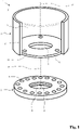
- the valve protection device 1 shown comprises two sections 2, 3 that can be connected to one another, namely a fastening section 2 for fastening to a compressed gas cylinder and a valve protection section 3 that can be connected to the fastening section 2.
- the attachment section 2 in the form of an annular disk in the exemplary embodiment has a central bore 4 with an internal thread 5 for screwing onto the neck thread of a compressed gas bottle.
- the size of the central bore 4 is determined by the neck thread and is, for example, 80 ⁇ 2.309 (Whitworth) in conventional compressed gas cylinders.
- the valve protection section 3 has a bottom side 6 which is equipped with a central bore 7 .
- the diameter of the central bore 7 is designed such that a cylinder valve (not shown here) can be passed through the bore 7 .
- the diameter of the central bore is therefore larger than the diameter of the central bore 4.
- the valve protection section 3 is connected to the fastening section 2 in the manner described in more detail below.
- a plurality of bores 10 are arranged in the fastening section 2 at equal angular spacings and the same radial spacing from the central axis 8 .
- bores 11 are arranged in the bottom side 6 of the valve protection section 3 at a radial distance from the bore 7, the radial distance of the bores 11 from the central axis 12 of the central bore 7 being the same as the radial distance of the bores 10 from the central axis 8.
- provided in the bottom side 6 three holes, but it can also be more or less.
- the number of bores 10 in the fastening section 2 can be the same as or different from the number of bores in the bottom side 6 . It is necessary that the angular distances of the bores 11 are dimensioned in such a way that when the two sections 2, 3 are connected to one another - described in more detail below - several bores 10 are present, which are aligned with one another with the bores 11 at a suitable angular position of the two sections 2, 3.
- the valve protection section 3 includes a protective structure 14 for protecting a cylinder valve, not shown here, and any additional installations connected to the cylinder valve (likewise not shown here), such as pressure reducers, line connections or display instruments.
- the protective structure 14 has at least one access opening 15 through which the cylinder valve and/or the aforesaid internals are made accessible to an operator.
- the protective structure 14 is a hollow cylinder reduced by the cut-out access opening 15 and made of an impact-resistant material, in particular metal or plastic, which is firmly connected to the bottom side 6, for example by welding.
- the configurations of the protective structure and access opening that are possible according to the invention are not limited to this, but rather depend on the requirements with regard to the type, size and arrangement of the built-in components and the required protection.
- the fastening section 2 is first screwed onto the neck valve of the gas cylinder.
- a cylinder valve such as a VIPR, is then screwed tightly into the neck of the gas cylinder.
- the bottom side 6 of the valve protection section 3 is then placed on the fastening section 2, the mounted cylinder valve being guided through the central bore 7 and the axes 8, 12 being brought into line.
- the angular position of the two sections 2 , 3 relative to one another is chosen such that the bores 11 in the bottom side 6 are aligned with the bores 10 or a corresponding number of bores 10 in the fastening section 2 .
- the sections are then connected to one another at the aligned bores 10, 11 by means of suitable connecting means, for example with a threaded rod (not shown here), which is guided through the two aligned bores 10, 11 and then fixed by means of nuts screwed onto both end faces.
- suitable connecting means for example with a threaded rod (not shown here), which is guided through the two aligned bores 10, 11 and then fixed by means of nuts screwed onto both end faces.
- the bores 10 or the bores 11 can be equipped with threads and the fastening takes place by means of Screws that pass through the bore 10, 11 of one section 2, 3 and are screwed into the threaded bore 11, 10 of the other section 3, 2.
- the angular position of the two sections 2, 3 relative to one another i.e. the angular position in a plane perpendicular to the axes 8, 10 can be selected according to the number of bores 10.
- An angular position is expediently selected which allows good accessibility of the cylinder valve and, if applicable, other built-in components connected to it through the access opening 15 .
- valve protection device 1′ shown only partially, with a fastening section 2′ and a valve protection section 3′ with an alternative possibility of connecting the sections 2′, 3′ to one another.
- the sections 2', 3' are similar to the sections 2, 3 from the exemplary embodiment according to FIG 1 constructed, ie the attachment portion 2' has a central bore with an internal thread for screwing onto the neck thread of a compressed gas cylinder, and the valve protection portion 3' has a bottom side 6' and a protective structure 14'.
- a plurality of latching grooves 18 are provided on the fastening section 2', which are arranged at equal angular intervals in the outer casing 19 of the fastening section 2'.
- a plurality of latching hooks 21 are arranged on the outer casing 20 of the bottom side 6', for example formed in one piece with the bottom side 6' or welded, glued or screwed to it.
- the latching hooks 21 are made of a material with limited flexibility, for example plastic, and their shape and size correspond to the latching grooves 19.
Landscapes
- Engineering & Computer Science (AREA)
- Mechanical Engineering (AREA)
- General Engineering & Computer Science (AREA)
- Filling Or Discharging Of Gas Storage Vessels (AREA)
- Supply Devices, Intensifiers, Converters, And Telemotors (AREA)
Claims (8)
- Dispositif de protection de valve pour bouteilles de gaz comprimé, comportant une partie de fixation (2, 2') qui est équipée de moyens (5) servant à la fixation à un filetage de col d'une bouteille de gaz comprimé et comprend un alésage central (4), et comportant une partie de protection de valve (3, 3') pouvant être reliée à la partie de fixation (2, 2'), laquelle partie de protection de valve comprend un côté de fond (6, 6') doté d'un alésage central (7) pour le passage d'une valve de bouteille et une structure de protection (14, 14') reliée fixement au côté de fond (6, 6') et dotée d'au moins une ouverture d'accès (15) pour la manipulation de la valve de bouteille, les alésages centraux (4, 7) de la partie de fixation (2, 2') et du côté de fond (6, 6') étant disposés en formant un axe médian commun (8, 12) après la liaison des deux parties (2, 2' ; 3, 3'),la partie de fixation (2, 2') et la partie de protection de valve (3, 3') étant équipées de moyens de liaison (10, 18 ; 11, 21) correspondant les uns aux autres, lesquels sont réalisés de telle sorte qu'une liaison fixe axialement peut être produite entre respectivement un moyen de liaison (10, 18 ; 11, 21) de l'une des parties (2, 2' ; 3, 3') et un moyen de liaison (10, 18 ; 11, 21) de l'autre partie (2, 2' ; 3, 3'), au moins les moyens de liaison (10, 18 ; 11, 21) d'une partie (2, 2' ; 3, 3') étant disposés suivant une symétrie de révolution par rapport à une rotation autour de l'axe médian (8, 12) et, en cas de rotation des deux parties (2, 2' ; 3, 3') l'une par rapport à l'autre autour de l'axe médian (8, 12), au moins deux positions angulaires existant, dans lesquelles plusieurs moyens de liaison (10, 18 ; 11, 21) de l'une des parties (2, 2' ; 3, 3') peuvent être reliés à des moyens de liaison (10, 18 ; 11, 21) de l'autre partie (2, 2' ; 3, 3'), 2' ; 3, 3'),caractérisé en ce quela partie de fixation (2, 2') et la partie de protection de valve (3, 3') sont équipées respectivement d'une pluralité d'alésages (10, 11) disposés de manière équidistante radialement de l'axe médian, les alésages (10, 11) d'au moins une partie (2, 2' ; 3, 3') étant disposés à des distances angulaires uniformes et correspondant aux alésages (10, 11) de l'autre partie, de telle sorte qu'en cas de rotation autour de l'axe médian (8, 12) les uns par rapport aux autres, au moins dans deux positions angulaires, une pluralité d'alésages (11, 11) de l'une des parties (2, 2' ; 3, 3') sont alignés avec une pluralité d'alésages (10, 11) de l'autre partie (2, 2' ; 3, 3') et peuvent être reliés fixement par complémentarité de formes à l'aide de moyens de fixation.
- Dispositif de protection de valve selon la revendication 1, caractérisé en ce que le nombre de moyens de liaison (10, 18 ; 11, 21) de l'une des parties (2, 2' ; 3, 3') est supérieur au nombre de moyens de liaison (10, 18 ; 11, 21) de l'autre partie (2, 2' ; 3, 3').
- Dispositif de protection de valve selon la revendication 1, caractérisé en ce que les alésages (10, 11) d'une partie (2, 2' ; 3, 3') sont équipés de filetages intérieurs.
- Dispositif de protection de valve pour bouteilles de gaz comprimé, comportant une partie de fixation (2, 2') qui est équipée de moyens (5) servant à la fixation à un filetage de col d'une bouteille de gaz comprimé et comprend un alésage central (4), et comportant une partie de protection de valve (3, 3') pouvant être reliée à la partie de fixation (2, 2'), laquelle partie de protection de valve comprend un côté de fond (6, 6') doté d'un alésage central (7) pour le passage d'une valve de bouteille et une structure de protection (14, 14') reliée fixement au côté de fond (6, 6') et dotée d'au moins une ouverture d'accès (15) pour la manipulation de la valve de bouteille, les alésages centraux (4, 7) de la partie de fixation (2, 2') et du côté de fond (6, 6') étant disposés en formant un axe médian commun (8, 12) après la liaison des deux parties (2, 2' ; 3, 3'),la partie de fixation (2, 2') et la partie de protection de valve (3, 3') étant équipées de moyens de liaison (10, 18 ; 11, 21) correspondant les uns aux autres, lesquels sont réalisés de telle sorte qu'une liaison fixe axialement peut être produite entre respectivement un moyen de liaison (10, 18 ; 11, 21) de l'une des parties (2, 2' ; 3, 3') et un moyen de liaison (10, 18 ; 11, 21) de l'autre partie (2, 2' ; 3, 3'), au moins les moyens de liaison (10, 18 ; 11, 21) d'une partie (2, 2' ; 3, 3') étant disposés suivant une symétrie de révolution par rapport à une rotation autour de l'axe médian (8, 12) et, en cas de rotation des deux parties (2, 2' ; 3, 3') l'une par rapport à l'autre autour de l'axe médian (8, 12), au moins deux positions angulaires existant, dans lesquelles plusieurs moyens de liaison (10, 18 ; 11, 21) de l'une des parties (2, 2' ; 3, 3') peuvent être reliés à des moyens de liaison (10, 18 ; 11, 21) de l'autre partie (2, 2' ; 3, 3'),caractérisé en ce quela partie de fixation (2, 2') ou la partie de protection de valve (3, 3') est équipée d'une pluralité de rainures d'encliquetage (18) qui sont disposées respectivement de manière équidistante d'un axe médian (8, 12) du dispositif de protection de valve (1, 1') et sont disposées à des distances angulaires uniformes radialement par rapport à l'axe médian (8, 12) et correspondent à des crochets d'encliquetage (21) de l'autre partie (2, 2' ; 3, 3') de telle sorte qu'en cas de rotation autour de l'axe médian (8, 12) des deux parties (2, 2' ; 3, 3') l'une par rapport à l'autre, au moins dans deux positions angulaires, une pluralité de rainures d'encliquetage (18) coopèrent avec une pluralité de crochets d'encliquetage (21) pour produire une liaison fixe axialement.
- Dispositif de protection de valve selon l'une des revendications précédentes, caractérisé en ce que la partie de fixation (2, 2') ou la partie de protection de valve (3, 3') est équipée d'une pluralité de boulons faisant saillie à partir de celle-ci parallèlement à l'axe médian (8, 12) et à une même distance radiale et à des distances angulaires uniformes, lesquels boulons correspondent à des alésages (10, 11) disposés de manière correspondante dans l'autre partie (2, 2', 3, 3') respective, de telle sorte qu'en cas de rotation autour de l'axe médian (8, 12) des deux parties (2, 2' ; 3, 3') l'une par rapport à l'autre, au moins dans deux positions angulaires, les boulons peuvent être guidés à travers une pluralité d'alésages (10, 11), les boulons pouvant être protégés axialement contre un glissement hors des alésages (10, 11) à l'aide d'éléments de sécurité.
- Dispositif de protection de valve selon l'une des revendications précédentes, caractérisé en ce qu'un auxiliaire de positionnement est prévu pour la fixation axiale des deux parties (2, 2' ; 3, 3') l'une par rapport à l'autre.
- Dispositif de protection de valve selon l'une des revendications précédentes, caractérisé en ce que la partie de fixation (2, 2') et/ou la partie de protection de valve (3, 3') est/sont fabriqué(e)s au moins partiellement à partir de métal.
- Dispositif de protection de valve selon l'une des revendications précédentes, caractérisé en ce que la partie de fixation (2, 2') et/ou la partie de protection de valve (3, 3') est/sont fabriqué(e)s au moins partiellement à partir de matière synthétique.
Applications Claiming Priority (1)
| Application Number | Priority Date | Filing Date | Title |
|---|---|---|---|
| DE102017007162.4A DE102017007162A1 (de) | 2017-07-27 | 2017-07-27 | Ventilschutzeinrichtung für Druckgasbehälter |
Publications (2)
| Publication Number | Publication Date |
|---|---|
| EP3434963A1 EP3434963A1 (fr) | 2019-01-30 |
| EP3434963B1 true EP3434963B1 (fr) | 2022-05-04 |
Family
ID=62778693
Family Applications (1)
| Application Number | Title | Priority Date | Filing Date |
|---|---|---|---|
| EP18178283.0A Active EP3434963B1 (fr) | 2017-07-27 | 2018-06-18 | Dispositif de protection de soupape pour réservoir de gaz comprimé |
Country Status (4)
| Country | Link |
|---|---|
| EP (1) | EP3434963B1 (fr) |
| DE (1) | DE102017007162A1 (fr) |
| ES (1) | ES2919952T3 (fr) |
| PL (1) | PL3434963T3 (fr) |
Families Citing this family (5)
| Publication number | Priority date | Publication date | Assignee | Title |
|---|---|---|---|---|
| US10982814B2 (en) | 2019-09-03 | 2021-04-20 | Amtrol Licensing Inc. | Handle assembly for a portable pressurized gas cylinder |
| USD930783S1 (en) | 2019-09-03 | 2021-09-14 | Amtrol Licensing, Inc. | Handle |
| US11585491B2 (en) * | 2020-08-06 | 2023-02-21 | Amtrol Licensing Inc. | Handle for a portable cylinder |
| US12129970B2 (en) | 2023-02-17 | 2024-10-29 | Amtrol Licensing Inc. | Handle for a portable cylinder |
| USD1124227S1 (en) | 2023-02-17 | 2026-04-28 | Amtrol Licensing Inc. | Handle |
Family Cites Families (4)
| Publication number | Priority date | Publication date | Assignee | Title |
|---|---|---|---|---|
| US5709252A (en) * | 1995-06-06 | 1998-01-20 | Progas, Inc. | Natural gas distribution system |
| FR3013101B1 (fr) * | 2013-11-08 | 2015-11-06 | Rovip | Protecteur universel pour bouteille a gaz |
| GB2509229A (en) | 2013-11-19 | 2014-06-25 | Rolls Royce Plc | Gas turbine engine fan stand with hinged rotating frame |
| EP3193072B1 (fr) * | 2016-01-12 | 2017-12-13 | Rovip | Protecteur universel pour bouteille de gaz |
-
2017
- 2017-07-27 DE DE102017007162.4A patent/DE102017007162A1/de not_active Withdrawn
-
2018
- 2018-06-18 PL PL18178283.0T patent/PL3434963T3/pl unknown
- 2018-06-18 EP EP18178283.0A patent/EP3434963B1/fr active Active
- 2018-06-18 ES ES18178283T patent/ES2919952T3/es active Active
Also Published As
| Publication number | Publication date |
|---|---|
| PL3434963T3 (pl) | 2022-08-08 |
| DE102017007162A1 (de) | 2019-01-31 |
| ES2919952T3 (es) | 2022-07-29 |
| EP3434963A1 (fr) | 2019-01-30 |
Similar Documents
| Publication | Publication Date | Title |
|---|---|---|
| EP3434963B1 (fr) | Dispositif de protection de soupape pour réservoir de gaz comprimé | |
| DE69902944T2 (de) | Befestigungsvorrichtung zum schnellen an- bzw. abkoppeln eines bauteils an eine bzw. von einer auflagefläche | |
| EP3032093B1 (fr) | Dispositif de fixation d'une pale de rotor sur un moyeu de rotor d'une éolienne | |
| DE60219774T2 (de) | Ventilsperrvorrichtung | |
| DE10056341C2 (de) | Vorrichtung zum Verzurren von Containern | |
| DE4200096A1 (de) | Vorrichtung zum verschliessen einer oeffnung in einer verkleidung | |
| DE202020103617U1 (de) | Verdrehsicherung | |
| DE2615322C2 (de) | Befestigungsvorrichtung für Türschilder bzw. Türrosetten | |
| DE102015007288B4 (de) | Zollverschluss | |
| DE4225743C2 (de) | Schutzkappe aus Kunststoff | |
| EP0729540B1 (fr) | Paumelle de porte ou de fenetre | |
| EP2530223B1 (fr) | Clôture de sécurité | |
| DE10050024C2 (de) | Ventilanordnung | |
| EP3574813B1 (fr) | Charnière pour un ensemble d'un siège de toilettes | |
| DE2945540A1 (de) | Abschliessbarer verschluss fuer oeltankfuellrohre | |
| DE102004049886B4 (de) | Einrichtung zum Verbinden eines Anbauteils mit einem Blechträger, insbesondere einem Längsträger eines Kraftfahrzeugs | |
| DE2248724A1 (de) | Tuerband | |
| EP4256210B1 (fr) | Rondelle de recouvrement de fentes | |
| DE19962595A1 (de) | Werkstück mit einem drehbaren Innengewinde sowie Blindnietmutter für ein solches Werkstück | |
| EP0387634A1 (fr) | Armature avec limiteur de course | |
| DE102018122701A1 (de) | Haltersystem zur Befestigung eines Behälters an einem Fahrzeug | |
| EP0861955B1 (fr) | Bouton de fenêtre verrouiable | |
| DE9306014U1 (de) | Autokühlerfigur | |
| DE8527958U1 (de) | Türbeschlag | |
| DE19703880C2 (de) | Verriegelungsvorrichtung |
Legal Events
| Date | Code | Title | Description |
|---|---|---|---|
| PUAI | Public reference made under article 153(3) epc to a published international application that has entered the european phase |
Free format text: ORIGINAL CODE: 0009012 |
|
| STAA | Information on the status of an ep patent application or granted ep patent |
Free format text: STATUS: THE APPLICATION HAS BEEN PUBLISHED |
|
| AK | Designated contracting states |
Kind code of ref document: A1 Designated state(s): AL AT BE BG CH CY CZ DE DK EE ES FI FR GB GR HR HU IE IS IT LI LT LU LV MC MK MT NL NO PL PT RO RS SE SI SK SM TR |
|
| AX | Request for extension of the european patent |
Extension state: BA ME |
|
| STAA | Information on the status of an ep patent application or granted ep patent |
Free format text: STATUS: REQUEST FOR EXAMINATION WAS MADE |
|
| 17P | Request for examination filed |
Effective date: 20190730 |
|
| RAX | Requested extension states of the european patent have changed |
Extension state: BA Payment date: 20190730 Extension state: ME Payment date: 20190730 |
|
| RBV | Designated contracting states (corrected) |
Designated state(s): AL AT BE BG CH CY CZ DE DK EE ES FI FR GB GR HR HU IE IS IT LI LT LU LV MC MK MT NL NO PL PT RO RS SE SI SK SM TR |
|
| GRAP | Despatch of communication of intention to grant a patent |
Free format text: ORIGINAL CODE: EPIDOSNIGR1 |
|
| STAA | Information on the status of an ep patent application or granted ep patent |
Free format text: STATUS: GRANT OF PATENT IS INTENDED |
|
| INTG | Intention to grant announced |
Effective date: 20211202 |
|
| GRAS | Grant fee paid |
Free format text: ORIGINAL CODE: EPIDOSNIGR3 |
|
| GRAA | (expected) grant |
Free format text: ORIGINAL CODE: 0009210 |
|
| STAA | Information on the status of an ep patent application or granted ep patent |
Free format text: STATUS: THE PATENT HAS BEEN GRANTED |
|
| AK | Designated contracting states |
Kind code of ref document: B1 Designated state(s): AL AT BE BG CH CY CZ DE DK EE ES FI FR GB GR HR HU IE IS IT LI LT LU LV MC MK MT NL NO PL PT RO RS SE SI SK SM TR |
|
| REG | Reference to a national code |
Ref country code: GB Ref legal event code: FG4D Free format text: NOT ENGLISH |
|
| REG | Reference to a national code |
Ref country code: CH Ref legal event code: EP |
|
| REG | Reference to a national code |
Ref country code: AT Ref legal event code: REF Ref document number: 1489400 Country of ref document: AT Kind code of ref document: T Effective date: 20220515 |
|
| REG | Reference to a national code |
Ref country code: DE Ref legal event code: R096 Ref document number: 502018009542 Country of ref document: DE |
|
| REG | Reference to a national code |
Ref country code: IE Ref legal event code: FG4D Free format text: LANGUAGE OF EP DOCUMENT: GERMAN |
|
| REG | Reference to a national code |
Ref country code: ES Ref legal event code: FG2A Ref document number: 2919952 Country of ref document: ES Kind code of ref document: T3 Effective date: 20220729 |
|
| REG | Reference to a national code |
Ref country code: LT Ref legal event code: MG9D |
|
| REG | Reference to a national code |
Ref country code: NL Ref legal event code: MP Effective date: 20220504 |
|
| PG25 | Lapsed in a contracting state [announced via postgrant information from national office to epo] |
Ref country code: SE Free format text: LAPSE BECAUSE OF FAILURE TO SUBMIT A TRANSLATION OF THE DESCRIPTION OR TO PAY THE FEE WITHIN THE PRESCRIBED TIME-LIMIT Effective date: 20220504 Ref country code: PT Free format text: LAPSE BECAUSE OF FAILURE TO SUBMIT A TRANSLATION OF THE DESCRIPTION OR TO PAY THE FEE WITHIN THE PRESCRIBED TIME-LIMIT Effective date: 20220905 Ref country code: NO Free format text: LAPSE BECAUSE OF FAILURE TO SUBMIT A TRANSLATION OF THE DESCRIPTION OR TO PAY THE FEE WITHIN THE PRESCRIBED TIME-LIMIT Effective date: 20220804 Ref country code: NL Free format text: LAPSE BECAUSE OF FAILURE TO SUBMIT A TRANSLATION OF THE DESCRIPTION OR TO PAY THE FEE WITHIN THE PRESCRIBED TIME-LIMIT Effective date: 20220504 Ref country code: LT Free format text: LAPSE BECAUSE OF FAILURE TO SUBMIT A TRANSLATION OF THE DESCRIPTION OR TO PAY THE FEE WITHIN THE PRESCRIBED TIME-LIMIT Effective date: 20220504 Ref country code: HR Free format text: LAPSE BECAUSE OF FAILURE TO SUBMIT A TRANSLATION OF THE DESCRIPTION OR TO PAY THE FEE WITHIN THE PRESCRIBED TIME-LIMIT Effective date: 20220504 Ref country code: GR Free format text: LAPSE BECAUSE OF FAILURE TO SUBMIT A TRANSLATION OF THE DESCRIPTION OR TO PAY THE FEE WITHIN THE PRESCRIBED TIME-LIMIT Effective date: 20220805 Ref country code: FI Free format text: LAPSE BECAUSE OF FAILURE TO SUBMIT A TRANSLATION OF THE DESCRIPTION OR TO PAY THE FEE WITHIN THE PRESCRIBED TIME-LIMIT Effective date: 20220504 Ref country code: BG Free format text: LAPSE BECAUSE OF FAILURE TO SUBMIT A TRANSLATION OF THE DESCRIPTION OR TO PAY THE FEE WITHIN THE PRESCRIBED TIME-LIMIT Effective date: 20220804 |
|
| PG25 | Lapsed in a contracting state [announced via postgrant information from national office to epo] |
Ref country code: RS Free format text: LAPSE BECAUSE OF FAILURE TO SUBMIT A TRANSLATION OF THE DESCRIPTION OR TO PAY THE FEE WITHIN THE PRESCRIBED TIME-LIMIT Effective date: 20220504 Ref country code: LV Free format text: LAPSE BECAUSE OF FAILURE TO SUBMIT A TRANSLATION OF THE DESCRIPTION OR TO PAY THE FEE WITHIN THE PRESCRIBED TIME-LIMIT Effective date: 20220504 Ref country code: IS Free format text: LAPSE BECAUSE OF FAILURE TO SUBMIT A TRANSLATION OF THE DESCRIPTION OR TO PAY THE FEE WITHIN THE PRESCRIBED TIME-LIMIT Effective date: 20220904 |
|
| PG25 | Lapsed in a contracting state [announced via postgrant information from national office to epo] |
Ref country code: SM Free format text: LAPSE BECAUSE OF FAILURE TO SUBMIT A TRANSLATION OF THE DESCRIPTION OR TO PAY THE FEE WITHIN THE PRESCRIBED TIME-LIMIT Effective date: 20220504 Ref country code: SK Free format text: LAPSE BECAUSE OF FAILURE TO SUBMIT A TRANSLATION OF THE DESCRIPTION OR TO PAY THE FEE WITHIN THE PRESCRIBED TIME-LIMIT Effective date: 20220504 Ref country code: RO Free format text: LAPSE BECAUSE OF FAILURE TO SUBMIT A TRANSLATION OF THE DESCRIPTION OR TO PAY THE FEE WITHIN THE PRESCRIBED TIME-LIMIT Effective date: 20220504 Ref country code: EE Free format text: LAPSE BECAUSE OF FAILURE TO SUBMIT A TRANSLATION OF THE DESCRIPTION OR TO PAY THE FEE WITHIN THE PRESCRIBED TIME-LIMIT Effective date: 20220504 Ref country code: DK Free format text: LAPSE BECAUSE OF FAILURE TO SUBMIT A TRANSLATION OF THE DESCRIPTION OR TO PAY THE FEE WITHIN THE PRESCRIBED TIME-LIMIT Effective date: 20220504 Ref country code: CZ Free format text: LAPSE BECAUSE OF FAILURE TO SUBMIT A TRANSLATION OF THE DESCRIPTION OR TO PAY THE FEE WITHIN THE PRESCRIBED TIME-LIMIT Effective date: 20220504 |
|
| REG | Reference to a national code |
Ref country code: CH Ref legal event code: PL |
|
| REG | Reference to a national code |
Ref country code: DE Ref legal event code: R097 Ref document number: 502018009542 Country of ref document: DE |
|
| REG | Reference to a national code |
Ref country code: BE Ref legal event code: MM Effective date: 20220630 |
|
| PG25 | Lapsed in a contracting state [announced via postgrant information from national office to epo] |
Ref country code: MC Free format text: LAPSE BECAUSE OF FAILURE TO SUBMIT A TRANSLATION OF THE DESCRIPTION OR TO PAY THE FEE WITHIN THE PRESCRIBED TIME-LIMIT Effective date: 20220504 |
|
| PLBE | No opposition filed within time limit |
Free format text: ORIGINAL CODE: 0009261 |
|
| STAA | Information on the status of an ep patent application or granted ep patent |
Free format text: STATUS: NO OPPOSITION FILED WITHIN TIME LIMIT |
|
| PG25 | Lapsed in a contracting state [announced via postgrant information from national office to epo] |
Ref country code: AL Free format text: LAPSE BECAUSE OF FAILURE TO SUBMIT A TRANSLATION OF THE DESCRIPTION OR TO PAY THE FEE WITHIN THE PRESCRIBED TIME-LIMIT Effective date: 20220504 |
|
| 26N | No opposition filed |
Effective date: 20230207 |
|
| GBPC | Gb: european patent ceased through non-payment of renewal fee |
Effective date: 20220804 |
|
| PG25 | Lapsed in a contracting state [announced via postgrant information from national office to epo] |
Ref country code: LU Free format text: LAPSE BECAUSE OF NON-PAYMENT OF DUE FEES Effective date: 20220618 Ref country code: LI Free format text: LAPSE BECAUSE OF NON-PAYMENT OF DUE FEES Effective date: 20220630 Ref country code: IE Free format text: LAPSE BECAUSE OF NON-PAYMENT OF DUE FEES Effective date: 20220618 Ref country code: CH Free format text: LAPSE BECAUSE OF NON-PAYMENT OF DUE FEES Effective date: 20220630 |
|
| PG25 | Lapsed in a contracting state [announced via postgrant information from national office to epo] |
Ref country code: SI Free format text: LAPSE BECAUSE OF FAILURE TO SUBMIT A TRANSLATION OF THE DESCRIPTION OR TO PAY THE FEE WITHIN THE PRESCRIBED TIME-LIMIT Effective date: 20220504 Ref country code: BE Free format text: LAPSE BECAUSE OF NON-PAYMENT OF DUE FEES Effective date: 20220630 |
|
| PG25 | Lapsed in a contracting state [announced via postgrant information from national office to epo] |
Ref country code: GB Free format text: LAPSE BECAUSE OF NON-PAYMENT OF DUE FEES Effective date: 20220804 |
|
| PG25 | Lapsed in a contracting state [announced via postgrant information from national office to epo] |
Ref country code: IT Free format text: LAPSE BECAUSE OF FAILURE TO SUBMIT A TRANSLATION OF THE DESCRIPTION OR TO PAY THE FEE WITHIN THE PRESCRIBED TIME-LIMIT Effective date: 20220504 |
|
| PG25 | Lapsed in a contracting state [announced via postgrant information from national office to epo] |
Ref country code: HU Free format text: LAPSE BECAUSE OF FAILURE TO SUBMIT A TRANSLATION OF THE DESCRIPTION OR TO PAY THE FEE WITHIN THE PRESCRIBED TIME-LIMIT; INVALID AB INITIO Effective date: 20180618 |
|
| PG25 | Lapsed in a contracting state [announced via postgrant information from national office to epo] |
Ref country code: MK Free format text: LAPSE BECAUSE OF FAILURE TO SUBMIT A TRANSLATION OF THE DESCRIPTION OR TO PAY THE FEE WITHIN THE PRESCRIBED TIME-LIMIT Effective date: 20220504 Ref country code: CY Free format text: LAPSE BECAUSE OF FAILURE TO SUBMIT A TRANSLATION OF THE DESCRIPTION OR TO PAY THE FEE WITHIN THE PRESCRIBED TIME-LIMIT Effective date: 20220504 |
|
| REG | Reference to a national code |
Ref country code: AT Ref legal event code: MM01 Ref document number: 1489400 Country of ref document: AT Kind code of ref document: T Effective date: 20230618 |
|
| PG25 | Lapsed in a contracting state [announced via postgrant information from national office to epo] |
Ref country code: MT Free format text: LAPSE BECAUSE OF FAILURE TO SUBMIT A TRANSLATION OF THE DESCRIPTION OR TO PAY THE FEE WITHIN THE PRESCRIBED TIME-LIMIT Effective date: 20220504 |
|
| PG25 | Lapsed in a contracting state [announced via postgrant information from national office to epo] |
Ref country code: AT Free format text: LAPSE BECAUSE OF NON-PAYMENT OF DUE FEES Effective date: 20230618 |
|
| PG25 | Lapsed in a contracting state [announced via postgrant information from national office to epo] |
Ref country code: AT Free format text: LAPSE BECAUSE OF NON-PAYMENT OF DUE FEES Effective date: 20230618 |
|
| PG25 | Lapsed in a contracting state [announced via postgrant information from national office to epo] |
Ref country code: BG Free format text: LAPSE BECAUSE OF FAILURE TO SUBMIT A TRANSLATION OF THE DESCRIPTION OR TO PAY THE FEE WITHIN THE PRESCRIBED TIME-LIMIT Effective date: 20220504 |
|
| PG25 | Lapsed in a contracting state [announced via postgrant information from national office to epo] |
Ref country code: BG Free format text: LAPSE BECAUSE OF FAILURE TO SUBMIT A TRANSLATION OF THE DESCRIPTION OR TO PAY THE FEE WITHIN THE PRESCRIBED TIME-LIMIT Effective date: 20220504 |
|
| PGFP | Annual fee paid to national office [announced via postgrant information from national office to epo] |
Ref country code: DE Payment date: 20250630 Year of fee payment: 8 |
|
| PGFP | Annual fee paid to national office [announced via postgrant information from national office to epo] |
Ref country code: FR Payment date: 20250409 Year of fee payment: 8 |
|
| PGFP | Annual fee paid to national office [announced via postgrant information from national office to epo] |
Ref country code: ES Payment date: 20250707 Year of fee payment: 8 |
|
| PG25 | Lapsed in a contracting state [announced via postgrant information from national office to epo] |
Ref country code: TR Free format text: LAPSE BECAUSE OF FAILURE TO SUBMIT A TRANSLATION OF THE DESCRIPTION OR TO PAY THE FEE WITHIN THE PRESCRIBED TIME-LIMIT Effective date: 20220504 |
|
| PGFP | Annual fee paid to national office [announced via postgrant information from national office to epo] |
Ref country code: AT Payment date: 20260410 Year of fee payment: 5 |
|
| PGFP | Annual fee paid to national office [announced via postgrant information from national office to epo] |
Ref country code: PL Payment date: 20260327 Year of fee payment: 9 |