EP3434975A2 - Brennkammer für verschiedenartige fester brennstoffe - Google Patents
Brennkammer für verschiedenartige fester brennstoffe Download PDFInfo
- Publication number
- EP3434975A2 EP3434975A2 EP17770501.9A EP17770501A EP3434975A2 EP 3434975 A2 EP3434975 A2 EP 3434975A2 EP 17770501 A EP17770501 A EP 17770501A EP 3434975 A2 EP3434975 A2 EP 3434975A2
- Authority
- EP
- European Patent Office
- Prior art keywords
- combustion
- combustion chamber
- primary
- primary combustion
- fuel
- Prior art date
- Legal status (The legal status is an assumption and is not a legal conclusion. Google has not performed a legal analysis and makes no representation as to the accuracy of the status listed.)
- Withdrawn
Links
Images




Classifications
-
- F—MECHANICAL ENGINEERING; LIGHTING; HEATING; WEAPONS; BLASTING
- F23—COMBUSTION APPARATUS; COMBUSTION PROCESSES
- F23B—METHODS OR APPARATUS FOR COMBUSTION USING ONLY SOLID FUEL
- F23B10/00—Combustion apparatus characterised by the combination of two or more combustion chambers
- F23B10/02—Combustion apparatus characterised by the combination of two or more combustion chambers including separate secondary combustion chambers
-
- F—MECHANICAL ENGINEERING; LIGHTING; HEATING; WEAPONS; BLASTING
- F23—COMBUSTION APPARATUS; COMBUSTION PROCESSES
- F23B—METHODS OR APPARATUS FOR COMBUSTION USING ONLY SOLID FUEL
- F23B5/00—Combustion apparatus with arrangements for burning uncombusted material from primary combustion
- F23B5/02—Combustion apparatus with arrangements for burning uncombusted material from primary combustion in main combustion chamber
-
- F—MECHANICAL ENGINEERING; LIGHTING; HEATING; WEAPONS; BLASTING
- F23—COMBUSTION APPARATUS; COMBUSTION PROCESSES
- F23B—METHODS OR APPARATUS FOR COMBUSTION USING ONLY SOLID FUEL
- F23B30/00—Combustion apparatus with driven means for agitating the burning fuel; Combustion apparatus with driven means for advancing the burning fuel through the combustion chamber
-
- F—MECHANICAL ENGINEERING; LIGHTING; HEATING; WEAPONS; BLASTING
- F23—COMBUSTION APPARATUS; COMBUSTION PROCESSES
- F23B—METHODS OR APPARATUS FOR COMBUSTION USING ONLY SOLID FUEL
- F23B7/00—Combustion techniques; Other solid-fuel combustion apparatus
- F23B7/002—Combustion techniques; Other solid-fuel combustion apparatus characterised by gas flow arrangements
-
- F—MECHANICAL ENGINEERING; LIGHTING; HEATING; WEAPONS; BLASTING
- F23—COMBUSTION APPARATUS; COMBUSTION PROCESSES
- F23B—METHODS OR APPARATUS FOR COMBUSTION USING ONLY SOLID FUEL
- F23B80/00—Combustion apparatus characterised by means creating a distinct flow path for flue gases or for non-combusted gases given off by the fuel
- F23B80/02—Combustion apparatus characterised by means creating a distinct flow path for flue gases or for non-combusted gases given off by the fuel by means for returning flue gases to the combustion chamber or to the combustion zone
-
- F—MECHANICAL ENGINEERING; LIGHTING; HEATING; WEAPONS; BLASTING
- F23—COMBUSTION APPARATUS; COMBUSTION PROCESSES
- F23B—METHODS OR APPARATUS FOR COMBUSTION USING ONLY SOLID FUEL
- F23B80/00—Combustion apparatus characterised by means creating a distinct flow path for flue gases or for non-combusted gases given off by the fuel
- F23B80/04—Combustion apparatus characterised by means creating a distinct flow path for flue gases or for non-combusted gases given off by the fuel by means for guiding the flow of flue gases, e.g. baffles
-
- F—MECHANICAL ENGINEERING; LIGHTING; HEATING; WEAPONS; BLASTING
- F23—COMBUSTION APPARATUS; COMBUSTION PROCESSES
- F23B—METHODS OR APPARATUS FOR COMBUSTION USING ONLY SOLID FUEL
- F23B90/00—Combustion methods not related to a particular type of apparatus
- F23B90/04—Combustion methods not related to a particular type of apparatus including secondary combustion
- F23B90/06—Combustion methods not related to a particular type of apparatus including secondary combustion the primary combustion being a gasification or pyrolysis in a reductive atmosphere
-
- F—MECHANICAL ENGINEERING; LIGHTING; HEATING; WEAPONS; BLASTING
- F23—COMBUSTION APPARATUS; COMBUSTION PROCESSES
- F23L—SUPPLYING AIR OR NON-COMBUSTIBLE LIQUIDS OR GASES TO COMBUSTION APPARATUS IN GENERAL ; VALVES OR DAMPERS SPECIALLY ADAPTED FOR CONTROLLING AIR SUPPLY OR DRAUGHT IN COMBUSTION APPARATUS; INDUCING DRAUGHT IN COMBUSTION APPARATUS; TOPS FOR CHIMNEYS OR VENTILATING SHAFTS; TERMINALS FOR FLUES
- F23L1/00—Passages or apertures for delivering primary air for combustion
-
- F—MECHANICAL ENGINEERING; LIGHTING; HEATING; WEAPONS; BLASTING
- F23—COMBUSTION APPARATUS; COMBUSTION PROCESSES
- F23L—SUPPLYING AIR OR NON-COMBUSTIBLE LIQUIDS OR GASES TO COMBUSTION APPARATUS IN GENERAL ; VALVES OR DAMPERS SPECIALLY ADAPTED FOR CONTROLLING AIR SUPPLY OR DRAUGHT IN COMBUSTION APPARATUS; INDUCING DRAUGHT IN COMBUSTION APPARATUS; TOPS FOR CHIMNEYS OR VENTILATING SHAFTS; TERMINALS FOR FLUES
- F23L15/00—Heating of air supplied for combustion
-
- F—MECHANICAL ENGINEERING; LIGHTING; HEATING; WEAPONS; BLASTING
- F23—COMBUSTION APPARATUS; COMBUSTION PROCESSES
- F23L—SUPPLYING AIR OR NON-COMBUSTIBLE LIQUIDS OR GASES TO COMBUSTION APPARATUS IN GENERAL ; VALVES OR DAMPERS SPECIALLY ADAPTED FOR CONTROLLING AIR SUPPLY OR DRAUGHT IN COMBUSTION APPARATUS; INDUCING DRAUGHT IN COMBUSTION APPARATUS; TOPS FOR CHIMNEYS OR VENTILATING SHAFTS; TERMINALS FOR FLUES
- F23L5/00—Blast-producing apparatus before the fire
- F23L5/02—Arrangements of fans or blowers
-
- F—MECHANICAL ENGINEERING; LIGHTING; HEATING; WEAPONS; BLASTING
- F23—COMBUSTION APPARATUS; COMBUSTION PROCESSES
- F23L—SUPPLYING AIR OR NON-COMBUSTIBLE LIQUIDS OR GASES TO COMBUSTION APPARATUS IN GENERAL ; VALVES OR DAMPERS SPECIALLY ADAPTED FOR CONTROLLING AIR SUPPLY OR DRAUGHT IN COMBUSTION APPARATUS; INDUCING DRAUGHT IN COMBUSTION APPARATUS; TOPS FOR CHIMNEYS OR VENTILATING SHAFTS; TERMINALS FOR FLUES
- F23L9/00—Passages or apertures for delivering secondary air for completing combustion of fuel
- F23L9/02—Passages or apertures for delivering secondary air for completing combustion of fuel by discharging the air above the fire
-
- F—MECHANICAL ENGINEERING; LIGHTING; HEATING; WEAPONS; BLASTING
- F23—COMBUSTION APPARATUS; COMBUSTION PROCESSES
- F23L—SUPPLYING AIR OR NON-COMBUSTIBLE LIQUIDS OR GASES TO COMBUSTION APPARATUS IN GENERAL ; VALVES OR DAMPERS SPECIALLY ADAPTED FOR CONTROLLING AIR SUPPLY OR DRAUGHT IN COMBUSTION APPARATUS; INDUCING DRAUGHT IN COMBUSTION APPARATUS; TOPS FOR CHIMNEYS OR VENTILATING SHAFTS; TERMINALS FOR FLUES
- F23L9/00—Passages or apertures for delivering secondary air for completing combustion of fuel
- F23L9/04—Passages or apertures for delivering secondary air for completing combustion of fuel by discharging the air beyond the fire, i.e. nearer the smoke outlet
-
- F—MECHANICAL ENGINEERING; LIGHTING; HEATING; WEAPONS; BLASTING
- F24—HEATING; RANGES; VENTILATING
- F24B—DOMESTIC STOVES OR RANGES FOR SOLID FUELS; IMPLEMENTS FOR USE IN CONNECTION WITH STOVES OR RANGES
- F24B1/00—Stoves or ranges
- F24B1/02—Closed stoves
- F24B1/026—Closed stoves with several combustion zones
-
- F—MECHANICAL ENGINEERING; LIGHTING; HEATING; WEAPONS; BLASTING
- F24—HEATING; RANGES; VENTILATING
- F24B—DOMESTIC STOVES OR RANGES FOR SOLID FUELS; IMPLEMENTS FOR USE IN CONNECTION WITH STOVES OR RANGES
- F24B1/00—Stoves or ranges
- F24B1/02—Closed stoves
- F24B1/08—Closed stoves with fuel storage in a single undivided hopper within stove or range
-
- F—MECHANICAL ENGINEERING; LIGHTING; HEATING; WEAPONS; BLASTING
- F24—HEATING; RANGES; VENTILATING
- F24B—DOMESTIC STOVES OR RANGES FOR SOLID FUELS; IMPLEMENTS FOR USE IN CONNECTION WITH STOVES OR RANGES
- F24B13/00—Details solely applicable to stoves or ranges burning solid fuels
- F24B13/04—Arrangements for feeding solid fuel, e.g. hoppers
-
- F—MECHANICAL ENGINEERING; LIGHTING; HEATING; WEAPONS; BLASTING
- F24—HEATING; RANGES; VENTILATING
- F24B—DOMESTIC STOVES OR RANGES FOR SOLID FUELS; IMPLEMENTS FOR USE IN CONNECTION WITH STOVES OR RANGES
- F24B5/00—Combustion-air or flue-gas circulation in or around stoves or ranges
- F24B5/02—Combustion-air or flue-gas circulation in or around stoves or ranges in or around stoves
- F24B5/021—Combustion-air or flue-gas circulation in or around stoves or ranges in or around stoves combustion-air circulation
- F24B5/026—Supply of primary and secondary air for combustion
-
- F—MECHANICAL ENGINEERING; LIGHTING; HEATING; WEAPONS; BLASTING
- F24—HEATING; RANGES; VENTILATING
- F24B—DOMESTIC STOVES OR RANGES FOR SOLID FUELS; IMPLEMENTS FOR USE IN CONNECTION WITH STOVES OR RANGES
- F24B5/00—Combustion-air or flue-gas circulation in or around stoves or ranges
- F24B5/02—Combustion-air or flue-gas circulation in or around stoves or ranges in or around stoves
- F24B5/028—Arrangements combining combustion-air and flue-gas circulation
-
- F—MECHANICAL ENGINEERING; LIGHTING; HEATING; WEAPONS; BLASTING
- F24—HEATING; RANGES; VENTILATING
- F24B—DOMESTIC STOVES OR RANGES FOR SOLID FUELS; IMPLEMENTS FOR USE IN CONNECTION WITH STOVES OR RANGES
- F24B5/00—Combustion-air or flue-gas circulation in or around stoves or ranges
- F24B5/02—Combustion-air or flue-gas circulation in or around stoves or ranges in or around stoves
- F24B5/04—Combustion-air or flue-gas circulation in or around stoves or ranges in or around stoves the air or gas passing downwards through the bottom of the stove of fire grate
-
- F—MECHANICAL ENGINEERING; LIGHTING; HEATING; WEAPONS; BLASTING
- F23—COMBUSTION APPARATUS; COMBUSTION PROCESSES
- F23B—METHODS OR APPARATUS FOR COMBUSTION USING ONLY SOLID FUEL
- F23B2700/00—Combustion apparatus for solid fuel
- F23B2700/018—Combustion apparatus for solid fuel with fume afterburning by staged combustion
-
- Y—GENERAL TAGGING OF NEW TECHNOLOGICAL DEVELOPMENTS; GENERAL TAGGING OF CROSS-SECTIONAL TECHNOLOGIES SPANNING OVER SEVERAL SECTIONS OF THE IPC; TECHNICAL SUBJECTS COVERED BY FORMER USPC CROSS-REFERENCE ART COLLECTIONS [XRACs] AND DIGESTS
- Y02—TECHNOLOGIES OR APPLICATIONS FOR MITIGATION OR ADAPTATION AGAINST CLIMATE CHANGE
- Y02E—REDUCTION OF GREENHOUSE GAS [GHG] EMISSIONS, RELATED TO ENERGY GENERATION, TRANSMISSION OR DISTRIBUTION
- Y02E20/00—Combustion technologies with mitigation potential
- Y02E20/34—Indirect CO2mitigation, i.e. by acting on non CO2directly related matters of the process, e.g. pre-heating or heat recovery
Definitions
- the present invention relates to a combustion device capable of combusting biomass fuel including firewood, woodchips, pellets, agricultural by-products and other various solid fuels regardless of kinds thereof by increasing a combustion efficiency through a method of thermally decomposing a solid fuel by returning directly heat generated by secondary combustion of the solid fuel to the fuel.
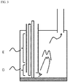
- FIG. 1 is a view for analyzing combustion of firewood, that is, a bonfire, under a condition in which a sufficient amount of air is supplied.
- a region A is a region in which wood gas generated and fumed by thermally decomposing firewood comes into contact with air and is primarily combusted. Some primary combustion heat thereof is an important factor in continuously combusting by returning to the wood and being used as an energy source which thermally decomposes the wood. The remaining primary combustion heat is radiated in all directions.
- a region B is an expansion and combustion region in which an oxidation reaction occurs between wood gas which is not combusted and air in order to generate heat and light and increase a temperature of a combustion gas.
- a large amount of thermal energy generated in this region is emitted to a space by radiation and convection, and only a small amount of energy returns to the wood and is used for thermal decomposition.
- a region C is an end portion of a combustion flame in which a temperature is highest among the regions of the bonfire flame. Energy generated in the region C mostly does not return to the wood.
- each or both of a fireproof heat accumulating material 13 and a fireproof insulating material are stacked around a vicinity of firewood in which primary combustion occurs, heat generated by the primary combustion is accumulated and reflected to return to the wood fuel to facilitate thermal decomposition of the wood fuel and stably maintains a wood combustion reaction with a small amount of primary air 11 without supplying excessive air.
- an efficiency and stability of the combustion is achieved by preheating and supplying air through a suitable heat exchanger 15 using the combustion heat of the regions B and C.
- combustion gas directly returns to a vicinity of a firewood feed pipe and directly acts to heat supplied air and the firewood feed pipe.
- the primary combustion is performed at a lower side of the firewood feed pipe, that is a region D, and a combustion flame rises to perform the secondary expansion and combustion, and thus when a vicinity of the firewood feed pipe of a region E is heated, supply air supplied through the pipe is heated and energy is supplied to firewood in contact with the pipe by thermal conduction and radiation.
- a method is not provided in which thermal decomposition of a fuel of a primary combustion region is effectively promoted by switching a combustion gas path to return heat generated by the secondary combustion by conduction and radiation.
- the present invention is directed to providing a combustor operated under a stable combustion condition by switching a combustion gas path to return and supply secondary combustion heat to a fuel by conducting and radiating the fuel so as to stably thermally decompose the fuel.
- the present invention is directed to performing combustion with one combustor regardless of kinds, forms, and sizes of moisture-content fuels by normally maintaining gasification combustion through thermal decomposition of a fuel.
- the present invention is directed to preventing excessive NO x generation simultaneously while preventing smoke generation corresponding to incomplete combustion because gasification combustion due to thermal decomposition of a fuel is maintained and thus necessary supply air is maintained at a suitable level.
- One aspect of the present invention provides a combustor for various types of solid fuels including: a fuel supply device having a firewood feed pipe or another fuel supplier; a primary combustion chamber coupled to the fuel supply device, wherein a combustion gas outlet formed in one side surface or at a lower side of the primary combustion chamber and the remaining surfaces thereof are blocked by a wall formed of a fireproof material so that primary combustion is performed; a secondary combustion chamber including a wall formed of a fireproof material and having a structure in which a space is formed at a side of the combustion gas outlet of the primary combustion chamber to induce primary combustion gas to be secondarily expanded and combusted, a flow direction of secondary combustion gas is switched after the expansion and combustion to form a path such that the secondary combustion gas comes into contact with and flows along at least one of a lower external wall and a side surface wall of the primary combustion chamber and intensively transfers secondary combustion heat to a fuel in a combustion region of the primary combustion chamber by conduction and radiation; and an air supply system including at least one air supply device in an entire combustion
- the firewood feed pipe may be disposed at an upper portion of the primary combustion chamber and formed in a column shape of which a cross section is a circle, oval, or polygon shape, and a preheating air supply device configured to cool the firewood feed pipe may be added above the primary combustion chamber to increase an efficiency thereof.
- the primary combustion chamber wall may be basically formed of a thermally conductive fireproof material, and when a material having a low thermal conductivity is applied to a large combustor having high heat output, an efficiency thereof may increase.
- the secondary combustion chamber wall may be basically formed of a fireproof insulating material, but a large combustor having high heat output may be formed of a thermally conductive material to improve an efficiency and stability thereof.
- the air supply system may distribute supply air to several positions including an inside of the primary combustion chamber, a start position of the secondary expansion and combustion chamber, and an end position of the secondary combustion chamber so that an output of the combustion device may be adjusted by primary and secondary supply air to reduce NO x generation and perform complete combustion.
- Temperatures in the primary and secondary combustion chambers and exhausted gas detected by an oxygen sensor may be analyzed to electronically control an amount of supply air in order to improve preciseness of air adjustment.
- a combustion grid may be disposed in the primary combustion chamber so that the combustion grid may be replaceable by a combustion grid corresponding to a fuel characteristic such that various kinds of fuels are allowed to be combusted.
- a solid combustor according to the present invention has an effect in that an amount of NO x generation and smoke generation due to incomplete combustion is reduced because a stable combustion condition can be provided regardless of a kind, a quality, and the form of a fuel and air supply can be optimized by transferring generated heat to a combustion region in which primary combustion is performed after secondary combustion through a primary combustion chamber wall by conduction radiation, and has an advantage in that a large amount of heat can be output even when a size of the combustor is small.
- the present invention may be naturally applied to a boiler by additionally installing a water container therewith, a hot blast heater by attaching a heat exchanger thereto, and the like.
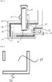
- a firewood feed pipe 29 for supplying a fuel has a column shape of which a cross section is a circle, oval, or polygon shape, various fuels such as firewood, woodchips, and pellets are fundamentally stacked in the firewood feed pipe 29, and the firewood feed pipe 29 serves to continuously supply the fuel to a primary combustion region 27.
- an external preheating air supply device 21 is provided around the firewood feed pipe above a combustion chamber, there are effects in that a combustion duration time and combustion stability are improved by preheating air supplied to the combustion chamber to improve a combustion efficiency thereof and simultaneously absorbing and cooling heat coming from the combustion chamber to prevent thermal decomposition of a fuel in a non-combustion region.
- a secondary air supply device 23 configured to supply air to a secondary expansion and combustion chamber and a third air supply device 22 configured to supply air after secondary expansion and combustion are included in the combustor.
- a heat outlet is formed in one side surface of the primary combustion region 27 formed at a lower end of the fuel supply pipe and another surface 26 in which the heat outlet is not formed is formed of a thermally conductive fireproof material, and when a primary combustion gas is secondarily expanded and combusted, the primary combustion gas comes into direct contact with an outer surface of a primary combustion chamber wall and is turned and flows. Secondary combustion heat is transferred by conduction and radiation through the primary combustion chamber wall 26 and used to thermally decompose a fuel in the primary combustion chamber to maintain continuous gasification combustion.
- combustion supply air is classified into primary air directly supplied to the primary combustion chamber, secondary air supplied to the secondary expansion and combustion chamber 28, and third air sprayed after the secondary combustion is performed and the secondary air is turned and flows along the primary combustion chamber. In this case, the following effects may occur.
- the primary air is directly supplied to a fuel to generate heat so as to increase a temperature in the combustion chamber.
- an amount of the secondary and third air is minimized to increase the temperature in the combustion chamber.
- the temperature in the combustion chamber increases, when an amount of primary air is decreased and an amount of the secondary air is increased, combustion stability is improved, and when a fuel is fully thermally decomposed by secondary combustion heat, the amount of primary air is reduced to a suitable level, the amount of secondary air is increased to decrease an absolute amount of supply air necessary for combustion, and a size of a combustion flame region is increased to adjust an amount of NO x generation.
- the third air additionally supplies oxygen to a portion incompletely combusted by only the primary and secondary air to completely combust the portion.
- an output of combustion is adjusted by an amount of the primary air and the secondary air, and the third air serves as auxiliary supply air for complete combustion.
- the primary air is directly sprayed on a fuel to directly adjust the output
- the secondary air combusts incompletely combusted gas after the primary combustion to generate secondary combustion heat and promote thermal decomposition of the fuel (generating gas) through the primary combustion chamber wall 26, the secondary air directly participates to adjust the heat output.
- the third air combusts incompletely combusted gas after the primary and secondary combustion and discharges generated heat to a rear heat radiation portion, the third air is not related to the adjustment of the output of the combustion.
- the classification of the supply air into the primary, the secondary, and the third air provides a method in which an amount of NO x generation due to a high temperature in a small region and supply of excessive amount of air (oxygen) is dramatically reduced because an absolute amount of supply air decreases, and combustion heat disperses over a wide region.
- a device configured to adjust an amount of supply air is not illustrated in the drawings because of being a known technology, and the secondary and third air may be supplied through the preheating air supply device 21 and may also be supplied through a separated line. Even when the secondary and third air are supplied through the separated line, since the secondary and third air is supplied through a preheated section inside the combustor, combustion stability is maintained.
- the secondary expansion and combustion chamber since a temperature in the secondary expansion and combustion chamber becomes highest and the secondary expansion and combustion chamber serves to switch a heat path in an opposite direction, the secondary expansion and combustion chamber has to be formed of a fireproof material which may withstand high temperatures well, and a material of the secondary combustion chamber wall 24 has to be different from materials of the other components which have different thermal conductivities from that of the material of the secondary combustion chamber wall 24 according to a total size of the combustor.
- a material of a partition wall since the combustor for camping installed in a small tent has a small output and a high temperature is difficult to maintain in the combustion chamber, a material of a partition wall has to be a material capable of maximizing a thermal insulation effect to maintain combustion quality.
- the combustor for a large workplace is formed such that the secondary combustion chamber wall 24 is formed of a thermally conductive material to prevent a temperature in the primary combustion chamber from becoming ultra-high such that secondary combustion gas in which a temperature is lowered through some degree of radiation turns and flows along the primary combustion chamber wall to reduce NO x generated due to the ultra-high temperature and also protect the primary combustion wall.
- a reprocessing device 25 for reprocessing may be formed at a lower portion of the secondary expansion and combustion chamber, and one housing 20 may externally surround an entirety of both the primary and secondary combustion chambers to develop a stove structure configured to directly radiate heat, a boiler structure in which a water container is disposed, a hot blast heater in which an air and heat exchanger is disposed, or the like.
- FIG. 5 is a view illustrating the primary combustion chamber wall having a structure of a middle air layer.
- the primary combustion chamber wall is basically formed of a thermally conductive material, since excessive secondary combustion heat transferred to the primary combustion chamber causes excessive thermal decomposition in the large combustor of which a thermal output is high, the primary combustion wall having a structure of a middle air layer in which a thermal conductivity is reduced may be suitable for combustion stability.
- the large combustor may include the primary combustion wall formed of one of various materials including a fireproof brick and the like.
- FIG. 6 is a schematic view illustrating the above-described combustor when the firewood feed pipe has a circular structure.
- secondary combustion gas turns and flows along bottom and both side surfaces of the primary combustion chamber toward a rear heat outlet, the path is formed along a lower side of the primary combustion chamber when the both side surfaces of the heat path are formed to be extremely narrow, and the path is formed along the both side surfaces when the path along the bottom surface is highly reduced.
- the primary combustion chamber may also be variously formed such that one side surface of the both side surfaces is formed to be wide and the other side surface thereof is formed to be narrow.
- the firewood feed pipe may be similarly applied as a polygonal structure including a tetragonal firewood feed pipe, and a separate drawing thereof is omitted because of being cleared to those skilled in the art.
- FIG. 7 is a view illustrating a combustor in which an outlet of primary combustion gas is positioned at a lower side of the combustor, and combustion gas is transferred to a primary combustion chamber mainly along both side surfaces of the primary combustion chamber after secondary expansion and combustion.
- FIG. 8 is a schematic view illustrating a combustor in which a reprocessing grid is additionally disposed under a primary combustion chamber to increase combustion stability by rapidly reprocessing a fuel from which a large amount of reprocessing fuel is generated during combustion.
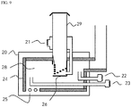
- FIG. 9 is a view illustrating a combustor in which a combustion grid disposed in a primary combustion chamber and configured to effectively combust a fuel such as pellets or woodchips is disposed to be replaceable by a kind of combustion grid corresponding to a fuel characteristic.
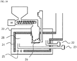
- FIG. 10 is a view illustrating a combustor in which an automated fuel supply system including a transferring screw and a fuel storage hopper is installed instead of a firewood feed pipe.
- the combustor can operate for a long time period without an additional operation using the automated fuel supply system.
- an oxygen sensor may be added to a side of an outlet of a secondary combustion chamber to more precisely adjust an amount of supply air.
- an amount of air may be adjusted by installing one or more temperature sensors in a primary combustion chamber, a secondary combustion chamber, and a radiation portion and providing an electronic control circuit such that a combustor is operated under conditions of a highly suitable temperature and a most suitable amount of oxygen with information from the oxygen sensor.
- the above-described solid fuel combustor can be variously technically applied to devices from an air heating device such as a firewood stove and a pellet stove, to a water heating device such as a firewood boiler and a pellet boiler, a stove and a boiler configured to combust agricultural by-products, and a burner for a small pollution-free home electricity generator.
Landscapes
- Engineering & Computer Science (AREA)
- Chemical & Material Sciences (AREA)
- Combustion & Propulsion (AREA)
- Mechanical Engineering (AREA)
- General Engineering & Computer Science (AREA)
- Physics & Mathematics (AREA)
- Thermal Sciences (AREA)
- Solid-Fuel Combustion (AREA)
Applications Claiming Priority (2)
| Application Number | Priority Date | Filing Date | Title |
|---|---|---|---|
| KR1020160033097A KR101825285B1 (ko) | 2016-03-21 | 2016-03-21 | 다종 고체연료 연소기 |
| PCT/KR2017/002196 WO2017164530A2 (ko) | 2016-03-21 | 2017-02-28 | 다종 고체연료 연소기 |
Publications (2)
| Publication Number | Publication Date |
|---|---|
| EP3434975A2 true EP3434975A2 (de) | 2019-01-30 |
| EP3434975A4 EP3434975A4 (de) | 2019-11-20 |
Family
ID=59900607
Family Applications (1)
| Application Number | Title | Priority Date | Filing Date |
|---|---|---|---|
| EP17770501.9A Withdrawn EP3434975A4 (de) | 2016-03-21 | 2017-02-28 | Brennkammer für verschiedenartige fester brennstoffe |
Country Status (5)
| Country | Link |
|---|---|
| US (1) | US10890321B2 (de) |
| EP (1) | EP3434975A4 (de) |
| KR (1) | KR101825285B1 (de) |
| CN (1) | CN108700286A (de) |
| WO (1) | WO2017164530A2 (de) |
Families Citing this family (3)
| Publication number | Priority date | Publication date | Assignee | Title |
|---|---|---|---|---|
| CN109708149A (zh) * | 2019-01-21 | 2019-05-03 | 山东正信德环保科技发展有限公司 | 多重燃烧采暖炉 |
| CN110425573B (zh) * | 2019-08-27 | 2024-03-01 | 中国矿业大学 | 一种清洁安全型燃烧系统及方法 |
| US11767980B2 (en) * | 2020-11-03 | 2023-09-26 | Dansons Us, Llc | Longitudinal burn pot assembly and improved air flow system |
Family Cites Families (21)
| Publication number | Priority date | Publication date | Assignee | Title |
|---|---|---|---|---|
| US4779607A (en) * | 1987-02-03 | 1988-10-25 | Nu-Tec Incorporated | Stove |
| US4836115A (en) * | 1988-06-23 | 1989-06-06 | Macarthur Charles E | Vertical furnace |
| JP2598752B2 (ja) * | 1994-02-10 | 1997-04-09 | 新日本技研株式会社 | 焼却炉 |
| CN100356103C (zh) * | 2002-06-03 | 2007-12-19 | 霍努阿技术公司 | 医疗废弃物和其它废料的热解方法 |
| JP2005207727A (ja) | 2003-12-22 | 2005-08-04 | Keiichi Kotaka | 木炭燃焼装置 |
| CN201069245Y (zh) * | 2006-12-28 | 2008-06-04 | 付文宏 | 秸秆、原煤、型煤三用锅炉 |
| ITUD20080014A1 (it) | 2008-01-24 | 2009-07-25 | Palazzetti Lelio Spa | Bruciatore verticale per un'apparecchiatura per il riscaldamento domestico |
| US20100089295A1 (en) * | 2008-10-15 | 2010-04-15 | Mel Moench | Continuously-Fed Non-Densified Biomass Combustion System |
| JP5480814B2 (ja) * | 2008-10-20 | 2014-04-23 | 株式会社ガイア環境技術研究所 | 炭化処理装置及び炭化処理方法 |
| DE102009007458B4 (de) * | 2009-02-04 | 2013-08-29 | Karl Stefan Riener | Scheitholzofen |
| CN201582798U (zh) * | 2009-12-31 | 2010-09-15 | 河南省科学院能源研究所有限公司 | 生物质成型燃料燃烧设备 |
| CN201697135U (zh) * | 2010-05-11 | 2011-01-05 | 吴学良 | 一种新型垃圾与生物质燃料焚烧炉 |
| US20120312205A1 (en) * | 2011-06-13 | 2012-12-13 | Meeker John G | Woodkiln molded combustion chamber |
| KR20130004708U (ko) | 2012-01-26 | 2013-08-05 | 송윤영 | 화력 조절 장치를 갖춘 포켓 스토브 |
| US20140311477A1 (en) * | 2013-03-07 | 2014-10-23 | Reginald James Davenport | Control system for monitoring and adjusting combustion performance in a cordwood-fired heating appliance |
| KR101462333B1 (ko) | 2013-03-19 | 2014-11-20 | 송기택 | 화목 난로 |
| KR101391400B1 (ko) | 2013-04-01 | 2014-05-02 | 장정훈 | 하향 연소식 화목 보일러 |
| EP2821698A1 (de) * | 2013-05-01 | 2015-01-07 | Aristidis Afentoulidis | In einer Primärbrennkammer eines Vergaserkessels für feste Biomasse angeordnete rohrförmige Sekundärbrennkammer |
| KR101515001B1 (ko) * | 2014-03-31 | 2015-05-04 | 임재욱 | 펠렛난로 |
| KR101471636B1 (ko) | 2014-08-29 | 2014-12-15 | 한국기계연구원 | 저공해 펠릿 연소 장치 및 그 방법 |
| DE102015004823A1 (de) * | 2015-04-14 | 2016-11-03 | Rika Innovative Ofentechnik Gmbh | Ofen |
-
2016
- 2016-03-21 KR KR1020160033097A patent/KR101825285B1/ko active Active
-
2017
- 2017-02-28 EP EP17770501.9A patent/EP3434975A4/de not_active Withdrawn
- 2017-02-28 US US16/082,276 patent/US10890321B2/en active Active
- 2017-02-28 WO PCT/KR2017/002196 patent/WO2017164530A2/ko not_active Ceased
- 2017-02-28 CN CN201780011857.5A patent/CN108700286A/zh active Pending
Also Published As
| Publication number | Publication date |
|---|---|
| US10890321B2 (en) | 2021-01-12 |
| CN108700286A (zh) | 2018-10-23 |
| US20190078775A1 (en) | 2019-03-14 |
| EP3434975A4 (de) | 2019-11-20 |
| WO2017164530A3 (ko) | 2018-08-02 |
| KR101825285B1 (ko) | 2018-02-02 |
| WO2017164530A2 (ko) | 2017-09-28 |
| KR20170109251A (ko) | 2017-09-29 |
Similar Documents
| Publication | Publication Date | Title |
|---|---|---|
| JP5410567B2 (ja) | 燃焼装置 | |
| US10890321B2 (en) | Combustor for various types of solid fuels | |
| US20190249870A1 (en) | Pyrolysis Boiler | |
| JP6109484B2 (ja) | 燃料電池装置 | |
| KR101413183B1 (ko) | 폐가스 소각장치 및 소각방법 | |
| JP2007178057A (ja) | バイオマス燃料給湯器 | |
| CN212127506U (zh) | 天然气重整装置和sofc发电系统 | |
| US20160238258A1 (en) | Combustion apparatus | |
| CN104315504A (zh) | 一种可抑制燃烧高温区形成的循环流化床锅炉及抑制方法 | |
| KR101774057B1 (ko) | 물의 전기분해와 열분해가 결합된 열병합 발전시스템 및 발전방법 | |
| EP2940399B1 (de) | Kesselsystem mit brennstoffzelle | |
| KR20150125288A (ko) | 펠릿 겸용 수평식 화목 가스화 보일러 | |
| KR101090378B1 (ko) | 연소 효율이 우수한 보일러 | |
| RU2471128C1 (ru) | Водогрейный твердотопливный котел | |
| KR101944031B1 (ko) | 복사열을 이용한 연소 장치 및 방법 | |
| RU184378U9 (ru) | Пиролизный котел | |
| CN212081223U (zh) | 醇基燃料储热式催化燃烧内胆及其所构成的低氮热源装置 | |
| KR20120076703A (ko) | 폐기물 고형연료를 이용한 보일러의 연소장치 | |
| JP3119032U (ja) | ペレットストーブ | |
| KR101775015B1 (ko) | 숯가마를 이용한 연소장치 | |
| Pleshanov et al. | Combustion of bark and wood waste in the fluidized bed boiler | |
| KR20140043773A (ko) | 과립고체 연료버너 및 그것을 이용한 보일러 | |
| JP2016031204A (ja) | 粉体燃焼用バーナ | |
| Wójcik | EVOLUTION OF SOLID AND GAS FUEL REACTORS IN THE MUNICIPAL ECONOMY. | |
| RU2596682C2 (ru) | Вертикальная топка пароводогрейного котла для преобразования сыпучих видов топлива в тепловую энергию с камерами дожига пиролизных газов |
Legal Events
| Date | Code | Title | Description |
|---|---|---|---|
| STAA | Information on the status of an ep patent application or granted ep patent |
Free format text: STATUS: THE INTERNATIONAL PUBLICATION HAS BEEN MADE |
|
| PUAI | Public reference made under article 153(3) epc to a published international application that has entered the european phase |
Free format text: ORIGINAL CODE: 0009012 |
|
| STAA | Information on the status of an ep patent application or granted ep patent |
Free format text: STATUS: REQUEST FOR EXAMINATION WAS MADE |
|
| 17P | Request for examination filed |
Effective date: 20181022 |
|
| AK | Designated contracting states |
Kind code of ref document: A2 Designated state(s): AL AT BE BG CH CY CZ DE DK EE ES FI FR GB GR HR HU IE IS IT LI LT LU LV MC MK MT NL NO PL PT RO RS SE SI SK SM TR |
|
| AX | Request for extension of the european patent |
Extension state: BA ME |
|
| DAV | Request for validation of the european patent (deleted) | ||
| DAX | Request for extension of the european patent (deleted) | ||
| A4 | Supplementary search report drawn up and despatched |
Effective date: 20191022 |
|
| RIC1 | Information provided on ipc code assigned before grant |
Ipc: F24B 5/02 20060101ALI20191016BHEP Ipc: F23B 30/00 20060101AFI20191016BHEP Ipc: F23L 5/02 20060101ALI20191016BHEP Ipc: F24B 1/02 20060101ALI20191016BHEP Ipc: F23B 10/02 20110101ALI20191016BHEP Ipc: F24B 5/04 20060101ALI20191016BHEP Ipc: F23L 9/02 20060101ALI20191016BHEP Ipc: F23B 80/02 20060101ALI20191016BHEP Ipc: F23L 9/04 20060101ALI20191016BHEP Ipc: F23B 90/06 20110101ALI20191016BHEP Ipc: F23L 15/00 20060101ALI20191016BHEP Ipc: F23B 80/04 20060101ALI20191016BHEP Ipc: F23L 1/00 20060101ALI20191016BHEP |
|
| STAA | Information on the status of an ep patent application or granted ep patent |
Free format text: STATUS: THE APPLICATION IS DEEMED TO BE WITHDRAWN |
|
| 18D | Application deemed to be withdrawn |
Effective date: 20200603 |