EP3435032A1 - Capteur optique de rugosité pour une machine de mesure de coordonnées - Google Patents
Capteur optique de rugosité pour une machine de mesure de coordonnées Download PDFInfo
- Publication number
- EP3435032A1 EP3435032A1 EP17183279.3A EP17183279A EP3435032A1 EP 3435032 A1 EP3435032 A1 EP 3435032A1 EP 17183279 A EP17183279 A EP 17183279A EP 3435032 A1 EP3435032 A1 EP 3435032A1
- Authority
- EP
- European Patent Office
- Prior art keywords
- sensor
- signal
- roughness
- roughness sensor
- optical
- Prior art date
- Legal status (The legal status is an assumption and is not a legal conclusion. Google has not performed a legal analysis and makes no representation as to the accuracy of the status listed.)
- Granted
Links
Images


Classifications
-
- G—PHYSICS
- G01—MEASURING; TESTING
- G01B—MEASURING LENGTH, THICKNESS OR SIMILAR LINEAR DIMENSIONS; MEASURING ANGLES; MEASURING AREAS; MEASURING IRREGULARITIES OF SURFACES OR CONTOURS
- G01B11/00—Measuring arrangements characterised by the use of optical techniques
- G01B11/30—Measuring arrangements characterised by the use of optical techniques for measuring roughness or irregularity of surfaces
- G01B11/303—Measuring arrangements characterised by the use of optical techniques for measuring roughness or irregularity of surfaces using photoelectric detection means
-
- G—PHYSICS
- G01—MEASURING; TESTING
- G01B—MEASURING LENGTH, THICKNESS OR SIMILAR LINEAR DIMENSIONS; MEASURING ANGLES; MEASURING AREAS; MEASURING IRREGULARITIES OF SURFACES OR CONTOURS
- G01B11/00—Measuring arrangements characterised by the use of optical techniques
- G01B11/30—Measuring arrangements characterised by the use of optical techniques for measuring roughness or irregularity of surfaces
-
- G—PHYSICS
- G01—MEASURING; TESTING
- G01B—MEASURING LENGTH, THICKNESS OR SIMILAR LINEAR DIMENSIONS; MEASURING ANGLES; MEASURING AREAS; MEASURING IRREGULARITIES OF SURFACES OR CONTOURS
- G01B11/00—Measuring arrangements characterised by the use of optical techniques
- G01B11/002—Measuring arrangements characterised by the use of optical techniques for measuring two or more coordinates
- G01B11/005—Measuring arrangements characterised by the use of optical techniques for measuring two or more coordinates coordinate measuring machines
-
- G—PHYSICS
- G01—MEASURING; TESTING
- G01B—MEASURING LENGTH, THICKNESS OR SIMILAR LINEAR DIMENSIONS; MEASURING ANGLES; MEASURING AREAS; MEASURING IRREGULARITIES OF SURFACES OR CONTOURS
- G01B11/00—Measuring arrangements characterised by the use of optical techniques
- G01B11/002—Measuring arrangements characterised by the use of optical techniques for measuring two or more coordinates
- G01B11/005—Measuring arrangements characterised by the use of optical techniques for measuring two or more coordinates coordinate measuring machines
- G01B11/007—Measuring arrangements characterised by the use of optical techniques for measuring two or more coordinates coordinate measuring machines feeler heads therefor
-
- G—PHYSICS
- G01—MEASURING; TESTING
- G01B—MEASURING LENGTH, THICKNESS OR SIMILAR LINEAR DIMENSIONS; MEASURING ANGLES; MEASURING AREAS; MEASURING IRREGULARITIES OF SURFACES OR CONTOURS
- G01B11/00—Measuring arrangements characterised by the use of optical techniques
- G01B11/24—Measuring arrangements characterised by the use of optical techniques for measuring contours or curvatures
- G01B11/2441—Measuring arrangements characterised by the use of optical techniques for measuring contours or curvatures using interferometry
-
- G—PHYSICS
- G01—MEASURING; TESTING
- G01B—MEASURING LENGTH, THICKNESS OR SIMILAR LINEAR DIMENSIONS; MEASURING ANGLES; MEASURING AREAS; MEASURING IRREGULARITIES OF SURFACES OR CONTOURS
- G01B5/00—Measuring arrangements characterised by the use of mechanical techniques
- G01B5/004—Measuring arrangements characterised by the use of mechanical techniques for measuring coordinates of points
- G01B5/008—Measuring arrangements characterised by the use of mechanical techniques for measuring coordinates of points using coordinate measuring machines
-
- G—PHYSICS
- G01—MEASURING; TESTING
- G01B—MEASURING LENGTH, THICKNESS OR SIMILAR LINEAR DIMENSIONS; MEASURING ANGLES; MEASURING AREAS; MEASURING IRREGULARITIES OF SURFACES OR CONTOURS
- G01B9/00—Measuring instruments characterised by the use of optical techniques
- G01B9/02—Interferometers
- G01B9/02001—Interferometers characterised by controlling or generating intrinsic radiation properties
- G01B9/02002—Interferometers characterised by controlling or generating intrinsic radiation properties using two or more frequencies
- G01B9/02004—Interferometers characterised by controlling or generating intrinsic radiation properties using two or more frequencies using frequency scans
-
- G—PHYSICS
- G01—MEASURING; TESTING
- G01B—MEASURING LENGTH, THICKNESS OR SIMILAR LINEAR DIMENSIONS; MEASURING ANGLES; MEASURING AREAS; MEASURING IRREGULARITIES OF SURFACES OR CONTOURS
- G01B21/00—Measuring arrangements or details thereof, where the measuring technique is not covered by the other groups of this subclass, unspecified or not relevant
- G01B21/02—Measuring arrangements or details thereof, where the measuring technique is not covered by the other groups of this subclass, unspecified or not relevant for measuring length, width, or thickness
- G01B21/04—Measuring arrangements or details thereof, where the measuring technique is not covered by the other groups of this subclass, unspecified or not relevant for measuring length, width, or thickness by measuring coordinates of points
-
- G—PHYSICS
- G01—MEASURING; TESTING
- G01B—MEASURING LENGTH, THICKNESS OR SIMILAR LINEAR DIMENSIONS; MEASURING ANGLES; MEASURING AREAS; MEASURING IRREGULARITIES OF SURFACES OR CONTOURS
- G01B9/00—Measuring instruments characterised by the use of optical techniques
- G01B9/02—Interferometers
- G01B9/02001—Interferometers characterised by controlling or generating intrinsic radiation properties
- G01B9/02007—Two or more frequencies or sources used for interferometric measurement
-
- G—PHYSICS
- G01—MEASURING; TESTING
- G01B—MEASURING LENGTH, THICKNESS OR SIMILAR LINEAR DIMENSIONS; MEASURING ANGLES; MEASURING AREAS; MEASURING IRREGULARITIES OF SURFACES OR CONTOURS
- G01B9/00—Measuring instruments characterised by the use of optical techniques
- G01B9/02—Interferometers
- G01B9/02055—Reduction or prevention of errors; Testing; Calibration
-
- G—PHYSICS
- G01—MEASURING; TESTING
- G01B—MEASURING LENGTH, THICKNESS OR SIMILAR LINEAR DIMENSIONS; MEASURING ANGLES; MEASURING AREAS; MEASURING IRREGULARITIES OF SURFACES OR CONTOURS
- G01B9/00—Measuring instruments characterised by the use of optical techniques
- G01B9/02—Interferometers
- G01B9/0209—Low-coherence interferometers
- G01B9/02091—Tomographic interferometers, e.g. based on optical coherence
Definitions
- the invention relates to an optical roughness sensor for detecting surface information and to a coordinate measuring machine (CMM) for roughness measurement of an object surface by means of such a sensor.
- CCM coordinate measuring machine
- Coordinate measuring machines are usually used for these applications, which allow a precise measurement of the geometry of an object surface, typically with micrometer accuracy.
- Objects to be measured may be engine blocks, gears and tools, for example.
- Known coordinate measuring machines measure the surface by making a mechanical contact and scanning the surface. Examples of this are portal measuring machines, such as those in the DE 43 25 337 or DE 43 25 347 to be discribed.
- Another system is based on the use of an articulated arm, whose measuring sensor arranged at the end of the multi-part arm can be moved along the surface. Generic articulated arms are used for example in the US 5,402,582 or the EP 1 474 650 described.
- the sensor is designed with a measuring tip of known geometry, typically spherical or ellipsoidal for specific applications, typically with a (main) radius of the order of a few millimeters.
- the term "measuring tip” is to be understood in the context of the present invention generally as a (tactile) measuring sensor of any shape and dimension, which does not necessarily have to have a tapered shape (but can).
- the raw data measured with the coordinate measuring machine using a tactile sensor represent the measured location coordinates of a reference point of the measuring tip, for example the measuring tip center.
- the measurement resolution is limited.
- the physical dimension of the measuring tip or the associated limited measurement resolution lead to a "smoothing effect" when measuring rough surfaces: While surveys or tips of an object surface measured almost perfectly or objectively can be, the probe tip of the tactile sensor can not penetrate into narrow recesses of an object surface due to their physical extent. This smoothes the measured surface profile in a nonlinear fashion by smoothing the measurement data from recessed surface areas, while the measured data of raised surface areas are nearly true to the object. For engineering-technical aspects, this is often even advantageous because, especially for a surface connection of surfaces of two objects, an exact knowledge of their raised areas is often more important than the exact determination of narrow recessed surface areas.
- a surface profile created with an optical sensor as well as a surface profile created with a tactile sensor, but a resolution of the actual object surface filtered based on the physical dimensions of the "probe tip”, represents the dimensions of the optical probe tip "compared to the probe tip of a tactile sensor can be regarded as converging against the wavelength of the optical measuring radiation or are negligible. Therefore, optical sensors and measuring methods for a coordinate measuring machine are suitable, in principle, to provide a true-to-object measurement of a surface profile.
- Optical sensors or measuring methods for a coordinate measuring machine are associated with a number of advantages: the measurement is made without contact, and the optical sensor can be guided over an object surface faster than a tactile sensor, with a smaller physical dimension of the "measuring tip", whereby a higher lateral resolution of the measurement is possible.
- surface profiles created not only with tactile but also with optical sensors always include features that do not derive from the measured surface but are caused by the measurement process. For example, are from the DE 197 35 975 Measuring errors in the height determination of a surface due to vibrations of the coordinate measuring machine used and procedural measures for suppression of these effects known.
- the measurement results of optical sensors are often disadvantageous influenced by phase noise or speckle effects.
- phase noise or speckle effects For example, depending on the roughness of the object surface, the phase of light reflected from a surface may be changed in such a way that a distance measured to a target object point is wrong.
- surface profiles measured with optical sensors often have measurement errors, such as virtual singular peaks or pits that do not exist in the object surface.
- a disadvantage of such a device is the requirement that the workpiece must be placed on the measuring table for this purpose. Depending on the workpiece size and shape, this can be very time-consuming and expensive. Therefore, younger approaches suggest the combination of a specific roughness sensor with a coordinate measuring machine in order to avoid a transport of the test specimen can.
- the "BMT MiniProfiler” by Breitmeier Messtechnik GmbH is known.
- the sensor can be provided as a change system in a magazine for repeated coupling and uncoupling to a CMM become.
- the control and evaluation can be done directly in the CMM user interface.
- the sensor is brought into contact with the object surface.
- the CMM remains stationary during the subsequent roughness measurement, ie the sensor as a whole is not moved relative to the object.
- the needle of the sensor is guided over the surface in this state. This can reduce vibration caused by the CMM.
- the invention is based on the idea of providing a sensor with a reduced influence on the surface to be measured, instead of a standard contacting sensor.
- the invention is based on an optical measuring principle for detecting roughness of a surface.
- the preferred principle is based on the interference of different signals that can be provided by the sensor.
- the use of the optical coherence tomography approach for the evaluation of the signals and the derivation of a surface profile is proposed.
- the invention relates to an optical, in particular interferometrically measuring, roughness sensor for a coordinate measuring machine, comprising a beam coupling unit for coupling optical useful radiation and in particular outcoupling of different interference signals and with a local reference oscillator element for providing a reference path and an interferometric reference signal by means of a reference radiation component of the useful radiation.
- the reference oscillator element can thereby provide a local oscillator (LO).
- the roughness sensor also has a first Auskoppelpfad with a first beam passage window for bidirectional transmission of a measurement radiation component of the useful radiation.
- the beam passage window may be formed, for example, by an optic or a recess on the sensor housing. Rather, the beam passage window is to be understood generically and provides regardless of its design, an emission of radiation from the sensor and the reception of reflected radiation ready.
- the measuring radiation fraction can be aligned with an object surface to be measured and a reflection at the object surface of the measuring radiation fraction can be detected, wherein a surface signal with respect to the object surface can be provided by the reflected measuring radiation fraction.
- the surface signal in particular contains information relating to a current distance to the object surface.
- the reference path and the coupling-out path are furthermore arranged such that the reference signal and the surface signal interfere and a roughness signal can be derived based on the interference of the reference signal and the surface signal.
- the arrangement is chosen so that the interference remains with a movement of the decoupling path, i. is given over a defined by the mobility of Auskoppelpfads scan range (continuously).
- an axial distance (in the direction of the optical emission beam axis or z-axis) between the roughness sensor and a point of the measurement surface can be measured.
- the measuring beam is now additionally along a scan path or a scan axis, e.g. parallel to or at a constant distance to a surface to be measured, moved and thereby recorded with a certain frequency or continuously distance data, so that a surface profile (axial distance values on a lateral change in position along the scan axis) for the scanned track can be created.
- the measuring beam is moved transversely (laterally) to its propagation or emission direction, that is to say laterally with respect to a measuring beam direction.
- the knowledge or the determination of a distance or a change in distance between the sensor and the surface during the measurement is advantageously given.
- the optical roughness measurement may be partially faulty, for example, due to unexpected external influences (e.g., bumps) or undesirable deviation from the intended scan path.
- the movement of the decoupling path over the object can be done in different ways.
- the roughness sensor can be guided coupled to a coordinate measuring machine (CMM) along a defined path automatically and motorized. If the surface profile of the object to be measured is known, the scan path for the roughness sensor can be defined appropriately. A measurement accuracy for the resulting roughness values is within the scope of the measuring or guiding accuracy of the CMM.
- CMM coordinate measuring machine
- the roughness sensor may have a distance reference element arranged in a fixed position relation relative to the beam coupling unit (or sensor housing).
- the distance reference element is designed for surface-contacting guidance of the roughness sensor and for providing a constant distance to the object surface during a roughness measurement.
- the distance reference element can for this purpose be used e.g. be designed skid-like, so that a (quasi) sliding contact and guidance over the surface is made possible.
- an embodiment as a runner on a low-friction surface coating is also conceivable is a three-point support with three curved (e.g., spherical) support elements.
- the distance reference element eg, skid or hemispheres
- the sensor via controlled movement of the CMM gauge (to which the roughness sensor is coupled) while maintaining contact between the distance reference element and surfaces the surface is moved and the detection of distance data with the roughness sensor are carried out continuously.
- the lateral surface offset can be determined on the basis of the position data (coordinates) provided by the coordinate measuring machine and used for the creation of a roughness profile.
- the determination of distances with the sensor can be carried out by means of optical measurement techniques based on a tuned optical coherence tomography (OCT). These allow a distance determination over a relatively large range, limited only by the coherence length of the laser radiation used. By distributing corresponding optical signals (see below) to different reflection points (inside and outside the sensor), it is possible to detect and monitor different distances together (simultaneously).
- OCT optical coherence tomography
- the roughness sensor in one embodiment can have an (internal) drive unit for moving the first coupling-out path.
- the drive unit is in this case coupled to the first decoupling path in such a way that the first decoupling path-and thus the emitted measuring radiation-can be moved in parallel or coaxially relative to the beam coupling unit along a scanning axis (in the x-direction) over a defined scan distance.
- the movement takes place transversely, in particular orthogonally, to the emission direction of the measurement radiation component through the beam passage window.
- the movement takes place in the sense of the present invention thus laterally with respect to this emission direction and typically also laterally over a surface to be measured.
- “Lateral” is understood in the context of this invention with respect to the emission direction of the measuring radiation of the sensor, ie laterally (transversely) to this emission axis and e.g. especially in the direction of the scan axis.
- the lateral positions of the decoupling path or of the emitted measuring radiation can be tracked and determined, for example, by means of a stepper motor.
- the drive can be provided for position detection in the x-direction alternatively or additionally with a linear encoder.
- the roughness sensor With such a roughness measurement, the roughness sensor can be kept unchanged in a certain position and orientation relative to the object.
- the lateral measuring path in the x-direction is then provided in particular solely by adjusting the decoupling path by means of the drive.
- the optical roughness sensor has a lateral position path for spreading a lateral position signal with respect to a scanning axis position of the coupling-out path, wherein the lateral position path is defined by a reflection of a lateral radiation component of the useful radiation. So it can be used to determine the lateral x-position for the roughness profile, a portion of the useful radiation. For each height value in the z-direction, an assigned position value in the x-direction can be determined. The data can be assigned to each other and from the Value pairs corresponding surface coordinates and thus a profile can be derived.
- the lateral position signal can also be made to interfere with the reference signal, whereby based on this interference, the lateral position change (ie the x-coordinate of the roughness profile) can be determined.
- the roughness sensor can have a first beam splitter, wherein the first beam splitter provides an at least partial separation of the coupling-out path (measurement radiation component) and the lateral position path (radiation component for determining the x position), in particular a separation of the lateral radiation component and the measurement radiation component.
- the beam splitter may have a specific transmission level (for example 5%) in order to be able to separate the reflected measurement signal from the reflected lateral position signal as clearly as possible.
- a specific transmission level for example 5%
- the Auskoppelpfad are available and transmit 5% and reflected as a lateral signal. This is advantageous for the evaluation and identification of the different signals.
- the optical roughness sensor can also have a reflective surface, in particular a mirror, for providing the reflection of the lateral radiation component.
- the reflective surface may in particular be arranged or vapor-deposited directly on the first beam splitter.
- the mirror can be molded in a separated manner Beam path, for example, in free-beam optics or by means of an optical fiber, be arranged.
- the reference oscillator element is provided by an end face of a ferrule (sleeve), in particular the beam coupling unit.
- a first partial reflection of the introduced useful radiation for example, approximately 4% of the useful radiation is reflected
- This partial reflex generates a local oscillator signal (reference signal) and thus represents a kind of reference position.
- the reference oscillator element may alternatively be represented by the reflective surface arranged on the first beam splitter, in which case the signal for the local oscillator is provided by a reflection of a part of the useful radiation.
- a beam splitter can have a 5% transmittance and the transmissive radiation can be guided onto the reflective surface.
- a major influence can come from the coordinate measuring machine, even when the CMM is at a standstill. Due to the air bearings and the inherently limited rigidity of the CMM, vibration frequencies of a few hertz and small amplitudes can almost always occur. These typically have a negligible influence on the measurement point determination, but the effects on a roughness measurement are significant. Another influence is based on the limited stability of the internal drive of the sensor, whereby eg (lateral and / or axial) vibrations can occur during the movement. The internal drive of the sensor can also be adversely affected by nonlinearities
- the roughness sensor according to the invention can have a signal compensation arrangement for providing at least one compensation signal.
- information regarding a measuring position of the roughness sensor relative to the object surface in particular with regard to a distance between the roughness sensor and the object surface, can be provided by a first compensation signal.
- a first compensation signal As a result, an offset of the roughness sensor during a roughness measurement can be detected and taken into account.
- an offset is to be understood as a vibration or vibration of the sensor during a measurement.
- compensation information regarding a relative positioning of the coupling-out path in a roughness sensor housing can be provided by a second compensation signal.
- a possible internal offset for the measuring beam extraction for example an undesired axial or lateral offset of the coupling-out path, can be detected and taken into account.
- internal vibrations which can be caused for example by the drive unit, can be detected here.
- the individual detected signals and thus measurable distances can be separated by bandpass filtering and then further processed as individual distance values. This allows all relevant distances to be measured simultaneously and synchronized for any measurement disturbances (e.g., vibration of the CMM or internal drive errors).
- any measurement disturbances e.g., vibration of the CMM or internal drive errors.
- the (already compensated) roughness data can then be extracted by an adapted combination of the measured signals.
- the bandpass filtering allows a separation of individual distances in the roughness sensor and thus the individual retransmission and assignment of the respective signals.
- the paths of the individual beam paths can be set up differently by appropriate arrangement of the respective reflection surfaces. Crosstalk of signals can thus be prevented and uniqueness provided for the evaluation.
- the signal compensation arrangement has a second outcoupling path with a second beam passage window, wherein a bidirectional transmission of a first compensation component of the useful radiation, in particular parallel to the measurement radiation component, is provided.
- the first compensation component can be aligned with the object to be measured and a reflection on the object of the first compensation component can thus be detected accordingly. Through the reflected first Compensation share is the first compensation signal available.
- the second coupling-out path is arranged fixed in position relative to the beam coupling unit, in particular in a positionally fixed manner relative to the roughness sensor housing.
- the second decoupling path thereby remains in an unchanged position relative to the object surface (for the measurement, the entire sensor becomes a fixed x Position brought relative to the object to be measured and held there).
- data for substantially one point of the surface can be continuously derived via the second path, with the distance to this point in particular being able to be monitored. Due to the distance monitoring occurring vibrations of the roughness sensor can be detected and charged with the measured via the first Auskoppelpfad profile data.
- the detectable axial vibrations also occur correspondingly for the measuring path of the measuring radiation, which is why such a compensation can be very accurate and with a high degree of reliability for the roughness data.
- the roughness sensor can accordingly have a second beam splitter, which provides the output of the first compensation component from the useful radiation, with e.g. a 50% level of reflection.
- the signal compensation arrangement comprises a parallel or Coaxially to the scan axis extending reference component.
- the reference component may be formed, for example, as a reflective element (mirror).
- a decoupling of a Scancompensationsanteils from the useful radiation along a Scancompensationspfads be provided, wherein the Scancompensationspfad is connected to the first Auskoppelpfad and movably arranged by the drive unit together with the first Auskoppelpfad along the scan axis.
- This embodiment of the signal compensation arrangement provides a common movement of the compensation path with the measurement path.
- the two paths are combined so that a fixed position and orientation reference is made.
- the reference component is e.g. firmly connected to the sensor housing.
- the roughness sensor may have a coupling providing this third beam splitter.
- the "rough" surface or roughness profile can be derived (with additional consideration of assigned x-positions).
- Axial distances (z-component of the surface profile) are detected via a worn scanning path (x-component of the surface profile).
- an additional interference from the reference signal with the first compensation signal and / or an interference from the reference signal with the second compensation signal can be additionally taken into account.
- the interference of the reference signal with the first compensation signal directly provides compensation data relating to external influences on the sensor which make positional adjustment of the sensor accessible and correctable during the measurement. It is possible to continuously measure distances between the sensor and the surface and to calculate the measured values with the data for the rough surface profile. Vibrations of the sensor are thus continuously and reliably compensated.
- the interference of reference signal with the second compensation signal provides direct information regarding internal measurement states of the sensor and thus internal Compensation data.
- the reference oscillator element is arranged in a fixed position relative to the first Auskoppelpfad and movable together with the first Auskoppelpfad.
- the roughness sensor has an optical and / or mechanical interface, in particular an integrated optical-mechanical interface, wherein the interface provides a bidirectional transmission of optical radiation between the roughness sensor and a coordinate measuring machine and / or an energy transmission to the roughness sensor.
- the roughness sensor may have an internal energy store for driving the drive unit, which can be charged by the interface, in particular e.g. when the roughness sensor is kept in a change magazine for a measurement.
- the interface provides power to the sensor for and during a measurement.
- the optical interface portion may include a specific and robust coupling for multiple coupling and uncoupling of the sensor.
- the invention also relates to a coordinate measuring machine for detecting surface information relating to an object to be measured.
- the coordinate measuring machine has a base, an interface for arranging a measuring sensor for detecting the surface information and a guide for providing a relative movement of the interface relative to the base in at least one direction, in particular in two or three directions.
- a control and processing unit is provided.
- the roughness sensor is moved into a defined position relative to the object surface and a scanning operation is carried out by a relative movement of a first coupling path of the roughness sensor, wherein a measurement radiation component of useful radiation is emitted to an object surface to be measured and a reflection of the measurement radiation component on the object surface is detected and A data set representing a surface profile is generated as the surface information by means of a surface signal provided by the reflected measurement radiation component with respect to the object surface.
- the measuring head is held in the defined position relative to the object surface during the execution of the scanning process.
- the roughness sensor is formed according to an embodiment above.
- a comparatively high-resolution surface information can be obtained for at least a part of the object to be measured.
- the line-by-line detection of the roughness profile may be performed multiple times with a certain offset, e.g. at small intervals in a direction orthogonal to the scan axis.
- a certain offset e.g. at small intervals in a direction orthogonal to the scan axis.
- the CMM is thus able to provide a typical measurement of an object as well as a roughness determination for a part of the object. Both data sets can be combined to form a common data record and / or stored as a measurement model.
- a roughness measurement with the sensor according to the invention can be assigned to a specific position on a test object.
- the roughness profiles generated in general with only relative position reference can be referenced in a higher-level object coordinate system.
- FIG. 1 shows an embodiment of an optical roughness sensor 10 according to the invention.
- the roughness sensor 10 includes a beam coupler 11, here formed as a fiber coupler 11a (e.g., ferrule) with optics (e.g., lens assembly), which provides launch and outcoupling of optical radiation.
- a beam coupler 11a e.g., ferrule
- optics e.g., lens assembly
- the measuring principle of the roughness sensor 10 is based on the interference of signals with a reference signal R, which is provided by a local oscillator.
- the local oscillator may be provided by a reflection of the input radiation at the end face of the beam coupler 11 or ferrule 11a of the optical fiber (end face 11b).
- the end surface (exit surface) of the Beam coupling arrangement 11 to be understood as a reference oscillator element.
- the local oscillator is formed by a reflecting surface 14 (reference oscillator element) on the beam splitter 13.
- the reference oscillator element 14 is then arranged on the beam splitter 13.
- an exit surface of the beam splitter 13 can form the reference oscillator element 14 by vapor deposition of a reflective layer.
- this design can simplify the data evaluation.
- detected changes in distance contain direct roughness information for the measured surface.
- the measuring principle of the roughness sensor 10 is based in particular on the known technique of optical coherence tomography, wherein light of a certain coherence length is used for distance measurement by means of interferometry.
- the measuring radiation used is tuned over a certain frequency range.
- the measuring range is essentially determined by the coherence length of the measuring radiation used and thus e.g. limited by the laser beam source used.
- the beam splitter 13 provides a separation of a reference beam path for the local oscillator and a decoupling path of a Meßstrahlauskopplers 12.
- the Meßstrahlauskoppler 12 provides an emission and focusing of the measuring radiation 17 in the direction of an object to be measured and allows the detection of corresponding to the object reflected measuring radiation.
- the measuring beam output coupler 12 thus provides a surface signal through the reflected measuring radiation.
- Coherent laser radiation is preferably used as useful radiation, the reference signal component of which being brought into interference by the optical structure with the reflected measurement radiation. Based on the interference of the reference signal with the surface signal so that a roughness signal can be generated and provided.
- a punctual distance information about an object to be measured can be obtained from the superposition of the reference signal with the surface signal.
- This information may represent an absolute or relative distance between the roughness sensor 10 and a point of the object surface.
- the roughness sensor 10 also has a drive unit 16, which is connected by means of a piston 15 or a shaft with the Meßstrahlauskoppler 12.
- the measuring beam output coupler 12 and therefore also the coupling-out path can thus be moved in a lateral direction x along a scanning axis S by means of the drive unit 16.
- an at least line-by-line scanning movement of the measuring radiation 17 over the object surface is made possible.
- the decoupling path is guided laterally over the object surface for a specific scanning path, the roughness sensor 10 being in its entirety, ie in particular the housing 18 of the roughness sensor, relative to the object surface in an unchanged position remains.
- the measuring beam extractor 12 reflections of the measuring radiation 17 from the surface and thus the surface signal are continuously detected.
- the surface signal For detection and detection of the surface profile, the surface signal together with the reference signal - also during the relative movement of the Auskoppelpfads - detected or processed at certain intervals or continuously.
- the rate of signal processing can thus influence a lateral resolution of the surface profile.
- the detection of the signals may e.g. by means of one or more appropriately provided photodetectors.
- the processing of the detected signals can be done by means of a downstream electronics or data processing unit.
- the reflective surface 14 can also provide by a reflection of the useful radiation at least one lateral position signal, by means of which the position of the Meßstrahlauskopplers 12 can be determined and monitored in the x-direction.
- the roughness profile of the measured surface can be derived two-dimensionally from the lateral position signal and the measurement signal 17, that is to say the roughness of a surface is determined line by line.
- the relevant signals can be transported via the beam coupling device 11 from the sensor 10 and outside, for example, be detected by a coordinate measuring machine, and / or further processed.
- a coordinate measuring machine for example, be detected by a coordinate measuring machine, and / or further processed.
- an embodiment with an arranged in the sensor 10 optical detector for signal detection or even a sensor-side processing unit is conceivable.
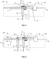
- FIG. 2 shows a further embodiment of an inventive optical roughness sensor 10 'for a coordinate measuring machine. Similar or equivalent elements in different figures are provided with the same reference numerals.
- the sensor 10 via a beam coupling device 11, a first beam splitter 13, a reflective surface 14 for providing the lateral position signal and in particular the reference signal, a guide rod 15 and a drive unit 16.
- the components mentioned act together in a similar manner as described above that is, the decoupling channel 12 can be guided by means of the drive 16 along the scan axis, wherein surface data can be detected due to a reflection of the Meßstrahlanteils 17.
- the roughness sensor 10 ' has an additional, second outcoupling path 22 with a second beam passage window for the bidirectional transmission of a first compensation component 27 of the measuring or useful radiation.
- the compensation radiation 27 is decoupled by means of a second beam splitter 23 from the optical radiation fed into the sensor 10 '.
- the second beam splitter 23 has a 50% transmissive or reflective coating. 50% of the supplied radiation is then coupled out as a compensation component 27 and 50% are used together for the measurement component 17 and the reference component.
- the first beam splitter 13 may have a 99% reflective coating, with 99% serve as a reference and 1% as a reference part.
- the second extraction path 22 of the roughness sensor is provided relative to it with a fixed positional relationship, i.
- the second such path 22 is fixedly and immovably arranged on the sensor (in particular in the sensor housing 18).
- the second decoupling path 22 thus provides a position-constant emission of the compensation beam component 27 with respect to the sensor 10.
- the signal of the local oscillator may be provided for this and all other embodiments of the invention shown alternatively or additionally by a first reflection at the end 11b of the fiber ferrule 11a (sleeve) (common path interferometry). All further reflexes can then interfere with this and / or another LO-reflex (LO: local oscillator).
- LO local oscillator
- the first compensation signal that can be generated thereby represents a distance of the sensor 10 'from the object. Since the second coupling-out path 22 remains unchanged in the lateral direction x, i. is substantially directed to a fixed point of the object, while the first Auskoppelpfad 12 is moved, thereby position changes can be determined independently of a roughness change.
- the first compensation signal makes it possible to detect and calculate vibrations or vibrations occurring in a coordinate measuring machine which carries the sensor 10 ', in particular in the z-direction. This happens on the assumption that during the roughness measurement with the moving measuring radiation 17, a distance measured via the second coupling-out path 22 remains constant. If deviations or variations are detected along this path, then there is an unwanted relative movement, which in turn can be processed time-resolved for the creation of a surface profile.
- This second embodiment thus provides a specific roughness sensor 10 'for use with a coordinate measuring machine (CMM), which is also able to compensate for possibly occurring vibrations and vibrations in the CMM or to provide the compensation.
- CMM coordinate measuring machine
- FIG. 3 shows a further embodiment of a roughness sensor 10 "according to the invention for the preferred use with a coordinate measuring machine.
- the embodiment is again based on a sensor 10 according to FIG. 1 ,
- the sensor 10 "has a fixedly positioned reference component 31 extending parallel to the scan axis S.
- the reference component 31 can be embodied, for example, as a reflecting surface, for example a mirror Blasting part 37 (Scancompensation part) provides.
- the scan compensation portion 37 is aligned with and reflected by the reference component 31.
- an inner (second) compensation signal is provided.
- the beam splitter 33 is connected to the decoupling path 17 and correspondingly movable together (in the x direction).
- the arrangement of reference component 31 and beam splitter 33 can hereby provide an internal compensation of the roughness sensor, wherein a linearity of the scanning movement of the first decoupling path 12 can be detected and monitored. From a superposition of the reference signal with the inner compensation signal, the distance can be derived.
- a desired distance is defined for the measurement with the roughness sensor 10 ", in the case of which it can be concluded via the scan movement along the scan axis, for example, that a flawless, linear scanning movement can be concluded.Distance of the distance can be recorded via the scan position and respective distances can be at respective lateral positions A possible offset, drift or vibration of the moving Meßstrahlauskopplers 12 can thus be detected and processed with the simultaneously detectable roughness values and thus also the measured surface profile.
- the amplitudes of the reflected signals provided by 14 and 31 can be selected to be a few orders of magnitude smaller than for the reference signal. This can e.g. be achieved by a low transmissivity (transmission) of the beam splitter 13.
- FIG. 4 shows an embodiment of a roughness sensor 10 '''according to the invention, which is a combination of the approaches of the Figures 2 and 3 represents.
- a roughness sensor 10 '' ' By means of such a combination of the approaches, all the concepts described above can be realized together in a roughness sensor 10 '' 'based on the different signals.
- This may provide a sensor 10 "'that can handle both internal scanning vibrations, e.g. caused by the drive unit 16 as well as making external vibrations compensatable as by a coordinate measuring machine (e.g., also by their drives) or other environmental influences.
- a coordinate measuring machine e.g., also by their drives
- substantially a coupled useful radiation may be sufficient, whereby this useful radiation in the sensor 10 '' 'can be divided into the required proportions, i. Measurement component, first (external) and second (internal) compensation component and lateral position measurement component.
- FIG. 5 shows a further embodiment of an inventive optical roughness sensor 40 for a coordinate measuring machine with optionally a distance reference element 41st
- the roughness sensor 40 has a beam coupling device 11, which in turn here is designed as a fiber coupling 11a with optics and provides the coupling and the extraction of optical radiation.
- the useful radiation is guided by means of an optical fiber in the sensor 40.
- the local oscillator is provided by a reflection of the input radiation at the end face 11b of the ferrule 11a of the optical fiber.
- the roughness sensor 40 also has a coupling unit (not shown) by means of which a modular and repeated coupling of the sensor 40 to a coordinate measuring machine, in particular with repeatedly highly accurate relative positioning, is made possible.
- the coupling unit can be designed to transmit optical and / or electrical signals.
- a beam deflecting element 13 ' (eg mirror) provided a deflection of the measuring radiation 17 within the housing 18.
- the measuring radiation can thereby be guided out of the sensor 40 on the underside of the housing 18 through a beam passage window 42. Reflected measuring radiation can be detected via the same path.
- the ferrule 11a or optical fiber can be guided to the beam passage window 42 and the end face 11b (the ferrule or the fiber) can form the beam passage window 42.
- a measurement can be realized by selectively guiding the sensor 40 along the surface to be measured.
- a measuring path can be defined in particular on the basis of a known object shape or a known surface profile.
- the guiding is preferably carried out by means of a coordinate measuring machine, the sensor 40 being fastened to a measuring head or to a suitable coupling of the CMM (modular).
- CMM module
- maintaining a constant or highly precisely known distance between the surface and the sensor is preferred. A deviation of this distance can lead to significant errors in a roughness measurement.
- such an expansion can achieve an accuracy for the measurement within the scope of the positioning accuracy of the CMM.
- a distance reference element 41 may optionally be provided on the sensor 40.
- the spacer reference element 41 is formed here as an example as a runner 41 and serves to be placed on a surface to be measured and moved for a measurement while maintaining the largest possible surface contact over the surface. Thus, a constant distance between surface and sensor 40 can be maintained during a measurement.
- a use of such a distance reference element 41 is advantageously also with a roughness sensor 10 of FIG. 1 conceivable.
- the sensor 10 can be placed on a surface by means of the distance reference element 41 In this case, a lateral movement can not be effected by a movement of the entire sensor 10 but by a lateral displacement of the coupling-out path 12 in the x-direction by means of the drive 16.
- the distance reference element 41 may be replaced by a e.g. be embodied in three-component edition, this being e.g. has three curved (e.g., spherical or semi-spherical) elements on the underside of the housing 18. This can provide a 3-punk pad for the sensor.
- a e.g. be embodied in three-component edition this being e.g. has three curved (e.g., spherical or semi-spherical) elements on the underside of the housing 18. This can provide a 3-punk pad for the sensor.
- FIG. 6 shows a coordinate measuring machine 1, exemplified as a gantry coordinate measuring machine. 1
- the coordinate measuring machine 1 has a base 2 on which a portal 3 is arranged so as to be movable in a first direction (y-direction).
- the portal 3 has two gantry beams, a bridge 4 and a pole or Z-pillar 5, wherein the gantry beams are connected to each other at their upper ends via the bridge 4.
- a carriage 6 Arranged on the bridge 4 is a carriage 6 which is movable along the bridge 4, ie in a second spatial direction (x-direction) connecting the two portal carriers.
- the rod or z-pillar 5 is movable in a third spatial direction (z-direction) and is guided in a receptacle of the carriage 6.
- the Z-pillar 5 is guided in bearings, which are part of the carriage 6.
- the three spatial directions x, y and z are aligned perpendicular to each other here, even if this is not a prerequisite for the present invention.
- the coordinate measuring machine 1 is provided for the determination of one or a plurality of measuring points on an object 9 and therefore has three linear guiding mechanisms for enabling the movement of a sensor 10 arranged on the z-pillar 5 in the three spatial directions x, y and z relative to the base 2 on.
- the sensor 10 is arranged by means of an interface 7 for modular recording of different sensors on the base 2 facing the lower free end of the z-pillar 5.
- the senor 10 is supplied by means of an optical fiber 8 with optical useful radiation.
- the optical fiber 8 additionally provides a transmission of the signals measured by the sensor 10 out of the sensor 10.
- Corresponding detectors for the signals and a signal processing are provided on the coordinate measuring machine 1.
- the transmission of the optical radiation can alternatively also be provided integrated in the interface 7.
- Each linear guide mechanism has an associated operator (in the x -, y - and z-direction). Furthermore, each linear guide mechanism has an associated measuring element for determining the position in the associated guide direction, for example, measurement scales for position determinations in the x -, y - and z-direction or linear encoder on.
- the measuring head with a roughness sensor 10 is according to FIG. 1 Provided.
- different types of sensor can be accommodated by means of the interface 7, for example tactile sensors with which a mechanical contact to an object surface to be measured is produced, or contactless measuring sensors, such as capacitive, inductive and optical sensors.
- the different sensors can also be kept in an exchange unit (not shown) and exchanged automatically, i. connected to the interface 7 and decoupled from the interface 7, are.
- the invention is not limited to gantry coordinate measuring machines, as in FIG. 1 shown. Rather, any known type of coordinate measuring machine which enables object surface measurement with an optical sensor is suitable for the invention.
- the coordinate measuring machine 1 also has a control and processing unit, with a processor and a data carrier.
- a control and processing unit By means of the control and processing unit, in particular drives of the coordinate measuring machine 1 are controlled and the measured data are stored and processed.
- the control and processing unit is designed to enable fully automatic measurement of object surfaces.
- control and processing unit may also be connected to a user console, in particular wireless e.g. via radio.
Landscapes
- Physics & Mathematics (AREA)
- General Physics & Mathematics (AREA)
- Length Measuring Devices By Optical Means (AREA)
Priority Applications (3)
| Application Number | Priority Date | Filing Date | Title |
|---|---|---|---|
| EP17183279.3A EP3435032B1 (fr) | 2017-07-26 | 2017-07-26 | Capteur optique de rugosité pour une machine de mesure de coordonnées |
| CN201810825143.4A CN109307487B (zh) | 2017-07-26 | 2018-07-25 | 用于坐标测量机的光学粗糙度传感器和坐标测量机 |
| US16/045,603 US10775150B2 (en) | 2017-07-26 | 2018-07-25 | Optical roughness sensor for a coordinate measuring machine |
Applications Claiming Priority (1)
| Application Number | Priority Date | Filing Date | Title |
|---|---|---|---|
| EP17183279.3A EP3435032B1 (fr) | 2017-07-26 | 2017-07-26 | Capteur optique de rugosité pour une machine de mesure de coordonnées |
Publications (2)
| Publication Number | Publication Date |
|---|---|
| EP3435032A1 true EP3435032A1 (fr) | 2019-01-30 |
| EP3435032B1 EP3435032B1 (fr) | 2020-11-11 |
Family
ID=59409257
Family Applications (1)
| Application Number | Title | Priority Date | Filing Date |
|---|---|---|---|
| EP17183279.3A Active EP3435032B1 (fr) | 2017-07-26 | 2017-07-26 | Capteur optique de rugosité pour une machine de mesure de coordonnées |
Country Status (3)
| Country | Link |
|---|---|
| US (1) | US10775150B2 (fr) |
| EP (1) | EP3435032B1 (fr) |
| CN (1) | CN109307487B (fr) |
Cited By (1)
| Publication number | Priority date | Publication date | Assignee | Title |
|---|---|---|---|---|
| EP4339556A1 (fr) | 2022-09-16 | 2024-03-20 | Carl Zeiss Industrielle Messtechnik GmbH | Procédé et dispositif de détermination de propriétés de surface d'une pièce |
Families Citing this family (4)
| Publication number | Priority date | Publication date | Assignee | Title |
|---|---|---|---|---|
| DE102015209193A1 (de) * | 2015-05-20 | 2016-11-24 | Carl Zeiss Industrielle Messtechnik Gmbh | Verfahren zur Erfassung dynamischer Schwingungen eines Rauheitssensors, Verfahren zur Vermessung der Rauheit einer Werkstückoberfläche, Computerprogrammprodukt sowie Messgerät eingerichtet zur Durchführung der Verfahren. |
| US10768284B1 (en) * | 2019-05-22 | 2020-09-08 | Pony Ai Inc. | Systems and methods for using audio cue for alignment |
| US12098914B2 (en) * | 2022-09-29 | 2024-09-24 | Applied Materials, Inc. | Surface roughness and emissivity determination |
| CN116086287B (zh) * | 2023-02-20 | 2026-01-30 | 宁波市政工程建设集团股份有限公司 | 一种市政工程测绘系统及其测绘方法 |
Citations (8)
| Publication number | Priority date | Publication date | Assignee | Title |
|---|---|---|---|---|
| DE4325337A1 (de) | 1992-07-31 | 1994-02-03 | Dea Spa | Meßmaschine |
| DE4325347A1 (de) | 1992-07-31 | 1994-02-03 | Dea Spa | Anordnung zum Tragen und Führen eines beweglichen Organs |
| US5402582A (en) | 1993-02-23 | 1995-04-04 | Faro Technologies Inc. | Three dimensional coordinate measuring apparatus |
| DE19735975A1 (de) | 1997-08-19 | 1999-03-04 | Leitz Brown & Sharpe Mestechni | Verfahren zur rechnerischen Vibrationsunterdrückung bei Koordinatenmeßgeräten sowie Koordinatenmeßgerät zur Durchführung des Verfahrens |
| EP1474650A2 (fr) | 2002-02-14 | 2004-11-10 | Faro Technologies Inc. | Machine de mesure de coordonnees portative amelioree |
| EP2463615A2 (fr) * | 2010-12-08 | 2012-06-13 | Robert Bosch GmbH | Système de balayage pour la détection de la forme, du diamètre et/ou de la rugosité d'une surface |
| EP2690395A1 (fr) * | 2012-07-24 | 2014-01-29 | Hexagon Technology Center GmbH | Dispositif de mesure de distance interférométrique et procédé associé |
| US20160091299A1 (en) * | 2014-08-29 | 2016-03-31 | Robert Smythe | Interferometric non-contact optical probe and measurement |
Family Cites Families (13)
| Publication number | Priority date | Publication date | Assignee | Title |
|---|---|---|---|---|
| GB2256476B (en) | 1991-05-30 | 1995-09-27 | Rank Taylor Hobson Ltd | Positional measurement |
| CN100483071C (zh) | 2006-01-23 | 2009-04-29 | 贵州大学 | 基于垂直位移扫描的非接触式表面形貌测量方法及测量仪 |
| DE102007017664A1 (de) * | 2007-04-14 | 2008-10-16 | Carl Mahr Holding Gmbh | Interferenzoptisches Tastschnittgerät |
| DE102015105613B4 (de) * | 2015-04-13 | 2023-08-31 | Carl Zeiss Industrielle Messtechnik Gmbh | Auflicht-Beleuchtung für variablen Arbeitsabstand |
| CN205482840U (zh) | 2016-01-05 | 2016-08-17 | 哈尔滨理工大学 | 一种基于Mach-Zehnder的双光束元件表面粗糙度测量装置 |
| EP3258211B1 (fr) * | 2016-06-17 | 2023-12-13 | Hexagon Technology Center GmbH | Détermination des propriétés de réflexion d'objet par rapport à une mesure optique particulière |
| JP7000037B2 (ja) * | 2017-05-12 | 2022-01-19 | 株式会社ミツトヨ | 三次元測定機および三次元測定方法 |
| JP7272743B2 (ja) * | 2017-09-05 | 2023-05-12 | 株式会社ミツトヨ | 表面性状測定装置の制御方法 |
| US20190094010A1 (en) * | 2017-09-28 | 2019-03-28 | Hexagon Metrology, Inc. | Systems and methods for measuring various properties of an object |
| DE102017220876B4 (de) * | 2017-11-22 | 2020-12-24 | Ford Global Technologies, Llc | Verfahren und Vorrichtung zur Positions- und Lagebestimmung |
| JP6979885B2 (ja) * | 2018-01-17 | 2021-12-15 | 株式会社ミツトヨ | 3d形状のオートトレース方法及び測定機 |
| US20190242702A1 (en) * | 2018-02-02 | 2019-08-08 | Hexagon Metrology, Inc. | Method and Apparatus for Measuring Surface Finish of a Workpiece |
| EP3581881B1 (fr) * | 2018-06-15 | 2025-03-19 | Hexagon Technology Center GmbH | Mesure de surface au moyen de la fluorescence excitée |
-
2017
- 2017-07-26 EP EP17183279.3A patent/EP3435032B1/fr active Active
-
2018
- 2018-07-25 US US16/045,603 patent/US10775150B2/en active Active
- 2018-07-25 CN CN201810825143.4A patent/CN109307487B/zh active Active
Patent Citations (8)
| Publication number | Priority date | Publication date | Assignee | Title |
|---|---|---|---|---|
| DE4325337A1 (de) | 1992-07-31 | 1994-02-03 | Dea Spa | Meßmaschine |
| DE4325347A1 (de) | 1992-07-31 | 1994-02-03 | Dea Spa | Anordnung zum Tragen und Führen eines beweglichen Organs |
| US5402582A (en) | 1993-02-23 | 1995-04-04 | Faro Technologies Inc. | Three dimensional coordinate measuring apparatus |
| DE19735975A1 (de) | 1997-08-19 | 1999-03-04 | Leitz Brown & Sharpe Mestechni | Verfahren zur rechnerischen Vibrationsunterdrückung bei Koordinatenmeßgeräten sowie Koordinatenmeßgerät zur Durchführung des Verfahrens |
| EP1474650A2 (fr) | 2002-02-14 | 2004-11-10 | Faro Technologies Inc. | Machine de mesure de coordonnees portative amelioree |
| EP2463615A2 (fr) * | 2010-12-08 | 2012-06-13 | Robert Bosch GmbH | Système de balayage pour la détection de la forme, du diamètre et/ou de la rugosité d'une surface |
| EP2690395A1 (fr) * | 2012-07-24 | 2014-01-29 | Hexagon Technology Center GmbH | Dispositif de mesure de distance interférométrique et procédé associé |
| US20160091299A1 (en) * | 2014-08-29 | 2016-03-31 | Robert Smythe | Interferometric non-contact optical probe and measurement |
Cited By (1)
| Publication number | Priority date | Publication date | Assignee | Title |
|---|---|---|---|---|
| EP4339556A1 (fr) | 2022-09-16 | 2024-03-20 | Carl Zeiss Industrielle Messtechnik GmbH | Procédé et dispositif de détermination de propriétés de surface d'une pièce |
Also Published As
| Publication number | Publication date |
|---|---|
| EP3435032B1 (fr) | 2020-11-11 |
| US20190033056A1 (en) | 2019-01-31 |
| CN109307487B (zh) | 2020-11-24 |
| CN109307487A (zh) | 2019-02-05 |
| US10775150B2 (en) | 2020-09-15 |
Similar Documents
| Publication | Publication Date | Title |
|---|---|---|
| EP0330901B1 (fr) | Système de mesure et d'essai à plusieurs coordonnées | |
| EP1407224B1 (fr) | Procede pour mesurer des proprietes superficielles et dispositif de mesure de coordonnees | |
| EP2762832B1 (fr) | Mesure optique des points individuels | |
| EP3435032B1 (fr) | Capteur optique de rugosité pour une machine de mesure de coordonnées | |
| EP2643129B2 (fr) | Procédé de commande d'un appareil de mesure de coordonnées | |
| DE102015217637B4 (de) | Betreiben eines konfokalen Weißlichtsensors an einem Koordinatenmessgerät und Anordnung | |
| DE102016124549B4 (de) | Messsystem | |
| DE102011011065B4 (de) | Verfahren und Vorrichtung zur hochpräzisen Vermessung von Oberflächen | |
| EP2185890A1 (fr) | Procédé et appareil de mesure pour arpenter des surfaces | |
| EP1347266B1 (fr) | Dispositif de mesure d' un objet | |
| EP3351893A1 (fr) | Appareil et méthode pour mesurer au moins une longueur | |
| DE112006001423B4 (de) | Koordinatenmessgerät sowie Verfahren zum Messen eines Objektes mit einem Koordinatenmessgerät | |
| CH666547A5 (de) | Optisch-elektronisches messverfahren, eine dafuer erforderliche einrichtung und deren verwendung. | |
| EP3569976A1 (fr) | Tête de mesure de rugosité, dispositif avec ladite tête de mesure et utilisation correspondante | |
| DE10258579B4 (de) | Messeinrichtung | |
| EP0771406B1 (fr) | Dispositif et procede de mesure et de calcul de parametres geometriques d'un corps | |
| DE4421302C1 (de) | Verfahren zur Eliminierung des Rollwinkels einer Meßachse einer Koordinatenmeßmaschine sowie Vorrichtung zur Durchführung des Verfahrens | |
| DE112018004038T5 (de) | Messung der Position von Objekten im Raum | |
| EP3351895B1 (fr) | Appareil de mesure et procédé pour opérer un appareil de mesure | |
| DE102012104017A1 (de) | Messeinrichtung und Verfahren zur Messung von Kugeln | |
| DE102007017664A1 (de) | Interferenzoptisches Tastschnittgerät | |
| DE102016013550B3 (de) | Profilmesssystem für eine Rauheits- und Konturmessung an einer Oberfläche eines Werkstücks | |
| DE10349946B4 (de) | Anordnung zur Messung von Oberflächeneigenschaften | |
| DE102019134939B4 (de) | Vorrichtung und Verfahren zur Erfassung einer Lage eines Körpers sowie Koordinatenmessgerät | |
| DE102018208189A1 (de) | Verfahren und Vorrichtung zum Ermitteln der Torsionsfehler einer Maschinenachse |
Legal Events
| Date | Code | Title | Description |
|---|---|---|---|
| PUAI | Public reference made under article 153(3) epc to a published international application that has entered the european phase |
Free format text: ORIGINAL CODE: 0009012 |
|
| STAA | Information on the status of an ep patent application or granted ep patent |
Free format text: STATUS: THE APPLICATION HAS BEEN PUBLISHED |
|
| AK | Designated contracting states |
Kind code of ref document: A1 Designated state(s): AL AT BE BG CH CY CZ DE DK EE ES FI FR GB GR HR HU IE IS IT LI LT LU LV MC MK MT NL NO PL PT RO RS SE SI SK SM TR |
|
| AX | Request for extension of the european patent |
Extension state: BA ME |
|
| STAA | Information on the status of an ep patent application or granted ep patent |
Free format text: STATUS: REQUEST FOR EXAMINATION WAS MADE |
|
| 17P | Request for examination filed |
Effective date: 20190730 |
|
| RBV | Designated contracting states (corrected) |
Designated state(s): AL AT BE BG CH CY CZ DE DK EE ES FI FR GB GR HR HU IE IS IT LI LT LU LV MC MK MT NL NO PL PT RO RS SE SI SK SM TR |
|
| STAA | Information on the status of an ep patent application or granted ep patent |
Free format text: STATUS: EXAMINATION IS IN PROGRESS |
|
| 17Q | First examination report despatched |
Effective date: 20191220 |
|
| GRAP | Despatch of communication of intention to grant a patent |
Free format text: ORIGINAL CODE: EPIDOSNIGR1 |
|
| STAA | Information on the status of an ep patent application or granted ep patent |
Free format text: STATUS: GRANT OF PATENT IS INTENDED |
|
| INTG | Intention to grant announced |
Effective date: 20200812 |
|
| RIN1 | Information on inventor provided before grant (corrected) |
Inventor name: JENSEN, THOMAS |
|
| GRAS | Grant fee paid |
Free format text: ORIGINAL CODE: EPIDOSNIGR3 |
|
| GRAA | (expected) grant |
Free format text: ORIGINAL CODE: 0009210 |
|
| STAA | Information on the status of an ep patent application or granted ep patent |
Free format text: STATUS: THE PATENT HAS BEEN GRANTED |
|
| AK | Designated contracting states |
Kind code of ref document: B1 Designated state(s): AL AT BE BG CH CY CZ DE DK EE ES FI FR GB GR HR HU IE IS IT LI LT LU LV MC MK MT NL NO PL PT RO RS SE SI SK SM TR |
|
| REG | Reference to a national code |
Ref country code: GB Ref legal event code: FG4D Free format text: NOT ENGLISH |
|
| REG | Reference to a national code |
Ref country code: CH Ref legal event code: EP |
|
| REG | Reference to a national code |
Ref country code: AT Ref legal event code: REF Ref document number: 1333903 Country of ref document: AT Kind code of ref document: T Effective date: 20201115 |
|
| REG | Reference to a national code |
Ref country code: IE Ref legal event code: FG4D Free format text: LANGUAGE OF EP DOCUMENT: GERMAN |
|
| REG | Reference to a national code |
Ref country code: DE Ref legal event code: R096 Ref document number: 502017008120 Country of ref document: DE |
|
| REG | Reference to a national code |
Ref country code: NL Ref legal event code: MP Effective date: 20201111 |
|
| PG25 | Lapsed in a contracting state [announced via postgrant information from national office to epo] |
Ref country code: FI Free format text: LAPSE BECAUSE OF FAILURE TO SUBMIT A TRANSLATION OF THE DESCRIPTION OR TO PAY THE FEE WITHIN THE PRESCRIBED TIME-LIMIT Effective date: 20201111 Ref country code: GR Free format text: LAPSE BECAUSE OF FAILURE TO SUBMIT A TRANSLATION OF THE DESCRIPTION OR TO PAY THE FEE WITHIN THE PRESCRIBED TIME-LIMIT Effective date: 20210212 Ref country code: RS Free format text: LAPSE BECAUSE OF FAILURE TO SUBMIT A TRANSLATION OF THE DESCRIPTION OR TO PAY THE FEE WITHIN THE PRESCRIBED TIME-LIMIT Effective date: 20201111 Ref country code: PT Free format text: LAPSE BECAUSE OF FAILURE TO SUBMIT A TRANSLATION OF THE DESCRIPTION OR TO PAY THE FEE WITHIN THE PRESCRIBED TIME-LIMIT Effective date: 20210311 Ref country code: NO Free format text: LAPSE BECAUSE OF FAILURE TO SUBMIT A TRANSLATION OF THE DESCRIPTION OR TO PAY THE FEE WITHIN THE PRESCRIBED TIME-LIMIT Effective date: 20210211 |
|
| PG25 | Lapsed in a contracting state [announced via postgrant information from national office to epo] |
Ref country code: BG Free format text: LAPSE BECAUSE OF FAILURE TO SUBMIT A TRANSLATION OF THE DESCRIPTION OR TO PAY THE FEE WITHIN THE PRESCRIBED TIME-LIMIT Effective date: 20210211 Ref country code: PL Free format text: LAPSE BECAUSE OF FAILURE TO SUBMIT A TRANSLATION OF THE DESCRIPTION OR TO PAY THE FEE WITHIN THE PRESCRIBED TIME-LIMIT Effective date: 20201111 Ref country code: IS Free format text: LAPSE BECAUSE OF FAILURE TO SUBMIT A TRANSLATION OF THE DESCRIPTION OR TO PAY THE FEE WITHIN THE PRESCRIBED TIME-LIMIT Effective date: 20210311 Ref country code: LV Free format text: LAPSE BECAUSE OF FAILURE TO SUBMIT A TRANSLATION OF THE DESCRIPTION OR TO PAY THE FEE WITHIN THE PRESCRIBED TIME-LIMIT Effective date: 20201111 Ref country code: SE Free format text: LAPSE BECAUSE OF FAILURE TO SUBMIT A TRANSLATION OF THE DESCRIPTION OR TO PAY THE FEE WITHIN THE PRESCRIBED TIME-LIMIT Effective date: 20201111 |
|
| REG | Reference to a national code |
Ref country code: LT Ref legal event code: MG9D |
|
| PG25 | Lapsed in a contracting state [announced via postgrant information from national office to epo] |
Ref country code: HR Free format text: LAPSE BECAUSE OF FAILURE TO SUBMIT A TRANSLATION OF THE DESCRIPTION OR TO PAY THE FEE WITHIN THE PRESCRIBED TIME-LIMIT Effective date: 20201111 |
|
| PG25 | Lapsed in a contracting state [announced via postgrant information from national office to epo] |
Ref country code: RO Free format text: LAPSE BECAUSE OF FAILURE TO SUBMIT A TRANSLATION OF THE DESCRIPTION OR TO PAY THE FEE WITHIN THE PRESCRIBED TIME-LIMIT Effective date: 20201111 Ref country code: SK Free format text: LAPSE BECAUSE OF FAILURE TO SUBMIT A TRANSLATION OF THE DESCRIPTION OR TO PAY THE FEE WITHIN THE PRESCRIBED TIME-LIMIT Effective date: 20201111 Ref country code: SM Free format text: LAPSE BECAUSE OF FAILURE TO SUBMIT A TRANSLATION OF THE DESCRIPTION OR TO PAY THE FEE WITHIN THE PRESCRIBED TIME-LIMIT Effective date: 20201111 Ref country code: LT Free format text: LAPSE BECAUSE OF FAILURE TO SUBMIT A TRANSLATION OF THE DESCRIPTION OR TO PAY THE FEE WITHIN THE PRESCRIBED TIME-LIMIT Effective date: 20201111 Ref country code: CZ Free format text: LAPSE BECAUSE OF FAILURE TO SUBMIT A TRANSLATION OF THE DESCRIPTION OR TO PAY THE FEE WITHIN THE PRESCRIBED TIME-LIMIT Effective date: 20201111 Ref country code: EE Free format text: LAPSE BECAUSE OF FAILURE TO SUBMIT A TRANSLATION OF THE DESCRIPTION OR TO PAY THE FEE WITHIN THE PRESCRIBED TIME-LIMIT Effective date: 20201111 |
|
| REG | Reference to a national code |
Ref country code: DE Ref legal event code: R097 Ref document number: 502017008120 Country of ref document: DE |
|
| PG25 | Lapsed in a contracting state [announced via postgrant information from national office to epo] |
Ref country code: DK Free format text: LAPSE BECAUSE OF FAILURE TO SUBMIT A TRANSLATION OF THE DESCRIPTION OR TO PAY THE FEE WITHIN THE PRESCRIBED TIME-LIMIT Effective date: 20201111 |
|
| PLBE | No opposition filed within time limit |
Free format text: ORIGINAL CODE: 0009261 |
|
| STAA | Information on the status of an ep patent application or granted ep patent |
Free format text: STATUS: NO OPPOSITION FILED WITHIN TIME LIMIT |
|
| 26N | No opposition filed |
Effective date: 20210812 |
|
| PG25 | Lapsed in a contracting state [announced via postgrant information from national office to epo] |
Ref country code: IT Free format text: LAPSE BECAUSE OF FAILURE TO SUBMIT A TRANSLATION OF THE DESCRIPTION OR TO PAY THE FEE WITHIN THE PRESCRIBED TIME-LIMIT Effective date: 20201111 Ref country code: AL Free format text: LAPSE BECAUSE OF FAILURE TO SUBMIT A TRANSLATION OF THE DESCRIPTION OR TO PAY THE FEE WITHIN THE PRESCRIBED TIME-LIMIT Effective date: 20201111 Ref country code: NL Free format text: LAPSE BECAUSE OF FAILURE TO SUBMIT A TRANSLATION OF THE DESCRIPTION OR TO PAY THE FEE WITHIN THE PRESCRIBED TIME-LIMIT Effective date: 20201111 |
|
| PG25 | Lapsed in a contracting state [announced via postgrant information from national office to epo] |
Ref country code: SI Free format text: LAPSE BECAUSE OF FAILURE TO SUBMIT A TRANSLATION OF THE DESCRIPTION OR TO PAY THE FEE WITHIN THE PRESCRIBED TIME-LIMIT Effective date: 20201111 |
|
| PG25 | Lapsed in a contracting state [announced via postgrant information from national office to epo] |
Ref country code: ES Free format text: LAPSE BECAUSE OF FAILURE TO SUBMIT A TRANSLATION OF THE DESCRIPTION OR TO PAY THE FEE WITHIN THE PRESCRIBED TIME-LIMIT Effective date: 20201111 |
|
| REG | Reference to a national code |
Ref country code: CH Ref legal event code: PL |
|
| PG25 | Lapsed in a contracting state [announced via postgrant information from national office to epo] |
Ref country code: MC Free format text: LAPSE BECAUSE OF FAILURE TO SUBMIT A TRANSLATION OF THE DESCRIPTION OR TO PAY THE FEE WITHIN THE PRESCRIBED TIME-LIMIT Effective date: 20201111 |
|
| REG | Reference to a national code |
Ref country code: BE Ref legal event code: MM Effective date: 20210731 |
|
| PG25 | Lapsed in a contracting state [announced via postgrant information from national office to epo] |
Ref country code: LI Free format text: LAPSE BECAUSE OF NON-PAYMENT OF DUE FEES Effective date: 20210731 Ref country code: CH Free format text: LAPSE BECAUSE OF NON-PAYMENT OF DUE FEES Effective date: 20210731 |
|
| PG25 | Lapsed in a contracting state [announced via postgrant information from national office to epo] |
Ref country code: IS Free format text: LAPSE BECAUSE OF FAILURE TO SUBMIT A TRANSLATION OF THE DESCRIPTION OR TO PAY THE FEE WITHIN THE PRESCRIBED TIME-LIMIT Effective date: 20210311 Ref country code: LU Free format text: LAPSE BECAUSE OF NON-PAYMENT OF DUE FEES Effective date: 20210726 |
|
| PG25 | Lapsed in a contracting state [announced via postgrant information from national office to epo] |
Ref country code: IE Free format text: LAPSE BECAUSE OF NON-PAYMENT OF DUE FEES Effective date: 20210726 Ref country code: BE Free format text: LAPSE BECAUSE OF NON-PAYMENT OF DUE FEES Effective date: 20210731 |
|
| PG25 | Lapsed in a contracting state [announced via postgrant information from national office to epo] |
Ref country code: CY Free format text: LAPSE BECAUSE OF FAILURE TO SUBMIT A TRANSLATION OF THE DESCRIPTION OR TO PAY THE FEE WITHIN THE PRESCRIBED TIME-LIMIT Effective date: 20201111 |
|
| PG25 | Lapsed in a contracting state [announced via postgrant information from national office to epo] |
Ref country code: HU Free format text: LAPSE BECAUSE OF FAILURE TO SUBMIT A TRANSLATION OF THE DESCRIPTION OR TO PAY THE FEE WITHIN THE PRESCRIBED TIME-LIMIT; INVALID AB INITIO Effective date: 20170726 |
|
| REG | Reference to a national code |
Ref country code: AT Ref legal event code: MM01 Ref document number: 1333903 Country of ref document: AT Kind code of ref document: T Effective date: 20220726 |
|
| PG25 | Lapsed in a contracting state [announced via postgrant information from national office to epo] |
Ref country code: AT Free format text: LAPSE BECAUSE OF NON-PAYMENT OF DUE FEES Effective date: 20220726 |
|
| PG25 | Lapsed in a contracting state [announced via postgrant information from national office to epo] |
Ref country code: MK Free format text: LAPSE BECAUSE OF FAILURE TO SUBMIT A TRANSLATION OF THE DESCRIPTION OR TO PAY THE FEE WITHIN THE PRESCRIBED TIME-LIMIT Effective date: 20201111 |
|
| PG25 | Lapsed in a contracting state [announced via postgrant information from national office to epo] |
Ref country code: TR Free format text: LAPSE BECAUSE OF FAILURE TO SUBMIT A TRANSLATION OF THE DESCRIPTION OR TO PAY THE FEE WITHIN THE PRESCRIBED TIME-LIMIT Effective date: 20201111 |
|
| PG25 | Lapsed in a contracting state [announced via postgrant information from national office to epo] |
Ref country code: MT Free format text: LAPSE BECAUSE OF FAILURE TO SUBMIT A TRANSLATION OF THE DESCRIPTION OR TO PAY THE FEE WITHIN THE PRESCRIBED TIME-LIMIT Effective date: 20201111 |
|
| PGFP | Annual fee paid to national office [announced via postgrant information from national office to epo] |
Ref country code: DE Payment date: 20250722 Year of fee payment: 9 |
|
| PGFP | Annual fee paid to national office [announced via postgrant information from national office to epo] |
Ref country code: GB Payment date: 20250722 Year of fee payment: 9 |
|
| PGFP | Annual fee paid to national office [announced via postgrant information from national office to epo] |
Ref country code: FR Payment date: 20250725 Year of fee payment: 9 |
|
| REG | Reference to a national code |
Ref country code: DE Ref legal event code: R081 Ref document number: 502017008120 Country of ref document: DE Owner name: HEXAGON INNOVATION HUB GMBH, CH Free format text: FORMER OWNER: HEXAGON TECHNOLOGY CENTER GMBH, HEERBRUGG, CH |
|
| REG | Reference to a national code |
Ref country code: GB Ref legal event code: 732E Free format text: REGISTERED BETWEEN 20260305 AND 20260311 |