EP3435078A2 - Lit à garnissage - Google Patents
Lit à garnissage Download PDFInfo
- Publication number
- EP3435078A2 EP3435078A2 EP18181849.3A EP18181849A EP3435078A2 EP 3435078 A2 EP3435078 A2 EP 3435078A2 EP 18181849 A EP18181849 A EP 18181849A EP 3435078 A2 EP3435078 A2 EP 3435078A2
- Authority
- EP
- European Patent Office
- Prior art keywords
- packed bed
- housing
- components
- male
- axially
- Prior art date
- Legal status (The legal status is an assumption and is not a legal conclusion. Google has not performed a legal analysis and makes no representation as to the accuracy of the status listed.)
- Withdrawn
Links
- 238000012856 packing Methods 0.000 claims description 25
- 229920000642 polymer Polymers 0.000 claims description 3
- 239000002184 metal Substances 0.000 claims 2
- 239000000463 material Substances 0.000 description 26
- 238000004128 high performance liquid chromatography Methods 0.000 description 12
- 239000012530 fluid Substances 0.000 description 8
- 238000001195 ultra high performance liquid chromatography Methods 0.000 description 8
- 238000004895 liquid chromatography mass spectrometry Methods 0.000 description 7
- 238000007789 sealing Methods 0.000 description 7
- 239000000126 substance Substances 0.000 description 7
- 238000000034 method Methods 0.000 description 5
- 239000004696 Poly ether ether ketone Substances 0.000 description 4
- 238000004458 analytical method Methods 0.000 description 4
- 230000000712 assembly Effects 0.000 description 4
- 238000000429 assembly Methods 0.000 description 4
- 238000004891 communication Methods 0.000 description 4
- 229920002530 polyetherether ketone Polymers 0.000 description 4
- 230000008901 benefit Effects 0.000 description 3
- JUPQTSLXMOCDHR-UHFFFAOYSA-N benzene-1,4-diol;bis(4-fluorophenyl)methanone Chemical compound OC1=CC=C(O)C=C1.C1=CC(F)=CC=C1C(=O)C1=CC=C(F)C=C1 JUPQTSLXMOCDHR-UHFFFAOYSA-N 0.000 description 3
- 238000001914 filtration Methods 0.000 description 3
- 238000004519 manufacturing process Methods 0.000 description 3
- 230000005526 G1 to G0 transition Effects 0.000 description 2
- 230000006835 compression Effects 0.000 description 2
- 238000007906 compression Methods 0.000 description 2
- 230000014759 maintenance of location Effects 0.000 description 2
- 230000013011 mating Effects 0.000 description 2
- 238000003466 welding Methods 0.000 description 2
- 230000002745 absorbent Effects 0.000 description 1
- 239000002250 absorbent Substances 0.000 description 1
- 239000003463 adsorbent Substances 0.000 description 1
- 230000000274 adsorptive effect Effects 0.000 description 1
- 239000011324 bead Substances 0.000 description 1
- 238000005219 brazing Methods 0.000 description 1
- 238000009614 chemical analysis method Methods 0.000 description 1
- 238000004440 column chromatography Methods 0.000 description 1
- 150000001875 compounds Chemical class 0.000 description 1
- 239000012141 concentrate Substances 0.000 description 1
- 238000002788 crimping Methods 0.000 description 1
- 238000013461 design Methods 0.000 description 1
- 239000003599 detergent Substances 0.000 description 1
- 230000003993 interaction Effects 0.000 description 1
- 238000004811 liquid chromatography Methods 0.000 description 1
- 238000004949 mass spectrometry Methods 0.000 description 1
- 239000000203 mixture Substances 0.000 description 1
- 239000002245 particle Substances 0.000 description 1
- 238000012545 processing Methods 0.000 description 1
- 230000001105 regulatory effect Effects 0.000 description 1
- 230000035945 sensitivity Effects 0.000 description 1
- 238000000926 separation method Methods 0.000 description 1
- 239000002904 solvent Substances 0.000 description 1
- 238000011895 specific detection Methods 0.000 description 1
Images


Classifications
-
- B—PERFORMING OPERATIONS; TRANSPORTING
- B01—PHYSICAL OR CHEMICAL PROCESSES OR APPARATUS IN GENERAL
- B01D—SEPARATION
- B01D15/00—Separating processes involving the treatment of liquids with solid sorbents; Apparatus therefor
- B01D15/08—Selective adsorption, e.g. chromatography
- B01D15/10—Selective adsorption, e.g. chromatography characterised by constructional or operational features
- B01D15/22—Selective adsorption, e.g. chromatography characterised by constructional or operational features relating to the construction of the column
-
- G—PHYSICS
- G01—MEASURING; TESTING
- G01N—INVESTIGATING OR ANALYSING MATERIALS BY DETERMINING THEIR CHEMICAL OR PHYSICAL PROPERTIES
- G01N30/00—Investigating or analysing materials by separation into components using adsorption, absorption or similar phenomena or using ion-exchange, e.g. chromatography or field flow fractionation
- G01N30/02—Column chromatography
- G01N30/60—Construction of the column
-
- G—PHYSICS
- G01—MEASURING; TESTING
- G01N—INVESTIGATING OR ANALYSING MATERIALS BY DETERMINING THEIR CHEMICAL OR PHYSICAL PROPERTIES
- G01N30/00—Investigating or analysing materials by separation into components using adsorption, absorption or similar phenomena or using ion-exchange, e.g. chromatography or field flow fractionation
- G01N30/02—Column chromatography
- G01N2030/022—Column chromatography characterised by the kind of separation mechanism
- G01N2030/027—Liquid chromatography
-
- G—PHYSICS
- G01—MEASURING; TESTING
- G01N—INVESTIGATING OR ANALYSING MATERIALS BY DETERMINING THEIR CHEMICAL OR PHYSICAL PROPERTIES
- G01N30/00—Investigating or analysing materials by separation into components using adsorption, absorption or similar phenomena or using ion-exchange, e.g. chromatography or field flow fractionation
- G01N30/02—Column chromatography
- G01N30/50—Conditioning of the sorbent material or stationary liquid
- G01N30/56—Packing methods or coating methods
-
- G—PHYSICS
- G01—MEASURING; TESTING
- G01N—INVESTIGATING OR ANALYSING MATERIALS BY DETERMINING THEIR CHEMICAL OR PHYSICAL PROPERTIES
- G01N30/00—Investigating or analysing materials by separation into components using adsorption, absorption or similar phenomena or using ion-exchange, e.g. chromatography or field flow fractionation
- G01N30/02—Column chromatography
- G01N30/60—Construction of the column
- G01N30/6004—Construction of the column end pieces
- G01N30/603—Construction of the column end pieces retaining the stationary phase, e.g. Frits
Definitions
- High performance liquid chromatography or high pressure liquid chromatography, HPLC
- UHPLC ultra high performance liquid chromatography
- HPLC and UHPLC utilize an HPLC column that holds chromatographic packing material (stationary phase), a pump that moves the mobile phase(s) through the HPLC column, and a detector that shows the retention times of the molecules. Retention time varies depending on the interactions between the stationary phase, the molecules being analyzed, and the solvent(s) used.
- HPLC analysis the sample is pumped through the HPLC column under an elevated pressure, typically at 300 to 6,000 psi, and in UHPLC, analysis, system pressure extends upward to 1400 bar or 20,000 psi or higher.
- LC/MS Liquid chromatography-mass spectrometry
- LC/MS is an analytical chemistry technique that combines the physical separation capabilities of liquid chromatography with the mass analysis capabilities of mass spectrometry.
- LC/MS is a powerful technique used for many applications which has very high sensitivity and specificity. Generally its application is oriented towards the specific detection and potential identification of chemicals in the presence of other chemicals (in a complex mixture).
- fitting assemblies such as those described in U.S. Pat. Nos. 8,696,902 ; 5,525,303 ; 5,669,637 ; 5,730,943 ; 5,911,954 ; 6,000,916 ; and 6,095,572 , the entire disclosures of which are incorporated by reference herein.
- the fitting assemblies may include first and second fitting subassemblies that receive an insert or packed bed therebetween to place the packed bed into fluid communication with the tubing.
- the packed bed may be a trap column, which is an internal packing material that uses the adsorptive properties of analytes to effectively concentrate dilute samples, desalt, remove detergents, etc., or another type of filter assembly or conduit.
- the packed bed may include first and second opposing male fittings that are sealable within female cavities of the first and second fitting subassemblies. It is advantageous if the fitting assembly and the packed bed provide a true zero-dead-volume connection between the analytical components to minimize dead space in the flow path.
- the internal components of the packed bed must be able to withstand the pressures of the HPLC, UHPLC, and LC/MS analyses while minimizing internal swept volume.
- many packed beds involve complicated and/or expensive manufacturing or assembly techniques, such as using screw threads, welding, or brazing to capture the internal components of the packed bed, such as the packed beds shown and described in "Quarter Turn Connect Fitting," U.S. Patent No. 6,095,572, issued August 1, 2000 ; "Assembly for placing an insert into communication with an analytical chemical instrument," U.S. Patent No. 8,307,541, issued November 13, 2012 ; and "High Pressure Connect Fitting," U.S. Patent No. 8,696,902, issued April 15, 2014 , the entire disclosures of which are incorporated by reference herein.
- a packed bed includes a housing and at least one packed bed component disposed within the housing.
- the housing includes a first integral end configured to axially retain packed bed components within the housing.
- the housing further includes a second integral end configured to axially receive packed bed components within the housing in a first, open position and axially retain the packed bed components within the housing in a second, closed position.
- the second end is configured to axially receive packed bed components within the housing in a first, uncrimped position and axially retain the packed bed components within the housing in a second, crimped position
- references to directions such as “forward,” “rearward,” “upward,” “downward,” “vertical,” “horizontal,” “open,” “closed,” etc. These references and other similar references in the present application are only to assist in helping describe and understand the present invention and are not intended to limit the present invention to these directions. Also, references to “packed bed,” “insert,” “column,” “trap column,” “filter assembly,” or similar are understood to be interchangeable and are not meant to be limiting in nature.
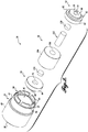
- a packed bed 20 formed in accordance with an exemplary embodiment of the present disclosure is provided.
- the packed bed 20 is generally configured to be used in a fitting assembly, such as one of the fitting assemblies described in U.S. Pat. Nos. 8,696,902 ; 5,525,303 ; 5,669,637 ; 5,730,943 ; 5,911,954 ; 6,000,916 ; and 6,095,572 noted above.
- the fitting assemblies may include first and second fitting subassemblies that receive the packed bed 20 therebetween to place the assembly 20 into fluid communication with equipment tubing.
- the packed bed 20 includes a generally cylindrical housing 24 with a first integral housing end 28, a second integral housing end 32, and an interior bore 36 extending therethrough.
- a first cylindrical body portion 40 extends axially from the first housing end 28 and has a first outer diameter.
- a second cylindrical body portion 44 extends axially from the first cylindrical body portion 40 toward the second housing end 32 and has a second outer diameter smaller than the first outer diameter to correspond to a similarly-shaped interior of a fitting assembly.
- the first and second cylindrical body portions 40 and 44 may have the same outer diameter, or the second cylindrical body portion 44 may be larger in diameter than the first cylindrical body portion 40.
- the cylindrical housing 24, as defined by the first housing end 28, the second housing end 32, and the interior bore 36, is configured to receive and capture sealing, flow regulating, and/or filtering components or other suitable UHPLC, HPLC, or LC/MS components.
- the packed bed 20 may include packing material configured to absorb certain substances, one or more frits containing packing material, frits used without packing material, a simple flow-through conduit, a pressure transducer or other flow restrictor (for changing the flow rate, dividing the flow, etc.), or other components.
- the packed bed 20 includes a first male fitting or seal 50 sealing disposed within the first housing end 28 of the cylindrical housing 24, a second male fitting or seal 54 sealing disposed within the second housing end 32 of the cylindrical housing 24, and a packing material assembly 58 sealing disposed therebetween.
- the first and second male seals 50 and 54 are identical in configuration and operation; and therefore, only the second male fitting 54 (which is more clearly shown in FIGURE 2 ) will be described in detail. In that regard, identical features are labeled with identical reference numerals for both the first and second male seals 50 and 54.
- the second male fitting 54 includes a body 62 defined by a first cylindrical portion 64 having a first outer diameter and a second cylindrical portion 66 having a second outer diameter smaller than the first outer diameter, and an exterior annular shoulder 82 defined between the first and second cylindrical portions 64 and 66.
- the second male fitting 54 further includes an integrally formed tip 70 extending from the second cylindrical portion 66 and a central axial passageway 74 extending axially along the length of the second male fitting 54 between the tip 70 and an internal central recess 76 opposite the tip 70.
- the second male fitting 54 is preferably manufactured from a polymer, such as polyetheretherketone ("PEEK”) or another material suitable for sealing against the interior of the cylindrical housing 24.
- PEEK polyetheretherketone
- the body 62 of the second male fitting 54 is sized and configured to be sealingly received within the second housing end 32 of the cylindrical housing 24. Any suitable interface may be defined between the second male fitting 54 and the interior of the second housing end 32 of the cylindrical housing 24.
- a second internal annular shoulder 78 is defined inside the second housing end 32 of the cylindrical housing 24 for abutting against the exterior annular shoulder 82 of the second male fitting 54.
- a first internal annular shoulder 92 is defined at the first housing end 28 of the cylindrical housing 24 for abutting the exterior annular shoulder (not labeled) of the first male fitting 50.
- the first internal annular shoulder 92 is defined by an annular transverse end portion 90 that extends radially into the interior bore 36 a predetermined radial length that is substantially the same radial length of the exterior annular shoulder 82 of the first male fitting 50. In this manner, the first internal annular shoulder 92 captures and retains the first male fitting 50 within the cylindrical housing 24.
- the second cylindrical portion 66 of the first male seal 50 is preferably of a sufficient axial depth such that it protrudes at least slightly from the first housing end 28 of the cylindrical housing 24 for mating/sealing with a fitting assembly.
- the second housing end 32 of the cylindrical housing 24 is defined by a cap portion 84 having crimpable fingers 86 extending axially from an exterior transverse end 96 of the second housing end 32.
- the crimpable fingers 86 are moveable from an initial, open, uncrimped position, as shown in FIGURE 2 , to a second, closed, crimped position, as shown in FIGURES 1 , 3, and 4 . In the uncrimped position, the crimpable fingers 86 collectively define a generally cylindrical shape extending from the exterior transverse end 96 of the second housing end 32.
- the crimpable fingers 86 define the second internal annular shoulder 78 at the second housing end 32 of the cylindrical housing 24.
- the exterior annular shoulder 82 of the second male fitting 54 abuts against the second internal annular shoulder 78 after the fingers 86 are crimped, thereby capturing the internal components within the cylindrical housing 24.
- the second cylindrical portion 66 of the second male seal 54 is preferably of a sufficient axial depth such that it protrudes at least slightly from the cap portion 84 for mating/sealing with a fitting assembly.
- the second housing end 32 is not yet defined. Rather, the second housing end 32 is initially an open end that is configured to allow all the internal components of the packed bed 20 to be inserted into the cylindrical housing 24. When inserted through the uncrimped, open end, the components abut against the first internal annular shoulder 92 of the first housing end 28 to prevent the components from moving axially out of the cylindrical housing 24.
- the crimpable fingers 86 are moved from the uncrimped position ( FIGURE 2 ) to the crimped position ( FIGURES 1 , 3, and 4 ) either manually (such as with a tool or press) or through an automated process. In the crimped position, the crimpable fingers 86 define the cap portion 84 that axially retains the internal components within the cylindrical housing 24.
- first and second housing ends 28 and 32 and specifically the interface between the first and second internal annular shoulders 92 and 78 and the correspondingly shaped first and second male seals 50 and 54, may instead be any other suitable shape or configuration.
- the crimpable cap portion 84 regardless of precise configuration, is suitable to sealingly capture and retain the internal components of the packed bed 20 once inserted within the cylindrical housing 24.
- a packing material assembly 58 is disposed axially between the first and second male seals 50 and 54.
- the packing material assembly 58 includes a packing material housing 106 that is substantially cylindrical in shape and diametrically sized to fit within the central bore 36 of the cylindrical housing 24.
- the packing material housing 106 includes a central bore 108 that contains a packing material (or separating media) 112.
- the packing material 112 may be a particulate packing material, through which particles greater than a predetermined size are prevented from passing.
- the packing material may be a chemical packing material, such as a selectively absorbent or adsorbent packing material that filters out substances having specific chemical properties.
- the packing material may comprise magnetic beads. It should be appreciated that any packing material now known or later developed suitable for selectively filtering or otherwise processing fluids passing therethrough can be included without departing from the scope of the disclosure.
- First and second frits or porous plugs 116 and 120 are coaxially located on each end of the packing material 112 and are received within the internal central recess 76 of each of the first and second male seals 50 and 54.
- the porous plugs 116 and 120 are formed from a material that selectively allows certain materials to pass through the plug, while restricting the passage of other materials.
- a fluid to be filtered is introduced into the central axial passageway 74 of the first male fitting 50 and passes through the first porous plus 116, the packing material 112, and the second porous plug 120, thereafter exiting the central axial passageway 74 of the second male fitting 54.
- the fluid passes through the packing material 112, undesired elements are absorbed.
- the flow may of course go in the reverse direction.
- the packed bed 20 is seated between first and second fitting subassemblies of an HPLC, UHPLC, or LC/MS fitting assembly (not shown) for placing the packed bed 20 into fluid communication with the equipment tubing. More specifically, the first and second male seals 50 and 54 engage correspondingly shaped recesses of the first and second fitting subassemblies.
- the tip 70 and the second cylindrical portion 66 of the male seals 50 and 54 both engage the walls of the fitting subassembly recess to form primary and second seals respectively, and also deform and occupy space otherwise associated with dead volume in the fitting (e.g., the volume of space between the very end of the male seal tip 70 and the recess of the fitting subassembly).
- the male seals 50 and 54 made from PEEK or another suitable material, the male seals 50 and 54 energize during the high pressure fluid flow to form a high pressure seal between the male seals 50 and 54 and the first and second fitting subassemblies.
- the swept volume within the packed bed 20 is minimized.
- the axial compression of the internal filtering components e.g., the male seals and the packing assembly
- the axial compression results when the crimpable fingers 86 at the second housing end 32 are moved into a crimped position, exerting an axial force on the male seals 50 and 54 (and therefore also the packing assembly 58) in opposition to the axial force exerted by the annular transverse end portion 90 at the first housing end 28.
- the resulting packed bed 20 is capable of withstanding extremely high pressures (e.g., 30,000 PSI).
- the packed bed 20 would fail at significantly lower pressures.
- PEEK has an unsupported mechanical yield strength of around 13,000 PSI, but by fully capturing the seals with the crimped cap, the packed bed 20 can be used in a range up to 30,000 PSI or higher.
- the packed bed 20 provides all of the above described benefits while being simple and easy to manufacture.
- the cylindrical housing 24 for containing the packed bed components includes a single integral piece that can enclose and retain the internal packed bed components by a simple crimping process.
- the packed bed 20 avoids the expensive manufacturing process required with threads (for securing a cap portion onto the housing), welding, etc.
Landscapes
- Chemical & Material Sciences (AREA)
- Analytical Chemistry (AREA)
- Chemical Kinetics & Catalysis (AREA)
- General Health & Medical Sciences (AREA)
- Life Sciences & Earth Sciences (AREA)
- Biochemistry (AREA)
- Physics & Mathematics (AREA)
- General Physics & Mathematics (AREA)
- Immunology (AREA)
- Pathology (AREA)
- Health & Medical Sciences (AREA)
- Treatment Of Liquids With Adsorbents In General (AREA)
- Packages (AREA)
Applications Claiming Priority (1)
| Application Number | Priority Date | Filing Date | Title |
|---|---|---|---|
| US201762536933P | 2017-07-25 | 2017-07-25 |
Publications (2)
| Publication Number | Publication Date |
|---|---|
| EP3435078A2 true EP3435078A2 (fr) | 2019-01-30 |
| EP3435078A3 EP3435078A3 (fr) | 2019-02-20 |
Family
ID=62904270
Family Applications (1)
| Application Number | Title | Priority Date | Filing Date |
|---|---|---|---|
| EP18181849.3A Withdrawn EP3435078A3 (fr) | 2017-07-25 | 2018-07-05 | Lit à garnissage |
Country Status (2)
| Country | Link |
|---|---|
| US (1) | US20190030457A1 (fr) |
| EP (1) | EP3435078A3 (fr) |
Families Citing this family (2)
| Publication number | Priority date | Publication date | Assignee | Title |
|---|---|---|---|---|
| DE112021000095B4 (de) * | 2020-07-02 | 2026-03-12 | Agilent Technologies, Inc. | Drehmomentanzeigende formstücke |
| US12529685B2 (en) | 2020-07-02 | 2026-01-20 | Agilent Technologies, Inc. | Filter assemblies, depth indicators, torque-limiting fittings, torque-indicating fittings, and systems incorporating the same |
Citations (7)
| Publication number | Priority date | Publication date | Assignee | Title |
|---|---|---|---|---|
| US5525303A (en) | 1993-08-12 | 1996-06-11 | Optimize Technologies, Inc. | Integral fitting and filter of an analytical chemical instrument |
| US5669637A (en) | 1996-05-29 | 1997-09-23 | Optimize Technologies, Inc. | Miniature fitting assembly for micro-tubing |
| US5730943A (en) | 1993-08-12 | 1998-03-24 | Optimize Technologies, Inc. | Integral fitting and filter of an analytical chemical instrument |
| US6000916A (en) | 1998-02-06 | 1999-12-14 | Optimize Technologies, Inc. | Pump head quick connect assembly |
| US6095572A (en) | 1998-01-20 | 2000-08-01 | Optimize Technologies, Inc. | Quarter turn quick connect fitting |
| US8307541B2 (en) | 2008-12-23 | 2012-11-13 | Optimize Technologies, Inc. | Assembly for placing an insert into communication with an analytical chemical instrument |
| US8696902B2 (en) | 2007-01-09 | 2014-04-15 | Optimize Technologies, Inc. | High pressure connect fitting |
Family Cites Families (3)
| Publication number | Priority date | Publication date | Assignee | Title |
|---|---|---|---|---|
| US6527951B1 (en) * | 2000-11-16 | 2003-03-04 | Waters Investments Limited | Chromatographic column |
| US8740261B2 (en) * | 2008-06-02 | 2014-06-03 | Optimize Technologies, Inc. | Fitting assembly |
| DE102014100430B4 (de) * | 2014-01-15 | 2015-08-06 | Dionex Softron Gmbh | Adaptergehäuse und eine das Adaptergehäuse umfassende Verbindungseinrichtung |
-
2018
- 2018-05-18 US US15/983,581 patent/US20190030457A1/en not_active Abandoned
- 2018-07-05 EP EP18181849.3A patent/EP3435078A3/fr not_active Withdrawn
Patent Citations (8)
| Publication number | Priority date | Publication date | Assignee | Title |
|---|---|---|---|---|
| US5525303A (en) | 1993-08-12 | 1996-06-11 | Optimize Technologies, Inc. | Integral fitting and filter of an analytical chemical instrument |
| US5730943A (en) | 1993-08-12 | 1998-03-24 | Optimize Technologies, Inc. | Integral fitting and filter of an analytical chemical instrument |
| US5911954A (en) | 1993-08-12 | 1999-06-15 | Optimize Technologies, Inc. | Integral fitting and filter |
| US5669637A (en) | 1996-05-29 | 1997-09-23 | Optimize Technologies, Inc. | Miniature fitting assembly for micro-tubing |
| US6095572A (en) | 1998-01-20 | 2000-08-01 | Optimize Technologies, Inc. | Quarter turn quick connect fitting |
| US6000916A (en) | 1998-02-06 | 1999-12-14 | Optimize Technologies, Inc. | Pump head quick connect assembly |
| US8696902B2 (en) | 2007-01-09 | 2014-04-15 | Optimize Technologies, Inc. | High pressure connect fitting |
| US8307541B2 (en) | 2008-12-23 | 2012-11-13 | Optimize Technologies, Inc. | Assembly for placing an insert into communication with an analytical chemical instrument |
Also Published As
| Publication number | Publication date |
|---|---|
| EP3435078A3 (fr) | 2019-02-20 |
| US20190030457A1 (en) | 2019-01-31 |
Similar Documents
| Publication | Publication Date | Title |
|---|---|---|
| US8307541B2 (en) | Assembly for placing an insert into communication with an analytical chemical instrument | |
| US8696902B2 (en) | High pressure connect fitting | |
| US20170227507A1 (en) | Apparatus and method for coupling tubing to chromatographic column | |
| EP0446970B1 (fr) | Cartouche d'extraction à phase solide | |
| US10422452B2 (en) | High pressure fluidic connection assemblies | |
| EP2597460B1 (fr) | Colonne de protection à haute pression | |
| US8936723B2 (en) | Chromatography column with large diameter end fitting openings | |
| US7101477B1 (en) | Liquid chromatography column having metal to metal seals | |
| EP1750125A1 (fr) | Colonne de chromatographie liquide et procédé de garnissage de colonne chromatographique | |
| US9791080B2 (en) | Microfluidic interconnect | |
| US20170173497A9 (en) | Device, apparatus and method for performing separations | |
| EP3435078A2 (fr) | Lit à garnissage | |
| US8845892B2 (en) | Device, method and apparatus for performing separations | |
| AU2019210710B2 (en) | Capillary fitting | |
| EP3856383B1 (fr) | Colonne comprenant un ensemble limité par compression | |
| HK40044261B (en) | Capillary fitting and method of use | |
| HK40044261A (en) | Capillary fitting and method of use |
Legal Events
| Date | Code | Title | Description |
|---|---|---|---|
| PUAI | Public reference made under article 153(3) epc to a published international application that has entered the european phase |
Free format text: ORIGINAL CODE: 0009012 |
|
| STAA | Information on the status of an ep patent application or granted ep patent |
Free format text: STATUS: THE APPLICATION HAS BEEN PUBLISHED |
|
| PUAL | Search report despatched |
Free format text: ORIGINAL CODE: 0009013 |
|
| AK | Designated contracting states |
Kind code of ref document: A2 Designated state(s): AL AT BE BG CH CY CZ DE DK EE ES FI FR GB GR HR HU IE IS IT LI LT LU LV MC MK MT NL NO PL PT RO RS SE SI SK SM TR |
|
| AX | Request for extension of the european patent |
Extension state: BA ME |
|
| AK | Designated contracting states |
Kind code of ref document: A3 Designated state(s): AL AT BE BG CH CY CZ DE DK EE ES FI FR GB GR HR HU IE IS IT LI LT LU LV MC MK MT NL NO PL PT RO RS SE SI SK SM TR |
|
| AX | Request for extension of the european patent |
Extension state: BA ME |
|
| RIC1 | Information provided on ipc code assigned before grant |
Ipc: G01N 30/56 20060101ALN20190114BHEP Ipc: G01N 30/60 20060101AFI20190114BHEP |
|
| STAA | Information on the status of an ep patent application or granted ep patent |
Free format text: STATUS: REQUEST FOR EXAMINATION WAS MADE |
|
| 17P | Request for examination filed |
Effective date: 20190813 |
|
| RBV | Designated contracting states (corrected) |
Designated state(s): AL AT BE BG CH CY CZ DE DK EE ES FI FR GB GR HR HU IE IS IT LI LT LU LV MC MK MT NL NO PL PT RO RS SE SI SK SM TR |
|
| STAA | Information on the status of an ep patent application or granted ep patent |
Free format text: STATUS: EXAMINATION IS IN PROGRESS |
|
| 17Q | First examination report despatched |
Effective date: 20220504 |
|
| STAA | Information on the status of an ep patent application or granted ep patent |
Free format text: STATUS: THE APPLICATION HAS BEEN WITHDRAWN |
|
| 18W | Application withdrawn |
Effective date: 20220912 |