EP3435458A1 - Batterie métal-air comprenant une couche de diffusion de gaz et procédé de fabrication de la batterie métal-air - Google Patents
Batterie métal-air comprenant une couche de diffusion de gaz et procédé de fabrication de la batterie métal-air Download PDFInfo
- Publication number
- EP3435458A1 EP3435458A1 EP18176472.1A EP18176472A EP3435458A1 EP 3435458 A1 EP3435458 A1 EP 3435458A1 EP 18176472 A EP18176472 A EP 18176472A EP 3435458 A1 EP3435458 A1 EP 3435458A1
- Authority
- EP
- European Patent Office
- Prior art keywords
- layer
- carbon fibers
- metal
- gas diffusion
- positive electrode
- Prior art date
- Legal status (The legal status is an assumption and is not a legal conclusion. Google has not performed a legal analysis and makes no representation as to the accuracy of the status listed.)
- Granted
Links
Images






Classifications
-
- H—ELECTRICITY
- H01—ELECTRIC ELEMENTS
- H01M—PROCESSES OR MEANS, e.g. BATTERIES, FOR THE DIRECT CONVERSION OF CHEMICAL ENERGY INTO ELECTRICAL ENERGY
- H01M4/00—Electrodes
- H01M4/86—Inert electrodes with catalytic activity, e.g. for fuel cells
- H01M4/8605—Porous electrodes
- H01M4/8626—Porous electrodes characterised by the form
-
- H—ELECTRICITY
- H01—ELECTRIC ELEMENTS
- H01M—PROCESSES OR MEANS, e.g. BATTERIES, FOR THE DIRECT CONVERSION OF CHEMICAL ENERGY INTO ELECTRICAL ENERGY
- H01M4/00—Electrodes
- H01M4/86—Inert electrodes with catalytic activity, e.g. for fuel cells
- H01M4/8647—Inert electrodes with catalytic activity, e.g. for fuel cells consisting of more than one material, e.g. consisting of composites
- H01M4/8657—Inert electrodes with catalytic activity, e.g. for fuel cells consisting of more than one material, e.g. consisting of composites layered
-
- H—ELECTRICITY
- H01—ELECTRIC ELEMENTS
- H01M—PROCESSES OR MEANS, e.g. BATTERIES, FOR THE DIRECT CONVERSION OF CHEMICAL ENERGY INTO ELECTRICAL ENERGY
- H01M4/00—Electrodes
- H01M4/86—Inert electrodes with catalytic activity, e.g. for fuel cells
- H01M4/88—Processes of manufacture
- H01M4/8803—Supports for the deposition of the catalytic active composition
- H01M4/8807—Gas diffusion layers
-
- H—ELECTRICITY
- H01—ELECTRIC ELEMENTS
- H01M—PROCESSES OR MEANS, e.g. BATTERIES, FOR THE DIRECT CONVERSION OF CHEMICAL ENERGY INTO ELECTRICAL ENERGY
- H01M10/00—Secondary cells; Manufacture thereof
- H01M10/05—Accumulators with non-aqueous electrolyte
- H01M10/052—Li-accumulators
- H01M10/0525—Rocking-chair batteries, i.e. batteries with lithium insertion or intercalation in both electrodes; Lithium-ion batteries
-
- H—ELECTRICITY
- H01—ELECTRIC ELEMENTS
- H01M—PROCESSES OR MEANS, e.g. BATTERIES, FOR THE DIRECT CONVERSION OF CHEMICAL ENERGY INTO ELECTRICAL ENERGY
- H01M12/00—Hybrid cells; Manufacture thereof
- H01M12/04—Hybrid cells; Manufacture thereof composed of a half-cell of the fuel-cell type and of a half-cell of the primary-cell type
- H01M12/06—Hybrid cells; Manufacture thereof composed of a half-cell of the fuel-cell type and of a half-cell of the primary-cell type with one metallic and one gaseous electrode
-
- H—ELECTRICITY
- H01—ELECTRIC ELEMENTS
- H01M—PROCESSES OR MEANS, e.g. BATTERIES, FOR THE DIRECT CONVERSION OF CHEMICAL ENERGY INTO ELECTRICAL ENERGY
- H01M12/00—Hybrid cells; Manufacture thereof
- H01M12/08—Hybrid cells; Manufacture thereof composed of a half-cell of a fuel-cell type and a half-cell of the secondary-cell type
-
- H—ELECTRICITY
- H01—ELECTRIC ELEMENTS
- H01M—PROCESSES OR MEANS, e.g. BATTERIES, FOR THE DIRECT CONVERSION OF CHEMICAL ENERGY INTO ELECTRICAL ENERGY
- H01M4/00—Electrodes
- H01M4/02—Electrodes composed of, or comprising, active material
- H01M4/13—Electrodes for accumulators with non-aqueous electrolyte, e.g. for lithium-accumulators; Processes of manufacture thereof
- H01M4/134—Electrodes based on metals, Si or alloys
-
- H—ELECTRICITY
- H01—ELECTRIC ELEMENTS
- H01M—PROCESSES OR MEANS, e.g. BATTERIES, FOR THE DIRECT CONVERSION OF CHEMICAL ENERGY INTO ELECTRICAL ENERGY
- H01M4/00—Electrodes
- H01M4/02—Electrodes composed of, or comprising, active material
- H01M4/36—Selection of substances as active materials, active masses, active liquids
- H01M4/38—Selection of substances as active materials, active masses, active liquids of elements or alloys
- H01M4/381—Alkaline or alkaline earth metals elements
- H01M4/382—Lithium
-
- H—ELECTRICITY
- H01—ELECTRIC ELEMENTS
- H01M—PROCESSES OR MEANS, e.g. BATTERIES, FOR THE DIRECT CONVERSION OF CHEMICAL ENERGY INTO ELECTRICAL ENERGY
- H01M4/00—Electrodes
- H01M4/86—Inert electrodes with catalytic activity, e.g. for fuel cells
- H01M4/8605—Porous electrodes
-
- H—ELECTRICITY
- H01—ELECTRIC ELEMENTS
- H01M—PROCESSES OR MEANS, e.g. BATTERIES, FOR THE DIRECT CONVERSION OF CHEMICAL ENERGY INTO ELECTRICAL ENERGY
- H01M4/00—Electrodes
- H01M4/86—Inert electrodes with catalytic activity, e.g. for fuel cells
- H01M4/96—Carbon-based electrodes
-
- H—ELECTRICITY
- H01—ELECTRIC ELEMENTS
- H01M—PROCESSES OR MEANS, e.g. BATTERIES, FOR THE DIRECT CONVERSION OF CHEMICAL ENERGY INTO ELECTRICAL ENERGY
- H01M8/00—Fuel cells; Manufacture thereof
- H01M8/02—Details
- H01M8/0202—Collectors; Separators, e.g. bipolar separators; Interconnectors
- H01M8/023—Porous and characterised by the material
- H01M8/0234—Carbonaceous material
-
- H—ELECTRICITY
- H01—ELECTRIC ELEMENTS
- H01M—PROCESSES OR MEANS, e.g. BATTERIES, FOR THE DIRECT CONVERSION OF CHEMICAL ENERGY INTO ELECTRICAL ENERGY
- H01M8/00—Fuel cells; Manufacture thereof
- H01M8/10—Fuel cells with solid electrolytes
- H01M8/1004—Fuel cells with solid electrolytes characterised by membrane-electrode assemblies [MEA]
-
- H—ELECTRICITY
- H01—ELECTRIC ELEMENTS
- H01M—PROCESSES OR MEANS, e.g. BATTERIES, FOR THE DIRECT CONVERSION OF CHEMICAL ENERGY INTO ELECTRICAL ENERGY
- H01M4/00—Electrodes
- H01M4/86—Inert electrodes with catalytic activity, e.g. for fuel cells
- H01M2004/8678—Inert electrodes with catalytic activity, e.g. for fuel cells characterised by the polarity
- H01M2004/8689—Positive electrodes
-
- Y—GENERAL TAGGING OF NEW TECHNOLOGICAL DEVELOPMENTS; GENERAL TAGGING OF CROSS-SECTIONAL TECHNOLOGIES SPANNING OVER SEVERAL SECTIONS OF THE IPC; TECHNICAL SUBJECTS COVERED BY FORMER USPC CROSS-REFERENCE ART COLLECTIONS [XRACs] AND DIGESTS
- Y02—TECHNOLOGIES OR APPLICATIONS FOR MITIGATION OR ADAPTATION AGAINST CLIMATE CHANGE
- Y02E—REDUCTION OF GREENHOUSE GAS [GHG] EMISSIONS, RELATED TO ENERGY GENERATION, TRANSMISSION OR DISTRIBUTION
- Y02E60/00—Enabling technologies; Technologies with a potential or indirect contribution to GHG emissions mitigation
- Y02E60/10—Energy storage using batteries
-
- Y—GENERAL TAGGING OF NEW TECHNOLOGICAL DEVELOPMENTS; GENERAL TAGGING OF CROSS-SECTIONAL TECHNOLOGIES SPANNING OVER SEVERAL SECTIONS OF THE IPC; TECHNICAL SUBJECTS COVERED BY FORMER USPC CROSS-REFERENCE ART COLLECTIONS [XRACs] AND DIGESTS
- Y02—TECHNOLOGIES OR APPLICATIONS FOR MITIGATION OR ADAPTATION AGAINST CLIMATE CHANGE
- Y02E—REDUCTION OF GREENHOUSE GAS [GHG] EMISSIONS, RELATED TO ENERGY GENERATION, TRANSMISSION OR DISTRIBUTION
- Y02E60/00—Enabling technologies; Technologies with a potential or indirect contribution to GHG emissions mitigation
- Y02E60/30—Hydrogen technology
- Y02E60/50—Fuel cells
Definitions
- the present disclosure relates to a metal-air battery including a gas diffusion layer, and a method of manufacturing the metal-air battery. More particularly, the present disclosure relates to a gas diffusion layer for metal-air batteries having an increased energy density, a metal-air battery including the gas diffusion layer, and a method of manufacturing the metal-air battery.
- Metal-air batteries include a negative electrode capable of absorbing/releasing ions and a positive electrode that uses oxygen from the air as an active material.
- reduction/oxidation of oxygen introduced from the outside occurs at the positive electrode
- oxidation/reduction of a metal occurs at the negative electrode
- the chemical energy generated by these reactions is extracted as electrical energy.
- the metal-air batteries absorb oxygen during discharging and release oxygen during charge. Since the metal-air batteries use oxygen from the atmosphere, the metal-air batteries may have dramatically-increased energy densities, compared to other types of secondary batteries.
- the metal-air batteries may have an energy density that is several times greater than an energy density of lithium-ion batteries.
- the metal-air batteries since there is a low possibility of ignition of the metal-air batteries at an abnormally high temperature, the metal-air batteries have excellent stability. Also, since the metal-air batteries operate only by storing/releasing oxygen and do not use a heavy metal, the risk of causing environmental pollution is low. Due to such various advantages, much research has been conducted on metal-air batteries.
- a gas diffusion layer for metal-air batteries with increased energy density by reducing a weight per unit area of the gas diffusion layer a metal-air battery including the gas diffusion layer, and a method of manufacturing the metal-air battery.
- a metal-air battery includes at least one positive electrode layer, which is configured for using oxygen as an active material and includes a first surface and a second surface opposite the first surface; a gas diffusion layer on the first surface of the positive electrode layer and including a plurality of carbon fibers; an electrolyte layer on the second surface of the positive electrode layer; and a negative electrode metal layer on the electrolyte layer, wherein the positive electrode layer includes a plurality of grooves and portions of the plurality of carbon fibers are in the grooves.
- An average depth of each of the plurality of grooves may be about 20 % to about 60 % of a diameter of each of the plurality of carbon fibers.
- An average width of each of the plurality of grooves may be about 80 % to about 100 % of a diameter of a carbon fiber of the plurality of carbon fibers.
- An average length of each of the plurality of grooves may be greater than or equal to about 3 millimeters
- An average distance between adjacent grooves of the plurality of grooves may be about 30 micrometers to about 1,000 micrometers.
- a diameter of each of the plurality of carbon fibers may be about 5 micrometers to about 10 micrometers.
- a weight per unit area of the gas diffusion layer may be less than or equal to about 0.5 milligrams per square centimeter.
- the weight per unit area of the gas diffusion layer may be greater than or equal to about 0.007 milligrams per square centimeter.
- the gas diffusion layer may include a first carbon fiber layer including a plurality of carbon fibers arranged on the positive electrode layer, and a second carbon fiber layer on the first carbon fiber layer and including a plurality of carbon fibers extending in a direction intersecting a direction in which each of the plurality of carbon fibers of the first carbon fiber layer extends.
- the gas diffusion layer may include a fold.
- the gas diffusion layer may include a plurality of carbon fiber layers including a plurality of carbon fibers, and the plurality of carbon fiber layers may include less than or equal to four layers.
- the gas diffusion layer may be partially on the positive electrode layer.
- the negative electrode metal layer, the electrolyte layer, and the positive electrode layer may be bent over the gas diffusion layer such that the positive electrode layer contacts three surfaces of the gas diffusion layer, and one surface of the gas diffusion layer may be exposed.
- a method of manufacturing a metal-air battery includes: arranging a plurality of carbon fibers on a first surface of a positive electrode layer, which is configured for using oxygen as an active material; pressing the plurality of carbon fibers toward the positive electrode layer such that portions of the plurality of carbon fibers are inserted into the first surface of the positive electrode layer to form grooves, to thereby form a gas diffusion layer; and providing an electrolyte layer on a second surface of the positive electrode layer and a negative electrode metal layer on the electrolyte layer to form the metal-air battery.
- the pressing of the plurality of carbon fibers may include pressing the plurality of carbon fibers such that an average depth of the grooves is about 20 % to about 60 % of a diameter of a carbon fiber of the plurality of carbon fibers.
- the pressing of the plurality of carbon fibers may include pressing the plurality of carbon fibers such that an average width of the grooves is about 80 % to about 100 % of a diameter of a carbon fiber of the plurality of carbon fibers.
- the arranging of the plurality of carbon fibers may include arranging the plurality of carbon fibers such that an average distance between adjacent carbon fibers of the plurality of carbon fibers is about 30 micrometers to about 1,000 micrometers.
- a weight per unit area of the gas diffusion layer may be less than or equal to about 0.5 milligrams per square centimeter.
- the weight per unit area of the gas diffusion layer may be greater than or equal to about 0.007 milligrams per square centimeter.
- a gas diffusion layer includes a plurality of carbon fibers arranged on a first surface of a positive electrode layer which is configured for using oxygen as an active material, wherein portions of the plurality of carbon fibers are in the first surface of the positive electrode layer.
- the gas diffusion layer may include no binders.
- a gas diffusion layer for metal-air batteries, a metal-air battery, and a method of manufacturing the metal-air battery, according to an embodiment, will now be described in detail with reference to the accompanying drawings.
- Like reference numerals in the drawings denote like elements, and, in the drawings, the sizes or thicknesses of elements may be exaggerated for convenience of explanation.
- embodiments below may have different forms and should not be construed as being limited to the descriptions set forth herein.
- relative terms such as “lower” or “bottom” and “upper” or “top,” may be used herein to describe one element's relationship to another element as illustrated in the Figures. It will be understood that relative terms are intended to encompass different orientations of the device in addition to the orientation depicted in the Figures. For example, if the device in one of the figures is turned over, elements described as being on the “lower” side of other elements would then be oriented on “upper” sides of the other elements. The exemplary term “lower,” can therefore, encompasses both an orientation of “lower” and “upper,” depending on the particular orientation of the figure.
- Exemplary embodiments are described herein with reference to cross section illustrations that are schematic illustrations of idealized embodiments. As such, variations from the shapes of the illustrations as a result, for example, of manufacturing techniques and/or tolerances, are to be expected. Thus, embodiments described herein should not be construed as limited to the particular shapes of regions as illustrated herein but are to include deviations in shapes that result, for example, from manufacturing. For example, a region illustrated or described as flat may, typically, have rough and/or nonlinear features. Moreover, sharp angles that are illustrated may be rounded. Thus, the regions illustrated in the figures are schematic in nature and their shapes are not intended to illustrate the precise shape of a region and are not intended to limit the scope of the present claims.
- FIG. 1 is a cross-sectional view of an embodiment of a metal-air battery 1.
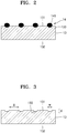
- FIG. 2 is a magnified view of a portion of the gas diffusion layer 14 of FIG. 1 .
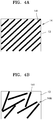
- FIG. 3 is a cross-sectional view of the positive electrode layer 13 of FIG. 2 , not including the gas diffusion layer 14.
- FIG. 4A is a plan view of an embodiment of a gas diffusion layer 14, and
- FIG. 4B is a plan view of an embodiment of a gas diffusion layer 14A.
- the metal-air battery 1 may have a two-dimensional ("2D") planar structure.
- the metal-air battery 1 may be obtained by sequentially depositing a negative electrode metal layer 11, an electrolyte layer 12, a positive electrode layer 13, and the gas diffusion layer 14 for metal-air batteries (hereinafter, referred to as the gas diffusion layer 14).
- the metal-air battery 1 may further include an outer casing (not shown) that surrounds a portion of the metal-air battery 1 except for an upper surface of the gas diffusion layer 14.
- the negative electrode metal layer 11 functions to absorb/release metal ions, and may include, for example, lithium (Li), sodium (Na), zinc (Zn), potassium (K), calcium (Ca), magnesium (Mg), iron (Fe), aluminum (Al), an alloy thereof, or a combination thereof.
- the electrolyte layer 12 functions to transmit metal ions to the positive electrode layer 13.
- the electrolyte layer 12 may be referred to as a negative electrode electrolyte layer.
- the electrolyte layer 12 may include an electrolyte that is formed by dissolving a metal salt in a solvent.
- the electrolyte may be typically in a solid phase including a polymer-based electrolyte, an inorganic electrolyte, or a composite electrolyte obtained by mixing the polymer-based electrolyte with the inorganic electrolyte.
- the electrolyte layer 12 may be prepared in a bent form.
- the metal salt may be a lithium salt such as LiN(SO 2 C 2 F 5 ) 2 , LiClO 4 , LiBF 4 , LiPF 6 , LiSbF 6 , LiAsF 6 , LiCF 3 SO 3 , LiN(SO 2 CF 3 ) 2 , LiC(SO 2 CF 3 ) 3 , LiN(SO 3 CF 3 ) 2 , LiC 4 F 9 SO 3 , LiAlCl 4 , lithium bis(trifluoromethanesulfonyl)imide (“LiTFSI”), or a combination thereof.
- LiTFSI lithium bis(trifluoromethanesulfonyl)imide
- Another metal salt such as AlCl 3 , MgCl 2 , NaCl, KCl, NaBr, KBr, CaCl 2 , or a combination thereof may be added to the lithium salt.
- the solvent may be any material as long as it may dissolve the lithium salt and the another metal salt.
- the electrolyte layer 12 may further include a separation layer that prevents transmission of oxygen and has conductivity with respect to the metal ions.
- the separation layer may be a polymer-based separation film that may be bent.
- the separation layer may be formed of a polymer nonwoven fabric, such as a nonwoven fabric of polypropylene or a nonwoven fabric of polyphenylene sulfide, or a porous film of olefin-based resin, such as polyethylene or polypropylene.
- the separation layer and the electrolyte may be formed as separate layers, or the electrolytic layer 12 may be formed as one layer by impregnating pores of a porous separation layer with an electrolyte.
- the electrolytic layer 12 may be formed by impregnating the pores of a porous separation layer with an electrolyte formed by mixing polyethylene oxide ("PEO") with LiTFSI.
- PEO polyethylene oxide
- the positive electrode layer 13 may include an electrolyte for conducting the metal ions, a catalyst for oxidizing/reducing oxygen, a conductive material, and a binder.
- the positive electrode layer 13 may be formed by preparing a positive electrode slurry by mixing the electrolyte, the catalyst, the conductive material, and the binder, adding a solvent, for example, propylene glycol thereto, and coating and drying the positive electrode slurry on the electrolytic layer 12.
- the electrolyte may include the lithium salt or the another metal salt.
- the conductive material may be a porous carbon-based material, a conductive metal material, a conductive organic material, or a combination thereof.
- the carbon-based material may be carbon black, graphite, graphene, activated carbon, carbon fiber, carbon nanotubes, or a combination thereof.
- the conductive metal material may be used in the form of metal powder.
- the catalyst may be platinum (Pt), gold (Au), silver (Ag), or a combination thereof, or may be an oxide of manganese (Mn), nickel (Ni), cobalt (Co), or a combination thereof.
- the binder may be, for example, polytetrafluoroethylene (“PTFE”), polypropylene, polyvinylidene fluoride (“PVDF”), polyethylene, styrene-butadiene rubber, or a combination thereof.
- PTFE polytetrafluoroethylene
- PVDF polyvinylidene fluoride
- polyethylene polyethylene
- styrene-butadiene rubber or a combination thereof.
- the positive electrode layer 13 has a first surface 131 and a second surface 132 opposite the first surface 131.
- the gas diffusion layer 14 is disposed on the first surface 131 of the positive electrode layer 13, and the electrolyte layer 12 is disposed on the second surface 132.
- the gas diffusion layer 14 functions to absorb oxygen from the atmosphere and supply the oxygen to the positive electrode layer 13.
- the gas diffusion layer 14 may have a structure for moving and diffusing external oxygen, e.g., smoothly moving and diffusing external oxygen.
- the gas diffusion layer 14 may have a flow path structure.
- the gas diffusion layer 14 may have conductivity.
- the first thin film layer may include a plurality of carbon fibers 141.
- Each of the plurality of carbon fibers 141 may include carbon as a main component and have a diameter of less than or equal to about 20 micrometers ( ⁇ m).
- each of the carbon fibers 141 may have a diameter of about 5 ⁇ m to about 10 ⁇ m.
- the carbon fibers 141 may be referred to as graphite fibers.
- the carbon fibers 141 may be hollow carbon fibers.
- Each of the carbon fibers 141 may have a length of greater than or equal to about 3 millimeters (mm).
- a length of the plurality of carbon fibers 141 may be less than or equal to about 1,000 mm.
- the length of each of the carbon fibers 141 may be determined based on a length of the positive electrode layer 13 on which the gas diffusion layer 14 is disposed. For example, when the positive electrode layer 13 is long, long carbon fibers 141 may be used, and, when the positive electrode layer 13 is short, short carbon fibers 141 may be used.
- a weight of the gas diffusion layer 14 may be less than or equal to about 19 %, e.g., about 1 % to about 19%, of an overall weight of the metal-air battery 1.
- the gas diffusion layer 14 may include no binders. Since the gas diffusion layer 14 includes no binders, a weight per unit area, of the gas diffusion layer 14 may be reduced. For example, the weight per unit area of the gas diffusion layer 14 may be less than or equal to about 0.5 milligrams per square centimeter (mg/cm 2 ), e.g., about 0.007 mg/cm 2 to about 0.5 mg/cm 2 .
- the gas diffusion layer 14 of the present application includes no binders, when the plurality of carbon fibers 141 are arranged on the first surface 131 of the positive electrode layer 13 without any special actions, the plurality of carbon fibers 141 may not be fixed to the positive electrode layer 13 and may become scattered or move during the manufacture of the gas diffusion layer 14.
- respective portions of the plurality of carbon fibers 141 may be inserted into the positive electrode layer 13 such that the plurality of carbon fibers 141 may be fixed to the positive electrode layer 13.
- the positive electrode layer 13 may have insertion grooves 133 into which the respective portions of the carbon fibers 141 are inserted. Due to this insertion of the respective portions of the carbon fibers 141 of the gas diffusion layer 14 into the insertion grooves 133 of the positive electrode layer 13, the gas diffusion layer 14 may be fixed to the positive electrode layer 13.
- the insertion grooves 133 of the positive electrode layer 13 may have depths, widths, lengths, and gaps that enable the carbon fibers 141 of the gas diffusion layer 14 to be fixed to the positive electrode layer 13 and also enable oxygen to be sufficiently supplied and diffused.
- an average depth d of the insertion grooves 133 may be about 20 % to about 60 % of a diameter of a carbon fiber of the plurality of carbon fibers 141 or each of the carbon fibers 141.
- each of the insertion grooves 133 may have an average depth d of greater than or equal to about 1.4 ⁇ m.
- an average width w of the insertion grooves 133 may be about 80 % to about 100 % of the diameter of a carbon fiber of the plurality of carbon fibers 141 or each of the carbon fibers 141.
- An average length of each of the insertion grooves 133 may be greater than or equal to about 3 mm.
- An average gap g between adjacent insertion grooves of the plurality of insertion grooves 133 may be about 30 ⁇ m to about 1,000 ⁇ m.
- the gas diffusion layer 14 may include a first space occupied by the carbon fibers 141, and a second space in which no carbon fibers 141 are arranged and oxygen gas is movable and diffusible. A ratio of the second space to the gas diffusion layer 14 may be about 80 % to about 99 %.
- the gas diffusion layer 14 may have a single layer structure.
- the plurality of carbon fibers 141 may be arranged on the positive electrode layer 13 to form a single layer.
- the plurality of carbon fibers 141 extend in a uniform direction and may be spaced apart from each other.
- the arrangement of the plurality of carbon fibers 141 is not limited thereto, and the plurality of carbon fibers 141 may be arranged in various manners.
- the plurality of carbon fibers 141 of the gas diffusion layer 14A extend in various directions and may be arranged to be at least partially spaced apart from each other.
- the plurality of carbon fibers 141 are inserted into the insertion grooves 133 of the positive electrode layer 13 and fixed to the positive electrode layer 13, and thus the weight per unit area may be reduced to less than or equal to about 0.5 mg/cm 2 , e.g., about 0.007 mg/cm 2 to about 0.5 mg/cm 2 , and an energy density of the metal-air battery 1 may be increased.
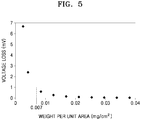
- FIG. 5 is a graph showing a voltage loss versus a weight per unit area of the gas diffusion layer 14.
- the gas diffusion layer 14 may have a weight per unit area of greater than or equal to about 0.007 mg/cm 2 so that a voltage loss due to a resistance in ohms is less than or equal to about 1 millivolt (mV).
- FIG. 6 is a cross-sectional view of an embodiment of a metal-air battery 1B.
- FIG. 7 is a magnified view of a portion of the gas diffusion layer 14B of FIG. 6 .
- FIG. 8A is a plan view of an embodiment of a diffusion layer 14B, and
- FIG. 8B is a plan view of an embodiment of a gas diffusion layer 14C.
- the metal-air battery 1B may include the negative electrode metal layer 11, the electrolyte layer 12, the positive electrode layer 13, and the gas diffusion layer 14B.
- the same component as that in the previous embodiments uses the same reference numeral, and a redundant description thereof will be omitted here.
- the gas diffusion layer 14B has a two-layer structure, and carbon fiber layers 140 and 150 may include a plurality of carbon fibers 141 and a plurality of carbon fibers 151, respectively. Each of the carbon fiber layers 140 and 150 include no binders. In the gas diffusion layer 14B having a two-layer structure, the plurality of carbon fibers 141 and 151 may be arranged in a lattice shape.
- the gas diffusion layer 14B may include a first carbon fiber layer 140 in which respective portions of the plurality of carbon fibers 141 are inserted into the insertion grooves 133 of the first surface 131, and a second carbon fiber layer 150 in which the plurality of carbon fibers 151 extend on the first carbon fiber layer 140 in a direction intersecting with a direction in which each of the carbon fibers 141 of the first carbon fiber layer 140 extends.
- the gas diffusion layer 14B may include the carbon fiber layers 140 and 150 of which the plurality of carbon fibers 141 and the plurality of carbon fibers 151 are arranged in respective uniform directions.
- the gas diffusion layer 14C may include carbon fiber layers 140 and 150 of which the plurality of carbon fibers 141 and 151 are arranged in various directions.
- the carbon fibers 151 of the second carbon fiber layer 150 are spaced apart from the positive electrode layer 13 in FIG. 7 , embodiments are not limited thereto.
- respective portions of the carbon fibers 151 of the second carbon fiber layer 150 may be arranged on the carbon fibers 141 of the first carbon fiber layer 140 and are thus not inserted into the positive electrode layer 13, whereas other portions of the carbon fibers 151 of the second carbon fiber layer 150 may be inserted into portions of the positive electrode layer 13 that is exposed and between the carbon fibers 141 of the first carbon fiber layer 140, e.g., portions of the positive electrode layer 13 not covered by the carbon fibers 141 of the first carbon fiber layer 140.
- Each of the gas diffusion layers 14B and 14C may have a layer structure of two or less layers. If each of the gas diffusion layers 14B and 14C has a layer structure of three or more layers, because there are no binders for fixing the carbon fibers 141 and 151 to each other, carbon fibers 141 and 151 forming three or more layers are not inserted into the positive electrode layer 13, and thus may not be fixed thereto. On the other hand, if each of the gas diffusion layers 14B and 14C has a layer structure of two or less layers, even when there are no binders for fixing the carbon fibers 141 and 151 to each other, carbon fibers 141 and 151 forming two or less layers may be inserted into the positive electrode layer 13 and thus may be supported thereby.
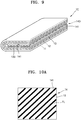
- FIG. 9 is a perspective view of an embodiment of a metal-air battery 1C.
- FIG. 10A is a plan view of an embodiment of a gas diffusion layer 14
- FIG. 10B is a plan view of an embodiment of a gas diffusion layer 14C
- FIG. 10C is a plan view of an embodiment of a gas diffusion layer 14E.
- the metal-air battery 1C may include the negative electrode metal layer 11, the electrolyte layer 12, the positive electrode layer 13, and a gas diffusion layer 14D.
- the same component as that in the previous embodiments uses the same reference numeral, and a redundant description thereof will be omitted here.
- the metal-air battery 1C may have a three-dimensional (3D) shape.
- the negative electrode metal layer 11, the electrolyte layer 12, and the positive electrode layer 13 may be bent.
- the gas diffusion layer 14 may have a one-layer structure in which the plurality of carbon fibers 141 are arranged on the positive electrode layer 13. Respective portions of the carbon fibers 141 may be inserted into the insertion grooves 133 of the positive electrode layer 13.
- the gas diffusion layer 14 is bent along a bending line FL to thereby form the gas diffusion layer 14D of a structure in which both ends of the gas diffusion layer 14D face each other as shown in FIG. 9 .
- the bent gas diffusion layer 14D may have a two-layer structure.
- the gas diffusion layer 14C may include the first carbon fiber layer 140, on which the plurality of carbon fibers 141 are arranged on the positive electrode layer 13, and the second carbon fiber layer 150, on which the plurality of carbon fibers 151 are arranged on the first carbon fiber layer 140.
- the carbon fibers 141 of the first carbon fiber layer 140 may intersect with the carbon fibers 151 of the second carbon fiber layer 150.
- the gas diffusion layer 14C is bent along the bending line FL to thereby form the gas diffusion layer 14D of a structure in which both ends of the gas diffusion layer 14D face each other.
- the bent gas diffusion layer 14D may have a layer structure of four or less layers.
- the gas diffusion layer 14E may be disposed on a portion of the positive electrode layer 13.
- the negative electrode metal layer 11, the electrolyte layer 12, and the positive electrode layer 13 are bent over the gas diffusion layer 14E such that the positive electrode layer 13 contacts three surfaces of the gas diffusion layer 14E, and one surface of the gas diffusion layer 14E may be exposed.
- the gas diffusion layer 14E may have a layer structure of two or less layers.
- a structure in which a single gas diffusion layer 14D is included and the negative electrode metal layer 11, the electrolyte layer 12, and the positive electrode layer 13 are bent once has been illustrated as the metal-air battery 1C having a 3D shape.
- the metal-air battery 1C having a 3D shape is not limited thereto and may be variously modified.
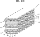
- a metal-air battery 1D may include a plurality of gas diffusion layers 14D, and may have a structure in which the negative electrode metal layer 11, the electrolyte layer 12, and the positive electrode layer 13 are bent multiple times.
- FIG. 11A a metal-air battery 1D may include a plurality of gas diffusion layers 14D, and may have a structure in which the negative electrode metal layer 11, the electrolyte layer 12, and the positive electrode layer 13 are bent multiple times.
- a metal-air battery 1E may have a structure in which a plurality of battery cells 10 are arranged vertically, each battery cell 10 has a single gas diffusion layer 14D, and the negative electrode metal layer 11, the electrolyte layer 12, and the positive electrode layer 13 are bent once for each battery cell 10.
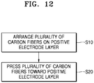
- FIG. 12 is a flowchart of a method of manufacturing the metal-air battery 1, according to an embodiment.
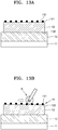
- FIGS. 13A and 13B are cross-sectional views of an embodiment of a method of manufacturing the metal-air battery 1.
- a plurality of carbon fibers 141 are arranged on the first surface 131 of the positive electrode layer 13, in operation S10.
- the plurality of carbon fibers 141 may be sprayed onto the first surface 131 of the positive electrode layer 13.
- the plurality of carbon fibers 141 may be arranged such that the average gap, e.g., distance, between adjacent carbon fibers of the plurality of carbon fibers 141 is about 30 ⁇ m to about 1,000 ⁇ m.
- Each of the plurality of carbon fibers 141 may include carbon as a main component, and have a diameter of less than or equal to about 20 ⁇ m.
- each carbon fiber 141 may have a diameter of about 5 ⁇ m to about 10 ⁇ m.
- the carbon fibers 141 may be referred to as graphite fibers.
- the carbon fibers 141 may be hollow carbon fibers.
- Each of the carbon fibers 141 may have a length of greater than or equal to about 3 mm.
- a length of the plurality of carbon fibers 141 may be less than or equal to about 1,000 mm.
- the length of each of the carbon fibers 141 may be determined based on a length of the positive electrode layer 13. For example, when the positive electrode layer 13 is long, long carbon fibers 141 may be used, and, when the positive electrode layer 13 is short, short carbon fibers 141 may be used.
- the plurality of carbon fibers 141 when the plurality of carbon fibers 141 are arranged on one surface of the positive electrode layer 13, the plurality of carbon fibers 141 are pressed toward the positive electrode layer 13, in operation S20. Due to the pressing, respective portions of the plurality of carbon fibers 141 may be inserted into the first surface 131 of the positive electrode layer 13. Accordingly, a plurality of insertion grooves 133 into which the respective portions of the carbon fibers 141 have been inserted may be formed on the positive electrode layer 13.
- the carbon fibers 141 arranged on one surface of the positive electrode layer 13 may be pressed by a rotatable roller R and thus may be stuck into the positive electrode layer 13.
- the plurality of carbon fibers 141 may be sequentially pressed by rotating and moving the roller R.
- the plurality of carbon fibers 141 of the gas diffusion layer 14 may be pressed such that the carbon fibers 141 are fixable to the positive electrode layer 13.
- the carbon fibers 141 may be pressed toward the positive electrode layer 13 such that the average depth of the insertion grooves 133 is about 20 % to about 60 % of the diameter of a carbon fiber of the plurality of carbon fibers 141 or each of the carbon fibers 141.
- the carbon fibers 141 may be pressed toward the positive electrode layer 13 such that the average width of the insertion grooves 133 is about 80 % to about 100 % of the diameter of a carbon fiber of the plurality of carbon fibers 141 or each of the carbon fibers 141.
- the plurality of carbon fibers 141 are arranged such that respective portions thereof are inserted into the positive electrode layer 13, and thus the gas diffusion layer 14 supported by one surface of the positive electrode layer 13 may be formed.
- the weight per unit area of the gas diffusion layer 14 may be minimized.
- the weight per unit area of the gas diffusion layer 14 may be less than or equal to about 0.5 mg/cm 2 .
- the weight per unit area of the gas diffusion layer 14 may be greater than or equal to about 0.007 mg/cm 2 .
- a method of fixing the gas diffusion layer 14 onto the positive electrode layer 13 has been described by focusing on the method of manufacturing the metal-air battery 1 having a 2D planar structure.
- the fixing method is not limited thereto, and may be applied to methods of manufacturing the metal-air batteries 1B, 1C, 1D, and 1E having various structures.
- the 3D metal-air batteries 1C, 1D, and 1E each having a bent structure may be manufactured by bending the gas diffusion layer 14 supported by the positive electrode layer 13 due to pressing of the plurality of carbon fibers 141, the positive electrode layer 13, the electrolyte layer 12, and the negative electrode metal layer 11.
- FIG. 14 is an electron microscope view of the positive electrode layer 13 manufactured in the method of manufacturing the metal-air battery 1.
- the insertion grooves 133 are formed in a surface of the positive electrode layer 13.
- the insertion grooves 133 may be distinguished from fine grooves generated during the manufacture of the positive electrode layer 13.
- a depth of each of the insertion groove 133 may be greater than or equal to about 1.4 ⁇ m. According to an embodiment, the depth of each of the insertion groove 133 may be greater than or equal to about 4 ⁇ m.
- Comparative Example 1 Manufacture of comparative lithium-air battery
- Carbon nanotubes, a PTFE binder, and a positive electrode electrolyte solution were weighed at a certain weight ratio, for example 1:0.2:2 and then mechanically kneaded, and a result of the kneading was manufactured to have a certain thickness, for example 30 urn by a roll press and then dried for two hours in an oven of 80°C, thereby manufacturing a rectangular positive electrode layer.
- a weight per unit area of the positive electrode layer was 2.7 milligrams per square centimeter (mg/cm 2 ).
- a separation layer was coated with a poly(diallyldimethylammonium-bis (trifluoromethanesulfonyl)imide) (“PIL”) solution including electrolyte, for example LiTFSI and then vacuum-dried (at 60°C and for 6 hours) such that a solvent is removed from the separation layer, to thereby obtaining a solid electrolyte layer.
- PIL poly(diallyldimethylammonium-bis (trifluoromethanesulfonyl)imide)
- electrolyte for example LiTFSI
- a weight per unit area of the electrolyte layer was 2.7 mg/cm 2 .
- the electrolyte layer was disposed on one surface of the positive electrode layer, and a lithium metal as a negative electrode metal layer was disposed on the surface of the electrolyte layer opposite to the positive electrode layer.
- Comparative Example 2 Manufacture of comparative lithium-air battery
- a lithium-air battery according to Comparative Example 2 was manufactured the same as the lithium-air battery according to Comparative Example 1, except that a gas diffusion layer was disposed within a bent positive electrode layer.
- the lithium-air battery according to Comparative Example 2 was manufactured by disposing a gas diffusion layer on a positive electrode layer and then bending the positive electrode layer, an electrolyte layer, and a negative electrode metal layer as shown in FIG. 9 such that the positive electrode layer surrounds at least three surfaces of the gas diffusion layer. At this time, a carbon paper having a weight per unit area of 4.2 mg/cm 2 was used as the gas diffusion layer.
- the positive electrode layer was manufactured using the same method as that used in Comparative Example 1.
- the electrolyte layer was manufactured using the same method as that used in Comparative Example 1.
- a plurality of carbon fibers (graphite fibers by Fibre Glast) having a length of 0.25 inches and a diameter of 7 ⁇ m are arranged on the positive electrode layer.
- the plurality of carbon fibers arranged on the positive electrode layer are pressed with a certain pressure.
- the plurality of carbon fibers are inserted into and fixed to insertion grooves of the positive electrode layer.
- the gas diffusion layer is fixed to the positive electrode layer without using binders, and has a weight per unit area of 0.2 mg/cm 2 .
- the lithium-air battery according to Embodiment 1 was manufactured by disposing the gas diffusion layer on the positive electrode layer and then bending the gas diffusion layer, the positive electrode layer, the electrolyte layer, and the negative electrode metal layer as shown in FIGS. 9 and 10A .
- the lithium-air battery according to Embodiment 2 was manufactured the same as the lithium-air battery according to Embodiment 1, except for a weight per unit area of a gas diffusion layer.
- the gas diffusion layer is fixed to a positive electrode layer without using binders, and has a weight per unit area of 0.05 mg/cm 2 .
- the lithium-air battery according to Embodiment 3 was manufactured the same as the lithium-air battery according to Embodiment 1, except for a weight per unit area of a gas diffusion layer.
- the gas diffusion layer is fixed to a positive electrode layer without using binders, and has a weight per unit area of 0.03 mg/cm 2 .
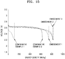
- Discharge capacities of the lithium-air batteries manufactured according to Embodiments 1 to 3 and Comparative Examples 1 to 2 were measured at 80°C under a 1 atmosphere (atm) oxygen atmosphere, and a result of the measurement was shown in Table 1 and FIG. 15 .
- each of the lithium-air batteries has a once-bent structure in which a positive electrode is disposed on an upper portion and a lower portion of a gas diffusion layer
- a weight per unit area of the gas diffusion layer according to Comparative Example 2 was calculated by respectively allocating halves of the weight per unit area to an upper positive electrode and a lower positive electrode.
- Table 1 Shape of gas diffusion layer Weight per unit area (mg/cm 2 ) Energy density (Wh/kg) Comparative Example 1 none 0 112 Comparative Example 2 Carbon paper 2.1 632 Embodiment 1 Carbon fibers (no binders) 0.2 744 Embodiment 2 Carbon fibers (no binders) 0.05 820 Embodiment 3 Carbon fibers (no binders) 0.03 827
- the lithium-air battery having a gas diffusion layer according to Comparative Example 2 has an increased energy density but has an increased weight per unit area of 2.1 mg/cm 2 due to the presence of the gas diffusion layer.
- the lithium-air battery according to Embodiment 1 uses carbon fibers without binders as a gas diffusion layer.
- the weight per unit area of the gas diffusion layer may be reduced to less than or equal to about 1/10 of the weight per unit area of the gas diffusion layer according to Comparative Example 2, and the energy density may be increased.
- the weight per unit area of the gas diffusion layer may be less than the weight per unit area of the gas diffusion layer of Embodiment 1 and the energy density may be greater than the energy density of Embodiment 1.
- a metal-air battery including the gas diffusion layer As described above, according to a gas diffusion layer for metal-air batteries, a metal-air battery including the gas diffusion layer, and a method of manufacturing the metal-air battery, according to an embodiment, respective portions of carbon fibers are inserted into and fixed to a positive electrode layer in order to include no binders. Therefore, the weight per unit area of the gas diffusion layer may be reduced, and accordingly, the energy density of the metal-air battery may be increased.
Landscapes
- Chemical & Material Sciences (AREA)
- Chemical Kinetics & Catalysis (AREA)
- Electrochemistry (AREA)
- General Chemical & Material Sciences (AREA)
- Engineering & Computer Science (AREA)
- Manufacturing & Machinery (AREA)
- Materials Engineering (AREA)
- Sustainable Energy (AREA)
- Sustainable Development (AREA)
- Life Sciences & Earth Sciences (AREA)
- Composite Materials (AREA)
- Inert Electrodes (AREA)
- Hybrid Cells (AREA)
Applications Claiming Priority (1)
| Application Number | Priority Date | Filing Date | Title |
|---|---|---|---|
| KR1020170094966A KR102452946B1 (ko) | 2017-07-26 | 2017-07-26 | 금속 공기 전지용 기체 확산층, 이를 포함하는 금속 공기 전지 및 그 제조방법 |
Publications (2)
| Publication Number | Publication Date |
|---|---|
| EP3435458A1 true EP3435458A1 (fr) | 2019-01-30 |
| EP3435458B1 EP3435458B1 (fr) | 2023-12-13 |
Family
ID=62563070
Family Applications (1)
| Application Number | Title | Priority Date | Filing Date |
|---|---|---|---|
| EP18176472.1A Active EP3435458B1 (fr) | 2017-07-26 | 2018-06-07 | Batterie métal-air comprenant une couche de diffusion de gaz et procédé de fabrication de la batterie métal-air |
Country Status (4)
| Country | Link |
|---|---|
| US (1) | US10707495B2 (fr) |
| EP (1) | EP3435458B1 (fr) |
| KR (1) | KR102452946B1 (fr) |
| CN (1) | CN109309271B (fr) |
Cited By (1)
| Publication number | Priority date | Publication date | Assignee | Title |
|---|---|---|---|---|
| CN112886101A (zh) * | 2019-11-29 | 2021-06-01 | 三星电子株式会社 | 金属-空气电池和制造金属-空气电池的方法 |
Families Citing this family (12)
| Publication number | Priority date | Publication date | Assignee | Title |
|---|---|---|---|---|
| BR112019008041A2 (pt) | 2016-10-21 | 2019-07-02 | Nantenergy Inc | elétrodo de combustível corrugado |
| WO2019133702A1 (fr) | 2017-12-29 | 2019-07-04 | Staq Energy, Inc. | Batteries secondaires alcalines scellées à longue durée de vie |
| KR102526758B1 (ko) | 2018-01-09 | 2023-04-27 | 삼성전자주식회사 | 복합막, 이를 포함한 음극 구조체 및 리튬전지, 및 복합막 제조방법 |
| MA53343A (fr) | 2018-07-27 | 2022-03-23 | Form Energy Inc | Électrodes négatives pour cellules électrochimiques |
| US12294086B2 (en) | 2019-07-26 | 2025-05-06 | Form Energy, Inc. | Low cost metal electrodes |
| KR20210155878A (ko) * | 2020-06-17 | 2021-12-24 | 현대자동차주식회사 | 리튬공기전지의 양극재료 및 이를 이용한 양극 제조방법 |
| DE112021003695T5 (de) | 2020-07-29 | 2023-06-29 | Eaton Intelligent Power Limited | Verbindersystem einschliesslich eines verriegelungssystems |
| WO2022040636A1 (fr) | 2020-08-21 | 2022-02-24 | Royal Precision Products, Llc | Système de connecteur électrique à haute intensité admissible |
| KR20240141800A (ko) * | 2022-01-28 | 2024-09-27 | 폼 에너지 인코퍼레이티드 | 양면 밀봉형 기체 확산 전극 |
| KR20240149932A (ko) | 2022-02-09 | 2024-10-15 | 이턴 인텔리전트 파워 리미티드 | 전력 분배 시스템에서 여러 부품을 연결하기 위한 스플라이스 블록 시스템 |
| CN114953635B (zh) * | 2022-05-30 | 2023-09-15 | 安徽天富环保科技材料有限公司 | 一种用于新能源电池气体扩散的活性碳纤维布 |
| DE112024002411T5 (de) | 2023-06-05 | 2026-03-19 | Eaton Intelligent Power Limited | Elektrisches verbindungssystem mit einer steckeranordnung mit einer druckbegrenzungseinrichtung |
Citations (4)
| Publication number | Priority date | Publication date | Assignee | Title |
|---|---|---|---|---|
| EP2278655A1 (fr) * | 2009-03-06 | 2011-01-26 | Toyota Jidosha Kabushiki Kaisha | Electrode à air et batterie à air non aqueuse |
| US20160336602A1 (en) * | 2015-05-15 | 2016-11-17 | Samsung Electronics Co., Ltd. | Metal air battery and gas diffusion layer thereof |
| US20170054189A1 (en) * | 2015-08-17 | 2017-02-23 | Samsung Electronics Co., Ltd. | Metal air battery and gas diffusion layer equipped therein |
| EP3316366A1 (fr) * | 2016-01-20 | 2018-05-02 | LG Chem, Ltd. | Électrode positive de batterie au lithium-air ayant un film de prévention de réaction secondaire sur lequel un catalyseur métallique est partiellement introduit, batterie au lithium-air la comprenant et son procédé de fabrication |
Family Cites Families (15)
| Publication number | Priority date | Publication date | Assignee | Title |
|---|---|---|---|---|
| US6500319B2 (en) * | 2001-04-05 | 2002-12-31 | Giner Electrochemical Systems, Llc | Proton exchange membrane (PEM) electrochemical cell having an integral, electrically-conductive, compression pad |
| US8182659B2 (en) * | 2001-04-05 | 2012-05-22 | Giner Electrochemical Systems, Llc | Proton exchange membrane (PEM) electrochemical cell having an integral, electrically-conductive, resiliently compressible, porous pad |
| US8293685B2 (en) | 2007-07-26 | 2012-10-23 | The Regents Of The University Of California | Methods for enhancing bacterial cell display of proteins and peptides |
| KR100920115B1 (ko) | 2007-11-08 | 2009-10-01 | 금오공과대학교 산학협력단 | Htts로 코팅한 가스확산층과 그의 제조 방법 |
| JP2011096492A (ja) * | 2009-10-29 | 2011-05-12 | Sony Corp | リチウム空気電池 |
| US20110253699A1 (en) * | 2010-04-16 | 2011-10-20 | Morin Philip K | Portable food warmer with carbon fiber heating element |
| US8274019B2 (en) * | 2010-04-16 | 2012-09-25 | Carbon Fibers Heating Technologies, LLC | High temperature connector and method for manufacturing |
| US10047446B2 (en) * | 2010-07-04 | 2018-08-14 | Dioxide Materials, Inc. | Method and system for electrochemical production of formic acid from carbon dioxide |
| JP5421227B2 (ja) * | 2010-07-05 | 2014-02-19 | 株式会社日本自動車部品総合研究所 | 燃料電池のガス拡散層の製造方法、製造装置および燃料電池 |
| KR101851317B1 (ko) | 2011-07-26 | 2018-05-31 | 삼성전자주식회사 | 다공성 탄소계 복합재료, 이를 포함하는 양극 및 리튬공기전지, 및 이의 제조방법 |
| US8979574B2 (en) | 2012-08-15 | 2015-03-17 | Tyco Electronics Corporation | Modular plug |
| US8714994B2 (en) | 2012-08-15 | 2014-05-06 | Tyco Electronics Corporation | Modular plug for power applications |
| KR101945585B1 (ko) | 2012-12-05 | 2019-02-07 | 도레이 카부시키가이샤 | 탄소 섬유 부직포 및 이를 이용한 고체 고분자형 연료 전지의 가스 확산 전극, 고체 고분자형 연료 전지, 탄소 섬유 부직포의 제조 방법, 및 복합 시트 |
| KR101646397B1 (ko) | 2014-12-03 | 2016-08-05 | 현대자동차주식회사 | 리튬공기전지용 양극의 제조방법 |
| KR20170020162A (ko) | 2015-08-14 | 2017-02-22 | 주식회사 엘지화학 | 리튬 공기 전지 및 이의 제조 방법 |
-
2017
- 2017-07-26 KR KR1020170094966A patent/KR102452946B1/ko active Active
-
2018
- 2018-04-09 US US15/947,997 patent/US10707495B2/en active Active
- 2018-04-11 CN CN201810319729.3A patent/CN109309271B/zh active Active
- 2018-06-07 EP EP18176472.1A patent/EP3435458B1/fr active Active
Patent Citations (4)
| Publication number | Priority date | Publication date | Assignee | Title |
|---|---|---|---|---|
| EP2278655A1 (fr) * | 2009-03-06 | 2011-01-26 | Toyota Jidosha Kabushiki Kaisha | Electrode à air et batterie à air non aqueuse |
| US20160336602A1 (en) * | 2015-05-15 | 2016-11-17 | Samsung Electronics Co., Ltd. | Metal air battery and gas diffusion layer thereof |
| US20170054189A1 (en) * | 2015-08-17 | 2017-02-23 | Samsung Electronics Co., Ltd. | Metal air battery and gas diffusion layer equipped therein |
| EP3316366A1 (fr) * | 2016-01-20 | 2018-05-02 | LG Chem, Ltd. | Électrode positive de batterie au lithium-air ayant un film de prévention de réaction secondaire sur lequel un catalyseur métallique est partiellement introduit, batterie au lithium-air la comprenant et son procédé de fabrication |
Cited By (1)
| Publication number | Priority date | Publication date | Assignee | Title |
|---|---|---|---|---|
| CN112886101A (zh) * | 2019-11-29 | 2021-06-01 | 三星电子株式会社 | 金属-空气电池和制造金属-空气电池的方法 |
Also Published As
| Publication number | Publication date |
|---|---|
| CN109309271A (zh) | 2019-02-05 |
| US20190036127A1 (en) | 2019-01-31 |
| US10707495B2 (en) | 2020-07-07 |
| CN109309271B (zh) | 2024-03-12 |
| KR20190012064A (ko) | 2019-02-08 |
| KR102452946B1 (ko) | 2022-10-11 |
| EP3435458B1 (fr) | 2023-12-13 |
Similar Documents
| Publication | Publication Date | Title |
|---|---|---|
| EP3435458B1 (fr) | Batterie métal-air comprenant une couche de diffusion de gaz et procédé de fabrication de la batterie métal-air | |
| KR102420022B1 (ko) | 금속공기전지용 양극 및 이를 포함하는 금속공기전지 | |
| KR102654869B1 (ko) | 복합 전해질막, 이를 포함하는 전기 화학 전지 및 복합 전해질막 제조방법 | |
| KR101249133B1 (ko) | 2극 장치 | |
| EP3157084B1 (fr) | Cathode composite, ensemble cathode-membrane, cellule électrochimique contenant l'ensemble cathode-membrane et procédé de préparation de l'ensemble cathode-membrane | |
| DE102014116162A1 (de) | Multifunktionaler Batterieseparator | |
| US11276861B2 (en) | Positive electrode for air battery | |
| US9786932B2 (en) | Metal-air battery | |
| US10020552B2 (en) | Metal air battery and cathode current collector included therein | |
| US9972876B2 (en) | Metal air battery and gas diffusion layer equipped therein | |
| EP3712996B1 (fr) | Batterie à air et électrode positive pour batterie à air | |
| US10263306B2 (en) | Metal air battery and gas diffusion layer thereof | |
| US10381697B2 (en) | Metal-air battery including cathode with air path | |
| KR102452954B1 (ko) | 금속공기전지용 양극 및 이를 포함하는 금속공기전지 | |
| KR20250158853A (ko) | 리튬 이차 전지용 분리막 및 이를 포함하는 리튬 이차 전지 |
Legal Events
| Date | Code | Title | Description |
|---|---|---|---|
| PUAI | Public reference made under article 153(3) epc to a published international application that has entered the european phase |
Free format text: ORIGINAL CODE: 0009012 |
|
| STAA | Information on the status of an ep patent application or granted ep patent |
Free format text: STATUS: THE APPLICATION HAS BEEN PUBLISHED |
|
| AK | Designated contracting states |
Kind code of ref document: A1 Designated state(s): AL AT BE BG CH CY CZ DE DK EE ES FI FR GB GR HR HU IE IS IT LI LT LU LV MC MK MT NL NO PL PT RO RS SE SI SK SM TR |
|
| AX | Request for extension of the european patent |
Extension state: BA ME |
|
| STAA | Information on the status of an ep patent application or granted ep patent |
Free format text: STATUS: REQUEST FOR EXAMINATION WAS MADE |
|
| 17P | Request for examination filed |
Effective date: 20190730 |
|
| RBV | Designated contracting states (corrected) |
Designated state(s): AL AT BE BG CH CY CZ DE DK EE ES FI FR GB GR HR HU IE IS IT LI LT LU LV MC MK MT NL NO PL PT RO RS SE SI SK SM TR |
|
| STAA | Information on the status of an ep patent application or granted ep patent |
Free format text: STATUS: EXAMINATION IS IN PROGRESS |
|
| 17Q | First examination report despatched |
Effective date: 20230222 |
|
| GRAP | Despatch of communication of intention to grant a patent |
Free format text: ORIGINAL CODE: EPIDOSNIGR1 |
|
| STAA | Information on the status of an ep patent application or granted ep patent |
Free format text: STATUS: GRANT OF PATENT IS INTENDED |
|
| P01 | Opt-out of the competence of the unified patent court (upc) registered |
Effective date: 20230520 |
|
| INTG | Intention to grant announced |
Effective date: 20230626 |
|
| GRAS | Grant fee paid |
Free format text: ORIGINAL CODE: EPIDOSNIGR3 |
|
| GRAA | (expected) grant |
Free format text: ORIGINAL CODE: 0009210 |
|
| STAA | Information on the status of an ep patent application or granted ep patent |
Free format text: STATUS: THE PATENT HAS BEEN GRANTED |
|
| AK | Designated contracting states |
Kind code of ref document: B1 Designated state(s): AL AT BE BG CH CY CZ DE DK EE ES FI FR GB GR HR HU IE IS IT LI LT LU LV MC MK MT NL NO PL PT RO RS SE SI SK SM TR |
|
| REG | Reference to a national code |
Ref country code: GB Ref legal event code: FG4D |
|
| REG | Reference to a national code |
Ref country code: CH Ref legal event code: EP |
|
| REG | Reference to a national code |
Ref country code: DE Ref legal event code: R096 Ref document number: 602018062487 Country of ref document: DE |
|
| REG | Reference to a national code |
Ref country code: IE Ref legal event code: FG4D |
|
| PG25 | Lapsed in a contracting state [announced via postgrant information from national office to epo] |
Ref country code: GR Free format text: LAPSE BECAUSE OF FAILURE TO SUBMIT A TRANSLATION OF THE DESCRIPTION OR TO PAY THE FEE WITHIN THE PRESCRIBED TIME-LIMIT Effective date: 20240314 |
|
| REG | Reference to a national code |
Ref country code: LT Ref legal event code: MG9D |
|
| PG25 | Lapsed in a contracting state [announced via postgrant information from national office to epo] |
Ref country code: LT Free format text: LAPSE BECAUSE OF FAILURE TO SUBMIT A TRANSLATION OF THE DESCRIPTION OR TO PAY THE FEE WITHIN THE PRESCRIBED TIME-LIMIT Effective date: 20231213 |
|
| REG | Reference to a national code |
Ref country code: NL Ref legal event code: MP Effective date: 20231213 |
|
| PG25 | Lapsed in a contracting state [announced via postgrant information from national office to epo] |
Ref country code: ES Free format text: LAPSE BECAUSE OF FAILURE TO SUBMIT A TRANSLATION OF THE DESCRIPTION OR TO PAY THE FEE WITHIN THE PRESCRIBED TIME-LIMIT Effective date: 20231213 |
|
| PG25 | Lapsed in a contracting state [announced via postgrant information from national office to epo] |
Ref country code: LT Free format text: LAPSE BECAUSE OF FAILURE TO SUBMIT A TRANSLATION OF THE DESCRIPTION OR TO PAY THE FEE WITHIN THE PRESCRIBED TIME-LIMIT Effective date: 20231213 Ref country code: GR Free format text: LAPSE BECAUSE OF FAILURE TO SUBMIT A TRANSLATION OF THE DESCRIPTION OR TO PAY THE FEE WITHIN THE PRESCRIBED TIME-LIMIT Effective date: 20240314 Ref country code: ES Free format text: LAPSE BECAUSE OF FAILURE TO SUBMIT A TRANSLATION OF THE DESCRIPTION OR TO PAY THE FEE WITHIN THE PRESCRIBED TIME-LIMIT Effective date: 20231213 Ref country code: BG Free format text: LAPSE BECAUSE OF FAILURE TO SUBMIT A TRANSLATION OF THE DESCRIPTION OR TO PAY THE FEE WITHIN THE PRESCRIBED TIME-LIMIT Effective date: 20240313 |
|
| REG | Reference to a national code |
Ref country code: AT Ref legal event code: MK05 Ref document number: 1641239 Country of ref document: AT Kind code of ref document: T Effective date: 20231213 |
|
| PG25 | Lapsed in a contracting state [announced via postgrant information from national office to epo] |
Ref country code: NL Free format text: LAPSE BECAUSE OF FAILURE TO SUBMIT A TRANSLATION OF THE DESCRIPTION OR TO PAY THE FEE WITHIN THE PRESCRIBED TIME-LIMIT Effective date: 20231213 |
|
| PG25 | Lapsed in a contracting state [announced via postgrant information from national office to epo] |
Ref country code: SE Free format text: LAPSE BECAUSE OF FAILURE TO SUBMIT A TRANSLATION OF THE DESCRIPTION OR TO PAY THE FEE WITHIN THE PRESCRIBED TIME-LIMIT Effective date: 20231213 Ref country code: RS Free format text: LAPSE BECAUSE OF FAILURE TO SUBMIT A TRANSLATION OF THE DESCRIPTION OR TO PAY THE FEE WITHIN THE PRESCRIBED TIME-LIMIT Effective date: 20231213 Ref country code: NO Free format text: LAPSE BECAUSE OF FAILURE TO SUBMIT A TRANSLATION OF THE DESCRIPTION OR TO PAY THE FEE WITHIN THE PRESCRIBED TIME-LIMIT Effective date: 20240313 Ref country code: NL Free format text: LAPSE BECAUSE OF FAILURE TO SUBMIT A TRANSLATION OF THE DESCRIPTION OR TO PAY THE FEE WITHIN THE PRESCRIBED TIME-LIMIT Effective date: 20231213 Ref country code: LV Free format text: LAPSE BECAUSE OF FAILURE TO SUBMIT A TRANSLATION OF THE DESCRIPTION OR TO PAY THE FEE WITHIN THE PRESCRIBED TIME-LIMIT Effective date: 20231213 Ref country code: HR Free format text: LAPSE BECAUSE OF FAILURE TO SUBMIT A TRANSLATION OF THE DESCRIPTION OR TO PAY THE FEE WITHIN THE PRESCRIBED TIME-LIMIT Effective date: 20231213 |
|
| PG25 | Lapsed in a contracting state [announced via postgrant information from national office to epo] |
Ref country code: IS Free format text: LAPSE BECAUSE OF FAILURE TO SUBMIT A TRANSLATION OF THE DESCRIPTION OR TO PAY THE FEE WITHIN THE PRESCRIBED TIME-LIMIT Effective date: 20240413 |
|
| PG25 | Lapsed in a contracting state [announced via postgrant information from national office to epo] |
Ref country code: AT Free format text: LAPSE BECAUSE OF FAILURE TO SUBMIT A TRANSLATION OF THE DESCRIPTION OR TO PAY THE FEE WITHIN THE PRESCRIBED TIME-LIMIT Effective date: 20231213 Ref country code: CZ Free format text: LAPSE BECAUSE OF FAILURE TO SUBMIT A TRANSLATION OF THE DESCRIPTION OR TO PAY THE FEE WITHIN THE PRESCRIBED TIME-LIMIT Effective date: 20231213 |
|
| PG25 | Lapsed in a contracting state [announced via postgrant information from national office to epo] |
Ref country code: SK Free format text: LAPSE BECAUSE OF FAILURE TO SUBMIT A TRANSLATION OF THE DESCRIPTION OR TO PAY THE FEE WITHIN THE PRESCRIBED TIME-LIMIT Effective date: 20231213 |
|
| PG25 | Lapsed in a contracting state [announced via postgrant information from national office to epo] |
Ref country code: SM Free format text: LAPSE BECAUSE OF FAILURE TO SUBMIT A TRANSLATION OF THE DESCRIPTION OR TO PAY THE FEE WITHIN THE PRESCRIBED TIME-LIMIT Effective date: 20231213 Ref country code: SK Free format text: LAPSE BECAUSE OF FAILURE TO SUBMIT A TRANSLATION OF THE DESCRIPTION OR TO PAY THE FEE WITHIN THE PRESCRIBED TIME-LIMIT Effective date: 20231213 Ref country code: RO Free format text: LAPSE BECAUSE OF FAILURE TO SUBMIT A TRANSLATION OF THE DESCRIPTION OR TO PAY THE FEE WITHIN THE PRESCRIBED TIME-LIMIT Effective date: 20231213 Ref country code: IT Free format text: LAPSE BECAUSE OF FAILURE TO SUBMIT A TRANSLATION OF THE DESCRIPTION OR TO PAY THE FEE WITHIN THE PRESCRIBED TIME-LIMIT Effective date: 20231213 Ref country code: IS Free format text: LAPSE BECAUSE OF FAILURE TO SUBMIT A TRANSLATION OF THE DESCRIPTION OR TO PAY THE FEE WITHIN THE PRESCRIBED TIME-LIMIT Effective date: 20240413 Ref country code: EE Free format text: LAPSE BECAUSE OF FAILURE TO SUBMIT A TRANSLATION OF THE DESCRIPTION OR TO PAY THE FEE WITHIN THE PRESCRIBED TIME-LIMIT Effective date: 20231213 Ref country code: CZ Free format text: LAPSE BECAUSE OF FAILURE TO SUBMIT A TRANSLATION OF THE DESCRIPTION OR TO PAY THE FEE WITHIN THE PRESCRIBED TIME-LIMIT Effective date: 20231213 Ref country code: AT Free format text: LAPSE BECAUSE OF FAILURE TO SUBMIT A TRANSLATION OF THE DESCRIPTION OR TO PAY THE FEE WITHIN THE PRESCRIBED TIME-LIMIT Effective date: 20231213 |
|
| PG25 | Lapsed in a contracting state [announced via postgrant information from national office to epo] |
Ref country code: PL Free format text: LAPSE BECAUSE OF FAILURE TO SUBMIT A TRANSLATION OF THE DESCRIPTION OR TO PAY THE FEE WITHIN THE PRESCRIBED TIME-LIMIT Effective date: 20231213 Ref country code: PT Free format text: LAPSE BECAUSE OF FAILURE TO SUBMIT A TRANSLATION OF THE DESCRIPTION OR TO PAY THE FEE WITHIN THE PRESCRIBED TIME-LIMIT Effective date: 20240415 |
|
| PG25 | Lapsed in a contracting state [announced via postgrant information from national office to epo] |
Ref country code: PT Free format text: LAPSE BECAUSE OF FAILURE TO SUBMIT A TRANSLATION OF THE DESCRIPTION OR TO PAY THE FEE WITHIN THE PRESCRIBED TIME-LIMIT Effective date: 20240415 Ref country code: PL Free format text: LAPSE BECAUSE OF FAILURE TO SUBMIT A TRANSLATION OF THE DESCRIPTION OR TO PAY THE FEE WITHIN THE PRESCRIBED TIME-LIMIT Effective date: 20231213 |
|
| REG | Reference to a national code |
Ref country code: DE Ref legal event code: R097 Ref document number: 602018062487 Country of ref document: DE |
|
| PG25 | Lapsed in a contracting state [announced via postgrant information from national office to epo] |
Ref country code: DK Free format text: LAPSE BECAUSE OF FAILURE TO SUBMIT A TRANSLATION OF THE DESCRIPTION OR TO PAY THE FEE WITHIN THE PRESCRIBED TIME-LIMIT Effective date: 20231213 |
|
| PLBE | No opposition filed within time limit |
Free format text: ORIGINAL CODE: 0009261 |
|
| STAA | Information on the status of an ep patent application or granted ep patent |
Free format text: STATUS: NO OPPOSITION FILED WITHIN TIME LIMIT |
|
| PG25 | Lapsed in a contracting state [announced via postgrant information from national office to epo] |
Ref country code: SI Free format text: LAPSE BECAUSE OF FAILURE TO SUBMIT A TRANSLATION OF THE DESCRIPTION OR TO PAY THE FEE WITHIN THE PRESCRIBED TIME-LIMIT Effective date: 20231213 |
|
| PG25 | Lapsed in a contracting state [announced via postgrant information from national office to epo] |
Ref country code: SI Free format text: LAPSE BECAUSE OF FAILURE TO SUBMIT A TRANSLATION OF THE DESCRIPTION OR TO PAY THE FEE WITHIN THE PRESCRIBED TIME-LIMIT Effective date: 20231213 Ref country code: DK Free format text: LAPSE BECAUSE OF FAILURE TO SUBMIT A TRANSLATION OF THE DESCRIPTION OR TO PAY THE FEE WITHIN THE PRESCRIBED TIME-LIMIT Effective date: 20231213 |
|
| 26N | No opposition filed |
Effective date: 20240916 |
|
| PG25 | Lapsed in a contracting state [announced via postgrant information from national office to epo] |
Ref country code: MC Free format text: LAPSE BECAUSE OF FAILURE TO SUBMIT A TRANSLATION OF THE DESCRIPTION OR TO PAY THE FEE WITHIN THE PRESCRIBED TIME-LIMIT Effective date: 20231213 |
|
| REG | Reference to a national code |
Ref country code: CH Ref legal event code: PL |
|
| PG25 | Lapsed in a contracting state [announced via postgrant information from national office to epo] |
Ref country code: LU Free format text: LAPSE BECAUSE OF NON-PAYMENT OF DUE FEES Effective date: 20240607 |
|
| PG25 | Lapsed in a contracting state [announced via postgrant information from national office to epo] |
Ref country code: IE Free format text: LAPSE BECAUSE OF NON-PAYMENT OF DUE FEES Effective date: 20240607 |
|
| PG25 | Lapsed in a contracting state [announced via postgrant information from national office to epo] |
Ref country code: BE Free format text: LAPSE BECAUSE OF NON-PAYMENT OF DUE FEES Effective date: 20240630 Ref country code: CH Free format text: LAPSE BECAUSE OF NON-PAYMENT OF DUE FEES Effective date: 20240630 |
|
| REG | Reference to a national code |
Ref country code: BE Ref legal event code: MM Effective date: 20240630 |
|
| PGFP | Annual fee paid to national office [announced via postgrant information from national office to epo] |
Ref country code: DE Payment date: 20250507 Year of fee payment: 8 |
|
| PGFP | Annual fee paid to national office [announced via postgrant information from national office to epo] |
Ref country code: GB Payment date: 20250508 Year of fee payment: 8 |
|
| PGFP | Annual fee paid to national office [announced via postgrant information from national office to epo] |
Ref country code: FR Payment date: 20250508 Year of fee payment: 8 |
|
| PG25 | Lapsed in a contracting state [announced via postgrant information from national office to epo] |
Ref country code: FI Free format text: LAPSE BECAUSE OF FAILURE TO SUBMIT A TRANSLATION OF THE DESCRIPTION OR TO PAY THE FEE WITHIN THE PRESCRIBED TIME-LIMIT Effective date: 20231213 |
|
| PG25 | Lapsed in a contracting state [announced via postgrant information from national office to epo] |
Ref country code: CY Free format text: LAPSE BECAUSE OF FAILURE TO SUBMIT A TRANSLATION OF THE DESCRIPTION OR TO PAY THE FEE WITHIN THE PRESCRIBED TIME-LIMIT; INVALID AB INITIO Effective date: 20180607 |
|
| PG25 | Lapsed in a contracting state [announced via postgrant information from national office to epo] |
Ref country code: HU Free format text: LAPSE BECAUSE OF FAILURE TO SUBMIT A TRANSLATION OF THE DESCRIPTION OR TO PAY THE FEE WITHIN THE PRESCRIBED TIME-LIMIT; INVALID AB INITIO Effective date: 20180607 |