EP3435509A1 - Système utilisant un sous-circuit partagé entre des condensateurs pour fournir une puissance réactive - Google Patents
Système utilisant un sous-circuit partagé entre des condensateurs pour fournir une puissance réactive Download PDFInfo
- Publication number
- EP3435509A1 EP3435509A1 EP18159264.3A EP18159264A EP3435509A1 EP 3435509 A1 EP3435509 A1 EP 3435509A1 EP 18159264 A EP18159264 A EP 18159264A EP 3435509 A1 EP3435509 A1 EP 3435509A1
- Authority
- EP
- European Patent Office
- Prior art keywords
- subcircuit
- capacitors
- coupled
- capacitor
- circuit
- Prior art date
- Legal status (The legal status is an assumption and is not a legal conclusion. Google has not performed a legal analysis and makes no representation as to the accuracy of the status listed.)
- Withdrawn
Links
Images


Classifications
-
- H—ELECTRICITY
- H02—GENERATION; CONVERSION OR DISTRIBUTION OF ELECTRIC POWER
- H02J—ELECTRIC POWER NETWORKS; CIRCUIT ARRANGEMENTS OR SYSTEMS FOR SUPPLYING OR DISTRIBUTING ELECTRIC POWER; SYSTEMS FOR STORING ELECTRIC ENERGY
- H02J3/00—Circuit arrangements for AC mains or AC distribution networks
- H02J3/01—Arrangements for reducing harmonics or ripples
-
- H—ELECTRICITY
- H02—GENERATION; CONVERSION OR DISTRIBUTION OF ELECTRIC POWER
- H02J—ELECTRIC POWER NETWORKS; CIRCUIT ARRANGEMENTS OR SYSTEMS FOR SUPPLYING OR DISTRIBUTING ELECTRIC POWER; SYSTEMS FOR STORING ELECTRIC ENERGY
- H02J3/00—Circuit arrangements for AC mains or AC distribution networks
- H02J3/18—Arrangements for adjusting, eliminating or compensating reactive power in networks
- H02J3/1821—Arrangements for adjusting, eliminating or compensating reactive power in networks using shunt compensators
- H02J3/1828—Arrangements for adjusting, eliminating or compensating reactive power in networks using shunt compensators with stepwise control, e.g. switched capacitor banks
-
- Y—GENERAL TAGGING OF NEW TECHNOLOGICAL DEVELOPMENTS; GENERAL TAGGING OF CROSS-SECTIONAL TECHNOLOGIES SPANNING OVER SEVERAL SECTIONS OF THE IPC; TECHNICAL SUBJECTS COVERED BY FORMER USPC CROSS-REFERENCE ART COLLECTIONS [XRACs] AND DIGESTS
- Y02—TECHNOLOGIES OR APPLICATIONS FOR MITIGATION OR ADAPTATION AGAINST CLIMATE CHANGE
- Y02E—REDUCTION OF GREENHOUSE GAS [GHG] EMISSIONS, RELATED TO ENERGY GENERATION, TRANSMISSION OR DISTRIBUTION
- Y02E40/00—Technologies for an efficient electrical power generation, transmission or distribution
- Y02E40/30—Reactive power compensation
-
- Y—GENERAL TAGGING OF NEW TECHNOLOGICAL DEVELOPMENTS; GENERAL TAGGING OF CROSS-SECTIONAL TECHNOLOGIES SPANNING OVER SEVERAL SECTIONS OF THE IPC; TECHNICAL SUBJECTS COVERED BY FORMER USPC CROSS-REFERENCE ART COLLECTIONS [XRACs] AND DIGESTS
- Y02—TECHNOLOGIES OR APPLICATIONS FOR MITIGATION OR ADAPTATION AGAINST CLIMATE CHANGE
- Y02E—REDUCTION OF GREENHOUSE GAS [GHG] EMISSIONS, RELATED TO ENERGY GENERATION, TRANSMISSION OR DISTRIBUTION
- Y02E40/00—Technologies for an efficient electrical power generation, transmission or distribution
- Y02E40/40—Arrangements for reducing harmonics
Definitions
- the present invention relates to power systems. More specifically, the present invention relates to systems and methods for mitigating the harmonic resonance of capacitors used to provide reactive power to power systems.
- Shunt capacitors are the most commonly used reactive power compensation apparatus in power systems. Connected between a bus and ground, each shunt capacitor injects capacitive reactive power into the system.
- One or more shunt capacitors can be used to boost the bus voltage, improve the system's power factor, and/or reduce power loss. Since a power system's reactive power needs often change, multiple switchable shunt capacitors can be connected to the same bus. Using switches, each of the capacitors can be connected or unconnected to the system based on system condition. This leads to a variable reactive power compensation apparatus. For example, if there are two switchable capacitors of 1MVar and 1.5MVar respectively, the total output of the apparatus can be 1MVar (first capacitor on), 1.5MVar (second capacitor on) and 2.5MVar (both capacitors are on).
- shunt capacitors are a simple and effective reactive power compensation apparatus, they suffer from the problem of resonance. Resonance occurs when a component's capacitive impedance is approximately equal to the system's inductive impedance at a particular frequency (e.g. 300Hz). If the system has a current or voltage source at 300Hz, resonance can occur. If resonance occurs, this can lead to a significant amplification of the 300Hz voltage/current and eventual damage to the capacitors.
- Power systems are designed to operate at one frequency, usually either at 50Hz or 60Hz. While voltage or current sources at other frequencies were very rare in the past, in recent years there has been an increase in the use of power electronic converters by utility customers. Such converters can inject currents (called harmonic currents) at frequencies that are integer multiple of the fundamental frequency. If a harmonic current has, for example, a frequency of 300Hz (i.e. 5 x 60Hz), a capacitor resonance may be excited or may occur. In the power industry, a resonance excited by or caused by harmonic currents or voltages is called a harmonic resonance. Shunt capacitors can thus be negatively affected by harmonic resonance.
- Some solutions have been developed to mitigate the shunt capacitor related harmonic resonance.
- One method is to add a detuning inductor in series with the shunt capacitor.
- the detuning inductor changes the shunt capacitor into an inductive characteristic at the harmonic frequencies of concern, thereby mitigating the capacitor-system resonance.
- This method has been widely used in low and medium voltage systems due to its simple implementation and low cost. However, this method does not always work if the system exhibits capacitive impedance at certain frequencies.
- a damping element can be added to a shunt capacitor. The damping element's resistive component can damp the magnitude of resonance.
- R, L, or C components can be added in series with a shunt capacitor to turn it into a harmonic filter.
- an inductor can be connected in series with a capacitor.
- the inductor is sized in such a way that the total impedance of the combined capacitor and inductor branch is zero at a harmonic frequency. Harmonic current at that frequency will flow to this low impedance branch. This branch thus becomes a standard single-tuned harmonic filter.
- the present invention provides systems and devices that provide a shared detuning, damping, or filtering element to one or more_capacitors.
- a number of circuit branches are coupled in parallel to each other between a first coupling point and a second coupling point.
- a subcircuit is coupled between the second coupling point and a third coupling point.
- Each branch includes at least one capacitor that provides reactive power to power systems while the subcircuit is configured to provide detuning, damping, or filtering to the multiple branches.
- a common detuning, damping or filtering element that is shared by multiple switchable capacitors.
- the element is designed in such a way that it will provide adequate detuning, damping or filtering capability for all possible on/off combinations of the capacitors sharing the same element. The total cost and space requirements for mitigating resonance or filtering harmonics associated with multiple switchable capacitors are thereby reduced.
- the present invention provides a circuit comprising:
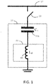
- a bus 10 is coupled to a switch 20. Coupled to the switch 20 is a capacitor 30A. Capacitor 30A is coupled in series to inductor 40 which is coupled to ground.
- the size of inductor 40 is selected such that subcircuit 50 exhibits an inductive characteristic at frequencies higher than a frequency called the detuning frequency.
- This frequency can be the fundamental or the 3rd harmonic frequencies. If the system impedance is also inductive, resonance at harmonic frequencies that are higher than the detuning frequency can be avoided.
- This scheme has been widely used for low voltage ( ⁇ 600V) or medium voltage ( ⁇ 25kV) capacitors.
- Element 60 is denoted as the detuning element and 40 is the detuning inductor.
- the inductor 40 can be sized to make the total impedance of subcircuit 50 close to zero at a harmonic frequency (e.g. 300Hz).
- This subcircuit 50 then becomes a (single-tuned) harmonic filter that can trap 300Hz harmonics (see “IEEE Guide for Application and Specification of Harmonic Filters,” in IEEE Std 1531-2003, the entirety of which is hereby incorporated by reference).
- the element that enables a capacitor to filter harmonics is called the filtering element in this document.
- the filtering element is element 60 which consists of an inductor 40.
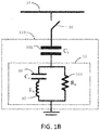
- a bus 10 is coupled to a switch 20 which leads to a capacitor 30B.
- This capacitor 30B is connected in series with a subcircuit 70.
- Within subcircuit 70 are two branches in parallel to one another -- one branch has an auxiliary capacitor 80 in series with a detuning inductor 90.
- the other branch has a damping resistor 100.
- the function of the detuning inductor 90 is similar to that of the detuning inductor 40 in Figure 1A , that is, to change the frequency response of the combined subcircuit 110.
- the damping resistor 100 further improves the resonance mitigation performance by absorbing the harmonic energy that oscillates between subcircuit 110 and the system.
- the auxiliary capacitor 80 is connected in series with the detuning inductor 90 to reduce the loss of the damping resistor 100 at the fundamental frequency.
- This configuration has been widely used to damp harmonic resonance for capacitors at high voltages (>25kV).
- Subcircuit 70 can therefore be characterized as a damping element.
- auxiliary capacitor 80, inductor 90, and resistor 100 can be sized to render the subcircuit 110 into a high-pass harmonic filter (see “IEEE Guide for Application and Specification of Harmonic Filters,” in IEEE Std 1531-2003, the entirety of which is hereby incorporated by reference).
- the topology of subcircuit 110 is commonly called a C-type filter in industry and subcircuit 70 is its filtering element in Figure 1B .
- a bus 200 is used to connect four circuit branches, each branch having a switch (210, 220, 230, 240) and a capacitor (250, 260, 270, 280).
- capacitors 250, 260, 270, 280 are switchable capacitors. These capacitors are connected to the same bus 200 by switches 210, 220, 230, 240. The capacitors are switched on or off according to the reactive power requirement of the system.
- resonance mitigation elements in the form of either a detuning element or a damping element is added to each capacitor.
- These resonance mitigation elements 290, 300, 310, 320 are each directly coupled to a capacitor.
- These resonance mitigation elements can take any number of forms. For example, these elements 290, 300, 310, 320 may take the form such as those shown as element 60 or subcircuit 70 in Figures 1A and 1B .
- elements 290, 300, 310, 320 can be sized to become filtering elements. It should be clear that if there are N switchable capacitors, N detuning, damping or filtering elements are needed. This increases the cost and space requirements for the entire apparatus.
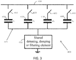
- a bus 400 couples a number of circuit branches to each other in parallel. Each branch is coupled in parallel with other branches between coupling point 400 and coupling point 405 with each branch having a switch and a capacitor in series. Thus, each one of switches 410, 420, 430, 440 is coupled in series with capacitor 450, 460, 470, 480.
- each one of switches 410, 420, 430, 440 is coupled in series with capacitor 450, 460, 470, 480.
- coupled between coupling point 405 and ground is subcircuit 490. It should be clear that while this example is coupled to ground, other embodiments of the invention may be ungrounded or may be coupled to other circuits or circuit elements.
- Circuit 403 has four switchable capacitors 450, 460, 470, 480 connected to the same bus 400. These capacitors are switched on or off (using switches 410, 420, 430, 440) according to the reactive power requirements of the system. To prevent harmonic resonance that may be caused by any one of the capacitors, a resonance mitigation element or subcircuit 490 is added and it is shared by the four capacitors 450, 460, 470, 480.
- the subcircuit 490 is designed such that it will provide adequate detuning or damping capability for all possible on/off combinations of the capacitors. Subcircuit 490 can also be designed to turn the switchable capacitors into switchable harmonic filters.
- Subcircuit 490 can take many forms and some of these will be illustrated later in this document. Compared with the existing approach in Figure 2 that requires each capacitor to be coupled to a specific resonance mitigation or harmonic filtering element 290, 300, 310, 320, the present invention reduces cost and space requirements. In one example (to be discussed below), the embodiment illustrated in Fig. 5 can reduce at least one-third of the costs and one half of the space requirements when compared to the prior art for two switchable capacitors.
- FIG 4 presents a first specific embodiment of the present invention.
- similar components as in Figure 3 are referenced with similar reference numbers.
- each one of four capacitors 450, 460, 470, 480 is coupled in series to a specific one of four switches 410, 420, 430, 440.
- the four branches (each branch having a capacitor and a switch in series) are coupled in parallel to each other between a first connection point/bus 400 and a second connection point 405.
- Subcircuit 490 is coupled between ground and the second connection point 405.
- subcircuit 490 is an inductor 500.
- the inductor 500 if designed or sized properly, can act as a detuning inductor.
- the detuning inductor 500 can cause the entire subsystem 403 to exhibit an inductive characteristic at frequencies higher than a detuning frequency for all possible on/off combinations of the capacitors. If the system impedance is also inductive, resonance at harmonic frequencies that are higher than the detuning frequency can be avoided.
- Fig. 4 may be implemented by employing the following design methods.
- Design condition 1 reactive power support
- V 0 is the system nominal voltage and ⁇ 0 is the system fundamental angular frequency.
- Design condition 2 inductive impedance condition
- the shunt-connected subsystem 403 exhibits an inductive characteristic for frequencies higher than ⁇ T for all possible on/off combinations of the capacitors.
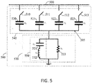
- FIG. 5 illustrated is a second specific embodiment of the present invention. Similar to the subsystem in Figure 4 , Figure 5 shows a subsystem 560 where each of four capacitors 520, 521, 522, 523 is coupled in series to a switch 510, 511, 512, 513. Each circuit branch contains a switch and a capacitor coupled in series and each circuit branch is coupled in parallel to the other circuit branches between a bus/coupling point 500 and a coupling point 505. Between the coupling point 505 and ground is a subcircuit 530. In Figure 5 , the subcircuit 530 is used as a damping element.
- the four switchable capacitors 520, 521, 522 and 523 all share the subcircuit 530, used as a damping element.
- the subcircuit 530 consists of three components split between two arms.
- the first arm 550 has a capacitor 531 coupled in series to an inductor 532 and the second arm has resistor 533.
- the arms are coupled in parallel to each other.
- the sizes of capacitor 531 and inductor 532 are selected such that arm 550 has zero reactance at the fundamental frequency. This leads to the bypass of resistor 533 and, thereby, the elimination of power loss at the fundamental frequency.
- resistor 533 damps the magnitude of the harmonic resonance for all possible on/off combinations of the capacitors.
- Fig. 5 may be implemented by employing the following design methods.
- Design condition 1 reactive power support
- V 0 is the system nominal voltage and ⁇ 0 is the system fundamental angular frequency.
- Design condition 2 fundamental frequency loss minimization
- Design condition 3 resonance-free condition
- HAR worst ( ⁇ ) is the worst-case harmonic amplification ratio at the frequency ⁇
- V post ( ⁇ ) is the harmonic voltage at the frequency ⁇ after the shunt device is connected
- V pre ( ⁇ ) is the harmonic voltage at the frequency ⁇ before the shunt device is connected.
- X z ( ⁇ ) and R z ( ⁇ ) are the reactive and real component of the harmonic impedance of the shunt device at the frequency ⁇ , respectively.
- the resonance-free condition is defined as HAR worst ( ⁇ ) less than a user selected threshold HAR limit , for frequencies higher than the tuning frequency ⁇ T , as shown in Equation (6): HAR worst ⁇ ⁇ HAR limit , for ⁇ ⁇ ⁇ T
- Cost minimization can be adopted as the fourth design condition.
- a damping element is shared among a number of capacitors coupled in parallel to each other.
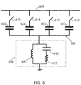
- a first coupling point 600 and a second coupling point 603 have a number of branches coupled in parallel between them. Each branch has a switch and a capacitor coupled in series. In the branches, each one of switches 610, 611, 612, 613 is coupled in series with one of the capacitors 620, 621, 622, 623. Between the second coupling point 603 and ground is a subcircuit 630.
- the shared subcircuit 630 operates as a damping element to the various capacitors coupled to the circuit.
- the subcircuit 630 has, in one embodiment, two arms in parallel with each other.
- a first arm has an inductor 631 while a second arm has a capacitor 632 and a resistor 633 coupled in series to one another.
- One variation only has the resistor in the second arm.
- the capacitor element 632 is removed and this thereby lets the impedance of capacitor 632 to be zero. Design equations for these embodiments can be established based on the principles shown in the first and second embodiments and the intended applications of the capacitors.
- FIG. 7 illustrates another embodiment of the present invention.
- each of the parallel branches between the first coupling point and the second coupling point includes an inductor in series with the capacitor and the switch.
- the first coupling point 700 and the second coupling point 703 has four branches coupled in parallel between them.
- Each branch has a switch, a capacitor, and an inductor in series.
- the switches 710, 711, 712, 713 couple or uncouple its own capacitor from the system.
- Each of the capacitors 720, 721, 722, 723 has its own series inductor 730, 731, 732, 733. All of the capacitors share a subcircuit 740 that operates as a common damping element.
- the subcircuit 740 has a topology similar to the topology of the subcircuit 630 in Figure 6 . Referring to the subcircuit 740, the configuration illustrated in Figure 7 exhibits the characteristics of a high-pass harmonic filter.
- Design equations for these embodiments can be established based on the principles shown in the first and second embodiments and the intended applications of the capacitors.
- the present invention may be used for either three-phase power systems or for single-phase power systems.
- the common application is for three-phase systems.
- the subcircuit shared by the capacitors in the circuits disclosed can be designed to perform detuning, damping, or a filtering function depending on what a user needs.
- the topologies shown in Fig. 5 and Fig. 6 can be designed to perform the function of harmonic filtering in addition to providing reactive power support.
- the embodiment illustrated in Figure 3 may have, instead of a single shared element, multiple shared elements, each of which could be switched into or out of the circuit as necessary.
- Each instance of a shared element can be coupled to connection point 405 by a switch and, as each shared element is needed, the relevant switch is closed to thereby couple that shared element into the circuit. As each shared element is not needed, the relevant switch is opened to thereby decouple that shared element from the circuit.
Landscapes
- Engineering & Computer Science (AREA)
- Power Engineering (AREA)
- Supply And Distribution Of Alternating Current (AREA)
Applications Claiming Priority (1)
| Application Number | Priority Date | Filing Date | Title |
|---|---|---|---|
| US15/663,004 US9941697B1 (en) | 2017-07-28 | 2017-07-28 | System using a subcircuit shared between capacitors for providing reactive power |
Publications (1)
| Publication Number | Publication Date |
|---|---|
| EP3435509A1 true EP3435509A1 (fr) | 2019-01-30 |
Family
ID=61526652
Family Applications (1)
| Application Number | Title | Priority Date | Filing Date |
|---|---|---|---|
| EP18159264.3A Withdrawn EP3435509A1 (fr) | 2017-07-28 | 2018-02-28 | Système utilisant un sous-circuit partagé entre des condensateurs pour fournir une puissance réactive |
Country Status (2)
| Country | Link |
|---|---|
| US (1) | US9941697B1 (fr) |
| EP (1) | EP3435509A1 (fr) |
Families Citing this family (4)
| Publication number | Priority date | Publication date | Assignee | Title |
|---|---|---|---|---|
| CN111130124B (zh) * | 2020-01-03 | 2022-03-11 | 深圳供电局有限公司 | 晶闸管投切电容器电路支路及其控制方法和制作方法 |
| CN112217212B (zh) * | 2020-10-21 | 2022-03-08 | 国网青海省电力公司电力科学研究院 | 一种用于抑制非特征谐波谐振的方法 |
| CN113193559B (zh) * | 2021-04-28 | 2022-04-12 | 通号(长沙)轨道交通控制技术有限公司 | 一种用于牵引供电系统的c型滤波器 |
| CN113691191B (zh) * | 2021-08-26 | 2023-05-30 | 中铁第四勘察设计院集团有限公司 | 一种降低长定子同步直线电机定子供电电压的装置及方法 |
Citations (14)
| Publication number | Priority date | Publication date | Assignee | Title |
|---|---|---|---|---|
| US3038134A (en) | 1958-01-18 | 1962-06-05 | Asea Ab | Means for reducing the harmonic currents in a static converter plant |
| US3535542A (en) | 1969-02-20 | 1970-10-20 | Hydro Quebec | Interconnected harmonic filters for electric power lines |
| US3555291A (en) | 1968-05-16 | 1971-01-12 | Gen Electric | Power system filter |
| US3881137A (en) | 1973-01-17 | 1975-04-29 | Ass Elect Ind | Frequency selective damping circuits |
| US3955134A (en) * | 1973-10-09 | 1976-05-04 | Woodford Dennis A | Reactance controller |
| US4406991A (en) | 1982-02-04 | 1983-09-27 | Westinghouse Electric Corp. | High power resonance filters |
| US4622474A (en) | 1983-10-25 | 1986-11-11 | Bbc Brown, Boveri & Company, Limited | Alternating-current filter circuit arrangement |
| US4864484A (en) | 1987-12-04 | 1989-09-05 | Siemens Aktiengesellschaft | High-pass element of a filter assembly for a line connected with static converters |
| US4939486A (en) | 1988-01-04 | 1990-07-03 | Asea Brown Boveri Ab | Filter equipment for power lines |
| US5565713A (en) | 1993-11-19 | 1996-10-15 | Asea Brown Boveri Ab | High-voltage filter |
| US5668418A (en) | 1994-10-25 | 1997-09-16 | Asea Brown Boveri Ab | Three-phase filter equipment including standby filter branch for switchably replacing a removed filter branch for a particular phase |
| US5805032A (en) | 1995-12-22 | 1998-09-08 | Asea Brown Boveri Ag | Electrical filter for attenuating oscillations in AC mains |
| CN104917193B (zh) * | 2015-06-25 | 2017-02-22 | 西安交通大学 | 一种具有谐振抑制功能的混合动态无功补偿装置及方法 |
| EP3133709A1 (fr) * | 2015-08-19 | 2017-02-22 | LSIS Co., Ltd. | Appareil compensateur var statique et son procédé de fonctionnement |
-
2017
- 2017-07-28 US US15/663,004 patent/US9941697B1/en active Active
-
2018
- 2018-02-28 EP EP18159264.3A patent/EP3435509A1/fr not_active Withdrawn
Patent Citations (14)
| Publication number | Priority date | Publication date | Assignee | Title |
|---|---|---|---|---|
| US3038134A (en) | 1958-01-18 | 1962-06-05 | Asea Ab | Means for reducing the harmonic currents in a static converter plant |
| US3555291A (en) | 1968-05-16 | 1971-01-12 | Gen Electric | Power system filter |
| US3535542A (en) | 1969-02-20 | 1970-10-20 | Hydro Quebec | Interconnected harmonic filters for electric power lines |
| US3881137A (en) | 1973-01-17 | 1975-04-29 | Ass Elect Ind | Frequency selective damping circuits |
| US3955134A (en) * | 1973-10-09 | 1976-05-04 | Woodford Dennis A | Reactance controller |
| US4406991A (en) | 1982-02-04 | 1983-09-27 | Westinghouse Electric Corp. | High power resonance filters |
| US4622474A (en) | 1983-10-25 | 1986-11-11 | Bbc Brown, Boveri & Company, Limited | Alternating-current filter circuit arrangement |
| US4864484A (en) | 1987-12-04 | 1989-09-05 | Siemens Aktiengesellschaft | High-pass element of a filter assembly for a line connected with static converters |
| US4939486A (en) | 1988-01-04 | 1990-07-03 | Asea Brown Boveri Ab | Filter equipment for power lines |
| US5565713A (en) | 1993-11-19 | 1996-10-15 | Asea Brown Boveri Ab | High-voltage filter |
| US5668418A (en) | 1994-10-25 | 1997-09-16 | Asea Brown Boveri Ab | Three-phase filter equipment including standby filter branch for switchably replacing a removed filter branch for a particular phase |
| US5805032A (en) | 1995-12-22 | 1998-09-08 | Asea Brown Boveri Ag | Electrical filter for attenuating oscillations in AC mains |
| CN104917193B (zh) * | 2015-06-25 | 2017-02-22 | 西安交通大学 | 一种具有谐振抑制功能的混合动态无功补偿装置及方法 |
| EP3133709A1 (fr) * | 2015-08-19 | 2017-02-22 | LSIS Co., Ltd. | Appareil compensateur var statique et son procédé de fonctionnement |
Non-Patent Citations (6)
| Title |
|---|
| CAMPOS R C ET AL: "Mechanically Switched Capacitor with Damping Network (MSCDN) - Engineering aspects of application, design and protection", TRANSMISSION AND DISTRIBUTION CONFERENCE AND EXPOSITION: LATIN AMERICA (T&D-LA), 2010 IEEE/PES, IEEE, 8 November 2010 (2010-11-08), pages 316 - 322, XP031863413, ISBN: 978-1-4577-0488-8, DOI: 10.1109/TDC-LA.2010.5762900 * |
| KAI ZHANG ET AL: "Research on hybrid dynamic capacitor - A novel approach to VAR compensation and resonance suppression", 2015 9TH INTERNATIONAL CONFERENCE ON POWER ELECTRONICS AND ECCE ASIA (ICPE-ECCE ASIA), KOREAN INSTITUTE OF POWER ELECTRONICS, 1 June 2015 (2015-06-01), pages 2863 - 2868, XP033184569, DOI: 10.1109/ICPE.2015.7168180 * |
| SABOT A ET AL: "A unique multipurpose damping circuit for shunt capacitor bank switching", IEEE TRANSACTIONS ON POWER DELIVERY, IEEE SERVICE CENTER, NEW YORK, NY, US, vol. 8, no. 3, 1 July 1993 (1993-07-01), pages 1173 - 1183, XP011352497, ISSN: 0885-8977, DOI: 10.1109/61.252642 * |
| W. XU ET AL.: "Resonance-Free Shunt Capacitors - Configurations, Design Methods and Comparative Analysis", IEEE TRANSACTIONS ON POWER DELIVERY, vol. 31, no. 5, October 2016 (2016-10-01), pages 2287 - 2295, XP011623683, DOI: doi:10.1109/TPWRD.2015.2507440 |
| WANG YANG ET AL: "A Shared Resonance Damping Scheme for Multiple Switchable Capacitors", IEEE TRANSACTIONS ON POWER DELIVERY, IEEE SERVICE CENTER, NEW YORK, NY, US, vol. 33, no. 4, 1 August 2018 (2018-08-01), pages 1973 - 1980, XP011683187, ISSN: 0885-8977, [retrieved on 20180509], DOI: 10.1109/TPWRD.2017.2764746 * |
| XU WILSUN ET AL: "Resonance-Free Shunt Capacitors-Configurations, Design Methods and Comparative Analysis", IEEE TRANSACTIONS ON POWER DELIVERY, IEEE SERVICE CENTER, NEW YORK, NY, US, vol. 31, no. 5, 1 October 2016 (2016-10-01), pages 2287 - 2295, XP011623683, ISSN: 0885-8977, [retrieved on 20160921], DOI: 10.1109/TPWRD.2015.2507440 * |
Also Published As
| Publication number | Publication date |
|---|---|
| US9941697B1 (en) | 2018-04-10 |
Similar Documents
| Publication | Publication Date | Title |
|---|---|---|
| EP3435509A1 (fr) | Système utilisant un sous-circuit partagé entre des condensateurs pour fournir une puissance réactive | |
| US5323304A (en) | A.C. storage module for reducing harmonic distortion in an A.C. waveform | |
| US20210391746A1 (en) | Method and device for determining parameter of passive impedance adapter applicable to vsc-hvdc | |
| CN101517854B (zh) | 电压源换流器站 | |
| CN105470963A (zh) | 一种有源电力滤波器及其控制方法 | |
| JPH01206841A (ja) | 高域通過フイルタ | |
| CN203645329U (zh) | 一种改进型lcl滤波器及逆变系统 | |
| US4760356A (en) | Power line filter | |
| CN116114156A (zh) | 具有共模滤波器的变流器 | |
| CN210839320U (zh) | 一种lclc型无源阻尼电路、单相及三相并网逆变系统 | |
| DE102010009265A1 (de) | Wechselrichter | |
| Adejumobi et al. | Harmonics mitigation on industrial loads using series and parallel resonant filters | |
| Sanjay et al. | Power quality improvement for non linear load applications using passive filters | |
| CN223391098U (zh) | 一种防雷电路及功率变换器 | |
| CN107800151B (zh) | 一种带虚拟无源滤波器的孤岛微网逆变器控制方法 | |
| Buyuk et al. | Performance evaluation of LLCL filter for active power filter | |
| JPH044814B2 (fr) | ||
| CN102222910A (zh) | 滤波系统 | |
| CN208433915U (zh) | 一种高压变频电源 | |
| CN210075073U (zh) | 一种不产生大启动电流的直流电源滤波器 | |
| Dovgun et al. | Passive filtering systems for multipulse rectifiers | |
| Mtakati et al. | Design and comparison of four branch passive harmonic filters in three phase four Wire systems | |
| Rahmani et al. | A new three phase hybrid passive filter to dampen resonances and compensate harmonics and reactive power for any type of load under distorted source conditions | |
| Upanya et al. | Harmonic Mitigation Using Active and Passive Filters | |
| Adesina et al. | Harmonic Mitigation on a 33kV Distribution Line using Passive Filters |
Legal Events
| Date | Code | Title | Description |
|---|---|---|---|
| PUAI | Public reference made under article 153(3) epc to a published international application that has entered the european phase |
Free format text: ORIGINAL CODE: 0009012 |
|
| STAA | Information on the status of an ep patent application or granted ep patent |
Free format text: STATUS: THE APPLICATION HAS BEEN PUBLISHED |
|
| AK | Designated contracting states |
Kind code of ref document: A1 Designated state(s): AL AT BE BG CH CY CZ DE DK EE ES FI FR GB GR HR HU IE IS IT LI LT LU LV MC MK MT NL NO PL PT RO RS SE SI SK SM TR |
|
| AX | Request for extension of the european patent |
Extension state: BA ME |
|
| STAA | Information on the status of an ep patent application or granted ep patent |
Free format text: STATUS: THE APPLICATION IS DEEMED TO BE WITHDRAWN |
|
| 18D | Application deemed to be withdrawn |
Effective date: 20190731 |