EP3435558B1 - Drahtloskommunikationsnetzwerk, sendeempfängerknoten und verfahren - Google Patents
Drahtloskommunikationsnetzwerk, sendeempfängerknoten und verfahren Download PDFInfo
- Publication number
- EP3435558B1 EP3435558B1 EP17182765.2A EP17182765A EP3435558B1 EP 3435558 B1 EP3435558 B1 EP 3435558B1 EP 17182765 A EP17182765 A EP 17182765A EP 3435558 B1 EP3435558 B1 EP 3435558B1
- Authority
- EP
- European Patent Office
- Prior art keywords
- receiver
- nodes
- topology
- transceiver
- data
- Prior art date
- Legal status (The legal status is an assumption and is not a legal conclusion. Google has not performed a legal analysis and makes no representation as to the accuracy of the status listed.)
- Active
Links
Images


Classifications
-
- H—ELECTRICITY
- H04—ELECTRIC COMMUNICATION TECHNIQUE
- H04B—TRANSMISSION
- H04B10/00—Transmission systems employing electromagnetic waves other than radio-waves, e.g. infrared, visible or ultraviolet light, or employing corpuscular radiation, e.g. quantum communication
- H04B10/11—Arrangements specific to free-space transmission, i.e. transmission through air or vacuum
- H04B10/112—Line-of-sight transmission over an extended range
- H04B10/1123—Bidirectional transmission
-
- H—ELECTRICITY
- H04—ELECTRIC COMMUNICATION TECHNIQUE
- H04B—TRANSMISSION
- H04B10/00—Transmission systems employing electromagnetic waves other than radio-waves, e.g. infrared, visible or ultraviolet light, or employing corpuscular radiation, e.g. quantum communication
- H04B10/11—Arrangements specific to free-space transmission, i.e. transmission through air or vacuum
- H04B10/112—Line-of-sight transmission over an extended range
- H04B10/1129—Arrangements for outdoor wireless networking of information
-
- H—ELECTRICITY
- H04—ELECTRIC COMMUNICATION TECHNIQUE
- H04B—TRANSMISSION
- H04B10/00—Transmission systems employing electromagnetic waves other than radio-waves, e.g. infrared, visible or ultraviolet light, or employing corpuscular radiation, e.g. quantum communication
- H04B10/11—Arrangements specific to free-space transmission, i.e. transmission through air or vacuum
- H04B10/114—Indoor or close-range type systems
- H04B10/1143—Bidirectional transmission
Definitions
- the invention relates to a local communications network, a transceiver node for use in a local communications network, and a method for use in a local communications network having at least two transceiver nodes and a topology planning algorithm.
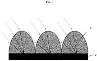
- Light field cameras organize light received onto their sensor array as a 4D field of position and light direction. This is performed, for example, by locating a microlens above a patch of the pixel array. The microlens focuses light from a small range of directions onto a position under the microlens, i.e. at a certain position light incidence angle is converted into a local position array.
- Fig. 1 shows an example of how the specific angles map to different pixel positions within the subarrays.
- An image forming lens 1 focuses a standard camera image onto this array 2.
- Light is focused onto the array in a normal camera fashion.
- Information from the camera can be organized into different types of images, for example an image representing a single direction, or a single focal plane, by selecting the data from different positions within the subarrays.
- data from across the whole array can be integrated to produce, for example the summed light from a specific direction.
- EP 1 545 027 A1 relates to a method of establishing a communication connection between a versatile first object, as well as a communication system for carrying out this method.
- the communication system comprising a laser communication unit comprising a laser transmission unit for emitting a laser beam containing encoded information and a laser receiving unit for receiving such a laser beam.
- WO 2014/053175 A1 relates to an optical validating path in an optical layer of a communications network, for client traffic having an associated service level, involves setting an optical quality margin according to the service level associated with that client traffic.
- WO 2012/167135 A1 relates to systems and methods for enabling nodes of a free-space optical communication system to maintain pointing alignment of their transmitted optical beams.
- US 2016/086994 A1 relates to techniques for fabricating an image sensor chip having a curved surface including placing a bending substrate on a first surface of an imaging sensor chip.
- a transceiver If a transceiver is off to the side of a sensor and cannot be imaged, then the sensor will have to be moved (have its viewing angle changed) to bring that transceiver into view.
- the relationship between light angle and absolute angle of the light incident on the sensor can be altered by changing the direction of the camera (naturally). However, this causes an equal change across all the light direction fields and the total angle of view of the sensor remains the same. But if the shape of the light field array surface is changed, then the angle to position function for different parts of the array will change differently.
- a local communications network comprises at least two transceiver nodes and a topology planning algorithm.
- Each transceiver node comprises an optical emitter, a reconfigurable optical receiver, a receiver configurer, an estimator algorithm, and a receiver reconfiguration procedure.
- the topology planning algorithm is configured to run on one or more transceiver nodes, to take a set of Data Quality Estimations from all transceiver nodes, choose an optimal network topology which maximizes overall network data rates, and output the result as a Current Network Topology, which is transmitted to all local nodes.
- the optical emitter may be configured to direct a light beam modulated by output data at the other transceiver nodes.
- the optical receiver may comprise a light field camera configured to integrate light collected from each different emitter and to demodulate it to produce input data, a plurality of direction actuators configured to move the camera in pitch and yaw, and a plurality of warping actuators configured to warp the sensor surface of the light field camera between different shapes.
- the receiver configurer may be configured to take a defined receiver configuration and to set the values of the direction actuators and warping actuators to those required in that configuration.
- the estimator algorithm may be configured to determine the anticipated signal quality of links to other nodes at different settings of its confirmation parameters, based on its knowledge of the data rates to those nodes experienced in the past and on known geometric effects of the changes in configuration and which is further configured to generate and to communicate to all the other nodes a data quality estimation describing this.
- the receiver reconfiguration procedure may be configured to take the Current Network Topology, to choose the receiver configuration that maximizes data rates for links within the topology whilst ignoring links not in the topology, and to send this receiver configuration to the receiver configurer.
- a transceiver node for use in a local communications network, wherein the receiver node comprises an optical emitter, a reconfigurable optical receiver, a receiver configurer, an estimator algorithm, and a receiver reconfiguration procedure.
- the optical receiver comprises a light field camera configured to integrate light collected from each different emitter and to demodulate it to produce input data, a plurality of direction actuators configured to move the camera in pitch and yaw, and a plurality of warping actuators configured to warp the sensor surface of the light field camera between different shapes.
- the receiver configurer may be configured to take a defined receiver configuration and to set the values of the direction actuators and warping actuators to those required in that configuration.
- the receiver reconfiguration procedure may be configured to take a Current Network Topology, to choose the receiver configuration that maximizes data rates for links within the topology whilst ignoring links not in the topology, and to send this receiver configuration to the receiver configurer.
- a method for a local communications network having at least two transceiver nodes and a topology planning algorithm, wherein each transceiver node comprises an optical emitter, a reconfigurable optical receiver, a receiver configurer, an estimator algorithm, a receiver reconfiguration procedure
- said method comprising the steps of: a) each transceiver node executing its estimator algorithm and generating a signal quality estimation, which is communicated to other transceiver nodes, b) the topology planning algorithm executing on the network using all the local data quality estimations and generating a current network topology and communicating the generated current network topology to all nodes, c) each node executing the receiver reconfiguration procedure and the receivers are configured using the receiver configuration for the current network topology, and repeating steps a) to c), if while exchanging data the data quality between any nodes degrades sufficiently or a specific time interval is reached.
- the issues being solved by this invention include: a network of local transceivers needs to organize itself to maintain the best communications possible, given that communication between certain transceivers may be obscured by objects between them, or two transceivers may be on the same line of sight from another transceiver, or haze and mist might degrade a communication link; and light field cameras can improve the ability to differentiate multiple observer emitters in the field of view, but sometimes a greater field of view or better angular rather than spatial resolution may improve this still further, in certain circumstances. Therefore, there are benefits to light field cameras with the ability to modify their imaging configuration when detecting signals from optical emitters.
- Light field cameras detect light and are able to determine the position of the objects in the field of view (x, y) and the direction of light incident on the sensor at that position ( ⁇ , ⁇ ). They are only able to receive data from emitters in their field of view and the ability to separate different transceivers may not be possible even with their improved ability to generate images at e.g. different focal depths.
- the data from a light field camera can be reorganized, e.g. by integrating different data from the 4D array, to integrate information at different focal depths, light directions or positions.
- the light field camera can be moved laterally or vertically, using a suitable actuator, to change the field of view of that camera.
- the shape of the imaging surface in a light field camera can also be altered so that the relationship between light direction and position on the light direction subarray varies across the camera, e.g. by warping, using an actuator, the imaging surface from flat to, for example, cylindrical or hemispherical. These changes can improve the ability to increase the field of view or to separate different transceivers according to their position and the angle of light from them, e.g. to separate their distance away.
- Local transceiver networks can reconfigure themselves if required, for example to maximize data transmission rates, by routing information to that node through one or more other nodes. Given that changes to the arrangement of receivers, e.g. their orientation, may result in improvements to one link but degradation of another link, different choices of the network topology and therefore receiver configuration of each node (seeking to maximize the quality of the data link between those connections in the topology but ignoring those connections not in the topology) may result in significantly different overall network data rates.
- the optimal choice of overall network topology can be determined if the quality of the set of inter-node links for all the local transceivers given their different receiver configurations is known.
- a receiver Given a specific network topology, a receiver can configure itself to maximize the quality of the links active in that topology whilst ignoring the links absent in the topology. Therefore, a process can be performed which continuously reconfigures the network and the receiver configurations of each node in order to maximize data transmission rates. According to the present invention, this process can be summarized as follows: a) first each transceiver estimates the communication data quality to the other local transceivers for different light field warping configurations of its receiver; b) secondly these estimates are communicated to the rest of local transceivers; c) thirdly based on the estimates from all the local transceivers a network topology is chosen which maximizes data transmission rates (e.g.
- each transceiver optimizes its light field warping receiver configuration to maximize the quality of all the links within that topology whilst ignoring the links not in the topology.
- Light field cameras with flexible light sensor arrays can be reconfigured by changing their direction and shape to improve reception or separation with other emitters in specific directions and distances, though there will be a tradeoff in terms of possibly worsening reception for other emitters.
- Networks can continually maintain optimal data rates taking advantage of the properties of the advanced optical receivers and their ability to optimize themselves for certain connections.
- FIG. 2 shows an exemplary flexible light field camera for optical receivers 30.
- the shape of the array is configured to best integrate information from one or more observed transceivers by warping the array 20 from flat to a hemispherical or a cylindrical surface.
- the light fields at the center of the array do not change, but those at the edge are altered to view light 10 more to the side of the array and less towards the center of the array.
- the mapping between light direction 10 and subarray 30 position becomes different at different positions on the whole array 20.
- a transceiver off to one side can be brought into view, whilst maintaining viewing of the transceivers already being monitored, albeit with less information integration between array elements and, therefore, decreased signal to noise.
- the method is for a local communications network having at least two transceiver nodes, wherein each transceiver node comprises an optical emitter, a reconfigurable optical receiver, a receiver configurer, an estimator algorithm, a receiver reconfiguration procedure, and a topology planning algorithm.
- each transceiver node comprises an optical emitter, a reconfigurable optical receiver, a receiver configurer, an estimator algorithm, a receiver reconfiguration procedure, and a topology planning algorithm.
- each transceiver node executes its estimator algorithm (S1) and generates a signal quality estimation, which is then communicated to the other transceiver nodes (S2).
- the topology planning algorithm is executed on the network using all the local data quality estimations (S3).
- S3 local data quality estimations
- S4 all nodes
- each node executes the receiver reconfiguration procedure using the current network topology (S5). Then, the receivers are configured using the receiver configuration for the current network topology (S6).
- the nodes continue to exchange data (S7), e.g. collect data quality, direction, distance etc. for each link, update data for estimator algorithm. If, at any moment, data quality between any of the nodes is degraded sufficiently (S8), then the process, steps S1 to S6, is repeated or if a specific time interval is reached, the process is also repeated.
Landscapes
- Engineering & Computer Science (AREA)
- Physics & Mathematics (AREA)
- Electromagnetism (AREA)
- Computer Networks & Wireless Communication (AREA)
- Signal Processing (AREA)
- Computing Systems (AREA)
- Optical Communication System (AREA)
Claims (7)
- Lokales Kommunikationsnetzwerk, das aufweist:mindestens zwei Sendeempfängerknoten, wobei jeder Sendeempfängerknoten einen optischen Sender, einen rekonfigurierbaren optischen Empfänger und einen Empfängerkonfigurator aufweist, wobei jeder Sendeempfängerknoten konfiguriert ist, einen Schätzalgorithmus auszuführen und eine Empfänger-Rekonfigurationsprozedur unter Verwendung einer gegenwärtigen Netzwerktopologie auszuführen; undeinen Topologie-Planungsalgorithmus, der konfiguriert ist, auf einem oder mehreren Sendeempfängerknoten ausgeführt zu werden, um einen Satz von Datenqualitätsschätzungen von allen Sendeempfängerknoten vorzunehmen, eine optimale Netzwerktopologie auszuwählen, die die Gesamtnetzwerkdatenraten maximiert, und das Ergebnis als gegenwärtige Netzwerktopologie auszugeben, die an alle lokalen Knoten übertragen wird.
- Lokales Kommunikationsnetzwerk nach Anspruch 1, wobei der optische Sender konfiguriert ist, einen mit Ausgangsdaten modulierten Lichtstrahl auf die anderen Sendeempfängerknoten zu richten.
- Lokales Kommunikationsnetzwerk nach Anspruch 1 oder 2, wobei der optische Empfänger aufweist:eine Lichtfeldkamera, die konfiguriert ist, von jedem anderen Sender gesammeltes Licht zu integrieren und es zu demodulieren, um Eingabedaten zu erzeugen,mehrere Richtungsstellelemente, die konfiguriert sind, die Kamera in Nick- und Gierrichtung zu bewegen, und mehrere Wölbungsstellelemente, die konfiguriert sind, die Sensorfläche der Lichtfeldkamera zwischen unterschiedlichen Formen zu wölben.
- Lokales Kommunikationsnetzwerk nach einem der Ansprüche 1 bis 3, wobei der Empfängerkonfigurator konfiguriert ist, eine definierte Empfängerkonfiguration anzunehmen und die Werte der Richtungsstellelemente und Wölbungsstellelemente auf die in dieser Konfiguration erforderlichen einzustellen.
- Lokales Kommunikationsnetzwerk nach einem der Ansprüche 1 bis 4, wobei der Schätzalgorithmus konfiguriert ist, die voraussichtliche Signalqualität von Verbindungen zu anderen Knoten bei unterschiedlichen Einstellungen seiner Bestätigungsparameter beruhend auf seiner Kenntnis der Datenraten zu diesen Knoten, die in der Vergangenheit wahrgenommen wurden, und auf bekannten geometrischen Auswirkungen von Konfigurationsänderungen zu bestimmen, und der ferner konfiguriert ist, eine Datenqualitätsschätzung, die dies beschreibt, zu erzeugen und an alle anderen Knoten zu übertragen.
- Lokales Kommunikationsnetzwerk nach einem der Ansprüche 1 bis 5, wobei die Empfänger-Rekonfigurationsprozedur konfiguriert ist, die gegenwärtige Netzwerktopologie zu übernehmen, die Empfängerkonfiguration auszuwählen, die die Datenraten für Verbindungen innerhalb der Topologie maximiert, während Verbindungen ignoriert werden, die sich nicht in der Topologie befinden, und diese Empfängerkonfiguration an den Empfängerkonfigurator zu senden.
- Verfahren für ein lokales Kommunikationsnetzwerk mit mindestens zwei Sendeempfängerknoten, wobei jeder Sendeempfängerknoten einen optischen Sender, einen rekonfigurierbaren optischen Empfänger, einen Empfängerkonfigurator, einen Schätzalgorithmus, eine Empfänger-Rekonfigurationsprozedur und einen Topologie-Planungsalgorithmus aufweist, wobei das Verfahren die Schritte aufweist:a) Ausführen durch jeden Sendeempfängerknoten seines Schätzalgorithmus (S1) und Erzeugen einer Signalqualitätsschätzung, die an andere Sendeempfängerknoten (S2) übertragen wird,b) Ausführen des Topologie-Planungsalgorithmus auf dem Netzwerk unter Verwendung aller lokalen Datenqualitätsschätzungen (S3) und Erzeugen einer gegenwärtigen Netzwerktopologie und Übertragen der erzeugten gegenwärtigen Netzwerktopologie an alle Knoten (S4),c) Ausführen durch jeden Knoten der Empfänger-Rekonfigurationsprozedur unter Verwendung der gegenwärtigen Netzwerktopologie (S5) und Konfigurieren der Empfänger unter Verwendung der Empfängerkonfiguration für die gegenwärtige Netzwerktopologie (S6), undWiederholen der Schritte a) bis c), wenn sich beim Datenaustausch die Datenqualität zwischen irgendwelchen Knoten ausreichend verschlechtert oder ein bestimmtes Zeitintervall erreicht wird.
Priority Applications (1)
| Application Number | Priority Date | Filing Date | Title |
|---|---|---|---|
| EP17182765.2A EP3435558B1 (de) | 2017-07-24 | 2017-07-24 | Drahtloskommunikationsnetzwerk, sendeempfängerknoten und verfahren |
Applications Claiming Priority (1)
| Application Number | Priority Date | Filing Date | Title |
|---|---|---|---|
| EP17182765.2A EP3435558B1 (de) | 2017-07-24 | 2017-07-24 | Drahtloskommunikationsnetzwerk, sendeempfängerknoten und verfahren |
Publications (2)
| Publication Number | Publication Date |
|---|---|
| EP3435558A1 EP3435558A1 (de) | 2019-01-30 |
| EP3435558B1 true EP3435558B1 (de) | 2021-02-17 |
Family
ID=59631547
Family Applications (1)
| Application Number | Title | Priority Date | Filing Date |
|---|---|---|---|
| EP17182765.2A Active EP3435558B1 (de) | 2017-07-24 | 2017-07-24 | Drahtloskommunikationsnetzwerk, sendeempfängerknoten und verfahren |
Country Status (1)
| Country | Link |
|---|---|
| EP (1) | EP3435558B1 (de) |
Family Cites Families (6)
| Publication number | Priority date | Publication date | Assignee | Title |
|---|---|---|---|---|
| EP1545027A1 (de) * | 2003-12-18 | 2005-06-22 | Alcatel | Robotkommunikationsystem |
| WO2012167135A1 (en) * | 2011-06-03 | 2012-12-06 | Skyfiber, Inc | Active tracking for free-space optical communication systems |
| JP6137520B2 (ja) * | 2012-09-03 | 2017-05-31 | 学校法人 工学院大学 | 空間光伝送システム |
| EP2904723A1 (de) * | 2012-10-03 | 2015-08-12 | Telefonaktiebolaget L M Ericsson (Publ) | Verfahren zur lichtwegvalidierung |
| JP6221449B2 (ja) * | 2013-07-18 | 2017-11-01 | 富士通株式会社 | ネットワーク設計装置、ネットワーク設計方法、及びネットワーク設計プログラム |
| US10373995B2 (en) * | 2014-09-19 | 2019-08-06 | Microsoft Technology Licensing, Llc | Image sensor bending using tension |
-
2017
- 2017-07-24 EP EP17182765.2A patent/EP3435558B1/de active Active
Non-Patent Citations (1)
| Title |
|---|
| None * |
Also Published As
| Publication number | Publication date |
|---|---|
| EP3435558A1 (de) | 2019-01-30 |
Similar Documents
| Publication | Publication Date | Title |
|---|---|---|
| JP6959316B2 (ja) | 高速自由空間光通信 | |
| FR2960365B1 (fr) | Appareil de communication radio, systeme de reseau radio, et procede de construction de liaison de donnees utilise pour ceux-ci | |
| JP2020014227A (ja) | 発散ビーム通信システム | |
| US20190089460A1 (en) | Co-prime optical transceiver array | |
| US20220373688A1 (en) | Lidar with microlens array and integrated photonic switch array | |
| KR102781524B1 (ko) | 패스트 빔 스티어링 시스템 기반 주파수 그래디언트 메타서페이스 장치 및 이에 대한 방법 | |
| KR20200122367A (ko) | 다중 채널의 확산-빔 광학 무선 통신을 위한 시스템 | |
| JP5257477B2 (ja) | 光空間通信装置およびその通信方法ならびに光空間通信システム | |
| KR20180122392A (ko) | 모듈식 무선 광학 안테나 | |
| US20220368420A1 (en) | Sloping single point optical aggregation | |
| Milner et al. | Autonomous reconfiguration and control in directional mobile ad hoc networks | |
| KR20230036114A (ko) | 유효 스캔 레인지에서 연속 빔 스캐닝에 대한 페이즈 컨트롤 장치 및 이에 대한 방법 | |
| Sung et al. | A hybrid radio-optical wireless system with efficient sub-centimeter localization for full-coverage indoor services | |
| EP3435558B1 (de) | Drahtloskommunikationsnetzwerk, sendeempfängerknoten und verfahren | |
| KR20230131840A (ko) | 다중 안테나 서버 및 단일 안테나 유저 설정 기반 연합러닝 방법 및 장치 | |
| KR20230005297A (ko) | Owc를 위한 주파수 그래디언트 메타서페이스 기반 패스트 빔 스티어링 전송 방법 및 장치 | |
| WO2022096402A1 (en) | An optical wireless communication device | |
| US6661546B1 (en) | Multi-aperture holographic optical element for illumination sensing in a free space optical communication system | |
| JP7751629B2 (ja) | アセットおよび/または位置に関連する数量を決定し、データを通信するための投影光学計測システム用の光学ユニット | |
| JP2021524189A (ja) | 電子操縦アンテナシステムのためのビームアライメントにおいての、または、そのビームアライメントに関係する改善 | |
| WO2009096405A1 (ja) | 空間光通信装置およびその方法 | |
| KR102627910B1 (ko) | 자유 공간 광 링크를 사용하여 네트워킹을 위한 신호 정보를 수신하기 위한 시스템 및 방법 | |
| CN113726431A (zh) | 一种基于摄像头辅助的无人机可见光通信装置和方法 | |
| CN111521993A (zh) | 一种无源纳米天线阵列接收器及三维成像系统 | |
| Yan et al. | An initial study of mobile ad hoc networks with free space optical capabilities |
Legal Events
| Date | Code | Title | Description |
|---|---|---|---|
| PUAI | Public reference made under article 153(3) epc to a published international application that has entered the european phase |
Free format text: ORIGINAL CODE: 0009012 |
|
| STAA | Information on the status of an ep patent application or granted ep patent |
Free format text: STATUS: REQUEST FOR EXAMINATION WAS MADE |
|
| 17P | Request for examination filed |
Effective date: 20180607 |
|
| AK | Designated contracting states |
Kind code of ref document: A1 Designated state(s): AL AT BE BG CH CY CZ DE DK EE ES FI FR GB GR HR HU IE IS IT LI LT LU LV MC MK MT NL NO PL PT RO RS SE SI SK SM TR |
|
| AX | Request for extension of the european patent |
Extension state: BA ME |
|
| GRAP | Despatch of communication of intention to grant a patent |
Free format text: ORIGINAL CODE: EPIDOSNIGR1 |
|
| STAA | Information on the status of an ep patent application or granted ep patent |
Free format text: STATUS: GRANT OF PATENT IS INTENDED |
|
| INTG | Intention to grant announced |
Effective date: 20201008 |
|
| GRAS | Grant fee paid |
Free format text: ORIGINAL CODE: EPIDOSNIGR3 |
|
| GRAA | (expected) grant |
Free format text: ORIGINAL CODE: 0009210 |
|
| STAA | Information on the status of an ep patent application or granted ep patent |
Free format text: STATUS: THE PATENT HAS BEEN GRANTED |
|
| AK | Designated contracting states |
Kind code of ref document: B1 Designated state(s): AL AT BE BG CH CY CZ DE DK EE ES FI FR GB GR HR HU IE IS IT LI LT LU LV MC MK MT NL NO PL PT RO RS SE SI SK SM TR |
|
| REG | Reference to a national code |
Ref country code: GB Ref legal event code: FG4D |
|
| RIN1 | Information on inventor provided before grant (corrected) |
Inventor name: WALKER, NICHOLAS Inventor name: BUNGE, CHRISTIAN-ALEXANDER Inventor name: NOLAN, JULIAN CHARLES |
|
| REG | Reference to a national code |
Ref country code: CH Ref legal event code: EP |
|
| REG | Reference to a national code |
Ref country code: DE Ref legal event code: R096 Ref document number: 602017032529 Country of ref document: DE |
|
| REG | Reference to a national code |
Ref country code: AT Ref legal event code: REF Ref document number: 1362868 Country of ref document: AT Kind code of ref document: T Effective date: 20210315 |
|
| REG | Reference to a national code |
Ref country code: IE Ref legal event code: FG4D |
|
| REG | Reference to a national code |
Ref country code: LT Ref legal event code: MG9D |
|
| REG | Reference to a national code |
Ref country code: NL Ref legal event code: MP Effective date: 20210217 |
|
| PG25 | Lapsed in a contracting state [announced via postgrant information from national office to epo] |
Ref country code: BG Free format text: LAPSE BECAUSE OF FAILURE TO SUBMIT A TRANSLATION OF THE DESCRIPTION OR TO PAY THE FEE WITHIN THE PRESCRIBED TIME-LIMIT Effective date: 20210517 Ref country code: LT Free format text: LAPSE BECAUSE OF FAILURE TO SUBMIT A TRANSLATION OF THE DESCRIPTION OR TO PAY THE FEE WITHIN THE PRESCRIBED TIME-LIMIT Effective date: 20210217 Ref country code: GR Free format text: LAPSE BECAUSE OF FAILURE TO SUBMIT A TRANSLATION OF THE DESCRIPTION OR TO PAY THE FEE WITHIN THE PRESCRIBED TIME-LIMIT Effective date: 20210518 Ref country code: FI Free format text: LAPSE BECAUSE OF FAILURE TO SUBMIT A TRANSLATION OF THE DESCRIPTION OR TO PAY THE FEE WITHIN THE PRESCRIBED TIME-LIMIT Effective date: 20210217 Ref country code: HR Free format text: LAPSE BECAUSE OF FAILURE TO SUBMIT A TRANSLATION OF THE DESCRIPTION OR TO PAY THE FEE WITHIN THE PRESCRIBED TIME-LIMIT Effective date: 20210217 Ref country code: NO Free format text: LAPSE BECAUSE OF FAILURE TO SUBMIT A TRANSLATION OF THE DESCRIPTION OR TO PAY THE FEE WITHIN THE PRESCRIBED TIME-LIMIT Effective date: 20210517 Ref country code: PT Free format text: LAPSE BECAUSE OF FAILURE TO SUBMIT A TRANSLATION OF THE DESCRIPTION OR TO PAY THE FEE WITHIN THE PRESCRIBED TIME-LIMIT Effective date: 20210617 |
|
| REG | Reference to a national code |
Ref country code: AT Ref legal event code: MK05 Ref document number: 1362868 Country of ref document: AT Kind code of ref document: T Effective date: 20210217 |
|
| PG25 | Lapsed in a contracting state [announced via postgrant information from national office to epo] |
Ref country code: SE Free format text: LAPSE BECAUSE OF FAILURE TO SUBMIT A TRANSLATION OF THE DESCRIPTION OR TO PAY THE FEE WITHIN THE PRESCRIBED TIME-LIMIT Effective date: 20210217 Ref country code: LV Free format text: LAPSE BECAUSE OF FAILURE TO SUBMIT A TRANSLATION OF THE DESCRIPTION OR TO PAY THE FEE WITHIN THE PRESCRIBED TIME-LIMIT Effective date: 20210217 Ref country code: RS Free format text: LAPSE BECAUSE OF FAILURE TO SUBMIT A TRANSLATION OF THE DESCRIPTION OR TO PAY THE FEE WITHIN THE PRESCRIBED TIME-LIMIT Effective date: 20210217 Ref country code: PL Free format text: LAPSE BECAUSE OF FAILURE TO SUBMIT A TRANSLATION OF THE DESCRIPTION OR TO PAY THE FEE WITHIN THE PRESCRIBED TIME-LIMIT Effective date: 20210217 Ref country code: NL Free format text: LAPSE BECAUSE OF FAILURE TO SUBMIT A TRANSLATION OF THE DESCRIPTION OR TO PAY THE FEE WITHIN THE PRESCRIBED TIME-LIMIT Effective date: 20210217 |
|
| PG25 | Lapsed in a contracting state [announced via postgrant information from national office to epo] |
Ref country code: IS Free format text: LAPSE BECAUSE OF FAILURE TO SUBMIT A TRANSLATION OF THE DESCRIPTION OR TO PAY THE FEE WITHIN THE PRESCRIBED TIME-LIMIT Effective date: 20210617 |
|
| PG25 | Lapsed in a contracting state [announced via postgrant information from national office to epo] |
Ref country code: SM Free format text: LAPSE BECAUSE OF FAILURE TO SUBMIT A TRANSLATION OF THE DESCRIPTION OR TO PAY THE FEE WITHIN THE PRESCRIBED TIME-LIMIT Effective date: 20210217 Ref country code: AT Free format text: LAPSE BECAUSE OF FAILURE TO SUBMIT A TRANSLATION OF THE DESCRIPTION OR TO PAY THE FEE WITHIN THE PRESCRIBED TIME-LIMIT Effective date: 20210217 Ref country code: EE Free format text: LAPSE BECAUSE OF FAILURE TO SUBMIT A TRANSLATION OF THE DESCRIPTION OR TO PAY THE FEE WITHIN THE PRESCRIBED TIME-LIMIT Effective date: 20210217 Ref country code: CZ Free format text: LAPSE BECAUSE OF FAILURE TO SUBMIT A TRANSLATION OF THE DESCRIPTION OR TO PAY THE FEE WITHIN THE PRESCRIBED TIME-LIMIT Effective date: 20210217 |
|
| REG | Reference to a national code |
Ref country code: DE Ref legal event code: R097 Ref document number: 602017032529 Country of ref document: DE |
|
| PG25 | Lapsed in a contracting state [announced via postgrant information from national office to epo] |
Ref country code: SK Free format text: LAPSE BECAUSE OF FAILURE TO SUBMIT A TRANSLATION OF THE DESCRIPTION OR TO PAY THE FEE WITHIN THE PRESCRIBED TIME-LIMIT Effective date: 20210217 Ref country code: RO Free format text: LAPSE BECAUSE OF FAILURE TO SUBMIT A TRANSLATION OF THE DESCRIPTION OR TO PAY THE FEE WITHIN THE PRESCRIBED TIME-LIMIT Effective date: 20210217 Ref country code: DK Free format text: LAPSE BECAUSE OF FAILURE TO SUBMIT A TRANSLATION OF THE DESCRIPTION OR TO PAY THE FEE WITHIN THE PRESCRIBED TIME-LIMIT Effective date: 20210217 |
|
| PLBE | No opposition filed within time limit |
Free format text: ORIGINAL CODE: 0009261 |
|
| STAA | Information on the status of an ep patent application or granted ep patent |
Free format text: STATUS: NO OPPOSITION FILED WITHIN TIME LIMIT |
|
| 26N | No opposition filed |
Effective date: 20211118 |
|
| PG25 | Lapsed in a contracting state [announced via postgrant information from national office to epo] |
Ref country code: AL Free format text: LAPSE BECAUSE OF FAILURE TO SUBMIT A TRANSLATION OF THE DESCRIPTION OR TO PAY THE FEE WITHIN THE PRESCRIBED TIME-LIMIT Effective date: 20210217 Ref country code: ES Free format text: LAPSE BECAUSE OF FAILURE TO SUBMIT A TRANSLATION OF THE DESCRIPTION OR TO PAY THE FEE WITHIN THE PRESCRIBED TIME-LIMIT Effective date: 20210217 |
|
| PG25 | Lapsed in a contracting state [announced via postgrant information from national office to epo] |
Ref country code: SI Free format text: LAPSE BECAUSE OF FAILURE TO SUBMIT A TRANSLATION OF THE DESCRIPTION OR TO PAY THE FEE WITHIN THE PRESCRIBED TIME-LIMIT Effective date: 20210217 |
|
| REG | Reference to a national code |
Ref country code: CH Ref legal event code: PL |
|
| PG25 | Lapsed in a contracting state [announced via postgrant information from national office to epo] |
Ref country code: MC Free format text: LAPSE BECAUSE OF FAILURE TO SUBMIT A TRANSLATION OF THE DESCRIPTION OR TO PAY THE FEE WITHIN THE PRESCRIBED TIME-LIMIT Effective date: 20210217 |
|
| REG | Reference to a national code |
Ref country code: BE Ref legal event code: MM Effective date: 20210731 |
|
| PG25 | Lapsed in a contracting state [announced via postgrant information from national office to epo] |
Ref country code: LI Free format text: LAPSE BECAUSE OF NON-PAYMENT OF DUE FEES Effective date: 20210731 Ref country code: IT Free format text: LAPSE BECAUSE OF FAILURE TO SUBMIT A TRANSLATION OF THE DESCRIPTION OR TO PAY THE FEE WITHIN THE PRESCRIBED TIME-LIMIT Effective date: 20210217 Ref country code: CH Free format text: LAPSE BECAUSE OF NON-PAYMENT OF DUE FEES Effective date: 20210731 |
|
| PG25 | Lapsed in a contracting state [announced via postgrant information from national office to epo] |
Ref country code: IS Free format text: LAPSE BECAUSE OF FAILURE TO SUBMIT A TRANSLATION OF THE DESCRIPTION OR TO PAY THE FEE WITHIN THE PRESCRIBED TIME-LIMIT Effective date: 20210617 Ref country code: LU Free format text: LAPSE BECAUSE OF NON-PAYMENT OF DUE FEES Effective date: 20210724 |
|
| PG25 | Lapsed in a contracting state [announced via postgrant information from national office to epo] |
Ref country code: IE Free format text: LAPSE BECAUSE OF NON-PAYMENT OF DUE FEES Effective date: 20210724 Ref country code: BE Free format text: LAPSE BECAUSE OF NON-PAYMENT OF DUE FEES Effective date: 20210731 |
|
| PG25 | Lapsed in a contracting state [announced via postgrant information from national office to epo] |
Ref country code: CY Free format text: LAPSE BECAUSE OF FAILURE TO SUBMIT A TRANSLATION OF THE DESCRIPTION OR TO PAY THE FEE WITHIN THE PRESCRIBED TIME-LIMIT Effective date: 20210217 |
|
| PG25 | Lapsed in a contracting state [announced via postgrant information from national office to epo] |
Ref country code: HU Free format text: LAPSE BECAUSE OF FAILURE TO SUBMIT A TRANSLATION OF THE DESCRIPTION OR TO PAY THE FEE WITHIN THE PRESCRIBED TIME-LIMIT; INVALID AB INITIO Effective date: 20170724 |
|
| PG25 | Lapsed in a contracting state [announced via postgrant information from national office to epo] |
Ref country code: MK Free format text: LAPSE BECAUSE OF FAILURE TO SUBMIT A TRANSLATION OF THE DESCRIPTION OR TO PAY THE FEE WITHIN THE PRESCRIBED TIME-LIMIT Effective date: 20210217 |
|
| PG25 | Lapsed in a contracting state [announced via postgrant information from national office to epo] |
Ref country code: MT Free format text: LAPSE BECAUSE OF FAILURE TO SUBMIT A TRANSLATION OF THE DESCRIPTION OR TO PAY THE FEE WITHIN THE PRESCRIBED TIME-LIMIT Effective date: 20210217 |
|
| PGFP | Annual fee paid to national office [announced via postgrant information from national office to epo] |
Ref country code: DE Payment date: 20250722 Year of fee payment: 9 |
|
| PGFP | Annual fee paid to national office [announced via postgrant information from national office to epo] |
Ref country code: GB Payment date: 20250724 Year of fee payment: 9 |
|
| PGFP | Annual fee paid to national office [announced via postgrant information from national office to epo] |
Ref country code: FR Payment date: 20250723 Year of fee payment: 9 |
|
| PG25 | Lapsed in a contracting state [announced via postgrant information from national office to epo] |
Ref country code: TR Free format text: LAPSE BECAUSE OF FAILURE TO SUBMIT A TRANSLATION OF THE DESCRIPTION OR TO PAY THE FEE WITHIN THE PRESCRIBED TIME-LIMIT Effective date: 20210217 |