EP3435566B1 - Procédé et dispositif de transmission d'un signal de découverte - Google Patents
Procédé et dispositif de transmission d'un signal de découverte Download PDFInfo
- Publication number
- EP3435566B1 EP3435566B1 EP17770633.0A EP17770633A EP3435566B1 EP 3435566 B1 EP3435566 B1 EP 3435566B1 EP 17770633 A EP17770633 A EP 17770633A EP 3435566 B1 EP3435566 B1 EP 3435566B1
- Authority
- EP
- European Patent Office
- Prior art keywords
- mode
- drs
- transmitted
- transmitting
- transmission mode
- Prior art date
- Legal status (The legal status is an assumption and is not a legal conclusion. Google has not performed a legal analysis and makes no representation as to the accuracy of the status listed.)
- Active
Links
Images




Classifications
-
- H—ELECTRICITY
- H04—ELECTRIC COMMUNICATION TECHNIQUE
- H04J—MULTIPLEX COMMUNICATION
- H04J11/00—Orthogonal multiplex systems, e.g. using WALSH codes
- H04J11/0069—Cell search, i.e. determining cell identity [cell-ID]
- H04J11/0073—Acquisition of primary synchronisation channel, e.g. detection of cell-ID within cell-ID group
-
- H—ELECTRICITY
- H04—ELECTRIC COMMUNICATION TECHNIQUE
- H04L—TRANSMISSION OF DIGITAL INFORMATION, e.g. TELEGRAPHIC COMMUNICATION
- H04L5/00—Arrangements affording multiple use of the transmission path
- H04L5/003—Arrangements for allocating sub-channels of the transmission path
- H04L5/0048—Allocation of pilot signals, i.e. of signals known to the receiver
-
- H—ELECTRICITY
- H04—ELECTRIC COMMUNICATION TECHNIQUE
- H04B—TRANSMISSION
- H04B7/00—Radio transmission systems, i.e. using radiation field
- H04B7/02—Diversity systems; Multi-antenna system, i.e. transmission or reception using multiple antennas
- H04B7/04—Diversity systems; Multi-antenna system, i.e. transmission or reception using multiple antennas using two or more spaced independent antennas
- H04B7/0408—Diversity systems; Multi-antenna system, i.e. transmission or reception using multiple antennas using two or more spaced independent antennas using two or more beams, i.e. beam diversity
-
- H—ELECTRICITY
- H04—ELECTRIC COMMUNICATION TECHNIQUE
- H04J—MULTIPLEX COMMUNICATION
- H04J11/00—Orthogonal multiplex systems, e.g. using WALSH codes
-
- H—ELECTRICITY
- H04—ELECTRIC COMMUNICATION TECHNIQUE
- H04J—MULTIPLEX COMMUNICATION
- H04J11/00—Orthogonal multiplex systems, e.g. using WALSH codes
- H04J11/0069—Cell search, i.e. determining cell identity [cell-ID]
-
- H—ELECTRICITY
- H04—ELECTRIC COMMUNICATION TECHNIQUE
- H04J—MULTIPLEX COMMUNICATION
- H04J11/00—Orthogonal multiplex systems, e.g. using WALSH codes
- H04J11/0069—Cell search, i.e. determining cell identity [cell-ID]
- H04J11/0076—Acquisition of secondary synchronisation channel, e.g. detection of cell-ID group
-
- H—ELECTRICITY
- H04—ELECTRIC COMMUNICATION TECHNIQUE
- H04L—TRANSMISSION OF DIGITAL INFORMATION, e.g. TELEGRAPHIC COMMUNICATION
- H04L1/00—Arrangements for detecting or preventing errors in the information received
- H04L1/004—Arrangements for detecting or preventing errors in the information received by using forward error control
- H04L1/0056—Systems characterized by the type of code used
- H04L1/0061—Error detection codes
-
- H—ELECTRICITY
- H04—ELECTRIC COMMUNICATION TECHNIQUE
- H04L—TRANSMISSION OF DIGITAL INFORMATION, e.g. TELEGRAPHIC COMMUNICATION
- H04L1/00—Arrangements for detecting or preventing errors in the information received
- H04L1/12—Arrangements for detecting or preventing errors in the information received by using return channel
- H04L1/16—Arrangements for detecting or preventing errors in the information received by using return channel in which the return channel carries supervisory signals, e.g. repetition request signals
- H04L1/18—Automatic repetition systems, e.g. Van Duuren systems
-
- H—ELECTRICITY
- H04—ELECTRIC COMMUNICATION TECHNIQUE
- H04W—WIRELESS COMMUNICATION NETWORKS
- H04W48/00—Access restriction; Network selection; Access point selection
- H04W48/16—Discovering, processing access restriction or access information
-
- H—ELECTRICITY
- H03—ELECTRONIC CIRCUITRY
- H03M—CODING; DECODING; CODE CONVERSION IN GENERAL
- H03M13/00—Coding, decoding or code conversion, for error detection or error correction; Coding theory basic assumptions; Coding bounds; Error probability evaluation methods; Channel models; Simulation or testing of codes
- H03M13/03—Error detection or forward error correction by redundancy in data representation, i.e. code words containing more digits than the source words
- H03M13/05—Error detection or forward error correction by redundancy in data representation, i.e. code words containing more digits than the source words using block codes, i.e. a predetermined number of check bits joined to a predetermined number of information bits
- H03M13/09—Error detection only, e.g. using cyclic redundancy check [CRC] codes or single parity bit
-
- H—ELECTRICITY
- H04—ELECTRIC COMMUNICATION TECHNIQUE
- H04J—MULTIPLEX COMMUNICATION
- H04J11/00—Orthogonal multiplex systems, e.g. using WALSH codes
- H04J11/0069—Cell search, i.e. determining cell identity [cell-ID]
- H04J11/0079—Acquisition of downlink reference signals, e.g. detection of cell-ID
-
- H—ELECTRICITY
- H04—ELECTRIC COMMUNICATION TECHNIQUE
- H04L—TRANSMISSION OF DIGITAL INFORMATION, e.g. TELEGRAPHIC COMMUNICATION
- H04L25/00—Baseband systems
- H04L25/02—Details ; arrangements for supplying electrical power along data transmission lines
- H04L25/0202—Channel estimation
- H04L25/0224—Channel estimation using sounding signals
-
- H—ELECTRICITY
- H04—ELECTRIC COMMUNICATION TECHNIQUE
- H04L—TRANSMISSION OF DIGITAL INFORMATION, e.g. TELEGRAPHIC COMMUNICATION
- H04L5/00—Arrangements affording multiple use of the transmission path
- H04L5/0001—Arrangements for dividing the transmission path
- H04L5/0003—Two-dimensional division
- H04L5/0005—Time-frequency
- H04L5/0007—Time-frequency the frequencies being orthogonal, e.g. OFDM(A) or DMT
Definitions
- a next-generation wireless communication system is required to support various user environments and greater communication capacity.
- Representative issues considered in the next-generation system include massive machine type communications (MTC) for providing various services anytime anywhere by connecting a plurality of devices, ultra-reliable and low-latency communications (URLLC) considering a service sensitive to reliability and latency, or the like.
- MTC massive machine type communications
- URLLC ultra-reliable and low-latency communications
- one very narrow beam may be transmitted at one time point. Although coverage capable of serving the wireless device increases, it may be necessary to align a beam direction to the wireless device due to an excessively narrow angle. When a wide beam is transmitted using the same transmit power, coverage to be supported may be reduced.
- the present invention provides a method for transmitting a discovery reference signal (DRS) in a wireless communication system, and a device using the method.
- DRS discovery reference signal
- a method for transmitting a discovery reference signal (DRS) in a wireless communication is provided as set forth in the appended claims.
- DRS discovery reference signal
- a device for transmitting a discovery reference signal (DRS) in a wireless communication system is provided as set forth in the appended claims.
- DRS discovery reference signal
- a service can be adaptively provided in various environments by changing cell coverage.
- a wireless device may be fixed or mobile, and may be referred to as another terminology, such as a user equipment (UE), a mobile station (MS), a mobile terminal (MT), a user terminal (UT), a subscriber station (SS), a personal digital assistant (PDA), a wireless modem, a handheld device, etc.
- the wireless device may also be a device supporting only data communication such as a machine-type communication (MTC) device.
- MTC machine-type communication
- Abase station is generally a fixed station that communicates with the wireless device, and may be referred to as another terminology, such as an evolved-NodeB (eNB), a base transceiver system (BTS), an access point, etc.
- eNB evolved-NodeB
- BTS base transceiver system
- access point etc.
- 3GPP 3rd generation partnership project
- LTE long term evolution
- TS 3rd generation partnership project
- FIG. 1 shows an example of a subframe to which the present invention is applied.
- a subframe includes a plurality of orthogonal frequency division multiplexing (OFDM) symbols, and a time of transmitting one subframe is referred to as 1 transmission time interval (TTI).
- TTI transmission time interval
- one subframe includes 14 OFDM symbols, this is for exemplary purposes only.
- a downlink (DL) control channel may be transmitted in first one or more OFDM symbols of the subframe. This is referred to as a DL control region.
- An uplink (UL) control channel may be transmitted in last one or more OFDM symbols of the subframe. This is referred to as a UL control region.
- DL scheduling, UL scheduling, or the like may be transmitted through the DL control channel.
- Hybrid automatic repeat request (HARQ) ACK/NACK, channel quality indicator (CQI), or the like may be transmitted through the UL control channel.
- HARQ hybrid automatic repeat request
- CQI channel quality indicator
- DL data or UL data may be transmitted in OFDM symbols located in a middle portion. This is referred to as a DL/UL data region. Some or all of the OFDM symbols may be set to a guard period at a time of switching from DL transmission to UL transmission.
- DL transmission and UL transmission may be sequentially performed in one subframe to decrease a time required until data is retransmitted and to minimize latency of data transmission.
- a BS may periodically transmit a discovery reference signal (DRS).
- the DRS may be used for cell discovery, downlink synchronization, downlink measurement, or the like.
- a downlink (DL) signal based on the existing 3GPP LTE may be used as the DRS.
- At least any one of a cell specific reference signal (CRS), a primary synchronization signal (PSS), a secondary synchronization signal (SSS), and a channel state information-reference signal (CSI-RS) and/or a combination thereof may be used.
- CRS cell specific reference signal
- PSS primary synchronization signal
- SSS secondary synchronization signal
- CSI-RS channel state information-reference signal
- a DRS includes a PSS, an SSS, and a PBCH.
- the PSS and SSS refer to a first synchronization signal and second synchronization signal for DL synchronization, and there is no limitation in a structure thereof.
- the PBCH refers to a channel which transfers broadcast information to be sent to devices in a cell, and there is no limitation in a structure thereof.
- the PSS, SSS, and PBCH included in the DRS are transmitted in one OFDM symbol.
- the present invention is not limited thereto, and thus the DRS may be transmitted in a subframe or specific time unit.
- coverage refers to a maximum distance in which the DRS transmitted by a BS can arrive at a wireless device with proper reception quality.
- a narrow beam refers to a beam which supports small directivity and great coverage by supporting a small angle of arrival with respect to a direction of directivity.
- a wide beam refers to a beam which supports great directivity and small coverage by supporting a great angle of arrival with respect to a direction of directivity.
- FIG. 2 shows a DRS transmission
- the narrow beam may be switched in various time units. Switching may be performed in unit of one or more OFDM symbols or one or more subframes. Hereinafter, it is assumed that the narrow beam is switched in an OFDM symbol unit. It may be assumed that a DRS is transmitted through different beams (i.e., beams transmitted with different angles) for each OFDM symbol.
- Subfigure (B) of FIG. 2 shows a repetition mode in which a wide beam having relatively great directivity is repeatedly transmitted.
- a DRS may be transmitted through each wide beam.
- the DRS may be repeatedly transmitted through the same beam (i.e., a beam transmitted with the same angle) through a plurality of OFDM symbols.
- the wireless device may attempt to detect the DRS for each OFDM symbol under the assumption that the DRS is independently transmitted in each OFDM symbol.
- the wireless device may attempt detection by combining received DRSs under the assumption that a plurality of DRSs to be received in a plurality of OFDM symbols are transmitted in the same beam.
- the attempting of the detection through the combination may mean that channel estimation can be performed under the assumption that wireless channel parameters (Doppler spread, delay spread, frequency offset, etc.) have the same or strong correlation.
- the wireless device may only be able to perform channel estimation and combination estimation under the assumption that wireless channels experienced by the received DRSs have the same or strong correlation, and it may not be necessary to know whether a corresponding DRS is transmitted through the same beam.
- a BS can select and apply one of the switching mode and the repetition mode according to an antenna configuration, a network environment, coverage to be supported, or the like.
- the BS may select one of the switching mode and the repetition mode as a DRS transmission mode, and may transmit the DRS at transmission timing determined according to the selected DRS transmission mode.
- the wireless device may attempt both DRS detection assuming the switching mode and DRS detection assuming the repetition mode at the transmission timing.
- the wireless device may know the DRS transmission mode on the basis of the DRS detected with higher reliability or higher energy.
- the wireless device may first attempt PSS/SSS detection assuming the switching mode and PSS/SSS detection assuming the repetition mode at transmitting timing.
- the wireless device may attempt PBCH detection according to the detected DRS transmission mode.
- the BS may transmit the PSS and SSS in the DRS in different OFDM symbols.
- the number of repetitions required to support the coverage may be decreased by including maximum power that can be allocated to each of the PSS and the SSS.
- the PBCH may be transmitted in different OFDM symbols.
- the wireless device may find out the DRS transmission mode by using that the PSS, the SSS, and the PBCH are transmitted in one OFDM symbol in the switching mode and the PSS, the SSS, and the PBCH are transmitted in different OFDM symbols in the repetition mode.
- a position of a frequency at which the SSS is transmitted or a sequence used for the SSS may be applied differently between the two DRS transmission modes, so that the wireless device can detect the DRS transmission mode.
- a mode in which the PSS/SSS in the DRS is repeatedly transmitted in one OFDM symbol may be referred to as a first repetition mode, and a mode in which the PSS/SSS in the DRS is transmitted in different OFDM symbols may be a referred to as a second repetition mode.
- the BS may select one of the switching mode, the first repetition mode, and the second repetition mode as the DRS transmission mode.
- FIG. 3 shows DRS transmission.
- a BS may transmit a PSS and an SSS through different transmission modes.
- the BS may transmit the PSS by applying a repetition mode, and may transmit the SSS by selecting one of the switching mode and the repetition mode. It is shown herein that the BS transmits the PSS in first three OFDM symbols by applying the repetition mode, and transmits the SSS in second three OFDM symbols by applying the switching mode.
- a PBCH may be transmitted according to a transmission mode of the PSS or a transmission mode of the SSS.
- the wireless device first attempts to detect the PSS by assuming the repetition mode.
- the wireless device may attempt both detection assuming the repetition mode and detection assuming the switching mode in order to receive the SSS.
- the PSS may include information on the transmission mode of the SSS in order to detect the SSS.
- the wireless device may detect the PSS, confirm the transmission mode of the SSS on the basis of the detected PSS, and may attempt to detect the SSS.
- the transmission mode of the SSS may be indicated by a combination of sequences used in the PSS, an order, a frequency arrangement, and a combination of them.
- the wireless device may attempt PBCH decoding by assuming the same transmission mode as in the PSS in an OFDM symbol in which the PSS is received, and may attempt PBCH decoding by assuming the same transmission mode as in the SSS in an OFDM symbol in which the SSS is received.
- Decoding may be attempted by combining PBCHs received in an OFDM symbol in which the PSS is received and PBCHs received in an OFDM symbol in which the SSS is received.
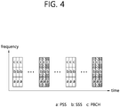
- FIG. 4 shows DRS transmission according to an embodiment of the present invention.
- a BS transmits a DRS according to a repetition mode at first timing, and transmits the DRS according to a switching mode at second timing.
- the BS transmits the DRS by selecting one of the repetition mode and the switching mode at a specific period.
- a wireless device may attempt DRS detection by assuming only one transmission mode when initial connection is achieved, and may attempt DRS detection for the two transmission modes after a connection with the BS is successful.
- the wireless device attempts only DRS detection assuming the repetition mode.
- the wireless device may acquire information on a DRS transmission structure and transmission timing, and may attempt DRS detection for the two transmission modes in a state of being connected with the BS.
- the wireless device may perform radio resource management (RRM) on the DRS transmitted in the repetition mode, and may report the measurement result to the BS.
- RRM radio resource management
- the wireless device may determine a DL synchronization level and thus may determine whether to maintain the connection to the BS or to switch the connection to a neighboring BS.
- the wireless device may report to the BS not only a measurement result for the DRS transmitted in the switching mode but also the DRS transmitted in the switching mode.
- the BS may inform mode information on the DRS transmission mode through the PBCH.
- the mode information may include at least one of information indicating the switching mode or the repetition mode, a period in which the transmission mode is changed, and the number of repetitions.
- a payload transmitted on the PBCH may include the mode information.
- the mode information may be masked to cyclic redundancy check (CRC) of the payload transmitted on the PBCH.
- CRC cyclic redundancy check
- a radio resource to which the payload transmitted on the PBCH is mapped may be placed differently according to the mode information.
- FIG. 5 shows an example of indicating mode information by using a PBCH.
- Time-frequency resource mapping of a payload of a PBCH may be differentiated according to a DRS transmission mode. For example, in a switching mode, the payload of the PBCH is encoded independently for each OFDM symbol. This means that the payload of the PBCH transmitted in each OFDM symbol has corresponding CRC. In a repetition mode, the payload of the PBCH is jointly encoded across repeated OFDM symbols. This means that the payload of the PBCH transmitted in the repeated OFDM symbols has only one CRC.
- the DRS transmission mode may be selected for each frequency band in which a network operates.
- the wireless device may assume a predetermined DRS transmission mode according to a frequency band in which the wireless device attempts to detect the DRS.
- the switching mode may be applied to a high frequency band (e.g., > 6GHz) in which a narrow beam configuration using a relatively large number of antenna ports is easy, and the repetition mode may be applied to a frequency band lower than that.
- the wireless device may attempt to detect the DRS on the basis of the plurality of DRS transmission modes.
- the DRS transmission mode which is applied by the wireless device in each frequency band may be stored in a memory.
- FIG. 6 is a block diagram showing a wireless communication system.
- a wireless device 50 includes a processor 51, a memory 52, and a transceiver 53.
- the memory 52 is coupled to the processor 51, and stores various instructions executed by the processor 51.
- the transceiver 53 is coupled to the processor 51, and transmits and/or receives a radio signal.
- the processor 51 implements the proposed functions, procedures, and/or methods. In the aforementioned embodiment, an operation of the wireless device may be implemented by the processor 51. When the aforementioned embodiment is implemented with a software instruction, the instruction may be stored in the memory 52, and may be executed by the processor 51 to perform the aforementioned operation.
- a BS 60 includes a processor 61, a memory 62, and a transceiver 63.
- the BS 60 may operate in an unlicensed band.
- the memory 62 is coupled to the processor 61, and stores various instructions executed by the processor 61.
- the transceiver 63 is coupled to the processor 61, and transmits and/or receives a radio signal.
- the processor 61 implements the proposed functions, procedures, and/or methods. In the aforementioned embodiment, an operation of the BS may be implemented by the processor 61.
- the processor may include Application-Specific Integrated Circuits (ASICs), other chipsets, logic circuits, and/or data processors.
- the memory may include Read-Only Memory (ROM), Random Access Memory (RAM), flash memory, memory cards, storage media and/or other storage devices.
- the transceiver may include a baseband circuit for processing a radio signal.
- the above-described embodiment is implemented in software, the above-described scheme may be implemented using a module (process or function) which performs the above function.
- the module may be stored in the memory and executed by the processor.
- the memory may be disposed to the processor internally or externally and connected to the processor using a variety of well-known means.
Landscapes
- Engineering & Computer Science (AREA)
- Signal Processing (AREA)
- Computer Networks & Wireless Communication (AREA)
- Databases & Information Systems (AREA)
- Computer Security & Cryptography (AREA)
- Mobile Radio Communication Systems (AREA)
Claims (4)
- Procédé d'émission d'un signal de référence de découverte, DRS, dans un système de communication sans fil, le procédé comprenant :la sélection, par une station de base (60), d'un parmi un mode de commutation et un mode de répétition comme un mode d'émission de DRS, le mode de commutation étant un mode pour émettre un faisceau étroit, le mode de répétition étant un mode pour émettre un faisceau large, dans lequel le faisceau étroit couvre une plus grande couverture de la station de base que le faisceau large ;l'émission, par la station de base (60), d'un canal de diffusion sur une pluralité de symboles de multiplexage par répartition en fréquences orthogonales, OFDM, sur la base du mode d'émission de DRS sélectionné ; etl'émission, par la station de base (60), du DRS en fonction du mode d'émission de DRS sélectionné,dans lequellorsque le mode de commutation est sélectionné comme le mode d'émission de DRS, un contrôle de redondance cyclique, CRC, du canal de diffusion est émis dans chacun de la pluralité de symboles OFDM, etlorsque le mode de répétition est sélectionné comme le mode d'émission de DRS, un unique CRC du canal de diffusion est émis sur la totalité de la pluralité de symboles OFDM.
- Procédé selon la revendication 1, dans lequel le DRS comprend un signal de synchronisation pour une synchronisation de liaison descendante.
- Dispositif (60) d'émission d'un signal de référence de découverte, DRS, dans un système de communication sans fil, le dispositif comprenant :un émetteur-récepteur (63) configuré pour émettre et recevoir un signal radio ; etun processeur (61) couplé en fonctionnement à l'émetteur-récepteur (63) et configuré pour :sélectionner un parmi un mode de commutation et un mode de répétition comme un mode d'émission de DRS, le mode de commutation étant un mode pour émettre un faisceau étroit, le mode de répétition étant un mode pour émettre un faisceau large, dans lequel le faisceau étroit couvre une plus grande couverture de la station de base que le faisceau large ;contrôler l'émetteur-récepteur (63) pour émettre un canal de diffusion sur une pluralité de symboles de multiplexage par répartition en fréquences orthogonales, OFDM, sur la base du mode d'émission de DRS sélectionné ; etcontrôler l'émetteur-récepteur (63) pour émettre le DRS en fonction du mode d'émission de DRS sélectionné,dans lequellorsque le mode de commutation est sélectionné comme le mode d'émission de DRS, un contrôle de redondance cyclique, CRC, du canal de diffusion est émis dans chacun de la pluralité de symboles OFDM, etlorsque le mode de répétition est sélectionné comme le mode d'émission de DRS, un unique CRC du canal de diffusion est émis sur la totalité de la pluralité de symboles OFDM.
- Dispositif (60) selon la revendication 3, dans lequel le DRS comprend un signal de synchronisation pour une synchronisation de liaison descendante.
Applications Claiming Priority (2)
| Application Number | Priority Date | Filing Date | Title |
|---|---|---|---|
| US201662311919P | 2016-03-23 | 2016-03-23 | |
| PCT/KR2017/003116 WO2017164663A1 (fr) | 2016-03-23 | 2017-03-23 | Procédé et dispositif de transmission d'un signal de découverte |
Publications (3)
| Publication Number | Publication Date |
|---|---|
| EP3435566A1 EP3435566A1 (fr) | 2019-01-30 |
| EP3435566A4 EP3435566A4 (fr) | 2019-08-14 |
| EP3435566B1 true EP3435566B1 (fr) | 2020-12-02 |
Family
ID=59900495
Family Applications (1)
| Application Number | Title | Priority Date | Filing Date |
|---|---|---|---|
| EP17770633.0A Active EP3435566B1 (fr) | 2016-03-23 | 2017-03-23 | Procédé et dispositif de transmission d'un signal de découverte |
Country Status (3)
| Country | Link |
|---|---|
| US (1) | US10644852B2 (fr) |
| EP (1) | EP3435566B1 (fr) |
| WO (1) | WO2017164663A1 (fr) |
Families Citing this family (8)
| Publication number | Priority date | Publication date | Assignee | Title |
|---|---|---|---|---|
| US10855407B2 (en) * | 2016-05-09 | 2020-12-01 | Apple Inc. | Extended physical broadcast channel design for 5G standalone system |
| US10673552B2 (en) * | 2017-04-14 | 2020-06-02 | Qualcomm Incorporated | Synchronization signal block designs for wireless communication |
| EP3714626B1 (fr) * | 2017-11-22 | 2021-08-11 | Telefonaktiebolaget LM Ericsson (publ) | Gestion de ressources radio dans des systèmes de communication sans fil |
| US11457472B2 (en) * | 2017-12-18 | 2022-09-27 | Samsung Electronics Co., Ltd. | Method and apparatus for initial access block on stand-alone NR unlicensed spectrum |
| CN110166393B (zh) * | 2018-02-13 | 2021-06-25 | 展讯通信(上海)有限公司 | 同步信号块的发送、接收方法及装置 |
| US10756784B2 (en) | 2018-04-03 | 2020-08-25 | Qualcomm Incorporated | Feedback of beam repetition and diversity mode |
| WO2020065894A1 (fr) * | 2018-09-27 | 2020-04-02 | 三菱電機株式会社 | Station de base, dispositif de terminal, et procédé de positionnement |
| CN112752274B (zh) * | 2019-10-29 | 2022-08-19 | 上海华为技术有限公司 | 波束切换方法以及波束切换装置 |
Family Cites Families (19)
| Publication number | Priority date | Publication date | Assignee | Title |
|---|---|---|---|---|
| US8331265B2 (en) | 2009-04-20 | 2012-12-11 | Samsung Electronics Co., Ltd. | System and method for adaptive beamforming training using fixed time window for heterogeneous antenna systems |
| KR101928434B1 (ko) | 2011-08-30 | 2018-12-13 | 삼성전자주식회사 | 전기 습윤 소자 및 그 제조 방법 |
| KR101847400B1 (ko) * | 2011-09-01 | 2018-04-10 | 삼성전자주식회사 | 무선 통신 시스템에서 최적의 빔을 선택하기 위한 장치 및 방법 |
| CN104335500B (zh) | 2012-05-25 | 2018-11-06 | 三星电子株式会社 | 在使用波束形成的移动通信系统中发送和接收参考信号的方法和装置 |
| KR102009743B1 (ko) | 2012-06-29 | 2019-10-21 | 삼성전자주식회사 | 빔포밍 기반 통신 시스템에서 신호를 전송하는 방법 및 장치 |
| US9451639B2 (en) * | 2013-07-10 | 2016-09-20 | Samsung Electronics Co., Ltd. | Method and apparatus for coverage enhancement for a random access process |
| US9775134B2 (en) * | 2013-09-20 | 2017-09-26 | Samsung Electronics Co., Ltd. | System and method for coverage enhancements of broadcast channels |
| JP6673824B2 (ja) | 2013-11-04 | 2020-04-01 | エルジー エレクトロニクス インコーポレイティド | 無線通信システムにおいて信号を送信する方法及び装置 |
| EP3675566B1 (fr) * | 2014-01-29 | 2022-07-06 | InterDigital Patent Holdings, Inc. | Procédé et appareil d'accès et d'adaptation de liaisons pour transmissions sans fil à couverture améliorée |
| JP2015164281A (ja) * | 2014-01-31 | 2015-09-10 | 株式会社Nttドコモ | ユーザ装置、基地局、及び通信方法 |
| JP6438203B2 (ja) * | 2014-03-20 | 2018-12-12 | 株式会社Nttドコモ | 基地局及びユーザ装置 |
| US11057921B2 (en) * | 2014-10-01 | 2021-07-06 | Samsung Electronics Co., Ltd. | System and method for improving spectral efficiency and coverage for user equipments |
| EP3225070A1 (fr) * | 2014-11-26 | 2017-10-04 | IDAC Holdings, Inc. | Accès initial dans des systèmes sans fil haute fréquence |
| CN114125872B (zh) * | 2015-05-14 | 2024-07-02 | 瑞典爱立信有限公司 | 用于采用波束成形的drs的测量规程 |
| TWI767306B (zh) * | 2015-11-10 | 2022-06-11 | 美商Idac控股公司 | 波束成形系統下行控制頻道設計及傳訊 |
| TWI720052B (zh) * | 2015-11-10 | 2021-03-01 | 美商Idac控股公司 | 無線傳輸/接收單元和無線通訊方法 |
| EP3384648A1 (fr) * | 2015-12-03 | 2018-10-10 | IDAC Holdings, Inc. | Queue de zéro et formes d'onde fondées sur un mot unique pour un dft-s ofdm et un ofdm |
| WO2017096131A1 (fr) * | 2015-12-03 | 2017-06-08 | Idac Holdings, Inc. | Utilisation à la fois d'un préfixe cyclique et d'une queue à zéro dans l'ofdm à étalement dft |
| KR20230128391A (ko) * | 2016-03-03 | 2023-09-04 | 인터디지탈 패튼 홀딩스, 인크 | 빔 포밍 기반의 시스템에서의 빔 제어를 위한 방법및 장치 |
-
2017
- 2017-03-23 WO PCT/KR2017/003116 patent/WO2017164663A1/fr not_active Ceased
- 2017-03-23 US US16/079,388 patent/US10644852B2/en active Active
- 2017-03-23 EP EP17770633.0A patent/EP3435566B1/fr active Active
Non-Patent Citations (1)
| Title |
|---|
| None * |
Also Published As
| Publication number | Publication date |
|---|---|
| US20190028253A1 (en) | 2019-01-24 |
| US10644852B2 (en) | 2020-05-05 |
| EP3435566A1 (fr) | 2019-01-30 |
| WO2017164663A1 (fr) | 2017-09-28 |
| EP3435566A4 (fr) | 2019-08-14 |
Similar Documents
| Publication | Publication Date | Title |
|---|---|---|
| EP3435566B1 (fr) | Procédé et dispositif de transmission d'un signal de découverte | |
| US11716663B2 (en) | Method and apparatus for user equipment (UE) monitoring behavior for beam recovery in a wireless communication system | |
| JP7404321B2 (ja) | 多アンテナmu-mimoシステムのための制御チャネル設計 | |
| EP3616330B1 (fr) | Procédé de réponse à une demande de reprise sur défaillance de faisceau | |
| EP3646483B1 (fr) | Demande de reprise après défaillance de faisceau | |
| EP2939349B1 (fr) | Procédés et appareils d'accès aléatoire dans un système de communication disposant d'un grand nombre d'antennes | |
| US10313994B2 (en) | Variable synchronization block format | |
| EP3381134B1 (fr) | Apprentissage de formation de faisceau de dispositif d'utilisateur dans des réseaux sans fil | |
| CN107211451B (zh) | 高频无线系统中的初始接入 | |
| EP3692756B1 (fr) | Positions de bloc de signal de synchronisation spécifique de faisceau et non spécifique de faisceau pour réseaux sans fil | |
| CN110999471A (zh) | 在无线通信系统中执行波束故障恢复的方法及其设备 | |
| US20180279364A1 (en) | Method and apparatus for random access in mobile communication system | |
| EP3536075A1 (fr) | Résolution de la surdité pendant une évaluation de canal libre (cca) directionnelle | |
| US11540322B2 (en) | Method for performing random access procedure between terminal and base station in wireless communication system, and device supporting same | |
| KR20190000844A (ko) | 무선 통신 시스템에서 상향링크 신호를 송수신하는 방법 및 장치 | |
| KR20150004137A (ko) | 빔포밍 시스템에서 동기 설정 및 신호 송수신 방법 및 장치 | |
| CN109478921A (zh) | 用于无线通信的方法、用户设备和基站 | |
| WO2018174766A1 (fr) | Systèmes et procédés pour commander un renvoi de harq lorsque nr et lte coexistent sur le même support | |
| US10848217B2 (en) | Network node and a wireless communication device for random access in beam-based systems | |
| KR102547003B1 (ko) | 이동 통신 시스템에서의 랜덤 액세스 방법 및 장치 | |
| CN101615940B (zh) | 用于多天线系统的天线识别方法 | |
| US10644846B2 (en) | Radio resource control | |
| EP3449677B1 (fr) | Puissance d'émission de signaux pilotes | |
| HK40011625A (en) | Method and apparatus for transmitting and receiving uplink signal in wireless communication system |
Legal Events
| Date | Code | Title | Description |
|---|---|---|---|
| STAA | Information on the status of an ep patent application or granted ep patent |
Free format text: STATUS: THE INTERNATIONAL PUBLICATION HAS BEEN MADE |
|
| PUAI | Public reference made under article 153(3) epc to a published international application that has entered the european phase |
Free format text: ORIGINAL CODE: 0009012 |
|
| STAA | Information on the status of an ep patent application or granted ep patent |
Free format text: STATUS: REQUEST FOR EXAMINATION WAS MADE |
|
| 17P | Request for examination filed |
Effective date: 20181012 |
|
| AK | Designated contracting states |
Kind code of ref document: A1 Designated state(s): AL AT BE BG CH CY CZ DE DK EE ES FI FR GB GR HR HU IE IS IT LI LT LU LV MC MK MT NL NO PL PT RO RS SE SI SK SM TR |
|
| AX | Request for extension of the european patent |
Extension state: BA ME |
|
| DAV | Request for validation of the european patent (deleted) | ||
| DAX | Request for extension of the european patent (deleted) | ||
| A4 | Supplementary search report drawn up and despatched |
Effective date: 20190716 |
|
| RIC1 | Information provided on ipc code assigned before grant |
Ipc: H04J 11/00 20060101AFI20190710BHEP Ipc: H04B 7/0408 20170101ALI20190710BHEP |
|
| GRAP | Despatch of communication of intention to grant a patent |
Free format text: ORIGINAL CODE: EPIDOSNIGR1 |
|
| STAA | Information on the status of an ep patent application or granted ep patent |
Free format text: STATUS: GRANT OF PATENT IS INTENDED |
|
| INTG | Intention to grant announced |
Effective date: 20200416 |
|
| GRAJ | Information related to disapproval of communication of intention to grant by the applicant or resumption of examination proceedings by the epo deleted |
Free format text: ORIGINAL CODE: EPIDOSDIGR1 |
|
| STAA | Information on the status of an ep patent application or granted ep patent |
Free format text: STATUS: REQUEST FOR EXAMINATION WAS MADE |
|
| GRAS | Grant fee paid |
Free format text: ORIGINAL CODE: EPIDOSNIGR3 |
|
| STAA | Information on the status of an ep patent application or granted ep patent |
Free format text: STATUS: GRANT OF PATENT IS INTENDED |
|
| GRAP | Despatch of communication of intention to grant a patent |
Free format text: ORIGINAL CODE: EPIDOSNIGR1 |
|
| INTC | Intention to grant announced (deleted) | ||
| INTG | Intention to grant announced |
Effective date: 20200917 |
|
| GRAA | (expected) grant |
Free format text: ORIGINAL CODE: 0009210 |
|
| STAA | Information on the status of an ep patent application or granted ep patent |
Free format text: STATUS: THE PATENT HAS BEEN GRANTED |
|
| AK | Designated contracting states |
Kind code of ref document: B1 Designated state(s): AL AT BE BG CH CY CZ DE DK EE ES FI FR GB GR HR HU IE IS IT LI LT LU LV MC MK MT NL NO PL PT RO RS SE SI SK SM TR |
|
| REG | Reference to a national code |
Ref country code: GB Ref legal event code: FG4D |
|
| REG | Reference to a national code |
Ref country code: AT Ref legal event code: REF Ref document number: 1342078 Country of ref document: AT Kind code of ref document: T Effective date: 20201215 Ref country code: CH Ref legal event code: EP |
|
| REG | Reference to a national code |
Ref country code: IE Ref legal event code: FG4D |
|
| REG | Reference to a national code |
Ref country code: DE Ref legal event code: R096 Ref document number: 602017028845 Country of ref document: DE |
|
| PG25 | Lapsed in a contracting state [announced via postgrant information from national office to epo] |
Ref country code: NO Free format text: LAPSE BECAUSE OF FAILURE TO SUBMIT A TRANSLATION OF THE DESCRIPTION OR TO PAY THE FEE WITHIN THE PRESCRIBED TIME-LIMIT Effective date: 20210302 Ref country code: RS Free format text: LAPSE BECAUSE OF FAILURE TO SUBMIT A TRANSLATION OF THE DESCRIPTION OR TO PAY THE FEE WITHIN THE PRESCRIBED TIME-LIMIT Effective date: 20201202 Ref country code: FI Free format text: LAPSE BECAUSE OF FAILURE TO SUBMIT A TRANSLATION OF THE DESCRIPTION OR TO PAY THE FEE WITHIN THE PRESCRIBED TIME-LIMIT Effective date: 20201202 Ref country code: GR Free format text: LAPSE BECAUSE OF FAILURE TO SUBMIT A TRANSLATION OF THE DESCRIPTION OR TO PAY THE FEE WITHIN THE PRESCRIBED TIME-LIMIT Effective date: 20210303 |
|
| REG | Reference to a national code |
Ref country code: NL Ref legal event code: MP Effective date: 20201202 |
|
| REG | Reference to a national code |
Ref country code: AT Ref legal event code: MK05 Ref document number: 1342078 Country of ref document: AT Kind code of ref document: T Effective date: 20201202 |
|
| PG25 | Lapsed in a contracting state [announced via postgrant information from national office to epo] |
Ref country code: SE Free format text: LAPSE BECAUSE OF FAILURE TO SUBMIT A TRANSLATION OF THE DESCRIPTION OR TO PAY THE FEE WITHIN THE PRESCRIBED TIME-LIMIT Effective date: 20201202 Ref country code: PL Free format text: LAPSE BECAUSE OF FAILURE TO SUBMIT A TRANSLATION OF THE DESCRIPTION OR TO PAY THE FEE WITHIN THE PRESCRIBED TIME-LIMIT Effective date: 20201202 Ref country code: LV Free format text: LAPSE BECAUSE OF FAILURE TO SUBMIT A TRANSLATION OF THE DESCRIPTION OR TO PAY THE FEE WITHIN THE PRESCRIBED TIME-LIMIT Effective date: 20201202 Ref country code: BG Free format text: LAPSE BECAUSE OF FAILURE TO SUBMIT A TRANSLATION OF THE DESCRIPTION OR TO PAY THE FEE WITHIN THE PRESCRIBED TIME-LIMIT Effective date: 20210302 |
|
| PG25 | Lapsed in a contracting state [announced via postgrant information from national office to epo] |
Ref country code: HR Free format text: LAPSE BECAUSE OF FAILURE TO SUBMIT A TRANSLATION OF THE DESCRIPTION OR TO PAY THE FEE WITHIN THE PRESCRIBED TIME-LIMIT Effective date: 20201202 Ref country code: NL Free format text: LAPSE BECAUSE OF FAILURE TO SUBMIT A TRANSLATION OF THE DESCRIPTION OR TO PAY THE FEE WITHIN THE PRESCRIBED TIME-LIMIT Effective date: 20201202 |
|
| REG | Reference to a national code |
Ref country code: LT Ref legal event code: MG9D |
|
| PG25 | Lapsed in a contracting state [announced via postgrant information from national office to epo] |
Ref country code: PT Free format text: LAPSE BECAUSE OF FAILURE TO SUBMIT A TRANSLATION OF THE DESCRIPTION OR TO PAY THE FEE WITHIN THE PRESCRIBED TIME-LIMIT Effective date: 20210405 Ref country code: SK Free format text: LAPSE BECAUSE OF FAILURE TO SUBMIT A TRANSLATION OF THE DESCRIPTION OR TO PAY THE FEE WITHIN THE PRESCRIBED TIME-LIMIT Effective date: 20201202 Ref country code: RO Free format text: LAPSE BECAUSE OF FAILURE TO SUBMIT A TRANSLATION OF THE DESCRIPTION OR TO PAY THE FEE WITHIN THE PRESCRIBED TIME-LIMIT Effective date: 20201202 Ref country code: SM Free format text: LAPSE BECAUSE OF FAILURE TO SUBMIT A TRANSLATION OF THE DESCRIPTION OR TO PAY THE FEE WITHIN THE PRESCRIBED TIME-LIMIT Effective date: 20201202 Ref country code: EE Free format text: LAPSE BECAUSE OF FAILURE TO SUBMIT A TRANSLATION OF THE DESCRIPTION OR TO PAY THE FEE WITHIN THE PRESCRIBED TIME-LIMIT Effective date: 20201202 Ref country code: CZ Free format text: LAPSE BECAUSE OF FAILURE TO SUBMIT A TRANSLATION OF THE DESCRIPTION OR TO PAY THE FEE WITHIN THE PRESCRIBED TIME-LIMIT Effective date: 20201202 Ref country code: LT Free format text: LAPSE BECAUSE OF FAILURE TO SUBMIT A TRANSLATION OF THE DESCRIPTION OR TO PAY THE FEE WITHIN THE PRESCRIBED TIME-LIMIT Effective date: 20201202 |
|
| PG25 | Lapsed in a contracting state [announced via postgrant information from national office to epo] |
Ref country code: AT Free format text: LAPSE BECAUSE OF FAILURE TO SUBMIT A TRANSLATION OF THE DESCRIPTION OR TO PAY THE FEE WITHIN THE PRESCRIBED TIME-LIMIT Effective date: 20201202 |
|
| REG | Reference to a national code |
Ref country code: DE Ref legal event code: R097 Ref document number: 602017028845 Country of ref document: DE |
|
| PG25 | Lapsed in a contracting state [announced via postgrant information from national office to epo] |
Ref country code: IS Free format text: LAPSE BECAUSE OF FAILURE TO SUBMIT A TRANSLATION OF THE DESCRIPTION OR TO PAY THE FEE WITHIN THE PRESCRIBED TIME-LIMIT Effective date: 20210402 |
|
| PLBE | No opposition filed within time limit |
Free format text: ORIGINAL CODE: 0009261 |
|
| STAA | Information on the status of an ep patent application or granted ep patent |
Free format text: STATUS: NO OPPOSITION FILED WITHIN TIME LIMIT |
|
| PG25 | Lapsed in a contracting state [announced via postgrant information from national office to epo] |
Ref country code: IT Free format text: LAPSE BECAUSE OF FAILURE TO SUBMIT A TRANSLATION OF THE DESCRIPTION OR TO PAY THE FEE WITHIN THE PRESCRIBED TIME-LIMIT Effective date: 20201202 Ref country code: MC Free format text: LAPSE BECAUSE OF FAILURE TO SUBMIT A TRANSLATION OF THE DESCRIPTION OR TO PAY THE FEE WITHIN THE PRESCRIBED TIME-LIMIT Effective date: 20201202 Ref country code: AL Free format text: LAPSE BECAUSE OF FAILURE TO SUBMIT A TRANSLATION OF THE DESCRIPTION OR TO PAY THE FEE WITHIN THE PRESCRIBED TIME-LIMIT Effective date: 20201202 |
|
| REG | Reference to a national code |
Ref country code: CH Ref legal event code: PL |
|
| 26N | No opposition filed |
Effective date: 20210903 |
|
| GBPC | Gb: european patent ceased through non-payment of renewal fee |
Effective date: 20210323 |
|
| PG25 | Lapsed in a contracting state [announced via postgrant information from national office to epo] |
Ref country code: DK Free format text: LAPSE BECAUSE OF FAILURE TO SUBMIT A TRANSLATION OF THE DESCRIPTION OR TO PAY THE FEE WITHIN THE PRESCRIBED TIME-LIMIT Effective date: 20201202 Ref country code: SI Free format text: LAPSE BECAUSE OF FAILURE TO SUBMIT A TRANSLATION OF THE DESCRIPTION OR TO PAY THE FEE WITHIN THE PRESCRIBED TIME-LIMIT Effective date: 20201202 |
|
| REG | Reference to a national code |
Ref country code: BE Ref legal event code: MM Effective date: 20210331 |
|
| PG25 | Lapsed in a contracting state [announced via postgrant information from national office to epo] |
Ref country code: ES Free format text: LAPSE BECAUSE OF FAILURE TO SUBMIT A TRANSLATION OF THE DESCRIPTION OR TO PAY THE FEE WITHIN THE PRESCRIBED TIME-LIMIT Effective date: 20201202 Ref country code: CH Free format text: LAPSE BECAUSE OF NON-PAYMENT OF DUE FEES Effective date: 20210331 Ref country code: LU Free format text: LAPSE BECAUSE OF NON-PAYMENT OF DUE FEES Effective date: 20210323 Ref country code: LI Free format text: LAPSE BECAUSE OF NON-PAYMENT OF DUE FEES Effective date: 20210331 Ref country code: FR Free format text: LAPSE BECAUSE OF NON-PAYMENT OF DUE FEES Effective date: 20210331 Ref country code: IE Free format text: LAPSE BECAUSE OF NON-PAYMENT OF DUE FEES Effective date: 20210323 Ref country code: GB Free format text: LAPSE BECAUSE OF NON-PAYMENT OF DUE FEES Effective date: 20210323 |
|
| PG25 | Lapsed in a contracting state [announced via postgrant information from national office to epo] |
Ref country code: IS Free format text: LAPSE BECAUSE OF FAILURE TO SUBMIT A TRANSLATION OF THE DESCRIPTION OR TO PAY THE FEE WITHIN THE PRESCRIBED TIME-LIMIT Effective date: 20210402 |
|
| PG25 | Lapsed in a contracting state [announced via postgrant information from national office to epo] |
Ref country code: BE Free format text: LAPSE BECAUSE OF NON-PAYMENT OF DUE FEES Effective date: 20210331 |
|
| PG25 | Lapsed in a contracting state [announced via postgrant information from national office to epo] |
Ref country code: CY Free format text: LAPSE BECAUSE OF FAILURE TO SUBMIT A TRANSLATION OF THE DESCRIPTION OR TO PAY THE FEE WITHIN THE PRESCRIBED TIME-LIMIT Effective date: 20201202 |
|
| PG25 | Lapsed in a contracting state [announced via postgrant information from national office to epo] |
Ref country code: HU Free format text: LAPSE BECAUSE OF FAILURE TO SUBMIT A TRANSLATION OF THE DESCRIPTION OR TO PAY THE FEE WITHIN THE PRESCRIBED TIME-LIMIT; INVALID AB INITIO Effective date: 20170323 |
|
| PG25 | Lapsed in a contracting state [announced via postgrant information from national office to epo] |
Ref country code: MK Free format text: LAPSE BECAUSE OF FAILURE TO SUBMIT A TRANSLATION OF THE DESCRIPTION OR TO PAY THE FEE WITHIN THE PRESCRIBED TIME-LIMIT Effective date: 20201202 |
|
| PG25 | Lapsed in a contracting state [announced via postgrant information from national office to epo] |
Ref country code: MT Free format text: LAPSE BECAUSE OF FAILURE TO SUBMIT A TRANSLATION OF THE DESCRIPTION OR TO PAY THE FEE WITHIN THE PRESCRIBED TIME-LIMIT Effective date: 20201202 |
|
| PG25 | Lapsed in a contracting state [announced via postgrant information from national office to epo] |
Ref country code: TR Free format text: LAPSE BECAUSE OF FAILURE TO SUBMIT A TRANSLATION OF THE DESCRIPTION OR TO PAY THE FEE WITHIN THE PRESCRIBED TIME-LIMIT Effective date: 20201202 |
|
| PGFP | Annual fee paid to national office [announced via postgrant information from national office to epo] |
Ref country code: DE Payment date: 20260205 Year of fee payment: 10 |