EP3435596B1 - Publicité pour un itinéraire par des passerelles gérées - Google Patents
Publicité pour un itinéraire par des passerelles gérées Download PDFInfo
- Publication number
- EP3435596B1 EP3435596B1 EP18194211.1A EP18194211A EP3435596B1 EP 3435596 B1 EP3435596 B1 EP 3435596B1 EP 18194211 A EP18194211 A EP 18194211A EP 3435596 B1 EP3435596 B1 EP 3435596B1
- Authority
- EP
- European Patent Office
- Prior art keywords
- logical
- network
- gateway
- router
- bgp
- Prior art date
- Legal status (The legal status is an assumption and is not a legal conclusion. Google has not performed a legal analysis and makes no representation as to the accuracy of the status listed.)
- Active
Links
Images














Classifications
-
- H—ELECTRICITY
- H04—ELECTRIC COMMUNICATION TECHNIQUE
- H04L—TRANSMISSION OF DIGITAL INFORMATION, e.g. TELEGRAPHIC COMMUNICATION
- H04L45/00—Routing or path finding of packets in data switching networks
- H04L45/58—Association of routers
- H04L45/586—Association of routers of virtual routers
-
- G—PHYSICS
- G06—COMPUTING OR CALCULATING; COUNTING
- G06F—ELECTRIC DIGITAL DATA PROCESSING
- G06F9/00—Arrangements for program control, e.g. control units
- G06F9/06—Arrangements for program control, e.g. control units using stored programs, i.e. using an internal store of processing equipment to receive or retain programs
- G06F9/44—Arrangements for executing specific programs
- G06F9/455—Emulation; Interpretation; Software simulation, e.g. virtualisation or emulation of application or operating system execution engines
- G06F9/45533—Hypervisors; Virtual machine monitors
- G06F9/45558—Hypervisor-specific management and integration aspects
-
- H—ELECTRICITY
- H04—ELECTRIC COMMUNICATION TECHNIQUE
- H04L—TRANSMISSION OF DIGITAL INFORMATION, e.g. TELEGRAPHIC COMMUNICATION
- H04L41/00—Arrangements for maintenance, administration or management of data switching networks, e.g. of packet switching networks
- H04L41/04—Network management architectures or arrangements
- H04L41/044—Network management architectures or arrangements comprising hierarchical management structures
-
- H—ELECTRICITY
- H04—ELECTRIC COMMUNICATION TECHNIQUE
- H04L—TRANSMISSION OF DIGITAL INFORMATION, e.g. TELEGRAPHIC COMMUNICATION
- H04L41/00—Arrangements for maintenance, administration or management of data switching networks, e.g. of packet switching networks
- H04L41/08—Configuration management of networks or network elements
-
- H—ELECTRICITY
- H04—ELECTRIC COMMUNICATION TECHNIQUE
- H04L—TRANSMISSION OF DIGITAL INFORMATION, e.g. TELEGRAPHIC COMMUNICATION
- H04L41/00—Arrangements for maintenance, administration or management of data switching networks, e.g. of packet switching networks
- H04L41/08—Configuration management of networks or network elements
- H04L41/0895—Configuration of virtualised networks or elements, e.g. virtualised network function or OpenFlow elements
-
- H—ELECTRICITY
- H04—ELECTRIC COMMUNICATION TECHNIQUE
- H04L—TRANSMISSION OF DIGITAL INFORMATION, e.g. TELEGRAPHIC COMMUNICATION
- H04L41/00—Arrangements for maintenance, administration or management of data switching networks, e.g. of packet switching networks
- H04L41/12—Discovery or management of network topologies
- H04L41/122—Discovery or management of network topologies of virtualised topologies, e.g. software-defined networks [SDN] or network function virtualisation [NFV]
-
- H—ELECTRICITY
- H04—ELECTRIC COMMUNICATION TECHNIQUE
- H04L—TRANSMISSION OF DIGITAL INFORMATION, e.g. TELEGRAPHIC COMMUNICATION
- H04L41/00—Arrangements for maintenance, administration or management of data switching networks, e.g. of packet switching networks
- H04L41/40—Arrangements for maintenance, administration or management of data switching networks, e.g. of packet switching networks using virtualisation of network functions or resources, e.g. SDN or NFV entities
-
- H—ELECTRICITY
- H04—ELECTRIC COMMUNICATION TECHNIQUE
- H04L—TRANSMISSION OF DIGITAL INFORMATION, e.g. TELEGRAPHIC COMMUNICATION
- H04L45/00—Routing or path finding of packets in data switching networks
- H04L45/02—Topology update or discovery
-
- H—ELECTRICITY
- H04—ELECTRIC COMMUNICATION TECHNIQUE
- H04L—TRANSMISSION OF DIGITAL INFORMATION, e.g. TELEGRAPHIC COMMUNICATION
- H04L45/00—Routing or path finding of packets in data switching networks
- H04L45/02—Topology update or discovery
- H04L45/033—Topology update or discovery by updating distance vector protocols
-
- G—PHYSICS
- G06—COMPUTING OR CALCULATING; COUNTING
- G06F—ELECTRIC DIGITAL DATA PROCESSING
- G06F9/00—Arrangements for program control, e.g. control units
- G06F9/06—Arrangements for program control, e.g. control units using stored programs, i.e. using an internal store of processing equipment to receive or retain programs
- G06F9/44—Arrangements for executing specific programs
- G06F9/455—Emulation; Interpretation; Software simulation, e.g. virtualisation or emulation of application or operating system execution engines
- G06F9/45533—Hypervisors; Virtual machine monitors
- G06F9/45558—Hypervisor-specific management and integration aspects
- G06F2009/45595—Network integration; Enabling network access in virtual machine instances
-
- H—ELECTRICITY
- H04—ELECTRIC COMMUNICATION TECHNIQUE
- H04L—TRANSMISSION OF DIGITAL INFORMATION, e.g. TELEGRAPHIC COMMUNICATION
- H04L45/00—Routing or path finding of packets in data switching networks
- H04L45/02—Topology update or discovery
- H04L45/036—Updating the topology between route computation elements, e.g. between OpenFlow controllers
-
- H—ELECTRICITY
- H04—ELECTRIC COMMUNICATION TECHNIQUE
- H04L—TRANSMISSION OF DIGITAL INFORMATION, e.g. TELEGRAPHIC COMMUNICATION
- H04L45/00—Routing or path finding of packets in data switching networks
- H04L45/02—Topology update or discovery
- H04L45/04—Interdomain routing, e.g. hierarchical routing
-
- H—ELECTRICITY
- H04—ELECTRIC COMMUNICATION TECHNIQUE
- H04L—TRANSMISSION OF DIGITAL INFORMATION, e.g. TELEGRAPHIC COMMUNICATION
- H04L45/00—Routing or path finding of packets in data switching networks
- H04L45/24—Multipath
-
- H—ELECTRICITY
- H04—ELECTRIC COMMUNICATION TECHNIQUE
- H04L—TRANSMISSION OF DIGITAL INFORMATION, e.g. TELEGRAPHIC COMMUNICATION
- H04L45/00—Routing or path finding of packets in data switching networks
- H04L45/58—Association of routers
Definitions
- Border Gateway Protocol A primary functionality of BGP is to allow two routers to exchange information advertising available routes or routes that are no longer available. That is, a first router may use this protocol to inform a second router that packets for a given IP address or IP prefix can be sent to the first router. The second router can then use this information to calculate routes.
- Border Gateway Protocol A primary functionality of BGP is to allow two routers to exchange information advertising available routes or routes that are no longer available. That is, a first router may use this protocol to inform a second router that packets for a given IP address or IP prefix can be sent to the first router. The second router can then use this information to calculate routes.
- routes are calculated by a network controller and pushed down to the forwarding elements that handle routing within the managed network. As the controller directs how these forwarding elements will route packets, there is no need for the exchange of routing information between the forwarding elements.
- these managed virtualized networks may send and receive traffic through external networks. This currently requires an administrator to manually provide routes to the routers in the external network.
- US 2013/0305344A1 Aöry et al describes enterprise network services over distributed clouds.
- US 8,014,278B Subramanian et al describes adaptive load balancing between EMCP or LAG port group members.
- US2013/0044636A1 Koponen et al describes distributed logical L3 routing.
- XP032550322 Metri et al described cloud networking as a service.
- Some embodiments provide a network control system that enables logical networks operating in a network managed by the network control system to peer with and advertise routing information to physical routers outside of the managed network.
- the logical networks contain logical routers at least partially implemented in managed gateways, and these gateways use a routing protocol (e.g., Border Gateway Protocol) to peer with the external physical routers.
- Border Gateway Protocol e.g., Border Gateway Protocol
- these multiple gateways may separately advertise the same routes to an external router in some embodiments, thereby allowing the external router to distribute traffic for the advertised destinations across the multiple gateways.
- the selected gateways peer with the external routers using a routing protocol, such as Border Gateway Protocol (BGP).
- BGP Border Gateway Protocol
- the controller generates routing protocol data based on the logical network configuration. For each port of the logical router that faces the external network, the controller identifies (i) the set of external routers with which the gateway implementing the port will peer (that is, its neighbors) and (ii) the set of routes that the gateway implementing the port will advertise. These routes may be simply the IP prefixes representing the logical switches that connect to the logical router, or may additionally include other routes input by the user or dynamically generated by processes that implement the logical router. In some embodiments, different ports of the logical router may advertise their routes to different external network routers. Once the network controller generates this data, along with the routing table data for the logical router implementation in the gateway, the network controller distributes the data to the gateways (e.g., through a hierarchy of network controllers).
- the gateways on which the logical routers are implemented are host machines grouped in clusters, allocated for hosting logical routers and other services for logical networks. These gateway machines also include managed forwarding elements, which serve as tunnel endpoints for packets sent to and from the managed forwarding elements on which the VMs reside. Some embodiments implement the logical routers within virtualized containers that have the ability to store a routing table, such as namespaces. In addition, some embodiments operate a routing protocol application, or daemon (e.g., a BGP daemon) in the namespace. In some cases, a gateway host machine may have several namespaces operating different logical routers, some or all of which include a routing protocol application for peering with the external routers.
- daemon e.g., a BGP daemon
- One or more daemons may operate on the gateway host machine outside of the namespaces (e.g., in the virtualization software of the gateway) in order to receive data tuples that define both the routing tables and the routing protocol configuration for a particular namespace.
- This daemon or daemons operate to instantiate the namespace, provision the namespace with the routing table, and start the routing protocol application in the namespace.
- the daemon(s) generate a configuration file for the routing protocol application in some embodiments, and store the configuration file (e.g., in a file system of the host machine) for access by the routing protocol application.
- the BGP daemon of some embodiments either installs the routes in its local routing table (i.e., within the same namespace), pushes the routes up to the network controller so that the network controller can calculate new routing tables for the gateway routing tables implementing the logical router, or a combination thereof.
- the advertisement of routes only works in one direction, with the BGP daemon sending out routes to its neighbors but not installing routes received from those neighbors. That is, the BGP daemon neither pushes the received routes up to the network controllers nor installs the routes in the routing table at the local gateway.
- multiple gateways that implement the same logical router may advertise the same routes (e.g., to reach VMs on a particular logical switch, or to reach a public IP shared by those VMs) to the same external router.
- the external router in this case, will view these multiple gateways as equal-cost next-hops for packets sent to the advertised addresses.
- the external routers in some embodiments spread packets sent to those destinations across the various gateways that advertise the routes.
- the external routers may use any of a variety of different equal-cost multi-path (ECMP) techniques to determine to which gateway a packet should be sent.
- ECMP equal-cost multi-path
- the routing protocol application resides inline. That is, the application operates on the gateway, which is the location through which packets are sent.
- the network controller(s) act as a route server for the gateways, and the routing protocol application resides on the controller.
- the routing protocol configuration is not distributed to the gateways by the controller, but instead used to instantiate the routing protocol application on the controller.
- the controller then advertises the routing information to the external routers (and potentially receives advertised routing information from the external routers). This advertised information informs the external routers as to which gateways to use for which routes.
- the external routers may use ECMP techniques to distribute packets sent to the logical network between the several gateways.
- Some embodiments provide a network control system that enables logical networks operating in a network managed by the network control system to peer with and advertise routing information to physical routers outside of the managed network.
- the logical networks contain logical routers at least partially implemented in managed gateways, and these gateways use a routing protocol (e.g., Border Gateway Protocol) to peer with the external physical routers.
- Border Gateway Protocol e.g., Border Gateway Protocol
- these multiple gateways may separately advertise the same routes to an external router in some embodiments, thereby allowing the external router to distribute traffic for the advertised destinations across the multiple gateways.
- the logical network is an abstract conception of a network generated by an administrator, and the logical network is implemented in a virtualized, distributed manner in a managed physical infrastructure (e.g., in a multi-tenant datacenter). That is, the virtual machines that connect to the logical switches may reside on various different host machines within the infrastructure, and physical managed forwarding elements (e.g., software virtual switches) operating on these host machines implement some or all of the logical forwarding elements (logical switches, logical routers, etc.).
- a managed physical infrastructure e.g., in a multi-tenant datacenter
- a logical router connects a set of logical switches to which virtual machines logically attach.
- Each logical switch represents a particular set of IP addresses (i.e., a subnet), and is implemented in the managed network across a set of managed forwarding elements to which the virtual machines physically connect (e.g., through virtual interfaces).
- the logical routers are implemented in a distributed fashion as well by the managed forwarding elements that connect to the virtual machines.
- the logical router also connects to the external network via one or more ports, these connections to the external network are implemented through the use of one or more gateways.
- the gateways in some embodiments, are responsible for both sending data traffic from the managed network to the external unmanaged physical network and processing traffic sent from the external network into the managed network.
- each of the hosts 205-215 operates a managed forwarding element (MFE) 220-230.
- MFE managed forwarding element
- this MFE is a virtual switch that operates within the virtualization software of the host (e.g., Open vSwitch, or another software forwarding element).
- the MFEs 220-230 each implement both of the logical switches 105 and 110, as well as the logical router 115. This enables first-hop logical processing in some embodiments, in which all or most of the logical processing for a packet is performed at the first MFE that receives the packet.
- a packet sent from VM 1 to VM 4 would be processed, by the MFE 220, through logical switch 105 to logical router 115 and then to logical switch 110.
- the MFE 220 would identify the logical egress port of logical switch 110 for the packet as the port to which VM 4 attaches, and map this egress port to a tunnel to the MFE 230 at host 210.
- a network controller provisions the MFEs 220-230 by generating flow entries, or data tuples that the MFE converts into flow entries.
- flow entries specify matching conditions (e.g., physical ingress port, logical ingress port, destination MAC or IP addresses, transport layer 5-tuples, etc.) and actions to take on a packet that matches the conditions (e.g., assign packet to a logical forwarding element, assign a logical egress port, write data to register, encapsulate in a particular tunnel, etc.).
- the MFE matches the packet to a first flow entry, performs the action (e.g., to modify the packet or store logical context data in a register for the packet), resubmits the packet in order to match another flow entry, etc.
- the gateway host machines 235-245 of some embodiments host L3 gateways 250-260 for the logical network 100 that implement the connections between the external network 120 and the logical network 100 (specifically, the logical router 115).
- the physical router 275 receives a packet with a destination address that corresponds to one of the VMs of the logical network 100, or a public IP shared by the VMs on a logical switch, the physical router 275 sends the packet to one of the gateway hosts 235-245.
- the gateway hosts 235-245 also include MFEs, and in some embodiments these MFEs receive packets from the physical router 275 and hand off the packets to the L3 gateway in their respective host for processing.
- a user configures the logical network 100.
- a network controller selects the set of gateway host machines 235-245 for implementing this connection. Specifically, some embodiments select a different gateway host machine for each of these logical router ports. In some embodiments, these gateways are spread across clusters of gateways in the network, such that each port is implemented in a different failure domain.
- the network controller calculates a routing table for the logical router, a portion of which is implemented at the gateway host machines and a portion of which is implemented by the MFEs (e.g., the MFEs 220-230 and those on the gateway host machines 235-245).
- the L3 gateways 250-260 implement the portion of the routing table of the logical router 115 for north-south traffic (i.e., traffic sent into and out of the managed network). Some embodiments only handle ingress traffic, with outgoing traffic sent through other means (e.g., by a direct connection between the MFEs in the host machines 220-230 and the physical router 275 or other network elements in the external network 120). In other embodiments, the L3 gateways handle both ingress and egress traffic.
- the L3 gateways 250-260 each include a Border Gateway Protocol (BGP) daemon 280-290. These daemons 280-290 peer with the external physical router 275 and advertise routes to this router for the logical router 115.
- BGP daemons 280-290 operates in the same way as a traditional physical router in terms of its exchange of information with its neighbors. For example, these BGP daemons may open a BGP session with the physical router 275, send keep-alive messages as specified by the protocol, and advertise its routes to the physical router 275 via BGP packets.
- the BGP daemons also receive BGP packets sent by the physical router 275, and uses these packets to identify routes.
- Section I describes the provisioning of gateways by network controllers.
- Section II then describes architecture of the host machines that host L3 gateways in some embodiments.
- Section III describes the process of configuring a routing protocol application on a gateway, and
- Section IV describes the operation of the routing protocol application of some embodiments.
- Section V then describes the use of a network controller as a route server in some embodiments.
- Section VI describes an electronic system with which some embodiments of the invention are implemented.
- the input translation controller 305 of some embodiments includes an input translation application that translates network configuration information received from a user. While shown as receiving the information directly from the user in Figure 3 , in some embodiments a user interacts with a data center management application, which in tum passes the network configuration information to the input translation controller.
- an entry might state that a particular MAC address A is located at a first logical port X of a particular logical switch, that a logical router Q is located at a second logical port Y of the particular logical switch, or that a logical port G of the logical router Q is an uplink port interfacing with the external network.
- the different data planes are represented as tables (e.g., nLog tables), and the controller applications use a table mapping engine (e.g., an nLog engine) to translate between the planes (e.g., by applying join operations on the tables).
- a table mapping engine e.g., an nLog engine
- the input and output tables store sets of data tuples that define the different planes of data.
- a physical controller receives the universal physical control plane data for a logical network and translates this data into customized physical control plane data for the particular MFEs that the physical controller manages and which require data for the particular logical network.
- the physical controller passes the appropriate universal physical control plane data to the MFEs, which have the ability (e.g., in the form of a chassis controller running on the host machine) to perform this conversion themselves.
- different gateway hosts may have connections to different external physical routers, and therefore has different sets of BGP neighbors.
- the gateway hosts convert the data tuples into (i) a routing table for use by a container (e.g., a VM, a namespace) that operates on the gateway host as the L3 gateway and (ii) a BGP configuration file for use by a BGP module (e.g., a daemon or other application) that operates within the container.
- a container e.g., a VM, a namespace
- BGP configuration file for use by a BGP module (e.g., a daemon or other application) that operates within the container.
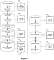
- Figure 4 conceptually illustrates the propagation of data through the hierarchical network control system of some embodiments.
- the left side of this figure shows the data flow to the managed forwarding elements to implement the logical forwarding elements (e.g., the logical switches and logical routers) of the logical network, while the right side of the figure shows the propagation of BGP data to the gateway hosts in order to provision a BGP daemon operating within the L3 gateway.
- the logical forwarding elements e.g., the logical switches and logical routers
- the logical control plane data is converted by the logical controller 310 (specifically, by a control application of the logical controller) to logical forwarding plane data, and then subsequently (by a virtualization application of the logical controller) to universal physical control plane data.
- these conversions generate a flow entry at the logical forwarding plane (or a data tuple that defines a flow entry), then add a match over the logical data path set (e.g., the logical switch or router) at the universal physical control plane.
- the universal physical control plane also includes additional flow entries (or data tuples) for mapping generic physical ingress ports (i.e., a generic abstraction of a port not specific to any particular MFE) to logical ingress ports as well as for mapping logical egress ports to generic physical egress ports.
- generic physical ingress ports i.e., a generic abstraction of a port not specific to any particular MFE
- the flow entries at the universal physical control plane would include a forwarding decision to send a packet to the logical port to which the VM connects when the destination MAC address of the packet matches that of the VM, as well as an egress context mapping entry that maps the logical egress port to a generic physical (i.e., virtual) interface.
- the universal physical control plane data includes a generic tunneling entry for encapsulating the packet in a tunnel to the MFE at which the VM is located.
- the physical controller 315 (one of the several physical controllers in the hierarchical network control system 300), as shown, translates the universal physical control plane data into customized physical control plane data for the particular MFEs that it manages at hosts 325, 330, 345, and 350. This conversion involves substituting specific data (e.g., specific physical ports or tunnel encapsulation information) for the generic abstractions in the universal physical control plane data.
- specific data e.g., specific physical ports or tunnel encapsulation information
- the port integration entries are configured to specify the physical layer port to which the VM attaches (i.e., an identifier for the actual virtual interface).
- the tunnel encapsulation entries for the different MFEs will have different tunnel encapsulation information.
- the MFEs at both of the gateway hosts 345 and 350 perform such a translation in order to forward packets between (i) the L3 gateways, (ii) other network entities (e.g., VMs) within the managed network via tunnels, and (iii) the external network.
- the logical controller 310 Based on this information (i.e., the set of physical routers to which each port connects, the IP addresses/subnets of the VMs/logical switches), the logical controller 310 generates the set of data tuples for the BGP configuration. This may be performed by the table mapping engine in some embodiments, that also converts the logical control plane data into physical control plane data. In addition to the BGP data tuples, the logical controller generates data tuples for the logical router aspect of the L3 gateway (e.g., the routing table). In order to define containers on a particular gateway host, some embodiments define each container as a separate data tuple that specifies the existence of the container and the processes running on the container, including BGP.
- BGP may be enabled. Furthermore, this data tuple defines various BGP options, such as the router ID, whether or not to advertise graceful restart capability, and a list of prefixes (e.g., in classless interdomain routing (CIDR) form) to advertise to all peers.
- the logical controller creates a data tuple for each BGP neighbor (i.e., peer external router) of a particular L3 gateway.
- BGP neighbor i.e., peer external router
- These neighbor data tuples specify, in some embodiments, the address of the BGP neighbor, a keep-alive timer that indicates the time between keep-alive packets, and the interface through which the BGP application in the gateway communicates with the neighbor, among other information.
- a process on the gateway host 345 starts up the container for the L3 gateway and translates the BGP data tuples stored in the database into a BGP configuration file for an application operating in the L3 gateway.
- the application can load the configuration in order to determine its operating configuration.
- some embodiments assign only one gateway per cluster for a particular logical router, while other embodiments assign all gateways for a logical router to the same cluster. Yet other embodiments may assign gateways to several different clusters, but allow two or more gateways within a single cluster.
- the gateway host machines may be assigned to different groups based on the functions for which those gateway hosts are used. For example, within a physical managed network, some embodiments use a first group of gateway hosts for providing logical services (e.g., DHCP, metadata proxy), a second group of gateway hosts for L3 gateways that utilize BGP for route advertisement and for which each logical router port is assigned a single gateway, and a third group of gateway hosts for L3 gateways that do not utilize route advertisement and for which each logical router port is assigned to multiple gateways.
- the controller selects gateway hosts from among the second group for each logical router port. Each group may span several clusters of gateway hosts, thereby allowing for the process 500 to select (at 510) gateway host machines within the second group from several clusters (i.e., failure domains).
- Some embodiments allow the administrator to specify the cluster to which the controller assigns each logical port of the logical router, and the controller handles selection of the actual gateway host within that cluster.
- the administrator might specify to have two logical ports assigned to gateways in a first cluster, four in a second cluster, and two more in a third cluster.
- the controller then assigns each logical port to a specific gateway host in its selected cluster.
- some embodiments use a load balancing technique, such as calculating a hash function of a property of the logical router or port (e.g., a UUID assigned by the controller) modulo the number of gateway hosts in the cluster. This assigns the logical router ports to gateway hosts within the cluster effectively at random (even though the algorithm itself is deterministic), and therefore load balances the L3 gateways across the gateway hosts over the long run.
- Different embodiments handle failover of the L3 gateways implementing the uplink ports differently.
- the network does not immediately replace the L3 gateway on a new host. Instead, the network controller allows the incoming (and, in some embodiments, outgoing) packets to be distributed across the other uplink ports whose gateways are still active.
- some embodiments replace the L3 gateway with a new implementation for the uplink port on a different gateway host (e.g., in the same cluster as the failed host).
- the MFEs will begin sending traffic to the second (standby) host, and the network controller will let the second host know to activate its BGP daemon.
- the failover for high-availability gateways is described in further detail in U.S. Application 14/166,446 , entitled "High Availability L3 Gateways for Logical Networks" and filed January 28, 2014. U.S. Application 14/166,446 .
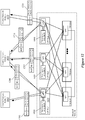
- the controller cluster sends data 1105 to the first gateway host 1035 indicating the prefixes 10.0.0/24 and 10.0.1/24 and two BGP neighbors 15.1.1.1 and 16.1.1.1 (the IP addresses for the two routers with which this gateway interfaces).
- the controller cluster sends data III 0 to the second gateway host 1040 indicating the same two prefixes and only one BGP neighbor 16.1.1.1.
- the controller cluster sends data 1115 to the third gateway host 1045 indicating the same two prefixes and two BGP neighbors 16.1.1.1 and 17.1.1.1.
- the controller cluster transmits this data in the same format as other non-flow entry configuration data for the gateway (e.g., as data tuples transmitted using the OVSDB protocol).
- the BGP configuration data sent from the controller may also include other data such as the autonomous system number (which will be the same across the gateways), router identification info for the gateways, and additional information about the peer routers (e.g., the autonomous system numbers of the peers).
- the namespace 1050 receives the packet, processes it through its IP network stack (including its routing table), and returns the packet to the MFE through a different interface with the MFE.
- the processing pipeline in the namespace may include some or all of network address translation, firewall processing, and routing. Some embodiments, however, do not allow stateful services such as network address translation to be performed on the gateways for distributed logical routers with multiple gateways, due to the difficulty of state sharing.
- the routing performed by the namespace maps the destination IP address to a destination MAC address of the logical router port to which the gateway attaches, in some embodiments. In other embodiments, the routing maps the destination IP address to the destination MAC address of the VM or other entity to which the packet is being sent.
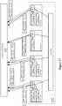
- FIG 17 conceptually illustrates the BGP Update packets sent by the various BGP daemons to the external router 1575, once the daemons running in the various namespaces have established adjacencies with the router. These packets are similar to those described above by reference to Figure 12 . As a result, the router 1575 will have four equal-cost options for packets sent to IP addresses in the ranges 10.0.0/24 and 10.0.1/24, and three equal-cost options for packets sent to IP addresses in the ranges 11.0.0/24 and 11.0.1/24.
- packet refers to several packets of different types.
- packet is used here as well as throughout this application to refer to a collection of bits in a particular format sent across a network.
- packet may be used herein to refer to various formatted collections of bits that may be sent across a network, such as Ethernet frames, TCP segments, UDP datagrams, IP packets, etc.
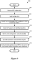
- the controller e.g., the table mapping engine in the controller
- the controller identifies the CIDR prefixes for the logical switches that attach to the logical router, as these are the prefixes that the controller as route server will advertise to the external routers (which will be the same for each gateway).
- the controller uses the selections of gateway host machines for the BGP configuration, and information generated for the namespace that will run on the gateway host machine.
- the BGP process on the controller will send out packets advertising these namespaces (rather than itself) as the actual next hop(s) for the advertised routes, and therefore must be able to provide the requisite data about the namespaces (e.g., the autonomous system number, the router identifier, etc.).
- the controller generates a configuration file, or several configuration files, for the BGP instance(s). These configuration files may be similar to the files generated by the namespace daemon described above.
- the controller stores the configuration files in a location at which the BGP processes can access the files and load their configuration. At this point, the controller can begin acting as a route server to contact the external routers.
- the process 1900 opens (at 1935), or attempts to open, BGP session(s) with the neighbor external routers identified in the configuration.
- BGP session(s) As in the inline model described in the previous section, several BGP sessions are started, each operating as its own independent state machine. For instance, if the logical network includes three ports facing the external network (and thus three gateways), each of which connect to two different external routers, then the controller will initiate six separate BGP sessions in some embodiments. In other embodiments, the controller initiates only one BGP session per external router, and sends Updates that specify the several different next hop options for the routes advertised to the external router.
- This process 1900 assumes that adjacency is established for each BGP session- if the BGP process fails to open a session with a particular router, then the controller continues attempting to do so in some embodiments before transitioning to operation 1940.
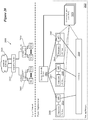
- FIG 21 conceptually illustrates some of the control and data path data sent by the controller cluster 2070 in order to effectuate the logical router 2015.
- the controller cluster 2070 distributes logical router configuration data 2105 (e.g., as data tuples defining routing tables for the namespaces, as flow entries for the MFEs, etc.) to the gateway hosts 2035-2045.
- the controller cluster sends this data in two channels, with the flow entries for the MFE sent via a first protocol (e.g., OpenFlow) and the data tuples defining the namespace and the routing table for the namespace sent via a second protocol (e.g., OVSDB).
- the controller cluster of some embodiments distributes the logical router configuration data 2105 through a hierarchy of controllers, with a single logical controller generating the data and distributing the data to the various physical controllers that manage and directly provide data to the three gateway hosts 2045.
- the interface of some embodiments When the input interface 2305 receives a specification of a logical network, the interface of some embodiments translates this specification into logical control plane data that defines the logical network, and passes this data to the table mapping state computation module 2310. In some embodiments, the input interface 2305 reads this logical control plane data into input tables of the state computation module 2310.
- the table mapping state computation module 2310 of some embodiments includes a table mapping engine with a set of input tables and output tables, and maps records in the input tables to records in the output tables according to a set of rules. More specifically, some embodiments translate logical control plane data into logical forwarding plane data and subsequently translate the logical forwarding plane data into universal or customized physical control plane data that can be passed down to the MFEs that implement the logical network.
- the table mapping state computation module 2310 of some embodiments uses nLog, and is described in greater detail in U.S. Publication 2013/0058228 .
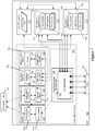
- the controller 2300 distributes data to host machines (both VM hosts and gateway hosts) through its MFE interface 2320. Through this interface, the controller distributes physical control plane data, routing table and configuration data tuples, etc. to the MFEs, L3 gateways, etc. at the host machines.
- the interface is a direct connection to the host machines, while in other embodiments the controller 2300 is a logical controller that distributes the generated data to a set of physical controllers.
- the controller uses this interface to distribute BGP configuration data tuples.
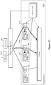
- FIG. 24 conceptually illustrates such a managed network 2400 of some embodiments within which a logical network (similar in structure to that of Figure 1 or Figure 10 ) is implemented, and which uses a separate gateway as a route server. For simplicity, this figure does not illustrate the host machines upon which the VMs attached to the logical network reside.
- the logical router has three ports connecting to the external network, and therefore these ports are implemented on three gateways 2405-2415, in three namespaces 2420-2430. These namespaces operate as L3 gateways to handle ingress and egress traffic, but do not operate a routing protocol application, and therefore do not exchange data with the external network router 2435. Instead, the controller selects a fourth gateway host 2440 to operate as a route server for the logical network.
- a namespace 2445 operates on the gateway host 2440, running a BGP daemon similar to those shown above in Section II.
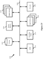
- the processing unit(s) 2510 retrieve instructions to execute and data to process in order to execute the processes of the invention.
- the processing unit(s) may be a single processor or a multi-core processor in different embodiments.
- the read-only-memory (ROM) 2530 stores static data and instructions that are needed by the processing unit(s) 2510 and other modules of the electronic system.
- the permanent storage device 2535 is a read-and-write memory device. This device is a non-volatile memory unit that stores instructions and data even when the electronic system 2500 is off. Some embodiments of the invention use a mass-storage device (such as a magnetic or optical disk and its corresponding disk drive) as the permanent storage device 2535.
- the bus 2505 also connects to the input and output devices 2540 and 2545.
- the input devices enable the user to communicate information and select commands to the electronic system.
- the input devices 2540 include alphanumeric keyboards and pointing devices (also called “cursor control devices").
- the output devices 2545 display images generated by the electronic system.
- the output devices include printers and display devices, such as cathode ray tubes (CRT) or liquid crystal displays (LCD). Some embodiments include devices such as a touchscreen that function as both input and output devices.
- CTR cathode ray tubes
- LCD liquid crystal displays
- Some embodiments include electronic components, such as microprocessors, storage and memory that store computer program instructions in a machine-readable or computer-readable medium (alternatively referred to as computer-readable storage media, machine-readable media, or machine-readable storage media).
- computer-readable media include RAM, ROM, read-only compact discs (CD-ROM), recordable compact discs (CD-R), rewritable compact discs (CD-RW), read-only digital versatile discs (e.g., DVD- ROM, dual-layer DVD-ROM), a variety of recordable/rewritable DVDs (e.g., DVD-RAM, DVD-RW, DVD+RW, etc.), flash memory (e.g., SD cards, mini-SD cards, micro-SD cards, etc.), magnetic and/or solid state hard drives, read-only and recordable Blu-Ray® discs, ultra density optical discs, any other optical or magnetic media, and floppy disks.
- CD-ROM compact discs
- CD-R recordable compact discs
Landscapes
- Engineering & Computer Science (AREA)
- Computer Networks & Wireless Communication (AREA)
- Signal Processing (AREA)
- Software Systems (AREA)
- Theoretical Computer Science (AREA)
- Physics & Mathematics (AREA)
- General Engineering & Computer Science (AREA)
- General Physics & Mathematics (AREA)
- Data Exchanges In Wide-Area Networks (AREA)
Claims (13)
- Procédé destiné à un contrôleur de réseau (310) qui gère une pluralité de réseaux logiques, le procédé comprenant :la réception d'une spécification d'un réseau logique (1000) de la pluralité de réseaux logiques, le réseau logique (1000) comprenant un élément de transfert logique (1015) comportant au moins deux ports logiques qui connectent chacun le réseau logique à un réseau externe (1020) et qui s'apparient chacun avec au moins un routeur physique (1065-1075) du réseau externe (1020) afin de signaler des informations de possibilité d'atteindre une adresse de réseau pour au moins deux sous-réseaux du réseau logique au réseau externe (1020), dans lequel un premier port logique s'apparie avec un premier routeur physique (1065) sur un premier sous-réseau du réseau externe et un second port logique s'apparie avec un second routeur physique (1070) sur un second sous-réseau du réseau externe (1020), dans lequel les premier et second sous-réseaux sont différents l'un de l'autre et des au moins deux sous-réseaux du réseau logique (1000) ;la sélection de machines hôtes (1035-1045) parmi une pluralité de machines hôtes pour héberger des passerelles (1050-1060) destinées à mettre en œuvre chacun des ports logiques qui connectent le réseau logique (1000) au réseau externe (1020) ; etla génération, pour la distribution à chacune des passerelles (1050-1060), d'uplets de données définissant (i) une table d'acheminement destinée à mettre en œuvre la connexion entre le réseau logique (1000) et le réseau externe (1020) pour le port mis en œuvre par la passerelle et (ii) une configuration pour une application de protocole d'acheminement qui permet à la passerelle de s'apparier avec le routeur physique (1065-1075) du réseau externe (1020) avec lequel s'apparie le port mis en œuvre par la passerelle.
- Procédé selon la revendication 1, dans lequel les uplets de données définissant la configuration pour l'application de protocole d'acheminement pour la passerelle (1050) mettant en œuvre le premier port logique comprennent une adresse de réseau, un numéro de système autonome, un temps d'entretien et un minuteur de maintien pour le premier routeur physique (1065) du réseau externe.
- Procédé selon la revendication 1, dans lequel la sélection des machines hôtes (1035-1045) pour héberger les passerelles (1050-1060) pour mettre en œuvre chacun des ports logiques qui connectent le réseau logique (1000) au réseau externe (1020) comprend la sélection d'une machine hôte (1035-1045) différente parmi la pluralité de machines hôtes pour mettre en œuvre chacun des ports logiques.
- Procédé selon la revendication 1, dans lequel les uplets de données définissant la configuration pour l'application de protocole d'acheminement pour la passerelle (1050) mettant en œuvre le premier port logique comprennent des données relatives à une pluralité de routeurs physiques (1065-1070) avec lesquels s'apparie le premier port logique.
- Procédé selon la revendication 1, dans lequel les uplets de données définissant la configuration pour l'application de protocole d'acheminement pour une passerelle particulière comprennent un numéro de système autonome local, un identifiant de routeur et une liste d'adresses de réseau à signaler comme pouvant être atteintes par l'intermédiaire de la passerelle particulière.
- Procédé selon la revendication 1, dans lequel l'élément de transfert logique est un routeur logique (1015), dans lequel chacun des au moins deux sous-réseaux du réseau logique correspond à un commutateur logique (1005-1010) différent qui se connecte au routeur logique (1015) .
- Procédé selon la revendication 1, dans lequel le réseau logique (1000) est mis en œuvre par une pluralité d'éléments de transfert gérés fonctionnant sur une seconde pluralité de machines hôtes (1030).
- Procédé selon la revendication 1, dans lequel la seconde pluralité de machines hôtes (1030) héberge des machines virtuelles qui se connectent aux commutateurs logiques (1005-1010) du réseau logique (1000).
- Procédé selon la revendication 1, dans lequel chacune des passerelles (1050-1060) est mise en œuvre dans un conteneur virtuel fonctionnant sur sa machine hôte respective.
- Procédé selon la revendication 1, dans lequel l'application de protocole d'acheminement pour la passerelle (1050) mettant en œuvre le premier port logique utilise le protocole de passerelle frontière (BGP) pour établir une contiguïté avec le premier routeur physique (1065).
- Procédé selon la revendication 1, dans lequel un démon fonctionnant sur la machine hôte (1035) sélectionnée pour la passerelle (1050) mettant en œuvre le premier port logique reçoit les uplets de données définissant la configuration pour l'application de protocole d'acheminement de la passerelle et convertit les uplets de données en un fichier de configuration pour l'application de protocole d'acheminement.
- Support lisible par machine stockant un programme qui, lorsqu'il est exécuté par au moins une unité de traitement, exécute toutes les étapes du procédé selon l'une quelconque des revendications 1 à 11.
- Ordinateur comprenant :un ensemble d'unités de traitement ; etun support lisible par machine stockant un programme qui, lorsqu'il est exécuté par au moins l'une des unités de traitement, exécute toutes les étapes du procédé selon l'une quelconque des revendications 1 à 11.
Applications Claiming Priority (4)
| Application Number | Priority Date | Filing Date | Title |
|---|---|---|---|
| US14/214,553 US9225597B2 (en) | 2014-03-14 | 2014-03-14 | Managed gateways peering with external router to attract ingress packets |
| US14/214,561 US9590901B2 (en) | 2014-03-14 | 2014-03-14 | Route advertisement by managed gateways |
| PCT/US2014/072875 WO2015138043A2 (fr) | 2014-03-14 | 2014-12-30 | Annonce de route par des passerelles gérées |
| EP14844975.4A EP3117561B1 (fr) | 2014-03-14 | 2014-12-30 | Annonce de route par des passerelles gérées |
Related Parent Applications (2)
| Application Number | Title | Priority Date | Filing Date |
|---|---|---|---|
| EP14844975.4A Division-Into EP3117561B1 (fr) | 2014-03-14 | 2014-12-30 | Annonce de route par des passerelles gérées |
| EP14844975.4A Division EP3117561B1 (fr) | 2014-03-14 | 2014-12-30 | Annonce de route par des passerelles gérées |
Publications (2)
| Publication Number | Publication Date |
|---|---|
| EP3435596A1 EP3435596A1 (fr) | 2019-01-30 |
| EP3435596B1 true EP3435596B1 (fr) | 2020-04-15 |
Family
ID=52672316
Family Applications (2)
| Application Number | Title | Priority Date | Filing Date |
|---|---|---|---|
| EP18194211.1A Active EP3435596B1 (fr) | 2014-03-14 | 2014-12-30 | Publicité pour un itinéraire par des passerelles gérées |
| EP14844975.4A Active EP3117561B1 (fr) | 2014-03-14 | 2014-12-30 | Annonce de route par des passerelles gérées |
Family Applications After (1)
| Application Number | Title | Priority Date | Filing Date |
|---|---|---|---|
| EP14844975.4A Active EP3117561B1 (fr) | 2014-03-14 | 2014-12-30 | Annonce de route par des passerelles gérées |
Country Status (3)
| Country | Link |
|---|---|
| EP (2) | EP3435596B1 (fr) |
| CN (3) | CN106134137B (fr) |
| WO (1) | WO2015138043A2 (fr) |
Families Citing this family (31)
| Publication number | Priority date | Publication date | Assignee | Title |
|---|---|---|---|---|
| US9225638B2 (en) | 2013-05-09 | 2015-12-29 | Vmware, Inc. | Method and system for service switching using service tags |
| US9577845B2 (en) | 2013-09-04 | 2017-02-21 | Nicira, Inc. | Multiple active L3 gateways for logical networks |
| US9590901B2 (en) | 2014-03-14 | 2017-03-07 | Nicira, Inc. | Route advertisement by managed gateways |
| US10135737B2 (en) | 2014-09-30 | 2018-11-20 | Nicira, Inc. | Distributed load balancing systems |
| US10038628B2 (en) | 2015-04-04 | 2018-07-31 | Nicira, Inc. | Route server mode for dynamic routing between logical and physical networks |
| US10333849B2 (en) | 2016-04-28 | 2019-06-25 | Nicira, Inc. | Automatic configuration of logical routers on edge nodes |
| US10091161B2 (en) | 2016-04-30 | 2018-10-02 | Nicira, Inc. | Assignment of router ID for logical routers |
| US10560320B2 (en) | 2016-06-29 | 2020-02-11 | Nicira, Inc. | Ranking of gateways in cluster |
| US10756928B2 (en) | 2016-07-29 | 2020-08-25 | At&T Intellectual Property I, L.P. | Interconnection between enterprise network customers and network-based cloud service providers |
| US10237123B2 (en) | 2016-12-21 | 2019-03-19 | Nicira, Inc. | Dynamic recovery from a split-brain failure in edge nodes |
| US10616045B2 (en) | 2016-12-22 | 2020-04-07 | Nicira, Inc. | Migration of centralized routing components of logical router |
| US10805181B2 (en) | 2017-10-29 | 2020-10-13 | Nicira, Inc. | Service operation chaining |
| US10805192B2 (en) | 2018-03-27 | 2020-10-13 | Nicira, Inc. | Detecting failure of layer 2 service using broadcast messages |
| CN110198266B (zh) * | 2018-07-31 | 2021-12-10 | 腾讯科技(深圳)有限公司 | 实时数据流处理方法及系统 |
| EP3815312A1 (fr) * | 2018-09-02 | 2021-05-05 | VMware, Inc. | Insertion de service au niveau d'une passerelle de réseau logique |
| US11595250B2 (en) | 2018-09-02 | 2023-02-28 | Vmware, Inc. | Service insertion at logical network gateway |
| CN111510383B (zh) * | 2019-01-31 | 2023-03-24 | 华为技术有限公司 | 一种路由计算方法以及相关设备 |
| US11086654B2 (en) | 2019-02-22 | 2021-08-10 | Vmware, Inc. | Providing services by using multiple service planes |
| US11140218B2 (en) | 2019-10-30 | 2021-10-05 | Vmware, Inc. | Distributed service chain across multiple clouds |
| US11223494B2 (en) | 2020-01-13 | 2022-01-11 | Vmware, Inc. | Service insertion for multicast traffic at boundary |
| CN111371678B (zh) * | 2020-02-26 | 2021-12-31 | 北京天维信通科技有限公司 | 第三方服务运行方法和装置、网关设备及存储介质 |
| CN111464370B (zh) * | 2020-05-18 | 2021-05-25 | 珠海格力电器股份有限公司 | 一种配网装置、物联网控制系统及其配网方法 |
| CN116057909B (zh) * | 2020-07-28 | 2025-10-10 | 威睿有限责任公司 | 支持分布式网关服务体系架构的路由公告 |
| CN114157668B (zh) * | 2020-08-17 | 2023-11-17 | 中国电信股份有限公司 | 多租户跨集群的组网方法、通信系统和可读存储介质 |
| CN112367257B (zh) * | 2020-10-30 | 2022-10-21 | 新华三技术有限公司 | 路由通告方法及装置 |
| CN114567580B (zh) * | 2020-11-27 | 2023-10-20 | 华为技术有限公司 | 一种消息发送方法、消息处理方法、装置及系统 |
| US11734043B2 (en) | 2020-12-15 | 2023-08-22 | Vmware, Inc. | Providing stateful services in a scalable manner for machines executing on host computers |
| US11528224B1 (en) * | 2021-10-15 | 2022-12-13 | Hewlett Packard Enterprise Development Lp | Dynamic traffic redirection for a virtual gateway of a distributed tunnel fabric |
| GB202202807D0 (en) * | 2022-03-01 | 2022-04-13 | Graphcore Ltd | A computer system |
| CN117097591B (zh) * | 2023-10-19 | 2024-01-23 | 四川中电启明星信息技术有限公司 | 一种应用安全接入网关系统及路由转发方法 |
| CN117498994B (zh) * | 2023-11-16 | 2024-05-24 | 浪潮智慧科技有限公司 | 一种微服务架构的资源请求方法及设备 |
Family Cites Families (22)
| Publication number | Priority date | Publication date | Assignee | Title |
|---|---|---|---|---|
| US7209435B1 (en) * | 2002-04-16 | 2007-04-24 | Foundry Networks, Inc. | System and method for providing network route redundancy across Layer 2 devices |
| US7974311B2 (en) * | 2004-02-10 | 2011-07-05 | Spyder Navigations L.L.C. | Configuring addresses in a communication network |
| GB2419703A (en) * | 2004-10-29 | 2006-05-03 | Hewlett Packard Development Co | Isolated virtual overlay infrastructures each having an interface to control interaction with others |
| US7990888B2 (en) * | 2005-03-04 | 2011-08-02 | Cisco Technology, Inc. | System and methods for network reachability detection |
| US9210034B2 (en) * | 2007-03-01 | 2015-12-08 | Cisco Technology, Inc. | Client addressing and roaming in a wireless network |
| CN101018159A (zh) * | 2007-03-12 | 2007-08-15 | 杭州华为三康技术有限公司 | 多网关环境下负载均衡的方法及dhcp服务器 |
| US20080259797A1 (en) * | 2007-04-18 | 2008-10-23 | Aladdin Knowledge Systems Ltd. | Load-Balancing Bridge Cluster For Network Nodes |
| US8547844B2 (en) * | 2007-07-10 | 2013-10-01 | Telefonaktiebolaget L M Ericsson (Publ) | System and method for balancing IP gateway services |
| US8014278B1 (en) * | 2007-12-17 | 2011-09-06 | Force 10 Networks, Inc | Adaptive load balancing between ECMP or LAG port group members |
| CN102215158B (zh) * | 2010-04-08 | 2015-04-15 | 杭州华三通信技术有限公司 | 实现vrrp流量传输的方法和路由设备 |
| US8345692B2 (en) * | 2010-04-27 | 2013-01-01 | Cisco Technology, Inc. | Virtual switching overlay for cloud computing |
| US8407366B2 (en) * | 2010-05-14 | 2013-03-26 | Microsoft Corporation | Interconnecting members of a virtual network |
| US8718070B2 (en) | 2010-07-06 | 2014-05-06 | Nicira, Inc. | Distributed network virtualization apparatus and method |
| US8363656B2 (en) * | 2010-09-15 | 2013-01-29 | International Business Machines Corporation | Multiple virtual machines sharing a single IP address |
| EP2515507A1 (fr) * | 2011-04-19 | 2012-10-24 | Siemens Aktiengesellschaft | Configuration automatique de dispositifs de réseau |
| CN103534987B (zh) * | 2011-06-07 | 2016-05-04 | 国际商业机器公司 | 用于配置虚拟网络配置的方法和系统 |
| CN107071088B (zh) * | 2011-08-17 | 2020-06-05 | Nicira股份有限公司 | 逻辑l3路由 |
| EP2748716B1 (fr) * | 2011-11-15 | 2018-05-16 | Nicira Inc. | Système de commande de réseau pour configuration de boîtiers intermédiaires |
| CN102594664B (zh) * | 2012-02-02 | 2015-06-17 | 杭州华三通信技术有限公司 | 流量转发方法和装置 |
| US20130305344A1 (en) * | 2012-05-14 | 2013-11-14 | Alcatel-Lucent India Limited | Enterprise network services over distributed clouds |
| CN103346900B (zh) * | 2013-05-31 | 2016-12-28 | 华为技术有限公司 | 大二层网络中虚拟机热迁移后的路由配置方法和网关 |
| CN103607432B (zh) * | 2013-10-30 | 2019-08-27 | 南京中兴软件有限责任公司 | 一种网络创建的方法和系统及网络控制中心 |
-
2014
- 2014-12-30 EP EP18194211.1A patent/EP3435596B1/fr active Active
- 2014-12-30 CN CN201480077752.6A patent/CN106134137B/zh active Active
- 2014-12-30 CN CN202210558749.2A patent/CN114726786B/zh active Active
- 2014-12-30 EP EP14844975.4A patent/EP3117561B1/fr active Active
- 2014-12-30 CN CN202010257206.8A patent/CN111478852B/zh active Active
- 2014-12-30 WO PCT/US2014/072875 patent/WO2015138043A2/fr not_active Ceased
Non-Patent Citations (1)
| Title |
|---|
| None * |
Also Published As
| Publication number | Publication date |
|---|---|
| WO2015138043A2 (fr) | 2015-09-17 |
| EP3117561B1 (fr) | 2018-10-17 |
| EP3117561A2 (fr) | 2017-01-18 |
| CN111478852A (zh) | 2020-07-31 |
| WO2015138043A3 (fr) | 2015-11-19 |
| CN106134137A (zh) | 2016-11-16 |
| CN114726786A (zh) | 2022-07-08 |
| CN106134137B (zh) | 2020-04-17 |
| CN114726786B (zh) | 2024-06-21 |
| CN111478852B (zh) | 2022-05-24 |
| EP3435596A1 (fr) | 2019-01-30 |
Similar Documents
| Publication | Publication Date | Title |
|---|---|---|
| US20240380696A1 (en) | Route advertisement by managed gateways | |
| EP3435596B1 (fr) | Publicité pour un itinéraire par des passerelles gérées | |
| US9225597B2 (en) | Managed gateways peering with external router to attract ingress packets | |
| US12074731B2 (en) | Transitive routing in public cloud | |
| US10389634B2 (en) | Multiple active L3 gateways for logical networks | |
| EP3815311B1 (fr) | Utilisation intelligente d'appairage dans un nuage public | |
| US11196591B2 (en) | Centralized overlay gateway in public cloud | |
| US9503371B2 (en) | High availability L3 gateways for logical networks | |
| US12003424B2 (en) | Load balancing communication sessions in a networked computing environment | |
| US20150058463A1 (en) | Proxy methods for suppressing broadcast traffic in a network | |
| US20250071021A1 (en) | Configuring components of a software-defined network to automatically deploy and monitor logical edge routers for users |
Legal Events
| Date | Code | Title | Description |
|---|---|---|---|
| PUAI | Public reference made under article 153(3) epc to a published international application that has entered the european phase |
Free format text: ORIGINAL CODE: 0009012 |
|
| STAA | Information on the status of an ep patent application or granted ep patent |
Free format text: STATUS: THE APPLICATION HAS BEEN PUBLISHED |
|
| AC | Divisional application: reference to earlier application |
Ref document number: 3117561 Country of ref document: EP Kind code of ref document: P |
|
| AK | Designated contracting states |
Kind code of ref document: A1 Designated state(s): AL AT BE BG CH CY CZ DE DK EE ES FI FR GB GR HR HU IE IS IT LI LT LU LV MC MK MT NL NO PL PT RO RS SE SI SK SM TR |
|
| STAA | Information on the status of an ep patent application or granted ep patent |
Free format text: STATUS: REQUEST FOR EXAMINATION WAS MADE |
|
| 17P | Request for examination filed |
Effective date: 20190723 |
|
| RBV | Designated contracting states (corrected) |
Designated state(s): AL AT BE BG CH CY CZ DE DK EE ES FI FR GB GR HR HU IE IS IT LI LT LU LV MC MK MT NL NO PL PT RO RS SE SI SK SM TR |
|
| GRAP | Despatch of communication of intention to grant a patent |
Free format text: ORIGINAL CODE: EPIDOSNIGR1 |
|
| STAA | Information on the status of an ep patent application or granted ep patent |
Free format text: STATUS: GRANT OF PATENT IS INTENDED |
|
| RIC1 | Information provided on ipc code assigned before grant |
Ipc: H04L 12/24 20060101AFI20191018BHEP Ipc: H04L 12/715 20130101ALI20191018BHEP |
|
| INTG | Intention to grant announced |
Effective date: 20191111 |
|
| GRAS | Grant fee paid |
Free format text: ORIGINAL CODE: EPIDOSNIGR3 |
|
| GRAA | (expected) grant |
Free format text: ORIGINAL CODE: 0009210 |
|
| STAA | Information on the status of an ep patent application or granted ep patent |
Free format text: STATUS: THE PATENT HAS BEEN GRANTED |
|
| AC | Divisional application: reference to earlier application |
Ref document number: 3117561 Country of ref document: EP Kind code of ref document: P |
|
| AK | Designated contracting states |
Kind code of ref document: B1 Designated state(s): AL AT BE BG CH CY CZ DE DK EE ES FI FR GB GR HR HU IE IS IT LI LT LU LV MC MK MT NL NO PL PT RO RS SE SI SK SM TR |
|
| REG | Reference to a national code |
Ref country code: CH Ref legal event code: EP |
|
| REG | Reference to a national code |
Ref country code: DE Ref legal event code: R096 Ref document number: 602014063987 Country of ref document: DE |
|
| REG | Reference to a national code |
Ref country code: IE Ref legal event code: FG4D |
|
| REG | Reference to a national code |
Ref country code: AT Ref legal event code: REF Ref document number: 1258594 Country of ref document: AT Kind code of ref document: T Effective date: 20200515 |
|
| REG | Reference to a national code |
Ref country code: NL Ref legal event code: MP Effective date: 20200415 |
|
| REG | Reference to a national code |
Ref country code: LT Ref legal event code: MG4D |
|
| PG25 | Lapsed in a contracting state [announced via postgrant information from national office to epo] |
Ref country code: LT Free format text: LAPSE BECAUSE OF FAILURE TO SUBMIT A TRANSLATION OF THE DESCRIPTION OR TO PAY THE FEE WITHIN THE PRESCRIBED TIME-LIMIT Effective date: 20200415 Ref country code: IS Free format text: LAPSE BECAUSE OF FAILURE TO SUBMIT A TRANSLATION OF THE DESCRIPTION OR TO PAY THE FEE WITHIN THE PRESCRIBED TIME-LIMIT Effective date: 20200815 Ref country code: NO Free format text: LAPSE BECAUSE OF FAILURE TO SUBMIT A TRANSLATION OF THE DESCRIPTION OR TO PAY THE FEE WITHIN THE PRESCRIBED TIME-LIMIT Effective date: 20200715 Ref country code: GR Free format text: LAPSE BECAUSE OF FAILURE TO SUBMIT A TRANSLATION OF THE DESCRIPTION OR TO PAY THE FEE WITHIN THE PRESCRIBED TIME-LIMIT Effective date: 20200716 Ref country code: FI Free format text: LAPSE BECAUSE OF FAILURE TO SUBMIT A TRANSLATION OF THE DESCRIPTION OR TO PAY THE FEE WITHIN THE PRESCRIBED TIME-LIMIT Effective date: 20200415 Ref country code: PT Free format text: LAPSE BECAUSE OF FAILURE TO SUBMIT A TRANSLATION OF THE DESCRIPTION OR TO PAY THE FEE WITHIN THE PRESCRIBED TIME-LIMIT Effective date: 20200817 Ref country code: SE Free format text: LAPSE BECAUSE OF FAILURE TO SUBMIT A TRANSLATION OF THE DESCRIPTION OR TO PAY THE FEE WITHIN THE PRESCRIBED TIME-LIMIT Effective date: 20200415 Ref country code: NL Free format text: LAPSE BECAUSE OF FAILURE TO SUBMIT A TRANSLATION OF THE DESCRIPTION OR TO PAY THE FEE WITHIN THE PRESCRIBED TIME-LIMIT Effective date: 20200415 |
|
| REG | Reference to a national code |
Ref country code: AT Ref legal event code: MK05 Ref document number: 1258594 Country of ref document: AT Kind code of ref document: T Effective date: 20200415 |
|
| PG25 | Lapsed in a contracting state [announced via postgrant information from national office to epo] |
Ref country code: HR Free format text: LAPSE BECAUSE OF FAILURE TO SUBMIT A TRANSLATION OF THE DESCRIPTION OR TO PAY THE FEE WITHIN THE PRESCRIBED TIME-LIMIT Effective date: 20200415 Ref country code: BG Free format text: LAPSE BECAUSE OF FAILURE TO SUBMIT A TRANSLATION OF THE DESCRIPTION OR TO PAY THE FEE WITHIN THE PRESCRIBED TIME-LIMIT Effective date: 20200715 Ref country code: RS Free format text: LAPSE BECAUSE OF FAILURE TO SUBMIT A TRANSLATION OF THE DESCRIPTION OR TO PAY THE FEE WITHIN THE PRESCRIBED TIME-LIMIT Effective date: 20200415 Ref country code: LV Free format text: LAPSE BECAUSE OF FAILURE TO SUBMIT A TRANSLATION OF THE DESCRIPTION OR TO PAY THE FEE WITHIN THE PRESCRIBED TIME-LIMIT Effective date: 20200415 |
|
| PG25 | Lapsed in a contracting state [announced via postgrant information from national office to epo] |
Ref country code: AL Free format text: LAPSE BECAUSE OF FAILURE TO SUBMIT A TRANSLATION OF THE DESCRIPTION OR TO PAY THE FEE WITHIN THE PRESCRIBED TIME-LIMIT Effective date: 20200415 |
|
| REG | Reference to a national code |
Ref country code: DE Ref legal event code: R097 Ref document number: 602014063987 Country of ref document: DE |
|
| PG25 | Lapsed in a contracting state [announced via postgrant information from national office to epo] |
Ref country code: ES Free format text: LAPSE BECAUSE OF FAILURE TO SUBMIT A TRANSLATION OF THE DESCRIPTION OR TO PAY THE FEE WITHIN THE PRESCRIBED TIME-LIMIT Effective date: 20200415 Ref country code: DK Free format text: LAPSE BECAUSE OF FAILURE TO SUBMIT A TRANSLATION OF THE DESCRIPTION OR TO PAY THE FEE WITHIN THE PRESCRIBED TIME-LIMIT Effective date: 20200415 Ref country code: AT Free format text: LAPSE BECAUSE OF FAILURE TO SUBMIT A TRANSLATION OF THE DESCRIPTION OR TO PAY THE FEE WITHIN THE PRESCRIBED TIME-LIMIT Effective date: 20200415 Ref country code: EE Free format text: LAPSE BECAUSE OF FAILURE TO SUBMIT A TRANSLATION OF THE DESCRIPTION OR TO PAY THE FEE WITHIN THE PRESCRIBED TIME-LIMIT Effective date: 20200415 Ref country code: SM Free format text: LAPSE BECAUSE OF FAILURE TO SUBMIT A TRANSLATION OF THE DESCRIPTION OR TO PAY THE FEE WITHIN THE PRESCRIBED TIME-LIMIT Effective date: 20200415 Ref country code: CZ Free format text: LAPSE BECAUSE OF FAILURE TO SUBMIT A TRANSLATION OF THE DESCRIPTION OR TO PAY THE FEE WITHIN THE PRESCRIBED TIME-LIMIT Effective date: 20200415 Ref country code: RO Free format text: LAPSE BECAUSE OF FAILURE TO SUBMIT A TRANSLATION OF THE DESCRIPTION OR TO PAY THE FEE WITHIN THE PRESCRIBED TIME-LIMIT Effective date: 20200415 Ref country code: IT Free format text: LAPSE BECAUSE OF FAILURE TO SUBMIT A TRANSLATION OF THE DESCRIPTION OR TO PAY THE FEE WITHIN THE PRESCRIBED TIME-LIMIT Effective date: 20200415 |
|
| PLBE | No opposition filed within time limit |
Free format text: ORIGINAL CODE: 0009261 |
|
| STAA | Information on the status of an ep patent application or granted ep patent |
Free format text: STATUS: NO OPPOSITION FILED WITHIN TIME LIMIT |
|
| PG25 | Lapsed in a contracting state [announced via postgrant information from national office to epo] |
Ref country code: SK Free format text: LAPSE BECAUSE OF FAILURE TO SUBMIT A TRANSLATION OF THE DESCRIPTION OR TO PAY THE FEE WITHIN THE PRESCRIBED TIME-LIMIT Effective date: 20200415 Ref country code: PL Free format text: LAPSE BECAUSE OF FAILURE TO SUBMIT A TRANSLATION OF THE DESCRIPTION OR TO PAY THE FEE WITHIN THE PRESCRIBED TIME-LIMIT Effective date: 20200415 |
|
| 26N | No opposition filed |
Effective date: 20210118 |
|
| PG25 | Lapsed in a contracting state [announced via postgrant information from national office to epo] |
Ref country code: SI Free format text: LAPSE BECAUSE OF FAILURE TO SUBMIT A TRANSLATION OF THE DESCRIPTION OR TO PAY THE FEE WITHIN THE PRESCRIBED TIME-LIMIT Effective date: 20200415 |
|
| REG | Reference to a national code |
Ref country code: CH Ref legal event code: PL |
|
| PG25 | Lapsed in a contracting state [announced via postgrant information from national office to epo] |
Ref country code: MC Free format text: LAPSE BECAUSE OF FAILURE TO SUBMIT A TRANSLATION OF THE DESCRIPTION OR TO PAY THE FEE WITHIN THE PRESCRIBED TIME-LIMIT Effective date: 20200415 |
|
| REG | Reference to a national code |
Ref country code: BE Ref legal event code: MM Effective date: 20201231 |
|
| PG25 | Lapsed in a contracting state [announced via postgrant information from national office to epo] |
Ref country code: LU Free format text: LAPSE BECAUSE OF NON-PAYMENT OF DUE FEES Effective date: 20201230 Ref country code: IE Free format text: LAPSE BECAUSE OF NON-PAYMENT OF DUE FEES Effective date: 20201230 |
|
| REG | Reference to a national code |
Ref country code: DE Ref legal event code: R079 Ref document number: 602014063987 Country of ref document: DE Free format text: PREVIOUS MAIN CLASS: H04L0012240000 Ipc: H04L0041000000 |
|
| PG25 | Lapsed in a contracting state [announced via postgrant information from national office to epo] |
Ref country code: CH Free format text: LAPSE BECAUSE OF NON-PAYMENT OF DUE FEES Effective date: 20201231 Ref country code: LI Free format text: LAPSE BECAUSE OF NON-PAYMENT OF DUE FEES Effective date: 20201231 |
|
| PG25 | Lapsed in a contracting state [announced via postgrant information from national office to epo] |
Ref country code: TR Free format text: LAPSE BECAUSE OF FAILURE TO SUBMIT A TRANSLATION OF THE DESCRIPTION OR TO PAY THE FEE WITHIN THE PRESCRIBED TIME-LIMIT Effective date: 20200415 Ref country code: MT Free format text: LAPSE BECAUSE OF FAILURE TO SUBMIT A TRANSLATION OF THE DESCRIPTION OR TO PAY THE FEE WITHIN THE PRESCRIBED TIME-LIMIT Effective date: 20200415 Ref country code: CY Free format text: LAPSE BECAUSE OF FAILURE TO SUBMIT A TRANSLATION OF THE DESCRIPTION OR TO PAY THE FEE WITHIN THE PRESCRIBED TIME-LIMIT Effective date: 20200415 |
|
| PG25 | Lapsed in a contracting state [announced via postgrant information from national office to epo] |
Ref country code: MK Free format text: LAPSE BECAUSE OF FAILURE TO SUBMIT A TRANSLATION OF THE DESCRIPTION OR TO PAY THE FEE WITHIN THE PRESCRIBED TIME-LIMIT Effective date: 20200415 |
|
| PG25 | Lapsed in a contracting state [announced via postgrant information from national office to epo] |
Ref country code: BE Free format text: LAPSE BECAUSE OF NON-PAYMENT OF DUE FEES Effective date: 20201231 |
|
| REG | Reference to a national code |
Ref country code: DE Ref legal event code: R081 Ref document number: 602014063987 Country of ref document: DE Owner name: VMWARE LLC, PALO ALTO, US Free format text: FORMER OWNER: NICIRA, INC., PALO ALTO, CALIF., US |
|
| REG | Reference to a national code |
Ref country code: GB Ref legal event code: 732E Free format text: REGISTERED BETWEEN 20250220 AND 20250226 |
|
| PGFP | Annual fee paid to national office [announced via postgrant information from national office to epo] |
Ref country code: DE Payment date: 20251210 Year of fee payment: 12 |
|
| PGFP | Annual fee paid to national office [announced via postgrant information from national office to epo] |
Ref country code: GB Payment date: 20251120 Year of fee payment: 12 |
|
| PGFP | Annual fee paid to national office [announced via postgrant information from national office to epo] |
Ref country code: FR Payment date: 20251120 Year of fee payment: 12 |