EP3436144B1 - Wärmeaustauschmodul und -system für medizinische anwendungen - Google Patents
Wärmeaustauschmodul und -system für medizinische anwendungen Download PDFInfo
- Publication number
- EP3436144B1 EP3436144B1 EP16897277.6A EP16897277A EP3436144B1 EP 3436144 B1 EP3436144 B1 EP 3436144B1 EP 16897277 A EP16897277 A EP 16897277A EP 3436144 B1 EP3436144 B1 EP 3436144B1
- Authority
- EP
- European Patent Office
- Prior art keywords
- heat exchange
- exchange module
- heat
- thermally conductive
- thermally
- Prior art date
- Legal status (The legal status is an assumption and is not a legal conclusion. Google has not performed a legal analysis and makes no representation as to the accuracy of the status listed.)
- Active
Links
Images
















Classifications
-
- A—HUMAN NECESSITIES
- A61—MEDICAL OR VETERINARY SCIENCE; HYGIENE
- A61F—FILTERS IMPLANTABLE INTO BLOOD VESSELS; PROSTHESES; DEVICES PROVIDING PATENCY TO, OR PREVENTING COLLAPSING OF, TUBULAR STRUCTURES OF THE BODY, e.g. STENTS; ORTHOPAEDIC, NURSING OR CONTRACEPTIVE DEVICES; FOMENTATION; TREATMENT OR PROTECTION OF EYES OR EARS; BANDAGES, DRESSINGS OR ABSORBENT PADS; FIRST-AID KITS
- A61F7/00—Heating or cooling appliances for medical or therapeutic treatment of the human body
- A61F7/0053—Cabins, rooms, chairs or units for treatment with a hot or cold circulating fluid
-
- A—HUMAN NECESSITIES
- A61—MEDICAL OR VETERINARY SCIENCE; HYGIENE
- A61F—FILTERS IMPLANTABLE INTO BLOOD VESSELS; PROSTHESES; DEVICES PROVIDING PATENCY TO, OR PREVENTING COLLAPSING OF, TUBULAR STRUCTURES OF THE BODY, e.g. STENTS; ORTHOPAEDIC, NURSING OR CONTRACEPTIVE DEVICES; FOMENTATION; TREATMENT OR PROTECTION OF EYES OR EARS; BANDAGES, DRESSINGS OR ABSORBENT PADS; FIRST-AID KITS
- A61F7/00—Heating or cooling appliances for medical or therapeutic treatment of the human body
- A61F7/007—Heating or cooling appliances for medical or therapeutic treatment of the human body characterised by electric heating
-
- A—HUMAN NECESSITIES
- A61—MEDICAL OR VETERINARY SCIENCE; HYGIENE
- A61F—FILTERS IMPLANTABLE INTO BLOOD VESSELS; PROSTHESES; DEVICES PROVIDING PATENCY TO, OR PREVENTING COLLAPSING OF, TUBULAR STRUCTURES OF THE BODY, e.g. STENTS; ORTHOPAEDIC, NURSING OR CONTRACEPTIVE DEVICES; FOMENTATION; TREATMENT OR PROTECTION OF EYES OR EARS; BANDAGES, DRESSINGS OR ABSORBENT PADS; FIRST-AID KITS
- A61F7/00—Heating or cooling appliances for medical or therapeutic treatment of the human body
- A61F7/0085—Devices for generating hot or cold treatment fluids
-
- A—HUMAN NECESSITIES
- A61—MEDICAL OR VETERINARY SCIENCE; HYGIENE
- A61F—FILTERS IMPLANTABLE INTO BLOOD VESSELS; PROSTHESES; DEVICES PROVIDING PATENCY TO, OR PREVENTING COLLAPSING OF, TUBULAR STRUCTURES OF THE BODY, e.g. STENTS; ORTHOPAEDIC, NURSING OR CONTRACEPTIVE DEVICES; FOMENTATION; TREATMENT OR PROTECTION OF EYES OR EARS; BANDAGES, DRESSINGS OR ABSORBENT PADS; FIRST-AID KITS
- A61F7/00—Heating or cooling appliances for medical or therapeutic treatment of the human body
- A61F7/02—Compresses or poultices for effecting heating or cooling
-
- A—HUMAN NECESSITIES
- A61—MEDICAL OR VETERINARY SCIENCE; HYGIENE
- A61M—DEVICES FOR INTRODUCING MEDIA INTO, OR ONTO, THE BODY; DEVICES FOR TRANSDUCING BODY MEDIA OR FOR TAKING MEDIA FROM THE BODY; DEVICES FOR PRODUCING OR ENDING SLEEP OR STUPOR
- A61M19/00—Local anaesthesia; Hypothermia
-
- A—HUMAN NECESSITIES
- A61—MEDICAL OR VETERINARY SCIENCE; HYGIENE
- A61F—FILTERS IMPLANTABLE INTO BLOOD VESSELS; PROSTHESES; DEVICES PROVIDING PATENCY TO, OR PREVENTING COLLAPSING OF, TUBULAR STRUCTURES OF THE BODY, e.g. STENTS; ORTHOPAEDIC, NURSING OR CONTRACEPTIVE DEVICES; FOMENTATION; TREATMENT OR PROTECTION OF EYES OR EARS; BANDAGES, DRESSINGS OR ABSORBENT PADS; FIRST-AID KITS
- A61F7/00—Heating or cooling appliances for medical or therapeutic treatment of the human body
- A61F2007/0001—Body part
- A61F2007/0002—Head or parts thereof
- A61F2007/0008—Scalp
-
- A—HUMAN NECESSITIES
- A61—MEDICAL OR VETERINARY SCIENCE; HYGIENE
- A61F—FILTERS IMPLANTABLE INTO BLOOD VESSELS; PROSTHESES; DEVICES PROVIDING PATENCY TO, OR PREVENTING COLLAPSING OF, TUBULAR STRUCTURES OF THE BODY, e.g. STENTS; ORTHOPAEDIC, NURSING OR CONTRACEPTIVE DEVICES; FOMENTATION; TREATMENT OR PROTECTION OF EYES OR EARS; BANDAGES, DRESSINGS OR ABSORBENT PADS; FIRST-AID KITS
- A61F7/00—Heating or cooling appliances for medical or therapeutic treatment of the human body
- A61F2007/0001—Body part
- A61F2007/0039—Leg or parts thereof
-
- A—HUMAN NECESSITIES
- A61—MEDICAL OR VETERINARY SCIENCE; HYGIENE
- A61F—FILTERS IMPLANTABLE INTO BLOOD VESSELS; PROSTHESES; DEVICES PROVIDING PATENCY TO, OR PREVENTING COLLAPSING OF, TUBULAR STRUCTURES OF THE BODY, e.g. STENTS; ORTHOPAEDIC, NURSING OR CONTRACEPTIVE DEVICES; FOMENTATION; TREATMENT OR PROTECTION OF EYES OR EARS; BANDAGES, DRESSINGS OR ABSORBENT PADS; FIRST-AID KITS
- A61F7/00—Heating or cooling appliances for medical or therapeutic treatment of the human body
- A61F2007/0054—Heating or cooling appliances for medical or therapeutic treatment of the human body with a closed fluid circuit, e.g. hot water
-
- A—HUMAN NECESSITIES
- A61—MEDICAL OR VETERINARY SCIENCE; HYGIENE
- A61F—FILTERS IMPLANTABLE INTO BLOOD VESSELS; PROSTHESES; DEVICES PROVIDING PATENCY TO, OR PREVENTING COLLAPSING OF, TUBULAR STRUCTURES OF THE BODY, e.g. STENTS; ORTHOPAEDIC, NURSING OR CONTRACEPTIVE DEVICES; FOMENTATION; TREATMENT OR PROTECTION OF EYES OR EARS; BANDAGES, DRESSINGS OR ABSORBENT PADS; FIRST-AID KITS
- A61F7/00—Heating or cooling appliances for medical or therapeutic treatment of the human body
- A61F2007/0054—Heating or cooling appliances for medical or therapeutic treatment of the human body with a closed fluid circuit, e.g. hot water
- A61F2007/0056—Heating or cooling appliances for medical or therapeutic treatment of the human body with a closed fluid circuit, e.g. hot water for cooling
-
- A—HUMAN NECESSITIES
- A61—MEDICAL OR VETERINARY SCIENCE; HYGIENE
- A61F—FILTERS IMPLANTABLE INTO BLOOD VESSELS; PROSTHESES; DEVICES PROVIDING PATENCY TO, OR PREVENTING COLLAPSING OF, TUBULAR STRUCTURES OF THE BODY, e.g. STENTS; ORTHOPAEDIC, NURSING OR CONTRACEPTIVE DEVICES; FOMENTATION; TREATMENT OR PROTECTION OF EYES OR EARS; BANDAGES, DRESSINGS OR ABSORBENT PADS; FIRST-AID KITS
- A61F7/00—Heating or cooling appliances for medical or therapeutic treatment of the human body
- A61F7/007—Heating or cooling appliances for medical or therapeutic treatment of the human body characterised by electric heating
- A61F2007/0075—Heating or cooling appliances for medical or therapeutic treatment of the human body characterised by electric heating using a Peltier element, e.g. near the spot to be heated or cooled
-
- A—HUMAN NECESSITIES
- A61—MEDICAL OR VETERINARY SCIENCE; HYGIENE
- A61F—FILTERS IMPLANTABLE INTO BLOOD VESSELS; PROSTHESES; DEVICES PROVIDING PATENCY TO, OR PREVENTING COLLAPSING OF, TUBULAR STRUCTURES OF THE BODY, e.g. STENTS; ORTHOPAEDIC, NURSING OR CONTRACEPTIVE DEVICES; FOMENTATION; TREATMENT OR PROTECTION OF EYES OR EARS; BANDAGES, DRESSINGS OR ABSORBENT PADS; FIRST-AID KITS
- A61F7/00—Heating or cooling appliances for medical or therapeutic treatment of the human body
- A61F7/007—Heating or cooling appliances for medical or therapeutic treatment of the human body characterised by electric heating
- A61F2007/0075—Heating or cooling appliances for medical or therapeutic treatment of the human body characterised by electric heating using a Peltier element, e.g. near the spot to be heated or cooled
- A61F2007/0076—Heating or cooling appliances for medical or therapeutic treatment of the human body characterised by electric heating using a Peltier element, e.g. near the spot to be heated or cooled remote from the spot to be heated or cooled
-
- A—HUMAN NECESSITIES
- A61—MEDICAL OR VETERINARY SCIENCE; HYGIENE
- A61F—FILTERS IMPLANTABLE INTO BLOOD VESSELS; PROSTHESES; DEVICES PROVIDING PATENCY TO, OR PREVENTING COLLAPSING OF, TUBULAR STRUCTURES OF THE BODY, e.g. STENTS; ORTHOPAEDIC, NURSING OR CONTRACEPTIVE DEVICES; FOMENTATION; TREATMENT OR PROTECTION OF EYES OR EARS; BANDAGES, DRESSINGS OR ABSORBENT PADS; FIRST-AID KITS
- A61F7/00—Heating or cooling appliances for medical or therapeutic treatment of the human body
- A61F7/02—Compresses or poultices for effecting heating or cooling
- A61F2007/0225—Compresses or poultices for effecting heating or cooling connected to the body or a part thereof
-
- A—HUMAN NECESSITIES
- A61—MEDICAL OR VETERINARY SCIENCE; HYGIENE
- A61F—FILTERS IMPLANTABLE INTO BLOOD VESSELS; PROSTHESES; DEVICES PROVIDING PATENCY TO, OR PREVENTING COLLAPSING OF, TUBULAR STRUCTURES OF THE BODY, e.g. STENTS; ORTHOPAEDIC, NURSING OR CONTRACEPTIVE DEVICES; FOMENTATION; TREATMENT OR PROTECTION OF EYES OR EARS; BANDAGES, DRESSINGS OR ABSORBENT PADS; FIRST-AID KITS
- A61F7/00—Heating or cooling appliances for medical or therapeutic treatment of the human body
- A61F7/02—Compresses or poultices for effecting heating or cooling
- A61F2007/0244—Compresses or poultices for effecting heating or cooling with layers
- A61F2007/0246—Compresses or poultices for effecting heating or cooling with layers with a layer having high heat transfer capability
-
- A—HUMAN NECESSITIES
- A61—MEDICAL OR VETERINARY SCIENCE; HYGIENE
- A61F—FILTERS IMPLANTABLE INTO BLOOD VESSELS; PROSTHESES; DEVICES PROVIDING PATENCY TO, OR PREVENTING COLLAPSING OF, TUBULAR STRUCTURES OF THE BODY, e.g. STENTS; ORTHOPAEDIC, NURSING OR CONTRACEPTIVE DEVICES; FOMENTATION; TREATMENT OR PROTECTION OF EYES OR EARS; BANDAGES, DRESSINGS OR ABSORBENT PADS; FIRST-AID KITS
- A61F7/00—Heating or cooling appliances for medical or therapeutic treatment of the human body
- A61F7/02—Compresses or poultices for effecting heating or cooling
- A61F2007/0244—Compresses or poultices for effecting heating or cooling with layers
- A61F2007/0249—Compresses or poultices for effecting heating or cooling with layers with a layer having low heat transfer capability
- A61F2007/0255—Compresses or poultices for effecting heating or cooling with layers with a layer having low heat transfer capability with a reflective layer
-
- F—MECHANICAL ENGINEERING; LIGHTING; HEATING; WEAPONS; BLASTING
- F25—REFRIGERATION OR COOLING; COMBINED HEATING AND REFRIGERATION SYSTEMS; HEAT PUMP SYSTEMS; MANUFACTURE OR STORAGE OF ICE; LIQUEFACTION SOLIDIFICATION OF GASES
- F25B—REFRIGERATION MACHINES, PLANTS OR SYSTEMS; COMBINED HEATING AND REFRIGERATION SYSTEMS; HEAT PUMP SYSTEMS
- F25B21/00—Machines, plants or systems, using electric or magnetic effects
- F25B21/02—Machines, plants or systems, using electric or magnetic effects using Peltier effect; using Nernst-Ettinghausen effect
-
- F—MECHANICAL ENGINEERING; LIGHTING; HEATING; WEAPONS; BLASTING
- F25—REFRIGERATION OR COOLING; COMBINED HEATING AND REFRIGERATION SYSTEMS; HEAT PUMP SYSTEMS; MANUFACTURE OR STORAGE OF ICE; LIQUEFACTION SOLIDIFICATION OF GASES
- F25B—REFRIGERATION MACHINES, PLANTS OR SYSTEMS; COMBINED HEATING AND REFRIGERATION SYSTEMS; HEAT PUMP SYSTEMS
- F25B21/00—Machines, plants or systems, using electric or magnetic effects
- F25B21/02—Machines, plants or systems, using electric or magnetic effects using Peltier effect; using Nernst-Ettinghausen effect
- F25B21/04—Machines, plants or systems, using electric or magnetic effects using Peltier effect; using Nernst-Ettinghausen effect reversible
-
- F—MECHANICAL ENGINEERING; LIGHTING; HEATING; WEAPONS; BLASTING
- F25—REFRIGERATION OR COOLING; COMBINED HEATING AND REFRIGERATION SYSTEMS; HEAT PUMP SYSTEMS; MANUFACTURE OR STORAGE OF ICE; LIQUEFACTION SOLIDIFICATION OF GASES
- F25B—REFRIGERATION MACHINES, PLANTS OR SYSTEMS; COMBINED HEATING AND REFRIGERATION SYSTEMS; HEAT PUMP SYSTEMS
- F25B2321/00—Details of machines, plants or systems, using electric or magnetic effects
- F25B2321/02—Details of machines, plants or systems, using electric or magnetic effects using Peltier effects; using Nernst-Ettinghausen effects
-
- F—MECHANICAL ENGINEERING; LIGHTING; HEATING; WEAPONS; BLASTING
- F25—REFRIGERATION OR COOLING; COMBINED HEATING AND REFRIGERATION SYSTEMS; HEAT PUMP SYSTEMS; MANUFACTURE OR STORAGE OF ICE; LIQUEFACTION SOLIDIFICATION OF GASES
- F25B—REFRIGERATION MACHINES, PLANTS OR SYSTEMS; COMBINED HEATING AND REFRIGERATION SYSTEMS; HEAT PUMP SYSTEMS
- F25B2321/00—Details of machines, plants or systems, using electric or magnetic effects
- F25B2321/02—Details of machines, plants or systems, using electric or magnetic effects using Peltier effects; using Nernst-Ettinghausen effects
- F25B2321/023—Mounting details thereof
-
- F—MECHANICAL ENGINEERING; LIGHTING; HEATING; WEAPONS; BLASTING
- F25—REFRIGERATION OR COOLING; COMBINED HEATING AND REFRIGERATION SYSTEMS; HEAT PUMP SYSTEMS; MANUFACTURE OR STORAGE OF ICE; LIQUEFACTION SOLIDIFICATION OF GASES
- F25B—REFRIGERATION MACHINES, PLANTS OR SYSTEMS; COMBINED HEATING AND REFRIGERATION SYSTEMS; HEAT PUMP SYSTEMS
- F25B2321/00—Details of machines, plants or systems, using electric or magnetic effects
- F25B2321/02—Details of machines, plants or systems, using electric or magnetic effects using Peltier effects; using Nernst-Ettinghausen effects
- F25B2321/025—Removal of heat
- F25B2321/0252—Removal of heat by liquids or two-phase fluids
Definitions
- the technology of this disclosure pertains generally to flexible heat exchange modules (HEMs) that contain thermoelectric coolers (TECs) and can be used for heating or cooling.
- Hypothermia treatment of patients is used for a variety of applications, including but not limited to treatment of brain injuries, spinal cord injuries, muscle injuries, and joint injuries. This treatment is typically afforded by using ice packs or chemical cool packs that provide incomplete and short-lived cooling.
- TECs thermoelectric coolers
- TECs thermoelectric coolers
- US 4,962,761 discloses a thermal bandage including a conforming member which is adapted to be placed against the skin to uniformly heat or cool the skin area and a thermal pack which is mounted to the conforming member to provide the necessary thermal change to heat or cool the adjacent skin area.
- the conforming member includes a thin pliable outer material enclosing a heat conductive substance such as a glycol gel or liquid. The conforming member is in complete contact with the skin to insure uniform heat transfer therebetween. Further, a fluid circulating temperature control device is attached to the thermal bandage for providing the proper heating or cooling as desired.
- the thermal pack and conforming member consists of multiple layers of thermoplastic material which are joined to form a first chamber for the heat conductive gel or liquid and a second chamber for the circulation of a thermal fluid between the thermal bandage and the fluid circulating and temperature control device.
- US 2008/077211 discloses a cooling device for removing heat from subcutaneous lipid-rich cells of a subject having skin.
- the cooling device includes a plurality of cooling elements movable relative to each other to conform to the contour's of the subject's skin.
- the cooling elements have a plurality of controllable thermoelectric coolers.
- the cooling elements can be controlled to provide a time-varying cooling profile in a predetermined sequence, can be controlled to provide a spatial cooling profile in a selected pattern, or can be adjusted to maintain constant process parameters, or can be controlled to provide a combination thereof.
- US 5,653,741 discloses a flexible pad capable of selectably heating or cooling an animal or human body part.
- the pad is formed of two planar surfaces having at least two side portions disposed between said planar surfaces that are made of a mesh material for air circulation within the pad.
- One planar surface is made of thermal conductive material having a plurality of thermoelectric modules bonded to the conductive material.
- the thermoelectric modules transfer heat to or away from the conductive material.
- a heat sink is attached to the opposing side of each modules for dissipating heat from the conductive material during the cooling process.
- a rheostat has a reversing switch for changing polarity of the rheostat to either transfer heat to the thermoelectric modules and to the planar surface, or from the thermoelectric module to the heat sink.
- WO 2015/048170 discloses a therapeutic craniocervical hypothermia device which provides controlled cooling (heating) through a helmet and collar.
- the helmet and collar contain a plurality of distributed thermoelectric cooling devices (TECs) distributed on a helmet structure and a liquid coolant system for exchanging heat external to the helmet and collar to keep the TECs operating efficiently.
- a control circuit drives the TECs in response to measurements from a plurality of temperature sensors held adjacent the patient wearing the helmet and collar.
- the TECs are grouped within interconnected flexible modules which each contain internal cooling passageways adjacent the TECs.
- EP 3,278,047 discloses a heat exchanger module (HEM) and system that uses a flexible substrate with one or more open channels, to which a substrate cover is bonded, thereby forming closed channels in the flexible substrate.
- Thermoelectric coolers (TECs) are attached to optional thermally diffusing copper squares atop the substrate cover.
- An interface cover is attached to the TEC tops, with a compliant thermally conductive material opposite the TECs and ultimately in contact with a patient.
- a liquid is passed through the closed channels, which act as thermal references for the TECs.
- Current is supplied by a controller to the TECs to induce TEC cooling or heating relative to the liquid.
- One or more temperature sensors detect the temperature of the interface cover, which are used as inputs to the control of the TEC supply current.
- the HEM may be used for heating, cooling, or cycling between heating and cooling for various medical uses.
- a HEM can use a pair of flexible substrates to form open channels using radiofrequency (RF) welding or similar method.
- the resulting channels may be used to pass a liquid to dissipate heat out of the HEM.
- the liquid that is passed through the closed channels acts as a heat sink for the TECs contained within the device. Power is supplied by a controller to the TECs to induce cooling or heating.
- One or more temperature sensors detect the temperature of the cooling or heating surface and may be used as feedback to the control unit.
- the HEM may be used for heating, cooling, or cycling between heating and cooling for various medical uses.
- the HEM can include a heat exchange stack attached to a water channel assembly, both of which are discussed below according to embodiments of the disclosure.
- Heat exchange stacks herein can be assemblies that allow for direct cooling and/or heating of tissue or skin. They are comprised of all the heat exchange module's components except for the water channel assembly and the biocompatible layer that interfaces with a patient's tissue or skin. In this assembly there is a cover that distributes the cooling or heating of the thermoelectric coolers which interfaces with the biocompatible layer, a core composite for interstitial insulation and structural stability, up to two sheets of reflective material to prevents radiation, at least one thermistor for temperature feedback, the thermoelectric cooler array for cooling and heating, and an additional cover or plates for heat dissipation which will be interfaced with the water channels. This last array of plates or cover is made such that there is an increased flexibility in the heat exchange stack.
- This assembly of components, except for the biocompatible layer unless specified for the design can then be mechanically fastened with methods including sewing or riveting to make the heat exchange stack.
- the water channels may or may not already be attached for the fastening process, again depending on the design.
- Water channels herein can be assemblies that create paths for fluid to pass near or against the heat exchange stack in order to dissipate the heat produced by the heat exchange stack. They can be constructed pursuant to various methods including radio frequency welded plastic films.
- the present application includes a number of different definitions of the disclosures including the module or device, subassemblies of the method or device (such as the heat exchange stack and the water channels), methods of making the module or device, methods of making the subassemblies, the console, the umbilical, the overall system, methods of making the devices and subassemblies, and methods of using the devices, systems and subassemblies thereof.
- FIGS. 28 and 29 illustrated therein are the heat exchange systems shown generally and including a heat exchange module shown generally at 110, a console and an umbilical 120 operatively connecting them.
- the console includes an enclosure fans, radiator, screen drive board, touch screen, pump, jack, power/signal plug, port connector, rotary encoder, H-bridge, DC to DC power supply, reservoir, battery, USB, power outlet, flow meter, and microcontroller assembly.
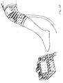
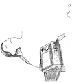
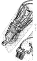
- FIGS. 1A , 1B , 1C and 1D Various systems of this disclosure are shown in FIGS. 1A , 1B , 1C and 1D .
- FIG. 28 shows signal 320, power fluid, and heat connections.
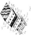
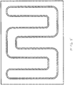
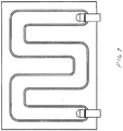
- FIG. 3 is an exploded perspective view of one of the modules 110 showing the various layers including two TPU sheets 400, RF welded 410 to form a channel 420, with angled inlet and outlets 430.
- the channel has a plurality of windows (openings) 440 cut out to expose the interior of the channel at a plurality of locations.
- the sheets, channel with openings and outlet form a water channel shown generally at 450.
- the rest of the module forms a heat exchange stack shown generally at 500.
- the stack includes the bottom plates 520 collectively forming a thermally-conductive plate construction or layer.
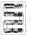
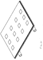
- An alternative plate construction not according to the invention is shown in FIG. 12A where there are plates or plate pieces 540, but no windows.
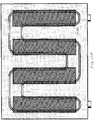
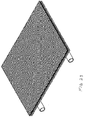
- a further alternative is shown in FIG. 15A where the plate pieces 550 are connected together with a web.
- An advantage of the various plate constructions of the present disclosure are that they provide greater flexibility for the device. The flexibility can be provided about Y axes 600 as shown in FIG. 14 for example. Or with the plate configuration of FIG. 15 about X axes 610 and Y axes 620.
- the TEC Assembly can indude a TEC, the previously-mentioned copper squares, a copper bus line and wires. Thermistors are also shown in the figures.
- a core composite layer 800 has holes 810 cut in it.
- the upper Mylar sheet 830 also has holes 840 cut in it for the TECs.
- the top plate is shown at 850 and the biocompatible layer at 860 .
- the adhesive for attaching the TEC's to the plate pieces (bottom plate) is shown and the thermal paste/epoxy for attaching the TECs to the top plate is shown. And the threads or other mechanical connect are shown.
- the control console can be comprised of the following components:
- the enclosure can be manufactured from laser cut acrylic, cast urethane, injection molded plastic or a similar method. It can be made from a single piece or by joining multiple panels that are either snapped together, screwed together, or by other mechanical or adhesive methods including a combination of the methods.
- the enclosure's main purpose is to house the internal components of the control console as well as mount the input and output ports and connector needed to interface with the umbilical and therefore HEMs. This enclosure can also maintain its rigidity with vents, for heat dissipation.
- the enclosure also can be constructed to maintain safety in the event of a fluid leak near electrical components.
- the input and output components can be panel mounted to interface with a plug, cable, or tube. They can be installed by creating a cut-out in the enclosure of the specified component, such that it can be inserted partially through the hole and mechanically fixed, whether through screws or a snap-in feature.
- the quick disconnect fittings, the power and signal plug, the USB port, the 1/4" jack, and power outlet are all installed in this manner.
- the touch screen is installed in a similar manner but rather than being put through the enclosure, it is mounted such that the profile cut out of the enclosure allows access to the screen without the part extending out.
- the internal components are all mounted by screw mounts or affixed to platforms with various mechanical or even adhesive methods.
- the fan(s) are mounted to the radiator, and the radiator fan system is mounted such that the fans directly come into contact with a vent, and they are screw-mounted into place.
- the pump, AC to DC power supply, necessary DC to DC power supplies (zero to two depending on the design), H-Bridge, microcontroller PCBA, screen driver board are all screw mounted.
- the reservoir is held in place by being mounted on a shelf or platform.
- the AC to DC power supply and battery provide power to all the components in the system. They are installed such that when the device is plugged into a power source the battery is charging, and when the device is unplugged the device operates on the battery. Depending on the design and component power needs, there are additional DC to DC power supplies that are powered by the power supply or battery. This collection of power supplies and battery are referred to as the power supply system.
- the power outlet is then wired with 600V rated cable to the power supply system.
- the power supply system is then distributed to the appropriate components via wiring.
- the components that require power include the fan(s), the pump, the H-Bridge, the microcontroller PCBA, and in some designs, the screen driver board and touch screen may need individual power. There are additional electrical interconnections separate from the power supply system.
- Wiring is necessary between the power and signal plug to the H-Bridge and to the microcontroller PCBA. Additional wiring is necessary from the USB port, 1/4" jack, flow meter, level sensor, H-Bridge, and screen driver board to the microcontroller PCBA. There is also a wiring connection needed between the touch screen and the screen driver board. All this wiring is completed via screw terminals, soldering, crimping, or plugs, depending on the components specification.
- the fluid system within the enclosure is all interconnected with 9,525 mm (3/8") or 6,35 mm (1/4") diameter flexible tubing, such as PVC or polyurethane. They are connected to the individual components using barb or compression fittings. They can be straight or angled, and are screwed into the components.
- the tubing is connected from the reservoir to the pump inlet and from the pump outlet to the outlet quick disconnect fitting, where the umbilical is attached.
- the tubing also goes from the inlet quick disconnect fitting to the radiator and from the radiator back into the reservoir.
- the flow meter is installed with the same barbed fittings.
- a second threaded hole is created in the reservoir so that the level sensor can be installed.
- the umbilical is an extended section of a paired tube, such as PVC or polyurethane, as well as an extended piece of wiring assembly between 1/3 of a meter to four meters.
- There are two tubes for the fluid again either 9,525 mm (3/8") or 6,35 mm (1/4") in diameter and made from a flexible material, that go from quick disconnect fittings of the control console to the HEM.
- the appropriate connector with barbs if necessary, are attached to the ends of these tubes such that it can plug into the quick disconnect fittings and into the HEM.
- the wire assembly is comprised of two cables capable of carrying current to the HEMs and at least two wires that can bring signals from the HEMs temperature probe. Additional wires are included if there are more than one temperature probe being used in the HEM.
- the cables and wires are crimped and soldered appropriately in order to be connected to the terminal of the plugs that goes into the control console on one end and into the HEM on the other end.
- a braided sleeve or other sheathe is then wrapped around the entire cable and tube assembly.
- the touch screen is interfaced by the user and in the simplest case a single temperature below room temperature is set for an indefinite amount of time (it will be possible for the user to set and use or select programmed temperature and time. algorithms).
- the microcontroller receives the temperature signal from the HEM. It responds by transmitting the appropriate signal to the H-Bridge which then, powered by the power supply system, can produce and send the necessary power to the HEM through the umbilical assembly. This allows the HEM to approach the set temperature. This feedback loop is repeated as necessary to maintain the user's selected temperature.
- the heat created by the HEM is being removed via the fluid system. Fluid is continuously flowing in a closed loop.
- the pump is drawing fluid from the reservoir and sending it through the umbilical into the HEM where it collects heat and returns via the umbilical. It then passed through the radiator and returns to the reservoir. When passing through the radiator, the collected heat is dissipated from the air forced through the radiator by the fans. The fans also help to remove excess heat produced from the electrical components in the enclosure.
- HEM Heat Exchange Modules
- TPU thermoplastic polyurethane
- TPU inlets/outlets are also RF welded at the ends of the designed water channels to allow the inlet and outlet of the water to be circulated. These inlets/outlets vary in size and have an inner diameter (ID) of either 6,35 mm (1/4") or 9,525 mm (3/8") depending on the specifications of each HEM.
- ID inner diameter
- the TPU is not thermally conductive, an opening must be created in the water channels to allow for sufficient transfer of heat into the water from the device.
- the TPU sheet that does not have the elbows RF welded to it is cut in the shape of rectangles to form 'windows' in it. This is typically done via die-cutting, but can be done by other methods.
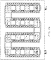
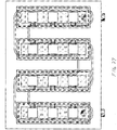
- a number of the figures show the water channels with windows cut out. This figure shows only one of the many possible configurations of the windows cut in the TPU sheet. In reality, the number of windows can range from one large window to as many windows as there are TECs in the device. The higher number of windows, the more flexible the device can be. This will be further explained below.
- a thermally conductive material must be used to seal the water channels to prevent leaking.
- This material is typically a thin metal plate, either copper or aluminum of thickness 0.1778-0.3048 mm (7-12 mils), but can be any semi-flexible thermally conductive substrate.
- the metal plate is cut into pieces that are relatively larger than the window cutouts in the TPU (usually by ⁇ 10mm). The reason a single large piece of metal is not used is to allow for flexibility in the device and to reduce weight. The areas in between the metal plates allow for more flexibility in the device, since the TPU is much more flexible than the metal. Revisiting the windows discussion earlier, the number of metal plates is the same as the number of windows cut out in the water channels.
- a small window can be cut around each TEC (twelve windows total), and twelve metal plates, each a bit bigger than the size of the windows, can be used to seal each window.
- This method would allow for more flexibility since it would have flexibility along two axes instead of just one Because all of these plates lie within the same plane, and for ease of discussion, they will collectively be referred to as the 'bottom plate'.
- This plate may also be referred to as the 'hot plate', since during normal cooling operation this plate will heat up, whereas the 'upper plate' (discussed later) will be cold. (The bottom plate can be broadly referred to as a 'cover.').
- the sealing process involves the use of either a structural adhesive (typically either epoxy or acrylic), or a pressure sensitive transfer tape.
- a structural adhesive typically either epoxy or acrylic
- a pressure sensitive transfer tape examples include: Devcon HP250 (acrylic adhesive), 3M DP8005 (epoxy adhesive), and 3M 9472 (transfer tape).
- a structural adhesive typically either epoxy or acrylic
- a pressure sensitive transfer tape examples include: Devcon HP250 (acrylic adhesive), 3M DP8005 (epoxy adhesive), and 3M 9472 (transfer tape).
- a structural adhesive typically either epoxy or acrylic
- 3M DP8005 epoxy adhesive
- 3M 9472 transfer tape
- the next step is to arrange the modules that produce the cooling effect in the device, the thermoelectric coolers (TECs).
- the TECs operate on electrical power, so they are connected to a power source via bus bars.
- These bus bars are made of copper, thin, flexible, and keep a low profile inside the HEMs. The low profile is essential in maintaining interstitial space within the HEM between the two sides of the TECs.
- the bus bars are highly electrically conductive, which prevents them from heating up. Any heat generated through resistance losses in the wiring would inherently cause the HEM to be less efficient.
- the wiring on each TEC is trimmed down to about 6.35 mm (1/4"). Copper bus bars are cut to the corresponding lengths between TECs, and the TEC wires are soldered to the bus bars.
- FIGS. 10-11 illustrate the TEC assembly.
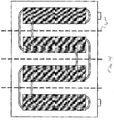
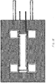
- FIG. 12A is a view similar to FIG. 12 showing the backside of the channel assembly but with the alternative example not according to the invention in which the windows are not cut out, keeping the water channel layer intact.
- FIG. 15A is a view similar to FIG. 15 but of an alternative embodiment connecting the twelve plates with another cover represented here by a hashed pattern.
- This cover can be a meshed material, a material with perforations along the axes of flexibility, such as a perforated foil, or a cover with varying thickness, such as a foil that is thinner along the axes of flexibility, all of which would connect the plates and still provide the axes of rotation for flexibility. It is also possible to do this with four plates or any other number of plates necessary to meet the design requirements.
- This layer can be a thermally conductive metal plate (but can be any semi-flexible thermally conductive substrate) that will be placed on the opposite side of the TECs. This is referred to as the 'upper plate' or 'cold plate'.
- a thermistor is added to this plate to measure the temperature of the surface that is in contact with the skin. To do this, the thermistor is placed in a suitable location (typically the middle of the plate) and the insulated lead wires are taped to the plate using thermally resistant tape.
- a thermally conductive adhesive typically Dow Corning 3-6750
- the adhesive can be cured to set the thermistor in place.
- the interstitial space is defined as the area between the top and bottom metal plates that is not taken us by the TECs or other elements (thermistor, bus lines, etc.).
- a material called a 'core composite' is used, and examples are Koroyd or Amarid Honeycomb. These are structured materials often shaped as a honeycomb with empty cells. See FIG. 12 .
- the core composite can be used instead of, for example, a silicone foam.
- the core composite is cut in the areas where the TECs are present to fill all but those areas between the two metal plates (interstitial space).
- the material is a good thermal insulator because there is air in every core cell, minimizing the amount of heat transfer through material in contact with both plates.
- the core composite also maintains its structure over time, keeping the separation of the top and bottom plates, for thermal insulation.
- the core composite advantageously does not condense or compress over time, which would allow the plates to merge closer to each other.
- the core composite also maintains the structure of the HEM during the mechanical fastening process, preventing the plates from compressing into each other.
- a sheet of Mylar or similar reflective material can be placed on the either side of the core composite for further insulation. These sheets prevent heat from radiating between the two plates by reflecting any emitted radiation back to the plate from which it originates.
- the assembly of the device can use a thermally conductive epoxy to adhere the TECs between the two metal plates, or preferably a thermal paste (typically Arctic MX-4 Compound) that allows for some give between the TECs and the plates on either side of them.
- a thermal paste typically Arctic MX-4 Compound
- a method is needed to hold the device together (basically creating a sandwich that holds the TECs in contact with the metal plates).
- the TECs maintain intimate contact with the metal plates, so that that there is sufficient heat transfer between the materials.
- the mechanical fastening may be sewing, use of rivets, or a similar procedure that will hold the device together structurally. This discussion will use sewing as the primary method, although others are just as viable. Two methods of mechanical fastening may be used, described in the following two subsections.
- the TEC chain that was produced earlier is now used.
- a thin layer or bead of thermally conductive paste is placed onto the "top" surface (the surface to be in contact with the top plate) of each TEC.
- the chain of TECs is then placed on the top plate.
- the first sheet of Mylar is then placed over the top plate around the TECs.
- the core composite is then placed over the Mylar sheet and around the TECs.
- the second Mylar sheet is then placed over the core composite and around the TECs.
- a thin layer or bead of thermally conductive paste is placed onto the 'bottom' surface (surface to be in contact with the bottom plate) of each TEC.
- the bottom plate is then placed on the TECs. Recall that the bottom plate is already sealed to the water channels. At this point, the entire device is mated, and it just needs to be mechanically fastened.
- the main difference between the two methods is how many components the thread (or fastener) will pass through.
- the device is fabricated in a different order, in which the sewing is not the last step, and therefore the thread does not have to pass through the entire device.
- HES what we will now define as the 'heat exchange stack' or HES will be made first. Making the HES follows the same exact procedure as the First Method, the only difference being that the bottom plate is not yet adhered to the water channels. Taking the procedure above for clarity:
- the TEC chain can be as follows. A thin layer or bead of thermally conductive paste is placed onto the 'top' surface (surface to be in contact with the top plate) of each TEC. The chain of TECs is then placed on the top plate.
- the first sheet of Mylar is then placed over the top plate around the TECs.
- the core composite is then placed over the Mylar sheet and around the TECs.
- the second Mylar sheet is then placed over the core composite and around the TECs.
- a thin layer or bead of thermally conductive paste is placed onto the 'bottom' surface (surface to be in contact with the bottom plate) of each TEC.
- the bottom plate is then placed on the TECs.
- the bottom plate in this method can simply be a piece of metal, with the water channels not yet adhered.
- Each metal plate can be sewn individually to the HES similarly to First Method.
- the remaining step is to adhere the water channels to the bottom plate.
- the water channels with windows are made the same as described earlier, and they are adhered to the bottom plate in the same way, the only difference that the bottom plate is already attached the HES on the other side. See FIG. 14 for a cross-sectional view of the Second Method.
- a final step in completing the cooler is adding a thin layer (0.2 to 1 mm) of thermally conductive biocompatible material to the top plate.
- This material acts a buffer between the body tissue and the top plate so that the skin is not in direct contact with metal.
- Biocompatible materials include silicones for medical use, of which a variety are currently available. Alternatively, biocompatible skin adhesives, such as 3M 2476P, are also applicable.
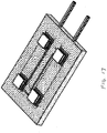
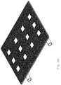
- FIG. 15 shows the completed device, and FIG. 16 shows an exploded view of each layer.
Landscapes
- Health & Medical Sciences (AREA)
- Animal Behavior & Ethology (AREA)
- Public Health (AREA)
- Heart & Thoracic Surgery (AREA)
- Veterinary Medicine (AREA)
- Life Sciences & Earth Sciences (AREA)
- Engineering & Computer Science (AREA)
- General Health & Medical Sciences (AREA)
- Biomedical Technology (AREA)
- Vascular Medicine (AREA)
- Physics & Mathematics (AREA)
- Thermal Sciences (AREA)
- Anesthesiology (AREA)
- Hematology (AREA)
- Thermotherapy And Cooling Therapy Devices (AREA)
Claims (15)
- Wärmeaustauschmodul (500) zur Wärmebehandlung von Körpergewebe eines Subjekts, wobei das Modul folgendes umfasst:eine Fluidkanaleinheit (450), die einen Kanal (420), einen Einlass (430) und einen Auslass (430) umfasst,;einen Wärmeaustauschstapel, der an der Kanaleinheit (450) angebracht ist;wobei der Kanal eine Mehrzahl von Fensteröffnungen (440) aufweist, die so gestaltet sind, dass die das Innere des Kanals exponieren;wobei der Wärmeaustauschstapel thermoelektrische Kühler (670) umfasst;wobei der Wärmeaustauschstapel eine wärmeleitfähige Plattenkonstruktion umfasst, die so gestaltet ist, dass sie Flexibilität für die Kanaleinheit (450) und dadurch für das Wärmeaustauschmodul bereitstellt;wobei die wärmeleitfähige Plattenkonstruktion des Wärmeaustauschstapels wärmeleitfähige Plattenelemente (520) umfasst, die so angebracht sind, dass sie jede der Mehrzahl von Fensteröffnungen (440) abdichten, um eine ausreichende Wärmeübertragung in den Kanal (420) zu ermöglichen;wobei eine erste wärmereflektierende Schicht (650) über den wärmeleitfähigen Plattenelementen (520) und der Kanaleinheit (450) angeordnet ist, wobei die erste wärmereflektierende Schicht (650) Fensterausschnitte aufweist, durch welche die thermoelektrischen Kühler (670) verlaufen, um thermischen Kontakt mit einem der wärmeleitfähigen Plattenelemente (520) herzustellen;wobei eine Kernverbundschicht (800) über der ersten wärmereflektierenden Schicht angeordnet ist, wobei die Kernverbundschicht mit Fenstern (810) gestaltet ist, so dass die Kernverbundschicht jeden der thermoelektrischen Kühler (670) umgibt, um eine Zwischenisolierung bereitzustellen;wobei eine zweite wärmereflektierende Schicht (830) über der Kernverbundschicht angeordnet ist, wobei die wärmereflektierende Schicht Fensterausschnitte (840) für jeden der thermoelektrischen Kühler (670) aufweist;wobei eine wärmeleitfähige obere Platte (850) über der zweiten wärmereflektierenden Schicht angeordnet und so gestaltet ist, dass sie Kontakt mit den thermoelektrischen Kühlern (670) herstellt;wobei eine Kombination aus der ersten wärmereflektierenden Schicht (650) und der zweiten wärmereflektierenden Schicht (830) so gestaltet ist, dass sie es verhindert, dass Wärme zwischen den wärmeleitfähigen Plattenelementen (520) und der wärmeleitfähigen oberen Platte (850) abstrahlt, indem emittierte Strahlung zurück zu der Platte reflektiert wird, von der sie stammt; undwobei eine wärmeleitfähige biokompatible Schicht (860) über der oberen Platte angeordnet ist, wobei die biokompatible Schicht so gestaltet ist, dass sie als Puffer zwischen der wärmeleitfähigen oberen Platte und Körpergewebe fungiert, auf welches das Wärmeaustauschmodul angewendet wird.
- Wärmeaustauschmodul (500) nach Anspruch 1, wobei die wärmeleitfähige Plattenkonstruktion für Flexibilität entlang mindestens einer Achse gestaltet ist.
- Wärmeaustauschmodul (500) nach Anspruch 1, wobei die wärmeleitfähigen Plattenelemente (520) dünne Metallplatten umfassen.
- Wärmeaustauschmodul (500) nach Anspruch 1, wobei die wärmeleitfähigen Plattenelemente (520) so angebracht sind, dass sie die Mehrzahl von Fensteröffnungen (440) unter Verwendung eines Strukturklebstoffs oder eines Haftklebebands abdichten.
- Wärmeaustauschmodul (500) nach Anspruch 1, wobei die wärmeleitfähige Plattenkonstruktion eine flexible Schicht umfasst, welche die wärmeleitfähigen Plattenelemente verbindet.
- Wärmeaustauschmodul (500) nach Anspruch 5, wobei die flexible Schicht ein Gitter, perforiertes Material oder ein dünneres Material ist, das so gestaltet ist, dass es die Flexibilität zwischen den wärmeleitfähigen Plattenelementen erhöht.
- Wärmeaustauschmodul (500) nach Anspruch 1, das ferner einen a Thermistor umfasst, der mit der wärmeleitfähigen oberen Platte (850) gekoppelt ist.
- Wärmeaustauschmodul (500) nach Anspruch 1, wobei die Kernverbundschicht vorgeformte Durchgangsöffnungen umfasst, in denen die thermoelektrischen Kühler positioniert sind.
- Wärmeaustauschmodul (500) nach Anspruch 1, wobei das Modul für eine Verbindung mit einer Konsole (110) über eine Verbindungsleitung (120) gestaltet ist, und wobei der Fluidfluss durch die Kanaleinheit und den thermoelektrischen Kühlern zugeführter Strom durch die Konsole geregelt werden.
- Wärmeaustauschmodul (500) nach Anspruch 1, wobei jeder der thermoelektrischen Kühler (670) durch ein wärmeleitfähiges Epoxidharz oder eine thermische Paste an eines der wärmeleitfähigen Plattenelemente (520) und an die wärmeleitfähige obere Platte (850) geklebt ist.
- Wärmeaustauschmodul (500) nach Anspruch 1, wobei die erste wärmereflektierende Schicht und die zweite wärmereflektierende Schicht ein Mylar-Lagenmaterial umfassen.
- Wärmeaustauschmodul (500) nach Anspruch 1, wobei die Kanaleinheit (45) zwei Lagen aus thermoplastischem Polyurethan (TPU) umfasst, die durch Hochfrequenzschweißen in den Kanälen für einen Wasserfluss dort hindurch angebracht sind.
- Wärmeaustauschmodul (500) nach Anspruch 1, das ferne eine mechanische Sicherung umfasst, mit einer Mehrzahl beabstandeter mechanischer Befestigungsmittel oder einem Nähfaden, der entweder durch die Kanaleinheit zu dem Wärmeaustauschstapel verläuft, oder der durch den Wärmeaustauschstapel verläuft und nicht durch die Kanaleinheit verläuft.
- Wärmeaustauschmodul (500) nach Anspruch 1, wobei die thermoelektrischen Kühler (670) über Stromschienen mit einer Stromversorgung verbunden sind.
- Wärmeaustauschmodul (500) nach Anspruch 1, wobei die Kernverbundschicht eine Wabenstruktur oder eine leere Zellenstruktur aufweist.
Applications Claiming Priority (1)
| Application Number | Priority Date | Filing Date | Title |
|---|---|---|---|
| PCT/US2016/024592 WO2017171719A1 (en) | 2016-03-28 | 2016-03-28 | Heat exchange module and system for medical applications |
Publications (3)
| Publication Number | Publication Date |
|---|---|
| EP3436144A1 EP3436144A1 (de) | 2019-02-06 |
| EP3436144A4 EP3436144A4 (de) | 2019-10-23 |
| EP3436144B1 true EP3436144B1 (de) | 2021-07-07 |
Family
ID=59966300
Family Applications (1)
| Application Number | Title | Priority Date | Filing Date |
|---|---|---|---|
| EP16897277.6A Active EP3436144B1 (de) | 2016-03-28 | 2016-03-28 | Wärmeaustauschmodul und -system für medizinische anwendungen |
Country Status (9)
| Country | Link |
|---|---|
| US (1) | US11419754B2 (de) |
| EP (1) | EP3436144B1 (de) |
| JP (1) | JP2019509844A (de) |
| KR (1) | KR20180126493A (de) |
| CN (1) | CN109475747A (de) |
| AU (1) | AU2016401161A1 (de) |
| CA (1) | CA3019306A1 (de) |
| IL (1) | IL261866A (de) |
| WO (1) | WO2017171719A1 (de) |
Families Citing this family (15)
| Publication number | Priority date | Publication date | Assignee | Title |
|---|---|---|---|---|
| US10201935B2 (en) * | 2007-03-19 | 2019-02-12 | Augustine Temperature Management LLC | Electric heating pad |
| EP3278047B1 (de) | 2015-03-28 | 2022-05-04 | The Regents of The University of California | Thermoelektrischer temperaturgesteuerter kühler für biomedizinische anwendungen |
| KR20190011714A (ko) | 2016-03-28 | 2019-02-07 | 더 리전트 오브 더 유니버시티 오브 캘리포니아 | 열교환 모듈, 시스템 및 방법 |
| EP3436144B1 (de) | 2016-03-28 | 2021-07-07 | The Regents of the University of California | Wärmeaustauschmodul und -system für medizinische anwendungen |
| US11025034B2 (en) * | 2016-08-31 | 2021-06-01 | Nlight, Inc. | Laser cooling system |
| CN110225733B (zh) | 2016-09-28 | 2022-08-23 | 加利福尼亚大学董事会 | 换热模块、系统和方法 |
| WO2019178003A1 (en) | 2018-03-12 | 2019-09-19 | Nlight, Inc. | Fiber laser having variably wound optical fiber |
| US11638675B2 (en) * | 2018-11-07 | 2023-05-02 | Zenith Technical Innovations, Llc | System and method for heat or cold therapy and compression therapy |
| US10765580B1 (en) | 2019-03-27 | 2020-09-08 | Augustine Biomedical And Design, Llc | Patient securement system for the surgical trendelenburg position |
| EP4031079B1 (de) * | 2019-09-16 | 2024-10-09 | Coral Star Medical Ltd. | Orthopädische stütze |
| WO2021118609A1 (en) | 2019-12-09 | 2021-06-17 | Hypothermia Devices, Inc. | Optimized water channels and flexible coolers for use in heat exchange module(s), systems, and methods thereof |
| EP4252723A1 (de) * | 2020-03-27 | 2023-10-04 | Quickcool AB | Entfernbares flüssigkeitswärmeaustauschelement zur verwendung in einer vorrichtung zur temperaturregelungsbehandlung |
| GB2623669A (en) * | 2021-07-22 | 2024-04-24 | Kota Kiran | Flexible thermoelectric device |
| JP2025521570A (ja) | 2022-06-23 | 2025-07-10 | オーガスタイン バイオメディカル アンド デザイン,リミティド ライアビリティ カンパニー | 外科的トレンデレンブルグ体位のための患者固定システム |
| CN116887656B (zh) * | 2023-07-28 | 2025-01-28 | 东莞理工学院 | 一种基于负泊松比结构的柔性热电器件及应用 |
Family Cites Families (106)
| Publication number | Priority date | Publication date | Assignee | Title |
|---|---|---|---|---|
| US2991627A (en) | 1959-07-01 | 1961-07-11 | Gen Electric | Thermoelectric blanket |
| US3196524A (en) | 1961-04-18 | 1965-07-27 | Carrier Corp | Thermoelectric cooling devices and method of making the same |
| US3867939A (en) * | 1972-05-18 | 1975-02-25 | Moore Perk Corp | Disposable, sterile temperature control applicator pad for medical application |
| US4470263A (en) | 1980-10-14 | 1984-09-11 | Kurt Lehovec | Peltier-cooled garment |
| SU1179987A1 (ru) | 1982-07-23 | 1985-09-23 | Всесоюзный Научно-Исследовательский Проектно-Конструкторский И Технологический Институт Источников Тока | Устройство дл локальной гипотермии |
| US4846176A (en) * | 1987-02-24 | 1989-07-11 | Golden Theodore A | Thermal bandage |
| US4962761A (en) * | 1987-02-24 | 1990-10-16 | Golden Theodore A | Thermal bandage |
| US4860748A (en) | 1988-02-23 | 1989-08-29 | Thermapeutics, Inc. | Thermal pattern generator for pain relief |
| US5174285A (en) | 1990-01-08 | 1992-12-29 | Lake Shore Medical Development Partners Ltd. | Localized heat transfer device |
| US5097829A (en) * | 1990-03-19 | 1992-03-24 | Tony Quisenberry | Temperature controlled cooling system |
| JPH0477915A (ja) | 1990-07-20 | 1992-03-12 | Toshiba Corp | 磁気ディスク制御装置 |
| DE4238291A1 (de) * | 1992-11-13 | 1994-05-19 | Diehl Gmbh & Co | Vorrichtung zur kleinflächigen Vereisung von Oberflächen |
| US5871526A (en) | 1993-10-13 | 1999-02-16 | Gibbs; Roselle | Portable temperature control system |
| US5584183A (en) | 1994-02-18 | 1996-12-17 | Solid State Cooling Systems | Thermoelectric heat exchanger |
| US5603728A (en) | 1994-06-20 | 1997-02-18 | Pachys; Freddy | Scalp cooling/heating apparatus |
| US5895418A (en) * | 1994-09-30 | 1999-04-20 | Saringer Research Inc. | Device for producing cold therapy |
| US5653741A (en) * | 1995-08-22 | 1997-08-05 | Grant; Edward F. | Heating and cooling pad |
| US5887435A (en) | 1995-12-08 | 1999-03-30 | Litton Systems, Inc. | Environmentally protected module |
| US5800490A (en) * | 1996-11-07 | 1998-09-01 | Patz; Herbert Samuel | Lightweight portable cooling or heating device with multiple applications |
| US5899077A (en) * | 1997-12-02 | 1999-05-04 | Solid State Cooling Systems, Inc. | Thermoelectric cooling/heating system for high purity or corrosive liquids |
| CA2356993C (en) | 1999-01-04 | 2009-06-23 | Medivance, Inc. | Improved cooling/heating pad and system |
| US6019783A (en) * | 1999-03-02 | 2000-02-01 | Alsius Corporation | Cooling system for therapeutic catheter |
| US6205790B1 (en) | 1999-05-28 | 2001-03-27 | Lucent Technologies Inc. | Efficient thermoelectric controller |
| US6402775B1 (en) * | 1999-12-14 | 2002-06-11 | Augustine Medical, Inc. | High-efficiency cooling pads, mattresses, and sleeves |
| US6840955B2 (en) | 2000-01-27 | 2005-01-11 | Robert J. Ein | Therapeutic apparatus |
| AU6687401A (en) | 2000-06-14 | 2001-12-24 | Inc American Healthcare Produc | Heating pad systems, such as for patient warming applications |
| DE10065592A1 (de) | 2000-12-28 | 2002-07-04 | Werner Sinnig | Wärme-Kälte Verfahren und Geräte zur Schmerzbehandlung insbesondere von akutem Spannungskopfschmerz und Migräne |
| US6511502B2 (en) | 2001-02-27 | 2003-01-28 | Robert David Fletcher | Apparatus for and method of cooling a brain |
| CA2382928A1 (en) | 2001-04-23 | 2002-10-23 | Stephen Cheung | Thermal control suit |
| US6461379B1 (en) | 2001-04-30 | 2002-10-08 | Medivance, Incorporated | Localized bodily cooling/heating apparatus and method |
| US6739138B2 (en) | 2001-11-26 | 2004-05-25 | Innovations Inc. | Thermoelectric modules and a heating and cooling apparatus incorporating same |
| JP2003323219A (ja) | 2002-01-22 | 2003-11-14 | Thermo Solution:Kk | 温度調節器 |
| US7052509B2 (en) | 2002-04-29 | 2006-05-30 | Medcool, Inc. | Method and device for rapidly inducing and then maintaining hypothermia |
| CA2497181C (en) * | 2002-09-12 | 2013-08-13 | Radiant Medical, Inc. | System and method for determining and controlling core body temperature |
| US6915641B2 (en) * | 2003-01-14 | 2005-07-12 | Mark R. Harvie | Personal cooling and heating system |
| CA2432860A1 (en) | 2003-06-16 | 2004-12-16 | Dupont Canada Inc. | Distributed electronic personal heat management system |
| EP1646351B1 (de) | 2003-07-18 | 2011-03-30 | Thermotek, Inc. | Thermisches system für eine decke |
| US7077858B2 (en) * | 2003-09-22 | 2006-07-18 | Coolhead Technologies, Inc. | Flexible heat exchangers for medical cooling and warming applications |
| US7022093B2 (en) * | 2003-10-06 | 2006-04-04 | Thermodesigns, Inc. | Self-contained heating and cooling orthopaedic brace |
| US8062797B2 (en) * | 2004-05-07 | 2011-11-22 | Ardica Technologies, Inc. | Articles of clothing and personal gear with on-demand power supply for electrical devices |
| US7959657B1 (en) * | 2004-07-07 | 2011-06-14 | Harsy Douglas R | Portable thermal therapeutic apparatus and method |
| GB2422109B (en) * | 2005-01-13 | 2007-02-21 | Richard Mills | Apparatus for providing a heating and cooling effect |
| JP2006230761A (ja) | 2005-02-25 | 2006-09-07 | Nippon System Group:Kk | 医療用ペルチェ式部分冷却装置 |
| US7494945B2 (en) | 2005-05-26 | 2009-02-24 | Energy Integration Technologies, Inc. | Thin film energy fabric |
| US20060293732A1 (en) | 2005-06-27 | 2006-12-28 | Collins Kenneth A | Thermoelectric cooler (TEC) heat exchanger for intravascular heat exchange catheter |
| US7181927B2 (en) | 2005-07-01 | 2007-02-27 | Alsius Corporation | Primary heat exchanger for patient temperature control |
| US20080046047A1 (en) | 2006-08-21 | 2008-02-21 | Daniel Jacobs | Hot and cold therapy device |
| US9132031B2 (en) | 2006-09-26 | 2015-09-15 | Zeltiq Aesthetics, Inc. | Cooling device having a plurality of controllable cooling elements to provide a predetermined cooling profile |
| US8192474B2 (en) * | 2006-09-26 | 2012-06-05 | Zeltiq Aesthetics, Inc. | Tissue treatment methods |
| US20080077201A1 (en) | 2006-09-26 | 2008-03-27 | Juniper Medical, Inc. | Cooling devices with flexible sensors |
| EP2606771B1 (de) | 2006-10-13 | 2015-01-07 | Gentherm Incorporated | Klimatisiertes Bett |
| US8529613B2 (en) | 2006-10-18 | 2013-09-10 | Medcool, Inc. | Adjustable thermal cap |
| US20080097562A1 (en) * | 2006-10-19 | 2008-04-24 | Dyamed Biotech Pte Ltd | System For Chemohyperthermia Treatment |
| DE202006020386U1 (de) | 2006-12-08 | 2008-07-17 | Kipper, Manuela | Einrichtung zum Betrieb einer kombinierten Heiz- und Kühleinrichtung |
| JP2010515481A (ja) | 2007-01-09 | 2010-05-13 | テイアサイエンス・インコーポレーテツド | マイボーム腺の治療 |
| US8283602B2 (en) * | 2007-03-19 | 2012-10-09 | Augustine Temperature Management LLC | Heating blanket |
| US20080249524A1 (en) * | 2007-04-03 | 2008-10-09 | Tyco Healthcare Group Lp | System and method for providing even heat distribution and cooling return pads |
| US20100132930A1 (en) | 2007-05-02 | 2010-06-03 | Creare, Inc. | Flexible Heat/Mass Exchanger |
| US20080287839A1 (en) * | 2007-05-18 | 2008-11-20 | Juniper Medical, Inc. | Method of enhanced removal of heat from subcutaneous lipid-rich cells and treatment apparatus having an actuator |
| US7765811B2 (en) | 2007-06-29 | 2010-08-03 | Laird Technologies, Inc. | Flexible assemblies with integrated thermoelectric modules suitable for use in extracting power from or dissipating heat from fluid conduits |
| EP2214824A4 (de) | 2007-11-28 | 2015-08-19 | Smart Tube Inc | Vorrichtungen, systeme und verfahren zur entnahme, stimulation, stabilisierung und analyse einer biologischen probe |
| WO2009086058A1 (en) * | 2007-12-19 | 2009-07-09 | Mcneil-Ppc, Inc. | Thermal treatment device |
| US20090264969A1 (en) * | 2008-04-20 | 2009-10-22 | Adroit Development, Inc. | Multi-mode cooling garment |
| WO2010005744A2 (en) * | 2008-06-16 | 2010-01-14 | Robert Besner | Far infrared heat emitting therapeutic device |
| KR100915320B1 (ko) * | 2008-09-29 | 2009-09-03 | (주)메디룬 | 생리통완화를 위한 휴대용 조합자극기 |
| US20100198322A1 (en) | 2009-02-05 | 2010-08-05 | Disney Enterprises, Inc. | Personal temperature regulator |
| US8361133B2 (en) * | 2009-04-14 | 2013-01-29 | Vivonics, Inc. | Patient warming appliqué |
| DE102009003144A1 (de) | 2009-05-15 | 2010-11-18 | Robert Bosch Gmbh | Wärmeübertrager und Verfahren zur Umwandlung von thermischer Energie eines Fluids in elektrische Energie |
| JP2011000884A (ja) | 2009-06-17 | 2011-01-06 | Laird Technologies Inc | 適合型多層熱伝導性中間構体およびそれを具備するメモリモジュール |
| US20110030754A1 (en) * | 2009-08-06 | 2011-02-10 | Laird Technologies, Inc. | Thermoelectric modules and related methods |
| US20110071603A1 (en) * | 2009-09-24 | 2011-03-24 | Joshua John Edward Moore | Cyclic Heat Therapy Device |
| EP2528560A1 (de) * | 2010-01-25 | 2012-12-05 | Zeltiq Aesthetics, Inc. | Applikatoren zur heimanwendung zur nichtinvasiven entfernung von hitze aus subkutanen fettreichen zellen mithilfe von phasenwechsel-kühlungsmitteln sowie entsprechende vorrichtungen, systeme und verfahren |
| WO2011156643A1 (en) | 2010-06-11 | 2011-12-15 | Mandel William R | Apparatus for therapeutic cooling and warming of a body portion of a human or mammal |
| WO2012103242A1 (en) * | 2011-01-25 | 2012-08-02 | Zeltiq Aesthetics, Inc. | Devices, application systems and methods with localized heat flux zones for removing heat from subcutaneous lipid-rich cells |
| WO2012138980A2 (en) | 2011-04-06 | 2012-10-11 | Coolsystems, Inc. | System for providing treatment to a mammal and method |
| BR112014000666A2 (pt) * | 2011-07-20 | 2019-06-04 | Scr Inc | almofada de aquecimento e/ou resfriamento e sistema de fornecimento de resfiamento a uma ou mais partes do corpo de um indivíduo e respectivo método para fornecer terapia de quente e frio |
| JP5354819B2 (ja) * | 2011-11-16 | 2013-11-27 | 株式会社ライト光機製作所 | 液体保持具および冷却・加熱装置 |
| US9510972B2 (en) | 2012-01-04 | 2016-12-06 | Sight Sciences, Inc. | Dry eye treatment systems |
| US8397518B1 (en) | 2012-02-20 | 2013-03-19 | Dhama Innovations PVT. Ltd. | Apparel with integral heating and cooling device |
| GB2500633A (en) | 2012-03-27 | 2013-10-02 | Louise Mohn | Moulding method |
| GB201211337D0 (en) | 2012-06-26 | 2012-08-08 | Philp Paul M | Heat therapy garment |
| US9078478B2 (en) * | 2012-07-09 | 2015-07-14 | Medlab, LLC | Therapeutic sleeve device |
| US10376412B2 (en) | 2012-07-16 | 2019-08-13 | University of Pittsburgh—of the Commonwealth System of Higher Education | Actively and selectively cooled cushioning surface |
| US9849025B2 (en) | 2012-09-07 | 2017-12-26 | Yale University | Brain cooling system |
| ITMO20120246A1 (it) * | 2012-10-10 | 2014-04-11 | Enrico Giuliani | Collare terapeutico |
| US9278023B2 (en) * | 2012-12-14 | 2016-03-08 | Zoll Circulation, Inc. | System and method for management of body temperature |
| US9956113B2 (en) * | 2013-03-12 | 2018-05-01 | The Board Of Trustees Of The Leland Stanford Junior University | Method and system for regulating core body temperature |
| CN103142217A (zh) | 2013-03-13 | 2013-06-12 | 江西师范大学 | 电子体温监控器 |
| WO2014145293A2 (en) | 2013-03-15 | 2014-09-18 | Vecarius, Inc. | Thermoelectric device |
| JP6078412B2 (ja) | 2013-04-17 | 2017-02-08 | 日立化成株式会社 | 熱電変換式発電装置 |
| US20140326287A1 (en) * | 2013-05-02 | 2014-11-06 | Perpetua Power Source Technologies, Inc. | Wearable thermoelectric generator assembly and method of manufacturing same |
| CN203341808U (zh) | 2013-05-14 | 2013-12-18 | 上海市闸北区彭浦镇社区卫生服务中心 | 一种多功能冷疗仪 |
| US20140352325A1 (en) * | 2013-06-03 | 2014-12-04 | Wendell Brown | Electronic coldpack and method of use |
| AU2014326780B2 (en) | 2013-09-30 | 2019-05-02 | The Regents Of The University Of California | Portable thermoelectric cooling device for therapeutic craniocervical hypothermia |
| KR101582814B1 (ko) | 2014-01-10 | 2016-01-07 | 주식회사모토디자인 | 온열장치 및 이동통신기기 |
| JP6652493B2 (ja) * | 2014-02-14 | 2020-02-26 | ジェンサーム インコーポレイテッドGentherm Incorporated | 伝導性および対流性の温度調節シート |
| US20150366703A1 (en) * | 2014-06-18 | 2015-12-24 | Xing Du | Alternating hot and cold therapy apparatus |
| WO2016011408A1 (en) * | 2014-07-17 | 2016-01-21 | The Regents Of The University Of California | Sewing as a method for joint reinforcement between plastics and other materials |
| US10393414B2 (en) | 2014-12-19 | 2019-08-27 | Palo Alto Research Center Incorporated | Flexible thermal regulation device |
| DE102015202968A1 (de) | 2015-02-19 | 2016-08-25 | Mahle International Gmbh | Wärmeleitende und elektrisch isolierende Verbindung für ein thermoelektrisches Modul |
| EP3278047B1 (de) * | 2015-03-28 | 2022-05-04 | The Regents of The University of California | Thermoelektrischer temperaturgesteuerter kühler für biomedizinische anwendungen |
| US10652993B2 (en) | 2015-07-20 | 2020-05-12 | Ii-Vi Delaware, Inc. | Thermoelectric device cooling system |
| EP3436144B1 (de) | 2016-03-28 | 2021-07-07 | The Regents of the University of California | Wärmeaustauschmodul und -system für medizinische anwendungen |
| KR20190011714A (ko) | 2016-03-28 | 2019-02-07 | 더 리전트 오브 더 유니버시티 오브 캘리포니아 | 열교환 모듈, 시스템 및 방법 |
| WO2018064220A1 (en) | 2016-09-28 | 2018-04-05 | Hypothermia Devices, Inc. | Heat exchange module, system and method |
| CN110225733B (zh) * | 2016-09-28 | 2022-08-23 | 加利福尼亚大学董事会 | 换热模块、系统和方法 |
-
2016
- 2016-03-28 EP EP16897277.6A patent/EP3436144B1/de active Active
- 2016-03-28 AU AU2016401161A patent/AU2016401161A1/en not_active Abandoned
- 2016-03-28 WO PCT/US2016/024592 patent/WO2017171719A1/en not_active Ceased
- 2016-03-28 KR KR1020187028057A patent/KR20180126493A/ko not_active Ceased
- 2016-03-28 CA CA3019306A patent/CA3019306A1/en not_active Abandoned
- 2016-03-28 JP JP2018550772A patent/JP2019509844A/ja active Pending
- 2016-03-28 CN CN201680084088.7A patent/CN109475747A/zh active Pending
-
2018
- 2018-09-20 US US16/136,724 patent/US11419754B2/en active Active
- 2018-09-20 IL IL261866A patent/IL261866A/en unknown
Non-Patent Citations (1)
| Title |
|---|
| None * |
Also Published As
| Publication number | Publication date |
|---|---|
| CA3019306A1 (en) | 2017-10-05 |
| CN109475747A (zh) | 2019-03-15 |
| US20190099287A1 (en) | 2019-04-04 |
| US11419754B2 (en) | 2022-08-23 |
| IL261866A (en) | 2018-10-31 |
| EP3436144A1 (de) | 2019-02-06 |
| WO2017171719A1 (en) | 2017-10-05 |
| AU2016401161A1 (en) | 2018-10-18 |
| JP2019509844A (ja) | 2019-04-11 |
| KR20180126493A (ko) | 2018-11-27 |
| EP3436144A4 (de) | 2019-10-23 |
Similar Documents
| Publication | Publication Date | Title |
|---|---|---|
| US11419754B2 (en) | Heat exchange module and system for medical applications | |
| US11903872B2 (en) | Heat exchange module, system and method | |
| US4962761A (en) | Thermal bandage | |
| US5653741A (en) | Heating and cooling pad | |
| US10406024B2 (en) | Wearable temperature therapy system and method | |
| US6799063B2 (en) | Temperature control pads with integral electrodes | |
| US20230053398A1 (en) | Heat exchange module, system and method | |
| US20190350752A1 (en) | Wearable temperature therapy system and method | |
| US4846176A (en) | Thermal bandage | |
| US7077858B2 (en) | Flexible heat exchangers for medical cooling and warming applications | |
| CN114796860B (zh) | 皮肤保养组件和接触式美容仪 | |
| CN110013378B (zh) | 具有多个可控冷却元件以提供预定冷却分布曲线的冷却装置 | |
| ES2764776T3 (es) | Dispositivos de enfriamiento con sensores flexibles | |
| JP2019509844A5 (de) | ||
| GB2540863A (en) | Therapeutic apparatus | |
| WO2018064220A1 (en) | Heat exchange module, system and method | |
| JP2018513723A (ja) | 生体応用のための熱電温度制御冷却器 | |
| JP2016137115A (ja) | ヘッドキャップ | |
| US20180071138A1 (en) | Thermo electric cooling systems for hypothermia therapy treatment | |
| CN114191718B (zh) | 电场发生电极贴及肿瘤电场治疗装置 | |
| CN223380688U (zh) | 一种可实现保暖和冷敷的救治设备 | |
| WO2024064343A1 (en) | Devices and methods for safely and effectively raising or maintaining core body temperature | |
| HK40013002A (en) | Cooling device having a plurality of controllable cooling elements to provide a predetermined cooling profile | |
| HK40013002B (en) | Cooling device having a plurality of controllable cooling elements to provide a predetermined cooling profile |
Legal Events
| Date | Code | Title | Description |
|---|---|---|---|
| STAA | Information on the status of an ep patent application or granted ep patent |
Free format text: STATUS: THE INTERNATIONAL PUBLICATION HAS BEEN MADE |
|
| PUAI | Public reference made under article 153(3) epc to a published international application that has entered the european phase |
Free format text: ORIGINAL CODE: 0009012 |
|
| STAA | Information on the status of an ep patent application or granted ep patent |
Free format text: STATUS: REQUEST FOR EXAMINATION WAS MADE |
|
| 17P | Request for examination filed |
Effective date: 20181012 |
|
| AK | Designated contracting states |
Kind code of ref document: A1 Designated state(s): AL AT BE BG CH CY CZ DE DK EE ES FI FR GB GR HR HU IE IS IT LI LT LU LV MC MK MT NL NO PL PT RO RS SE SI SK SM TR |
|
| AX | Request for extension of the european patent |
Extension state: BA ME |
|
| RIN1 | Information on inventor provided before grant (corrected) |
Inventor name: PADULA, ANDREW Inventor name: ESTRADA, DANIEL M. Inventor name: VERGARA, JULIO L. |
|
| DAV | Request for validation of the european patent (deleted) | ||
| DAX | Request for extension of the european patent (deleted) | ||
| A4 | Supplementary search report drawn up and despatched |
Effective date: 20190925 |
|
| RIC1 | Information provided on ipc code assigned before grant |
Ipc: A61F 7/00 20060101ALI20190919BHEP Ipc: A61N 1/40 20060101AFI20190919BHEP Ipc: A61F 7/02 20060101ALI20190919BHEP Ipc: A61F 7/12 20060101ALI20190919BHEP |
|
| GRAP | Despatch of communication of intention to grant a patent |
Free format text: ORIGINAL CODE: EPIDOSNIGR1 |
|
| STAA | Information on the status of an ep patent application or granted ep patent |
Free format text: STATUS: GRANT OF PATENT IS INTENDED |
|
| INTG | Intention to grant announced |
Effective date: 20201116 |
|
| GRAS | Grant fee paid |
Free format text: ORIGINAL CODE: EPIDOSNIGR3 |
|
| GRAJ | Information related to disapproval of communication of intention to grant by the applicant or resumption of examination proceedings by the epo deleted |
Free format text: ORIGINAL CODE: EPIDOSDIGR1 |
|
| GRAL | Information related to payment of fee for publishing/printing deleted |
Free format text: ORIGINAL CODE: EPIDOSDIGR3 |
|
| STAA | Information on the status of an ep patent application or granted ep patent |
Free format text: STATUS: REQUEST FOR EXAMINATION WAS MADE |
|
| GRAP | Despatch of communication of intention to grant a patent |
Free format text: ORIGINAL CODE: EPIDOSNIGR1 |
|
| STAA | Information on the status of an ep patent application or granted ep patent |
Free format text: STATUS: GRANT OF PATENT IS INTENDED |
|
| INTC | Intention to grant announced (deleted) | ||
| INTG | Intention to grant announced |
Effective date: 20210420 |
|
| GRAA | (expected) grant |
Free format text: ORIGINAL CODE: 0009210 |
|
| STAA | Information on the status of an ep patent application or granted ep patent |
Free format text: STATUS: THE PATENT HAS BEEN GRANTED |
|
| AK | Designated contracting states |
Kind code of ref document: B1 Designated state(s): AL AT BE BG CH CY CZ DE DK EE ES FI FR GB GR HR HU IE IS IT LI LT LU LV MC MK MT NL NO PL PT RO RS SE SI SK SM TR |
|
| REG | Reference to a national code |
Ref country code: GB Ref legal event code: FG4D |
|
| REG | Reference to a national code |
Ref country code: AT Ref legal event code: REF Ref document number: 1407967 Country of ref document: AT Kind code of ref document: T Effective date: 20210715 |
|
| REG | Reference to a national code |
Ref country code: DE Ref legal event code: R096 Ref document number: 602016060466 Country of ref document: DE |
|
| REG | Reference to a national code |
Ref country code: NL Ref legal event code: FP |
|
| REG | Reference to a national code |
Ref country code: IE Ref legal event code: FG4D |
|
| REG | Reference to a national code |
Ref country code: LT Ref legal event code: MG9D |
|
| REG | Reference to a national code |
Ref country code: AT Ref legal event code: MK05 Ref document number: 1407967 Country of ref document: AT Kind code of ref document: T Effective date: 20210707 |
|
| PG25 | Lapsed in a contracting state [announced via postgrant information from national office to epo] |
Ref country code: LT Free format text: LAPSE BECAUSE OF FAILURE TO SUBMIT A TRANSLATION OF THE DESCRIPTION OR TO PAY THE FEE WITHIN THE PRESCRIBED TIME-LIMIT Effective date: 20210707 Ref country code: AT Free format text: LAPSE BECAUSE OF FAILURE TO SUBMIT A TRANSLATION OF THE DESCRIPTION OR TO PAY THE FEE WITHIN THE PRESCRIBED TIME-LIMIT Effective date: 20210707 Ref country code: BG Free format text: LAPSE BECAUSE OF FAILURE TO SUBMIT A TRANSLATION OF THE DESCRIPTION OR TO PAY THE FEE WITHIN THE PRESCRIBED TIME-LIMIT Effective date: 20211007 Ref country code: NO Free format text: LAPSE BECAUSE OF FAILURE TO SUBMIT A TRANSLATION OF THE DESCRIPTION OR TO PAY THE FEE WITHIN THE PRESCRIBED TIME-LIMIT Effective date: 20211007 Ref country code: PT Free format text: LAPSE BECAUSE OF FAILURE TO SUBMIT A TRANSLATION OF THE DESCRIPTION OR TO PAY THE FEE WITHIN THE PRESCRIBED TIME-LIMIT Effective date: 20211108 Ref country code: HR Free format text: LAPSE BECAUSE OF FAILURE TO SUBMIT A TRANSLATION OF THE DESCRIPTION OR TO PAY THE FEE WITHIN THE PRESCRIBED TIME-LIMIT Effective date: 20210707 Ref country code: FI Free format text: LAPSE BECAUSE OF FAILURE TO SUBMIT A TRANSLATION OF THE DESCRIPTION OR TO PAY THE FEE WITHIN THE PRESCRIBED TIME-LIMIT Effective date: 20210707 Ref country code: ES Free format text: LAPSE BECAUSE OF FAILURE TO SUBMIT A TRANSLATION OF THE DESCRIPTION OR TO PAY THE FEE WITHIN THE PRESCRIBED TIME-LIMIT Effective date: 20210707 Ref country code: SE Free format text: LAPSE BECAUSE OF FAILURE TO SUBMIT A TRANSLATION OF THE DESCRIPTION OR TO PAY THE FEE WITHIN THE PRESCRIBED TIME-LIMIT Effective date: 20210707 Ref country code: RS Free format text: LAPSE BECAUSE OF FAILURE TO SUBMIT A TRANSLATION OF THE DESCRIPTION OR TO PAY THE FEE WITHIN THE PRESCRIBED TIME-LIMIT Effective date: 20210707 |
|
| PG25 | Lapsed in a contracting state [announced via postgrant information from national office to epo] |
Ref country code: PL Free format text: LAPSE BECAUSE OF FAILURE TO SUBMIT A TRANSLATION OF THE DESCRIPTION OR TO PAY THE FEE WITHIN THE PRESCRIBED TIME-LIMIT Effective date: 20210707 Ref country code: LV Free format text: LAPSE BECAUSE OF FAILURE TO SUBMIT A TRANSLATION OF THE DESCRIPTION OR TO PAY THE FEE WITHIN THE PRESCRIBED TIME-LIMIT Effective date: 20210707 Ref country code: GR Free format text: LAPSE BECAUSE OF FAILURE TO SUBMIT A TRANSLATION OF THE DESCRIPTION OR TO PAY THE FEE WITHIN THE PRESCRIBED TIME-LIMIT Effective date: 20211008 |
|
| REG | Reference to a national code |
Ref country code: DE Ref legal event code: R097 Ref document number: 602016060466 Country of ref document: DE |
|
| PG25 | Lapsed in a contracting state [announced via postgrant information from national office to epo] |
Ref country code: DK Free format text: LAPSE BECAUSE OF FAILURE TO SUBMIT A TRANSLATION OF THE DESCRIPTION OR TO PAY THE FEE WITHIN THE PRESCRIBED TIME-LIMIT Effective date: 20210707 |
|
| PLBE | No opposition filed within time limit |
Free format text: ORIGINAL CODE: 0009261 |
|
| STAA | Information on the status of an ep patent application or granted ep patent |
Free format text: STATUS: NO OPPOSITION FILED WITHIN TIME LIMIT |
|
| PG25 | Lapsed in a contracting state [announced via postgrant information from national office to epo] |
Ref country code: SM Free format text: LAPSE BECAUSE OF FAILURE TO SUBMIT A TRANSLATION OF THE DESCRIPTION OR TO PAY THE FEE WITHIN THE PRESCRIBED TIME-LIMIT Effective date: 20210707 Ref country code: SK Free format text: LAPSE BECAUSE OF FAILURE TO SUBMIT A TRANSLATION OF THE DESCRIPTION OR TO PAY THE FEE WITHIN THE PRESCRIBED TIME-LIMIT Effective date: 20210707 Ref country code: RO Free format text: LAPSE BECAUSE OF FAILURE TO SUBMIT A TRANSLATION OF THE DESCRIPTION OR TO PAY THE FEE WITHIN THE PRESCRIBED TIME-LIMIT Effective date: 20210707 Ref country code: EE Free format text: LAPSE BECAUSE OF FAILURE TO SUBMIT A TRANSLATION OF THE DESCRIPTION OR TO PAY THE FEE WITHIN THE PRESCRIBED TIME-LIMIT Effective date: 20210707 Ref country code: CZ Free format text: LAPSE BECAUSE OF FAILURE TO SUBMIT A TRANSLATION OF THE DESCRIPTION OR TO PAY THE FEE WITHIN THE PRESCRIBED TIME-LIMIT Effective date: 20210707 Ref country code: AL Free format text: LAPSE BECAUSE OF FAILURE TO SUBMIT A TRANSLATION OF THE DESCRIPTION OR TO PAY THE FEE WITHIN THE PRESCRIBED TIME-LIMIT Effective date: 20210707 |
|
| 26N | No opposition filed |
Effective date: 20220408 |
|
| PG25 | Lapsed in a contracting state [announced via postgrant information from national office to epo] |
Ref country code: MC Free format text: LAPSE BECAUSE OF FAILURE TO SUBMIT A TRANSLATION OF THE DESCRIPTION OR TO PAY THE FEE WITHIN THE PRESCRIBED TIME-LIMIT Effective date: 20210707 |
|
| REG | Reference to a national code |
Ref country code: BE Ref legal event code: MM Effective date: 20220331 |
|
| PG25 | Lapsed in a contracting state [announced via postgrant information from national office to epo] |
Ref country code: LU Free format text: LAPSE BECAUSE OF NON-PAYMENT OF DUE FEES Effective date: 20220328 Ref country code: IE Free format text: LAPSE BECAUSE OF NON-PAYMENT OF DUE FEES Effective date: 20220328 |
|
| PG25 | Lapsed in a contracting state [announced via postgrant information from national office to epo] |
Ref country code: BE Free format text: LAPSE BECAUSE OF NON-PAYMENT OF DUE FEES Effective date: 20220331 |
|
| PG25 | Lapsed in a contracting state [announced via postgrant information from national office to epo] |
Ref country code: HU Free format text: LAPSE BECAUSE OF FAILURE TO SUBMIT A TRANSLATION OF THE DESCRIPTION OR TO PAY THE FEE WITHIN THE PRESCRIBED TIME-LIMIT; INVALID AB INITIO Effective date: 20160328 |
|
| PG25 | Lapsed in a contracting state [announced via postgrant information from national office to epo] |
Ref country code: MK Free format text: LAPSE BECAUSE OF FAILURE TO SUBMIT A TRANSLATION OF THE DESCRIPTION OR TO PAY THE FEE WITHIN THE PRESCRIBED TIME-LIMIT Effective date: 20210707 Ref country code: CY Free format text: LAPSE BECAUSE OF FAILURE TO SUBMIT A TRANSLATION OF THE DESCRIPTION OR TO PAY THE FEE WITHIN THE PRESCRIBED TIME-LIMIT Effective date: 20210707 |
|
| PG25 | Lapsed in a contracting state [announced via postgrant information from national office to epo] |
Ref country code: MT Free format text: LAPSE BECAUSE OF FAILURE TO SUBMIT A TRANSLATION OF THE DESCRIPTION OR TO PAY THE FEE WITHIN THE PRESCRIBED TIME-LIMIT Effective date: 20210707 |
|
| PGFP | Annual fee paid to national office [announced via postgrant information from national office to epo] |
Ref country code: CH Payment date: 20250401 Year of fee payment: 10 |
|
| REG | Reference to a national code |
Ref country code: CH Ref legal event code: U11 Free format text: ST27 STATUS EVENT CODE: U-0-0-U10-U11 (AS PROVIDED BY THE NATIONAL OFFICE) Effective date: 20260401 |
|
| PGFP | Annual fee paid to national office [announced via postgrant information from national office to epo] |
Ref country code: GB Payment date: 20260327 Year of fee payment: 11 |
|
| PGFP | Annual fee paid to national office [announced via postgrant information from national office to epo] |
Ref country code: DE Payment date: 20260327 Year of fee payment: 11 |
|
| PGFP | Annual fee paid to national office [announced via postgrant information from national office to epo] |
Ref country code: IT Payment date: 20260319 Year of fee payment: 11 |
|
| PGFP | Annual fee paid to national office [announced via postgrant information from national office to epo] |
Ref country code: NL Payment date: 20260326 Year of fee payment: 11 |
|
| PGFP | Annual fee paid to national office [announced via postgrant information from national office to epo] |
Ref country code: FR Payment date: 20260325 Year of fee payment: 11 |
|
| PGFP | Annual fee paid to national office [announced via postgrant information from national office to epo] |
Ref country code: TR Payment date: 20260310 Year of fee payment: 11 |