EP3436181B1 - Climatiseur à microgravité à membrane - Google Patents
Climatiseur à microgravité à membrane Download PDFInfo
- Publication number
- EP3436181B1 EP3436181B1 EP17776757.1A EP17776757A EP3436181B1 EP 3436181 B1 EP3436181 B1 EP 3436181B1 EP 17776757 A EP17776757 A EP 17776757A EP 3436181 B1 EP3436181 B1 EP 3436181B1
- Authority
- EP
- European Patent Office
- Prior art keywords
- air
- disposed
- membrane
- lhx
- microgravity
- Prior art date
- Legal status (The legal status is an assumption and is not a legal conclusion. Google has not performed a legal analysis and makes no representation as to the accuracy of the status listed.)
- Active
Links
Images


Classifications
-
- B—PERFORMING OPERATIONS; TRANSPORTING
- B64—AIRCRAFT; AVIATION; COSMONAUTICS
- B64G—COSMONAUTICS; VEHICLES OR EQUIPMENT THEREFOR
- B64G1/00—Cosmonautic vehicles
- B64G1/22—Parts of, or equipment specially adapted for fitting in or to, cosmonautic vehicles
- B64G1/46—Arrangements or adaptations of devices for control of environment or living conditions
- B64G1/50—Arrangements or adaptations of devices for control of environment or living conditions for temperature control
-
- B—PERFORMING OPERATIONS; TRANSPORTING
- B01—PHYSICAL OR CHEMICAL PROCESSES OR APPARATUS IN GENERAL
- B01D—SEPARATION
- B01D53/00—Separation of gases or vapours; Recovering vapours of volatile solvents from gases; Chemical or biological purification of waste gases, e.g. engine exhaust gases, smoke, fumes, flue gases, aerosols
- B01D53/26—Drying gases or vapours
- B01D53/263—Drying gases or vapours by absorption
-
- B—PERFORMING OPERATIONS; TRANSPORTING
- B01—PHYSICAL OR CHEMICAL PROCESSES OR APPARATUS IN GENERAL
- B01D—SEPARATION
- B01D53/00—Separation of gases or vapours; Recovering vapours of volatile solvents from gases; Chemical or biological purification of waste gases, e.g. engine exhaust gases, smoke, fumes, flue gases, aerosols
- B01D53/26—Drying gases or vapours
- B01D53/268—Drying gases or vapours by diffusion
-
- B—PERFORMING OPERATIONS; TRANSPORTING
- B64—AIRCRAFT; AVIATION; COSMONAUTICS
- B64G—COSMONAUTICS; VEHICLES OR EQUIPMENT THEREFOR
- B64G1/00—Cosmonautic vehicles
- B64G1/22—Parts of, or equipment specially adapted for fitting in or to, cosmonautic vehicles
- B64G1/46—Arrangements or adaptations of devices for control of environment or living conditions
- B64G1/48—Arrangements or adaptations of devices for control of environment or living conditions for treatment of the atmosphere
-
- B—PERFORMING OPERATIONS; TRANSPORTING
- B64—AIRCRAFT; AVIATION; COSMONAUTICS
- B64G—COSMONAUTICS; VEHICLES OR EQUIPMENT THEREFOR
- B64G1/00—Cosmonautic vehicles
- B64G1/22—Parts of, or equipment specially adapted for fitting in or to, cosmonautic vehicles
- B64G1/60—Crew or passenger accommodations
-
- F—MECHANICAL ENGINEERING; LIGHTING; HEATING; WEAPONS; BLASTING
- F24—HEATING; RANGES; VENTILATING
- F24F—AIR-CONDITIONING; AIR-HUMIDIFICATION; VENTILATION; USE OF AIR CURRENTS FOR SCREENING
- F24F3/00—Air-conditioning systems in which conditioned primary air is supplied from one or more central stations to distributing units in the rooms or spaces where it may receive secondary treatment; Apparatus specially designed for such systems
- F24F3/12—Air-conditioning systems in which conditioned primary air is supplied from one or more central stations to distributing units in the rooms or spaces where it may receive secondary treatment; Apparatus specially designed for such systems characterised by the treatment of the air otherwise than by heating and cooling
- F24F3/14—Air-conditioning systems in which conditioned primary air is supplied from one or more central stations to distributing units in the rooms or spaces where it may receive secondary treatment; Apparatus specially designed for such systems characterised by the treatment of the air otherwise than by heating and cooling by humidification; by dehumidification
-
- B—PERFORMING OPERATIONS; TRANSPORTING
- B01—PHYSICAL OR CHEMICAL PROCESSES OR APPARATUS IN GENERAL
- B01D—SEPARATION
- B01D2259/00—Type of treatment
- B01D2259/45—Gas separation or purification devices adapted for specific applications
- B01D2259/4508—Gas separation or purification devices adapted for specific applications for cleaning air in buildings
-
- F—MECHANICAL ENGINEERING; LIGHTING; HEATING; WEAPONS; BLASTING
- F24—HEATING; RANGES; VENTILATING
- F24F—AIR-CONDITIONING; AIR-HUMIDIFICATION; VENTILATION; USE OF AIR CURRENTS FOR SCREENING
- F24F3/00—Air-conditioning systems in which conditioned primary air is supplied from one or more central stations to distributing units in the rooms or spaces where it may receive secondary treatment; Apparatus specially designed for such systems
- F24F3/12—Air-conditioning systems in which conditioned primary air is supplied from one or more central stations to distributing units in the rooms or spaces where it may receive secondary treatment; Apparatus specially designed for such systems characterised by the treatment of the air otherwise than by heating and cooling
- F24F3/14—Air-conditioning systems in which conditioned primary air is supplied from one or more central stations to distributing units in the rooms or spaces where it may receive secondary treatment; Apparatus specially designed for such systems characterised by the treatment of the air otherwise than by heating and cooling by humidification; by dehumidification
- F24F2003/1435—Air-conditioning systems in which conditioned primary air is supplied from one or more central stations to distributing units in the rooms or spaces where it may receive secondary treatment; Apparatus specially designed for such systems characterised by the treatment of the air otherwise than by heating and cooling by humidification; by dehumidification comprising semi-permeable membrane
-
- F—MECHANICAL ENGINEERING; LIGHTING; HEATING; WEAPONS; BLASTING
- F28—HEAT EXCHANGE IN GENERAL
- F28F—DETAILS OF HEAT-EXCHANGE AND HEAT-TRANSFER APPARATUS, OF GENERAL APPLICATION
- F28F2255/00—Heat exchanger elements made of materials having special features or resulting from particular manufacturing processes
- F28F2255/20—Heat exchanger elements made of materials having special features or resulting from particular manufacturing processes with nanostructures
-
- Y—GENERAL TAGGING OF NEW TECHNOLOGICAL DEVELOPMENTS; GENERAL TAGGING OF CROSS-SECTIONAL TECHNOLOGIES SPANNING OVER SEVERAL SECTIONS OF THE IPC; TECHNICAL SUBJECTS COVERED BY FORMER USPC CROSS-REFERENCE ART COLLECTIONS [XRACs] AND DIGESTS
- Y02—TECHNOLOGIES OR APPLICATIONS FOR MITIGATION OR ADAPTATION AGAINST CLIMATE CHANGE
- Y02E—REDUCTION OF GREENHOUSE GAS [GHG] EMISSIONS, RELATED TO ENERGY GENERATION, TRANSMISSION OR DISTRIBUTION
- Y02E60/00—Enabling technologies; Technologies with a potential or indirect contribution to GHG emissions mitigation
- Y02E60/30—Hydrogen technology
- Y02E60/36—Hydrogen production from non-carbon containing sources, e.g. by water electrolysis
Definitions
- Certain environments e.g. space or other confined environments, may need a reliable method of producing clean condensate production from humidity in unfiltered air for an extended period of time, e.g. two months or longer, with low mass and volume for this water recovery from air humidity function.
- the processed air should possess a sensible temperature and low detectable levels of 03 in condensate or the processed air.
- the apparatus should provide no more than a small amount of biofilm formation.
- US 2012/037342 A1 discloses a fluid conditioning arrangement comprising a primary heat exchanger configured to cool and/or heat the fluid; a secondary heat exchanger configured to cool and/or heat the fluid; and a controller for operating said secondary heat exchanger when said primary heat exchanger fails to cool and/or heat the fluid at a predetermined acceptable level; wherein said primary heat exchanger is a phase change material (PCM) based heat exchanger.
- PCM phase change material
- AU 2013 205 382 A1 discloses a water condenser that includes a fan which draws a primary airflow through an upstream refrigerant evaporator, through an air-to-air heat exchanger and in one embodiment also an air-to-water heat exchanger uses cold water collected as condensate from the evaporator, the airflow to the evaporator being pm-cooled by passing through the air-to-air heat exchanger and the air-to-water heat exchanger prior to entry into the evaporator wherein the airflow is further cooled to below its dew point so as to condense moisture onto the evaporator for gravity collection.
- the evaporator is cooled by a closed refrigerant circuit.
- the refrigerant condenser for the closed refrigerant circuit may employ the fan drawing the airflow through the evaporator or a separate fan, both of which drawing an auxiliary airflow separate from the airflow through the evaporator through a manifold whereby both the auxiliary airflow and the airflow through the evaporator, or just the auxiliary airflow are guided through the condenser and corresponding fan.
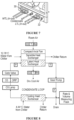
- membrane microgravity air conditioner comprises air box 10; filtering system (generally referred to as "20" and not specifically called out in the figures) disposed at least partially, and preferably substantially completely, within air box 10; particulate filter 23 disposed in inlet air flow path 15 intermediate one or more trash screens 21 and one or more latent heat exchangers (LHX) 22; thermal control system (TCS) medium temperature loop 24, comprising a coolant; and sensible heat exchanger (SHX) 25 disposed in the inlet air flow path intermediate particulate filter 23 and latent heat exchangers (LHX) 22.
- filtering system generally referred to as "20" and not specifically called out in the figures
- TCS thermal control system
- SHX sensible heat exchanger
- air box 10 may be substantially cubic and typically comprises closed bottom 11, an at least partially open top 12, and a plurality of side faces, e.g. side faces 13a-13d ( Fig. 3 ), connected to closed bottom 11 and open top 12 to define interior 14, which, as noted, is typically substantially cubic.
- At least one side face 13a of the plurality of side faces 13a-13d and open top 12 define inlet air flow path 15 from that side face, e.g. 13a through open top 12.
- four side faces 13a-13d are illustrated, fewer or greater sides can be present.
- Filtering system filtering system 20 typically comprises one or more substantially open filtering system braces 21 and one or more LHXs 22 disposed in inlet air flow path 15.
- filtering system brace 21 either secures, comprises, or both secures and comprises trash screen 21 which is disposed in inlet air flow path 15.
- filtering system 20 comprises hinge 211 disposed on an edge of filtering system 20, e.g. as part of filtering system brace 21, and attached to its associated side face 13a-13d to allow access to trash screen 21 and/or particulate filter 23 such as for periodic replacement from outside air box 10.
- each LHX 22 typically comprises one or more predetermined sets of nanoporous hydrophilic tubes 210, comprising a first end 211 and a second end 212; solid tube inlet manifold 220 in fluid communication with first end 211; and solid tube outlet manifold 230 in fluid communication with second end 212.
- Tubes 210 may act as inlet and outlet manifolds such as solid tube outlet manifold 230 may be present at first end 211 and a second end 212.
- SHX 25 typically comprises fluid inlet 251 and fluid outlet 252 plumbed in parallel into TCS medium temperature loop 24; one or more air fans 26, which may be compact axial fans, disposed in inlet air flow path 15; and power source 27 ( Fig. 2 ) operatively connected to equipment that needs power, e.g air fans 26 and/or pumps 19.
- air fan 26 which may be one or more such fans, e.g. four, is disposed intermediate LHX 22 and open top 12.
- fan panel 16 is disposed at least partially an interior of air box 10 or mounted to closed bottom or 11 open top 12 of air box 10. If present, one or more air fans 26 may also be attached or otherwise connected to fan panel 16. Also, if fan panel 16 is present, it may further comprise one or more hinges 161 disposed about an edge of fan panel 16 and configured to allow access to components inside air box 10 such as when fan panel 16 is moved about hinge 161.
- the coolant is typically comprises a 12.78°C (55° F). liquid water-glycol mixture.
- water heat exchanger 17 may be disposed within air flow 16 and operatively in fluid communication with air fan 26.
- one or more fluid meters 18 may be operatively disposed in air flow 15 intermediate water heat exchanger 17 and LHX 22.
- These fluid meters 18 may comprise a fluid flow meter, an orifice flow meter, or the like, or a combination thereof.
- Orifice flow meters if present, are typically operative to monitor water flow rate and lower water pressure of water flowing through LHX 21 below that of air flowing through LHX 21.
- one or more water sources 28 may be in fluid communication with water heat exchanger 17.
- one or more water heat exchanger coolant sources 29 may be in fluid communication with water heat exchanger 17, where each such water heat exchanger coolant source 29 may further comprise a 4.44°C (40° F). coolant or the like.
- one or more gear pumps 19, which may be pulse-free variable-speed gear pumps, may be disposed within air box 10 and operatively in fluid communication with water heat exchanger 17.
- one or more power connectors 30 configured to provide an interface to a power source such as power source 27 ( FIG. 2 ) and/or an external power source.
- a power source such as power source 27 ( FIG. 2 ) and/or an external power source.
- one or more communications data ports 32 may be present and operatively in communication a data communications network (not shown in the figures).
- cold liquid water is retained in hydrophilic pores of tubes 210 by capillary action.
- Water vapor is allowed to condense from air flowing around the outside of tubes 210 into the retained cold water.
- Water vapor is allowed to flow through the tube walls into the cold water flowing through tubes 210, in response to a small pressure difference between the air outside tubes 210 and the water inside tubes 210.
- Air is typically pulled out of open top 12 such as by one or more air fans 26, by way of example not limitation four identical air fans 26 in fan panel 16, with closed bottom 11 acting as a mounting panel.
- Hinged filtering systems 21 can allow access to trash screens 21 and/or particulate filters 23, such as for periodic replacement from outside air box 10.
- one or more SHXs 25 are plumbed in parallel into TCS medium temperature loop 24, using its coolant to remove sensible heat load from the air.
- Atmosphere dew point temperature is controlled by one or more LHXs 22 to a predetermined temperature, e.g. 12.78°C (55° F) or less, so no water condenses in SHX 25.
- Humidity is removed from SHX-cooled air and condensed into a pumped circuit of cold water via LHX 22.
- Latent heat generated in LHX 22 is transferred through WHX 17 to TCS low temperature loop 24 using its coolant to create low dew point temperature in the dehumidified air.
- WHX 17, and one or more gear pumps 19 for cold water circulation may be mounted to the inside of air box 10, along with all plumbing connecting the cold water circuit components. Since all of these plumbed components run cold, condensate would form on their exterior surfaces if mounted outside of air box 10. Since air in the air box 10 is cool and dry, surface condensation is eliminated with minimal thermal insulation.
- gear pump 19, as described above may have cool air flowing through air box 10 act as a convective heat sink for gear pump 19. Also, cool air flowing through the air box 10 acts as a convective heat sink for gear pump 19. Also, cool air flowing through the air box 10 acts as a convective heat sink for gear pump 19 motors, so motors with cooling fans are not required for microgravity compatibility.
- flow meter 18 which may comprise an orifice flow meter, is placed in the cold water circuit just upstream of LHX 22 not only monitors water flow rate, but also lowers the pressure of the water flowing through LHX 22 below that of air flowing through LHX 22.
- generated oxidants ozone and hydrogen peroxide diffuse outward through NHM pores and reduced gases diffuse inward and are destroyed by the oxidants.
- Microflora in water on the NHM air surface are killed by the disinfecting power of the oxidants, preventing biofilm growth on the NHM.
- Oxidants can only be generated in the LHX water loop photochemically, by hard UVC light from mercury vapor, xenon flash, or xenon excimer lamps.
- Electrochemical generation of oxidants requires water containing dissolved salts; LHX water has negligible dissolved salts. All three of these UVC lamp types generate both biocidal UV at about 250 nm wavelength and oxidant UV below 200 nm wavelenth.
- Xenon is a completely safe inert gas.
- Mercury vapor lamps are safely used for water disinfection and purification around the Earth, due to the fact that mercury exposure limits are higher than the vapor pressure of mercury at room temperature, and modern mercury vapor lamps have tough UV-transparent polymer coatings that contain mercury even if the lamp glass breaks.
Landscapes
- Engineering & Computer Science (AREA)
- Chemical & Material Sciences (AREA)
- Remote Sensing (AREA)
- Aviation & Aerospace Engineering (AREA)
- Chemical Kinetics & Catalysis (AREA)
- Oil, Petroleum & Natural Gas (AREA)
- General Chemical & Material Sciences (AREA)
- Analytical Chemistry (AREA)
- Health & Medical Sciences (AREA)
- Environmental Sciences (AREA)
- General Health & Medical Sciences (AREA)
- Toxicology (AREA)
- Environmental & Geological Engineering (AREA)
- Biodiversity & Conservation Biology (AREA)
- Life Sciences & Earth Sciences (AREA)
- General Engineering & Computer Science (AREA)
- Mechanical Engineering (AREA)
- Combustion & Propulsion (AREA)
- Separation Using Semi-Permeable Membranes (AREA)
- Physics & Mathematics (AREA)
- Thermal Sciences (AREA)
- Crystallography & Structural Chemistry (AREA)
Claims (14)
- Climatiseur à microgravité à membrane comportant :a. un coffre d'air (10) comportant :i. une partie inférieure fermée (11) ;ii. une partie supérieure au moins partiellement ouverte (12) ; etiii. une pluralité de côtés (13a - 13d), chaque côté comportant une face latérale, raccordés au niveau de la partie inférieure fermée et de la partie supérieure ouverte pour définir une partie intérieure (14), au moins une face latérale (13a) de la pluralité de faces latérales et la partie supérieure définissant un chemin de circulation d'air (15) depuis cette face au travers de la partie supérieure au moins partiellement ouverte ; etb. un système de filtration (20) disposé au moins partiellement à l'intérieur du coffre d'air, le système de filtration comportant :i. une contrefiche de système de filtration de type ouvert (21) ;ii. une grille à débris (21) disposée dans le chemin de circulation d'air (15) ;iii. un échangeur de chaleur latente (LHX) (22) disposé dans le chemin de circulation d'air, l'échangeur LHX comportant :1. un ensemble prédéterminé de tubes hydrophiles nanoporeux (210), comportant une première extrémité (211) et une deuxième extrémité (212) ;2. un collecteur d'entrée en tube plein (220) en communication fluidique avec la première extrémité ; et3. un collecteur de sortie en tube plein (230) en communication fluidique avec la deuxième extrémité ;iv. un filtre à particules (23) disposé dans le chemin de circulation d'air entre la grille à débris et l'échangeur LHX ;v. une boucle à température moyenne de système de régulation thermique (TCS) (24) comportant un liquide de refroidissement ;vi. un échangeur de chaleur sensible (SHX) (25) disposé dans le chemin de circulation d'air entre le filtre à particules et l'échangeur LHX, l'échangeur SHX comportant une entrée de fluide (251) et une sortie de fluide (252) raccordées en parallèle par tuyauterie dans la boucle à température moyenne TCS ;vii. un ventilateur d'air (26) disposé dans le chemin de circulation d'air ; etc. une source d'alimentation (27) raccordée fonctionnellement au niveau du ventilateur d'air (26).
- Climatiseur à microgravité à membrane selon la revendication 1, dans lequel la pluralité de côtés comporte quatre côtés.
- Climatiseur à microgravité à membrane selon la revendication 1, dans lequel la partie intérieure (14) est de forme sensiblement cubique.
- Climatiseur à microgravité à membrane selon la revendication 1, dans lequel le système de filtration (20) comporte un système de filtration (20) par chaque face de la pluralité de faces latérales (13a - 13d).
- Climatiseur à microgravité à membrane selon la revendication 1, dans lequel le système de filtration (20) comporte une articulation (211) disposée sur un bord du système de filtration (20), l'articulation étant configurée pour permettre l'accès au filtre à particules à des fins de remplacement périodique depuis l'extérieur du coffre d'air.
- Climatiseur à microgravité à membrane selon la revendication 1, dans lequel le ventilateur d'air est disposé entre l'échangeur LHX (22) et la partie supérieure ouverte (12).
- Climatiseur à microgravité à membrane selon la revendication 1, comportant par ailleurs un panneau de ventilateur (16) disposé dans la partie intérieure du coffre d'air, le ventilateur d'air (26) étant raccordé au panneau de ventilateur et, éventuellement,dans lequel le panneau de ventilateur (16) est monté sur la partie inférieure fermée, oudans lequel le panneau de ventilateur comporte une articulation (161) disposée autour d'un bord du panneau de ventilateur et configurée pour permettre l'accès à des composants dans le coffre d'air.
- Climatiseur à microgravité à membrane selon la revendication 1, comportant par ailleurs un échangeur de chaleur à eau (17) disposé à l'intérieur de la circulation d'air et fonctionnellement en communication fluidique avec le ventilateur d'air.
- Climatiseur à microgravité à membrane selon la revendication 8, comportant par ailleurs un débitmètre de fluide (18) disposé fonctionnellement dans la circulation d'air entre l'échangeur de chaleur à eau et l'échangeur LHX et, éventuellement,dans lequel le débitmètre de fluide (18) comporte un débitmètre de circulation de fluide (18b) disposé en amont de l'échangeur LHX ou un débitmètre de circulation d'orifice, disposé en amont de l'échangeur LHX et fonctionnant pour surveiller le débit de circulation de l'eau et fonctionnant pour abaisser la pression d'eau de l'eau circulant au travers de l'échangeur LHX à une pression inférieure à la pression de l'air circulant au travers de l'échangeur LHX et, éventuellement,comportant par ailleurs une pompe à engrenages (19) disposée à l'intérieur du coffre d'air et fonctionnellement en communication fluidique avec l'échangeur de chaleur à eau.
- Climatiseur à microgravité à membrane selon la revendication 8, comportant par ailleurs :a. une source d'eau (28) en communication fluidique avec l'échangeur de chaleur à eau ; etb. une source de liquide de refroidissement d'échangeur de chaleur à eau (29) en communication fluidique avec l'échangeur de chaleur à eau.
- Climatiseur à microgravité à membrane selon la revendication 1, dans lequel la source d'alimentation comporte un connecteur d'alimentation (30) configuré pour fournir une interface avec une source d'alimentation externe.
- Climatiseur à microgravité à membrane selon la revendication 1, comportant par ailleurs un port de données de communication (32) fonctionnellement en communication avec un réseau de communication de données.
- Procédé servant à mettre en oeuvre une production de condensat propre à partir de l'humidité dans de l'air non filtré pendant une durée prolongée au moyen d'un climatiseur à microgravité à membrane, le climatiseur à microgravité à membrane comportant un coffre d'air comportant une partie inférieure fermée, une partie supérieure au moins partiellement ouverte, et une pluralité de faces raccordées à la partie inférieure fermée et à la partie supérieure ouverte pour définir une partie intérieure, une face de la pluralité de faces et la partie supérieure au moins partiellement ouverte définissant un chemin de circulation d'air depuis cette face au travers de la partie supérieure ouverte, et un système de filtration disposé à l'intérieur du coffre d'air, le système de filtration comportant une grille à débris disposée dans le chemin de circulation d'air, un échangeur de chaleur latente (LHX) disposé dans le chemin de circulation d'air, un filtre à particules disposé dans le chemin de circulation d'air entre la grille à débris et l'échangeur LHX, une boucle à température moyenne de système de régulation thermique (TCS) comportant un liquide de refroidissement, un échangeur de chaleur sensible (SHX) disposé dans le chemin de circulation d'air entre le filtre à particules et l'échangeur LHX, l'échangeur SHX étant raccordé en parallèle par tuyauterie dans la boucle à température moyenne de système de régulation thermique (TCS), un ventilateur disposé dans le chemin de circulation d'air, et une source d'alimentation raccordée fonctionnellement au ventilateur, le procédé comportant les étapes consistant à :a. retenir de l'eau liquide froide dans des pores hydrophiles des tubes par action capillaire ;b. permettre à la vapeur d'eau de se condenser à partir de l'air circulant autour de l'extérieur des tubes en eau liquide froide retenue ; etc. permettre à la vapeur d'eau de circuler au travers des parois des tubes dans l'eau liquide froide circulant dans les tubes, en réponse à la faible différence de pression entre l'air à l'extérieur des tubes et l'eau à l'intérieur des tubes.
- Procédé selon la revendication 13, dans lequel le climatiseur à microgravité à membrane comporte par ailleurs une pompe à engrenages disposée à l'intérieur du coffre d'air et fonctionnellement en communication fluidique avec l'échangeur de chaleur à eau, le procédé comportant par ailleurs l'étape consistant à permettre à l'air refroidi circulant au travers du coffre d'air d'agir comme source de froid par convection pour la pompe à engrenages.
Applications Claiming Priority (2)
| Application Number | Priority Date | Filing Date | Title |
|---|---|---|---|
| US201662315951P | 2016-03-31 | 2016-03-31 | |
| PCT/US2017/025322 WO2017173239A1 (fr) | 2016-03-31 | 2017-03-31 | Climatiseur à microgravité à membrane |
Publications (3)
| Publication Number | Publication Date |
|---|---|
| EP3436181A1 EP3436181A1 (fr) | 2019-02-06 |
| EP3436181A4 EP3436181A4 (fr) | 2020-02-26 |
| EP3436181B1 true EP3436181B1 (fr) | 2023-08-09 |
Family
ID=59959227
Family Applications (1)
| Application Number | Title | Priority Date | Filing Date |
|---|---|---|---|
| EP17776757.1A Active EP3436181B1 (fr) | 2016-03-31 | 2017-03-31 | Climatiseur à microgravité à membrane |
Country Status (3)
| Country | Link |
|---|---|
| US (1) | US10287037B2 (fr) |
| EP (1) | EP3436181B1 (fr) |
| WO (1) | WO2017173239A1 (fr) |
Families Citing this family (12)
| Publication number | Priority date | Publication date | Assignee | Title |
|---|---|---|---|---|
| WO2018217172A1 (fr) * | 2017-05-24 | 2018-11-29 | Singapore Power Limited | Procédé et système de gestion de charge de refroidissement |
| US11286064B2 (en) * | 2018-02-21 | 2022-03-29 | Genesis Engineering Solutions, Inc. | Single-person spacecraft |
| CA3009337A1 (fr) | 2018-06-26 | 2019-12-26 | Copper Core Limited | Ensemble echangeur de chaleur avec un ruban de protection thermique |
| IL263915B (en) * | 2018-12-23 | 2022-03-01 | Beth El Zikhron Yaaqov Ind Ltd | Filtration systems |
| US20220153456A1 (en) * | 2020-11-13 | 2022-05-19 | Hamilton Sundstrand Corporation | Integrated condensing heat exchanger and water separator |
| CN112682498B (zh) * | 2020-12-24 | 2022-06-03 | 扬中市正伟电器制造有限公司 | 一种制冷机用减速器散热机构及其散热方法 |
| CN112357126B (zh) * | 2021-01-11 | 2021-03-30 | 中国人民解放军国防科技大学 | 有害气体去除单元贮存装置 |
| CN115776796A (zh) * | 2021-09-06 | 2023-03-10 | 英业达科技有限公司 | 散热组件以及电子组件 |
| CN115768034A (zh) * | 2021-09-06 | 2023-03-07 | 英业达科技有限公司 | 冷凝器 |
| US20230076784A1 (en) * | 2021-09-06 | 2023-03-09 | Inventec (Pudong) Technology Corporation | Heat dissipation assembly and electronic assembly |
| CN115569432B (zh) * | 2022-08-31 | 2025-01-10 | 北京空间飞行器总体设计部 | 一种适用于微重力条件的热泵系统用储液过滤器 |
| DE112023000043B4 (de) | 2022-09-13 | 2024-12-19 | Dongguan Orion Machinery Co., Ltd. | Kaltwasserzufuhrvorrichtungseinheit mit Druckluftentfeuchtungsvorrichtung |
Family Cites Families (32)
| Publication number | Priority date | Publication date | Assignee | Title |
|---|---|---|---|---|
| DE19910441C1 (de) * | 1999-03-10 | 2000-06-21 | Fraunhofer Ges Forschung | Luftbefeuchtung |
| US2638644A (en) * | 1947-10-25 | 1953-05-19 | John R Rauhut | Air-conditioning and humidifying apparatus |
| DE2944027A1 (de) * | 1970-07-22 | 1981-05-07 | Erevanskyj politechničeskyj institut imeni Karla Marksa, Erewan | Ejektor-raumklimageraet der zentral-klimaanlage |
| US4023949A (en) * | 1975-08-04 | 1977-05-17 | Schlom Leslie A | Evaporative refrigeration system |
| US4090370A (en) * | 1976-03-11 | 1978-05-23 | Vaughan Kenneth F | Environmental control system |
| DE3100915C2 (de) * | 1980-05-26 | 1986-08-07 | Sharp K.K., Osaka | Klimagerät für Umluftbetrieb |
| JPH0611160A (ja) * | 1992-04-30 | 1994-01-21 | Komatsu Ltd | 加湿器及びそれに使用される中空糸体 |
| US5368786A (en) * | 1992-09-30 | 1994-11-29 | Wisconsin Alumni Research Foundation | Apparatus and methods for humidity control |
| US6149810A (en) * | 1994-11-23 | 2000-11-21 | Lynntech, Inc. | Membrane with supported internal passages |
| US5555732A (en) * | 1995-02-09 | 1996-09-17 | Whiticar; John | Portable dehumidifier |
| CN1094581C (zh) * | 1996-04-04 | 2002-11-20 | 童夏民 | 一种空调机 |
| US6237352B1 (en) * | 1999-08-18 | 2001-05-29 | Winton J. Goodchild | Water producing and dispensing machine |
| AU2013205382A1 (en) * | 2005-07-29 | 2013-05-23 | Freedom Water Company Ltd. | Water condenser |
| WO2007012202A1 (fr) * | 2005-07-29 | 2007-02-01 | Freedom Water Company Ltd. | Condenseur d'eau |
| US20090010801A1 (en) * | 2007-05-15 | 2009-01-08 | Murphy Oliver J | Air cleaner |
| JP5396705B2 (ja) * | 2007-10-31 | 2014-01-22 | ダイキン工業株式会社 | 調湿装置 |
| US20090158928A1 (en) * | 2007-12-19 | 2009-06-25 | Whirlpool Corporation | Squeezable moisture removal device |
| WO2009129517A1 (fr) * | 2008-04-18 | 2009-10-22 | Jarrell Wenger | Amélioration de tours de refroidissement par évaporation par récupération de refroidissement |
| WO2010010576A1 (fr) * | 2008-07-22 | 2010-01-28 | Sumaya Hmx Systems Private Limited | Systèmes et procédés pour refroidissement par évaporation indirecte et pour refroidissement par évaporation en deux étapes |
| US20120037342A1 (en) * | 2009-02-11 | 2012-02-16 | Mathew Holloway | Fluid conditioning arrangements |
| WO2012033827A1 (fr) * | 2010-09-07 | 2012-03-15 | Dais Analytic Corporation | Systèmes et procédés de traitement de fluide au moyen de membranes de transfert sélectif |
| US8678359B2 (en) * | 2010-12-23 | 2014-03-25 | Yahoo! Inc. | System and method for reducing mineral buildup on drift eliminators of a cooling tower |
| US9067087B2 (en) * | 2012-08-30 | 2015-06-30 | Oceaneering International, Inc. | Membrane-enabled reverse lung |
| JP5989236B2 (ja) * | 2013-04-22 | 2016-09-07 | 三菱電機株式会社 | 加湿装置及び加湿装置を備えた空気調和機 |
| WO2015040910A1 (fr) * | 2013-09-18 | 2015-03-26 | 三菱電機株式会社 | Dispositif d'humidification et climatiseur comprenant un dispositif d'humidification |
| US20150128807A1 (en) * | 2013-11-13 | 2015-05-14 | Dexwet International AG | Synthetic Injected Hydrophilic Filter System |
| US10132577B2 (en) * | 2014-01-20 | 2018-11-20 | Baltimore Aircoil Company, Inc. | Adiabatic refrigerant condenser controls system |
| CA2937943A1 (fr) * | 2014-02-12 | 2015-08-20 | Praxair Technology, Inc. | Procede a base de reacteur a membrane de transport d'oxygene et systeme pour la production d'energie electrique |
| US20150253046A1 (en) * | 2014-03-07 | 2015-09-10 | University Of Central Florida Research Foundation, Inc. | Evaporatively cooled mini-split air conditioning system |
| WO2016021850A1 (fr) * | 2014-08-07 | 2016-02-11 | 한양대학교에리카산학협력단 | Dispositif de déshumidification et d'humidification |
| AU2015316185B2 (en) * | 2014-09-08 | 2021-02-04 | Ff Seeley Nominees Pty Ltd | Compact indirect evaporative cooler |
| JP2016176674A (ja) * | 2015-03-23 | 2016-10-06 | 株式会社東芝 | 水回収システム、加湿システムおよび空気調和システム |
-
2017
- 2017-03-31 US US15/475,580 patent/US10287037B2/en active Active - Reinstated
- 2017-03-31 WO PCT/US2017/025322 patent/WO2017173239A1/fr not_active Ceased
- 2017-03-31 EP EP17776757.1A patent/EP3436181B1/fr active Active
Also Published As
| Publication number | Publication date |
|---|---|
| EP3436181A4 (fr) | 2020-02-26 |
| US20170284751A1 (en) | 2017-10-05 |
| EP3436181A1 (fr) | 2019-02-06 |
| WO2017173239A1 (fr) | 2017-10-05 |
| US10287037B2 (en) | 2019-05-14 |
Similar Documents
| Publication | Publication Date | Title |
|---|---|---|
| EP3436181B1 (fr) | Climatiseur à microgravité à membrane | |
| US11737239B2 (en) | Blended operation mode for providing cooling to a heat load | |
| CN102859083B (zh) | 用于从空气中提取水的装置和用于生产饮用水的系统和设备 | |
| FI108962B (fi) | Laitekaapin jäähdytysjärjestelmä | |
| US10260818B2 (en) | Cooling system and method of cooling an interior space | |
| CN204234107U (zh) | 试验箱 | |
| BRPI0614319A2 (pt) | condensador de água, método para condensar água, método para controlar um condensador de água, sistema de controle e evaporador para um condensador de água, método para evaporar água, trocador de calor para um condensador de água, e, método para limpar um condensador de água | |
| KR102292466B1 (ko) | Ai 제어 기반 고효율 통합공조장치 | |
| JP6505551B2 (ja) | クリーンルーム用排気ユニット | |
| CA2451496C (fr) | Ensemble d'eclairage ultraviolet | |
| KR101548328B1 (ko) | 서버실 냉각 장치 및 이를 구비하는 데이터 센터의 공조 시스템의 제조 방법 | |
| EP2568169B2 (fr) | Éolienne dotée d'un système de climatisation en forme de tour utilisant de l'air extérieur | |
| US6817206B2 (en) | Air conditioning apparatus for isolated spaces | |
| EP4194763A1 (fr) | Systèmes et procédés de gestion de conditions dans un espace clos | |
| JP5660075B2 (ja) | 空調換気装置 | |
| KR20150122578A (ko) | 서버실 냉각 장치 및 이를 구비하는 데이터 센터의 공조 시스템의 제조 방법 | |
| US20230130691A1 (en) | Baffle strainer system and method | |
| KR20210118493A (ko) | 차압 센서를 구비한 환기 장치 | |
| EP4455561A1 (fr) | Appareil de réglage de température de piscine | |
| WO2023115643A1 (fr) | Appareil de réglage de température de piscine | |
| KR20160043943A (ko) | 서버실 냉각 장치 및 이를 구비하는 데이터 센터의 공조 시스템 | |
| CN211822806U (zh) | 空调加湿系统及空调器 | |
| KR20150081729A (ko) | 서버실 냉각 장치 및 이를 구비하는 데이터 센터의 공조 시스템 | |
| CN106440116B (zh) | 一种除湿系统及其控制方法 | |
| WO2022013748A1 (fr) | Système de traitement des fluides basé sur un humidificateur-déshumidificateur |
Legal Events
| Date | Code | Title | Description |
|---|---|---|---|
| STAA | Information on the status of an ep patent application or granted ep patent |
Free format text: STATUS: THE INTERNATIONAL PUBLICATION HAS BEEN MADE |
|
| PUAI | Public reference made under article 153(3) epc to a published international application that has entered the european phase |
Free format text: ORIGINAL CODE: 0009012 |
|
| STAA | Information on the status of an ep patent application or granted ep patent |
Free format text: STATUS: REQUEST FOR EXAMINATION WAS MADE |
|
| 17P | Request for examination filed |
Effective date: 20180926 |
|
| AK | Designated contracting states |
Kind code of ref document: A1 Designated state(s): AL AT BE BG CH CY CZ DE DK EE ES FI FR GB GR HR HU IE IS IT LI LT LU LV MC MK MT NL NO PL PT RO RS SE SI SK SM TR |
|
| AX | Request for extension of the european patent |
Extension state: BA ME |
|
| DAV | Request for validation of the european patent (deleted) | ||
| DAX | Request for extension of the european patent (deleted) | ||
| A4 | Supplementary search report drawn up and despatched |
Effective date: 20200123 |
|
| RIC1 | Information provided on ipc code assigned before grant |
Ipc: A62B 13/00 20060101ALI20200117BHEP Ipc: B64G 1/48 20060101ALI20200117BHEP Ipc: B01D 53/22 20060101AFI20200117BHEP Ipc: B01D 53/26 20060101ALI20200117BHEP Ipc: F24F 3/14 20060101ALI20200117BHEP |
|
| STAA | Information on the status of an ep patent application or granted ep patent |
Free format text: STATUS: EXAMINATION IS IN PROGRESS |
|
| 17Q | First examination report despatched |
Effective date: 20220419 |
|
| GRAP | Despatch of communication of intention to grant a patent |
Free format text: ORIGINAL CODE: EPIDOSNIGR1 |
|
| STAA | Information on the status of an ep patent application or granted ep patent |
Free format text: STATUS: GRANT OF PATENT IS INTENDED |
|
| INTG | Intention to grant announced |
Effective date: 20230228 |
|
| GRAS | Grant fee paid |
Free format text: ORIGINAL CODE: EPIDOSNIGR3 |
|
| P01 | Opt-out of the competence of the unified patent court (upc) registered |
Effective date: 20230526 |
|
| GRAA | (expected) grant |
Free format text: ORIGINAL CODE: 0009210 |
|
| STAA | Information on the status of an ep patent application or granted ep patent |
Free format text: STATUS: THE PATENT HAS BEEN GRANTED |
|
| AK | Designated contracting states |
Kind code of ref document: B1 Designated state(s): AL AT BE BG CH CY CZ DE DK EE ES FI FR GB GR HR HU IE IS IT LI LT LU LV MC MK MT NL NO PL PT RO RS SE SI SK SM TR |
|
| REG | Reference to a national code |
Ref country code: GB Ref legal event code: FG4D |
|
| REG | Reference to a national code |
Ref country code: CH Ref legal event code: EP |
|
| REG | Reference to a national code |
Ref country code: IE Ref legal event code: FG4D |
|
| REG | Reference to a national code |
Ref country code: DE Ref legal event code: R096 Ref document number: 602017072492 Country of ref document: DE |
|
| REG | Reference to a national code |
Ref country code: LT Ref legal event code: MG9D |
|
| REG | Reference to a national code |
Ref country code: NL Ref legal event code: MP Effective date: 20230809 |
|
| REG | Reference to a national code |
Ref country code: AT Ref legal event code: MK05 Ref document number: 1596842 Country of ref document: AT Kind code of ref document: T Effective date: 20230809 |
|
| PG25 | Lapsed in a contracting state [announced via postgrant information from national office to epo] |
Ref country code: GR Free format text: LAPSE BECAUSE OF FAILURE TO SUBMIT A TRANSLATION OF THE DESCRIPTION OR TO PAY THE FEE WITHIN THE PRESCRIBED TIME-LIMIT Effective date: 20231110 |
|
| PG25 | Lapsed in a contracting state [announced via postgrant information from national office to epo] |
Ref country code: IS Free format text: LAPSE BECAUSE OF FAILURE TO SUBMIT A TRANSLATION OF THE DESCRIPTION OR TO PAY THE FEE WITHIN THE PRESCRIBED TIME-LIMIT Effective date: 20231209 |
|
| PG25 | Lapsed in a contracting state [announced via postgrant information from national office to epo] |
Ref country code: SE Free format text: LAPSE BECAUSE OF FAILURE TO SUBMIT A TRANSLATION OF THE DESCRIPTION OR TO PAY THE FEE WITHIN THE PRESCRIBED TIME-LIMIT Effective date: 20230809 Ref country code: RS Free format text: LAPSE BECAUSE OF FAILURE TO SUBMIT A TRANSLATION OF THE DESCRIPTION OR TO PAY THE FEE WITHIN THE PRESCRIBED TIME-LIMIT Effective date: 20230809 Ref country code: PT Free format text: LAPSE BECAUSE OF FAILURE TO SUBMIT A TRANSLATION OF THE DESCRIPTION OR TO PAY THE FEE WITHIN THE PRESCRIBED TIME-LIMIT Effective date: 20231211 Ref country code: NO Free format text: LAPSE BECAUSE OF FAILURE TO SUBMIT A TRANSLATION OF THE DESCRIPTION OR TO PAY THE FEE WITHIN THE PRESCRIBED TIME-LIMIT Effective date: 20231109 Ref country code: NL Free format text: LAPSE BECAUSE OF FAILURE TO SUBMIT A TRANSLATION OF THE DESCRIPTION OR TO PAY THE FEE WITHIN THE PRESCRIBED TIME-LIMIT Effective date: 20230809 Ref country code: LV Free format text: LAPSE BECAUSE OF FAILURE TO SUBMIT A TRANSLATION OF THE DESCRIPTION OR TO PAY THE FEE WITHIN THE PRESCRIBED TIME-LIMIT Effective date: 20230809 Ref country code: LT Free format text: LAPSE BECAUSE OF FAILURE TO SUBMIT A TRANSLATION OF THE DESCRIPTION OR TO PAY THE FEE WITHIN THE PRESCRIBED TIME-LIMIT Effective date: 20230809 Ref country code: IS Free format text: LAPSE BECAUSE OF FAILURE TO SUBMIT A TRANSLATION OF THE DESCRIPTION OR TO PAY THE FEE WITHIN THE PRESCRIBED TIME-LIMIT Effective date: 20231209 Ref country code: HR Free format text: LAPSE BECAUSE OF FAILURE TO SUBMIT A TRANSLATION OF THE DESCRIPTION OR TO PAY THE FEE WITHIN THE PRESCRIBED TIME-LIMIT Effective date: 20230809 Ref country code: GR Free format text: LAPSE BECAUSE OF FAILURE TO SUBMIT A TRANSLATION OF THE DESCRIPTION OR TO PAY THE FEE WITHIN THE PRESCRIBED TIME-LIMIT Effective date: 20231110 Ref country code: FI Free format text: LAPSE BECAUSE OF FAILURE TO SUBMIT A TRANSLATION OF THE DESCRIPTION OR TO PAY THE FEE WITHIN THE PRESCRIBED TIME-LIMIT Effective date: 20230809 Ref country code: AT Free format text: LAPSE BECAUSE OF FAILURE TO SUBMIT A TRANSLATION OF THE DESCRIPTION OR TO PAY THE FEE WITHIN THE PRESCRIBED TIME-LIMIT Effective date: 20230809 |
|
| PG25 | Lapsed in a contracting state [announced via postgrant information from national office to epo] |
Ref country code: PL Free format text: LAPSE BECAUSE OF FAILURE TO SUBMIT A TRANSLATION OF THE DESCRIPTION OR TO PAY THE FEE WITHIN THE PRESCRIBED TIME-LIMIT Effective date: 20230809 |
|
| PG25 | Lapsed in a contracting state [announced via postgrant information from national office to epo] |
Ref country code: ES Free format text: LAPSE BECAUSE OF FAILURE TO SUBMIT A TRANSLATION OF THE DESCRIPTION OR TO PAY THE FEE WITHIN THE PRESCRIBED TIME-LIMIT Effective date: 20230809 |
|
| PG25 | Lapsed in a contracting state [announced via postgrant information from national office to epo] |
Ref country code: SM Free format text: LAPSE BECAUSE OF FAILURE TO SUBMIT A TRANSLATION OF THE DESCRIPTION OR TO PAY THE FEE WITHIN THE PRESCRIBED TIME-LIMIT Effective date: 20230809 Ref country code: RO Free format text: LAPSE BECAUSE OF FAILURE TO SUBMIT A TRANSLATION OF THE DESCRIPTION OR TO PAY THE FEE WITHIN THE PRESCRIBED TIME-LIMIT Effective date: 20230809 Ref country code: ES Free format text: LAPSE BECAUSE OF FAILURE TO SUBMIT A TRANSLATION OF THE DESCRIPTION OR TO PAY THE FEE WITHIN THE PRESCRIBED TIME-LIMIT Effective date: 20230809 Ref country code: EE Free format text: LAPSE BECAUSE OF FAILURE TO SUBMIT A TRANSLATION OF THE DESCRIPTION OR TO PAY THE FEE WITHIN THE PRESCRIBED TIME-LIMIT Effective date: 20230809 Ref country code: DK Free format text: LAPSE BECAUSE OF FAILURE TO SUBMIT A TRANSLATION OF THE DESCRIPTION OR TO PAY THE FEE WITHIN THE PRESCRIBED TIME-LIMIT Effective date: 20230809 Ref country code: CZ Free format text: LAPSE BECAUSE OF FAILURE TO SUBMIT A TRANSLATION OF THE DESCRIPTION OR TO PAY THE FEE WITHIN THE PRESCRIBED TIME-LIMIT Effective date: 20230809 Ref country code: SK Free format text: LAPSE BECAUSE OF FAILURE TO SUBMIT A TRANSLATION OF THE DESCRIPTION OR TO PAY THE FEE WITHIN THE PRESCRIBED TIME-LIMIT Effective date: 20230809 |
|
| REG | Reference to a national code |
Ref country code: DE Ref legal event code: R097 Ref document number: 602017072492 Country of ref document: DE |
|
| PLBE | No opposition filed within time limit |
Free format text: ORIGINAL CODE: 0009261 |
|
| STAA | Information on the status of an ep patent application or granted ep patent |
Free format text: STATUS: NO OPPOSITION FILED WITHIN TIME LIMIT |
|
| 26N | No opposition filed |
Effective date: 20240513 |
|
| PG25 | Lapsed in a contracting state [announced via postgrant information from national office to epo] |
Ref country code: SI Free format text: LAPSE BECAUSE OF FAILURE TO SUBMIT A TRANSLATION OF THE DESCRIPTION OR TO PAY THE FEE WITHIN THE PRESCRIBED TIME-LIMIT Effective date: 20230809 |
|
| REG | Reference to a national code |
Ref country code: CH Ref legal event code: PL |
|
| PG25 | Lapsed in a contracting state [announced via postgrant information from national office to epo] |
Ref country code: BG Free format text: LAPSE BECAUSE OF FAILURE TO SUBMIT A TRANSLATION OF THE DESCRIPTION OR TO PAY THE FEE WITHIN THE PRESCRIBED TIME-LIMIT Effective date: 20230809 |
|
| PG25 | Lapsed in a contracting state [announced via postgrant information from national office to epo] |
Ref country code: LU Free format text: LAPSE BECAUSE OF NON-PAYMENT OF DUE FEES Effective date: 20240331 |
|
| PG25 | Lapsed in a contracting state [announced via postgrant information from national office to epo] |
Ref country code: MC Free format text: LAPSE BECAUSE OF FAILURE TO SUBMIT A TRANSLATION OF THE DESCRIPTION OR TO PAY THE FEE WITHIN THE PRESCRIBED TIME-LIMIT Effective date: 20230809 |
|
| PG25 | Lapsed in a contracting state [announced via postgrant information from national office to epo] |
Ref country code: MC Free format text: LAPSE BECAUSE OF FAILURE TO SUBMIT A TRANSLATION OF THE DESCRIPTION OR TO PAY THE FEE WITHIN THE PRESCRIBED TIME-LIMIT Effective date: 20230809 Ref country code: LU Free format text: LAPSE BECAUSE OF NON-PAYMENT OF DUE FEES Effective date: 20240331 Ref country code: BG Free format text: LAPSE BECAUSE OF FAILURE TO SUBMIT A TRANSLATION OF THE DESCRIPTION OR TO PAY THE FEE WITHIN THE PRESCRIBED TIME-LIMIT Effective date: 20230809 |
|
| REG | Reference to a national code |
Ref country code: BE Ref legal event code: MM Effective date: 20240331 |
|
| PG25 | Lapsed in a contracting state [announced via postgrant information from national office to epo] |
Ref country code: BE Free format text: LAPSE BECAUSE OF NON-PAYMENT OF DUE FEES Effective date: 20240331 |
|
| PG25 | Lapsed in a contracting state [announced via postgrant information from national office to epo] |
Ref country code: IE Free format text: LAPSE BECAUSE OF NON-PAYMENT OF DUE FEES Effective date: 20240331 |
|
| PG25 | Lapsed in a contracting state [announced via postgrant information from national office to epo] |
Ref country code: IE Free format text: LAPSE BECAUSE OF NON-PAYMENT OF DUE FEES Effective date: 20240331 Ref country code: BE Free format text: LAPSE BECAUSE OF NON-PAYMENT OF DUE FEES Effective date: 20240331 Ref country code: CH Free format text: LAPSE BECAUSE OF NON-PAYMENT OF DUE FEES Effective date: 20240331 |
|
| PGFP | Annual fee paid to national office [announced via postgrant information from national office to epo] |
Ref country code: DE Payment date: 20250521 Year of fee payment: 9 |
|
| PGFP | Annual fee paid to national office [announced via postgrant information from national office to epo] |
Ref country code: GB Payment date: 20250522 Year of fee payment: 9 |
|
| PGFP | Annual fee paid to national office [announced via postgrant information from national office to epo] |
Ref country code: IT Payment date: 20250528 Year of fee payment: 9 |
|
| PGFP | Annual fee paid to national office [announced via postgrant information from national office to epo] |
Ref country code: FR Payment date: 20250530 Year of fee payment: 9 |
|
| PG25 | Lapsed in a contracting state [announced via postgrant information from national office to epo] |
Ref country code: CY Free format text: LAPSE BECAUSE OF FAILURE TO SUBMIT A TRANSLATION OF THE DESCRIPTION OR TO PAY THE FEE WITHIN THE PRESCRIBED TIME-LIMIT; INVALID AB INITIO Effective date: 20170331 |
|
| PG25 | Lapsed in a contracting state [announced via postgrant information from national office to epo] |
Ref country code: HU Free format text: LAPSE BECAUSE OF FAILURE TO SUBMIT A TRANSLATION OF THE DESCRIPTION OR TO PAY THE FEE WITHIN THE PRESCRIBED TIME-LIMIT; INVALID AB INITIO Effective date: 20170331 |
|
| PG25 | Lapsed in a contracting state [announced via postgrant information from national office to epo] |
Ref country code: TR Free format text: LAPSE BECAUSE OF FAILURE TO SUBMIT A TRANSLATION OF THE DESCRIPTION OR TO PAY THE FEE WITHIN THE PRESCRIBED TIME-LIMIT Effective date: 20230809 |