EP3436241B1 - Système d'impression tridimensionnelle - Google Patents
Système d'impression tridimensionnelle Download PDFInfo
- Publication number
- EP3436241B1 EP3436241B1 EP16910749.7A EP16910749A EP3436241B1 EP 3436241 B1 EP3436241 B1 EP 3436241B1 EP 16910749 A EP16910749 A EP 16910749A EP 3436241 B1 EP3436241 B1 EP 3436241B1
- Authority
- EP
- European Patent Office
- Prior art keywords
- print job
- removable unit
- processing station
- material processing
- coupling
- Prior art date
- Legal status (The legal status is an assumption and is not a legal conclusion. Google has not performed a legal analysis and makes no representation as to the accuracy of the status listed.)
- Active
Links
Images




Classifications
-
- B—PERFORMING OPERATIONS; TRANSPORTING
- B29—WORKING OF PLASTICS; WORKING OF SUBSTANCES IN A PLASTIC STATE IN GENERAL
- B29C—SHAPING OR JOINING OF PLASTICS; SHAPING OF MATERIAL IN A PLASTIC STATE, NOT OTHERWISE PROVIDED FOR; AFTER-TREATMENT OF THE SHAPED PRODUCTS, e.g. REPAIRING
- B29C64/00—Additive manufacturing, i.e. manufacturing of three-dimensional [3D] objects by additive deposition, additive agglomeration or additive layering, e.g. by 3D printing, stereolithography or selective laser sintering
- B29C64/20—Apparatus for additive manufacturing; Details thereof or accessories therefor
- B29C64/255—Enclosures for the building material, e.g. powder containers
- B29C64/259—Interchangeable
-
- B—PERFORMING OPERATIONS; TRANSPORTING
- B29—WORKING OF PLASTICS; WORKING OF SUBSTANCES IN A PLASTIC STATE IN GENERAL
- B29C—SHAPING OR JOINING OF PLASTICS; SHAPING OF MATERIAL IN A PLASTIC STATE, NOT OTHERWISE PROVIDED FOR; AFTER-TREATMENT OF THE SHAPED PRODUCTS, e.g. REPAIRING
- B29C64/00—Additive manufacturing, i.e. manufacturing of three-dimensional [3D] objects by additive deposition, additive agglomeration or additive layering, e.g. by 3D printing, stereolithography or selective laser sintering
- B29C64/30—Auxiliary operations or equipment
- B29C64/386—Data acquisition or data processing for additive manufacturing
- B29C64/393—Data acquisition or data processing for additive manufacturing for controlling or regulating additive manufacturing processes
-
- B—PERFORMING OPERATIONS; TRANSPORTING
- B29—WORKING OF PLASTICS; WORKING OF SUBSTANCES IN A PLASTIC STATE IN GENERAL
- B29C—SHAPING OR JOINING OF PLASTICS; SHAPING OF MATERIAL IN A PLASTIC STATE, NOT OTHERWISE PROVIDED FOR; AFTER-TREATMENT OF THE SHAPED PRODUCTS, e.g. REPAIRING
- B29C64/00—Additive manufacturing, i.e. manufacturing of three-dimensional [3D] objects by additive deposition, additive agglomeration or additive layering, e.g. by 3D printing, stereolithography or selective laser sintering
- B29C64/20—Apparatus for additive manufacturing; Details thereof or accessories therefor
- B29C64/205—Means for applying layers
- B29C64/209—Heads; Nozzles
-
- B—PERFORMING OPERATIONS; TRANSPORTING
- B29—WORKING OF PLASTICS; WORKING OF SUBSTANCES IN A PLASTIC STATE IN GENERAL
- B29C—SHAPING OR JOINING OF PLASTICS; SHAPING OF MATERIAL IN A PLASTIC STATE, NOT OTHERWISE PROVIDED FOR; AFTER-TREATMENT OF THE SHAPED PRODUCTS, e.g. REPAIRING
- B29C64/00—Additive manufacturing, i.e. manufacturing of three-dimensional [3D] objects by additive deposition, additive agglomeration or additive layering, e.g. by 3D printing, stereolithography or selective laser sintering
- B29C64/20—Apparatus for additive manufacturing; Details thereof or accessories therefor
- B29C64/255—Enclosures for the building material, e.g. powder containers
-
- B—PERFORMING OPERATIONS; TRANSPORTING
- B29—WORKING OF PLASTICS; WORKING OF SUBSTANCES IN A PLASTIC STATE IN GENERAL
- B29C—SHAPING OR JOINING OF PLASTICS; SHAPING OF MATERIAL IN A PLASTIC STATE, NOT OTHERWISE PROVIDED FOR; AFTER-TREATMENT OF THE SHAPED PRODUCTS, e.g. REPAIRING
- B29C64/00—Additive manufacturing, i.e. manufacturing of three-dimensional [3D] objects by additive deposition, additive agglomeration or additive layering, e.g. by 3D printing, stereolithography or selective laser sintering
- B29C64/20—Apparatus for additive manufacturing; Details thereof or accessories therefor
- B29C64/264—Arrangements for irradiation
-
- B—PERFORMING OPERATIONS; TRANSPORTING
- B29—WORKING OF PLASTICS; WORKING OF SUBSTANCES IN A PLASTIC STATE IN GENERAL
- B29C—SHAPING OR JOINING OF PLASTICS; SHAPING OF MATERIAL IN A PLASTIC STATE, NOT OTHERWISE PROVIDED FOR; AFTER-TREATMENT OF THE SHAPED PRODUCTS, e.g. REPAIRING
- B29C64/00—Additive manufacturing, i.e. manufacturing of three-dimensional [3D] objects by additive deposition, additive agglomeration or additive layering, e.g. by 3D printing, stereolithography or selective laser sintering
- B29C64/30—Auxiliary operations or equipment
- B29C64/307—Handling of material to be used in additive manufacturing
-
- B—PERFORMING OPERATIONS; TRANSPORTING
- B29—WORKING OF PLASTICS; WORKING OF SUBSTANCES IN A PLASTIC STATE IN GENERAL
- B29C—SHAPING OR JOINING OF PLASTICS; SHAPING OF MATERIAL IN A PLASTIC STATE, NOT OTHERWISE PROVIDED FOR; AFTER-TREATMENT OF THE SHAPED PRODUCTS, e.g. REPAIRING
- B29C64/00—Additive manufacturing, i.e. manufacturing of three-dimensional [3D] objects by additive deposition, additive agglomeration or additive layering, e.g. by 3D printing, stereolithography or selective laser sintering
- B29C64/30—Auxiliary operations or equipment
- B29C64/307—Handling of material to be used in additive manufacturing
- B29C64/321—Feeding
-
- B—PERFORMING OPERATIONS; TRANSPORTING
- B29—WORKING OF PLASTICS; WORKING OF SUBSTANCES IN A PLASTIC STATE IN GENERAL
- B29C—SHAPING OR JOINING OF PLASTICS; SHAPING OF MATERIAL IN A PLASTIC STATE, NOT OTHERWISE PROVIDED FOR; AFTER-TREATMENT OF THE SHAPED PRODUCTS, e.g. REPAIRING
- B29C64/00—Additive manufacturing, i.e. manufacturing of three-dimensional [3D] objects by additive deposition, additive agglomeration or additive layering, e.g. by 3D printing, stereolithography or selective laser sintering
- B29C64/30—Auxiliary operations or equipment
- B29C64/307—Handling of material to be used in additive manufacturing
- B29C64/321—Feeding
- B29C64/336—Feeding of two or more materials
-
- B—PERFORMING OPERATIONS; TRANSPORTING
- B33—ADDITIVE MANUFACTURING TECHNOLOGY
- B33Y—ADDITIVE MANUFACTURING, i.e. MANUFACTURING OF THREE-DIMENSIONAL [3D] OBJECTS BY ADDITIVE DEPOSITION, ADDITIVE AGGLOMERATION OR ADDITIVE LAYERING, e.g. BY 3D PRINTING, STEREOLITHOGRAPHY OR SELECTIVE LASER SINTERING
- B33Y30/00—Apparatus for additive manufacturing; Details thereof or accessories therefor
-
- B—PERFORMING OPERATIONS; TRANSPORTING
- B33—ADDITIVE MANUFACTURING TECHNOLOGY
- B33Y—ADDITIVE MANUFACTURING, i.e. MANUFACTURING OF THREE-DIMENSIONAL [3D] OBJECTS BY ADDITIVE DEPOSITION, ADDITIVE AGGLOMERATION OR ADDITIVE LAYERING, e.g. BY 3D PRINTING, STEREOLITHOGRAPHY OR SELECTIVE LASER SINTERING
- B33Y40/00—Auxiliary operations or equipment, e.g. for material handling
- B33Y40/10—Pre-treatment
-
- B—PERFORMING OPERATIONS; TRANSPORTING
- B33—ADDITIVE MANUFACTURING TECHNOLOGY
- B33Y—ADDITIVE MANUFACTURING, i.e. MANUFACTURING OF THREE-DIMENSIONAL [3D] OBJECTS BY ADDITIVE DEPOSITION, ADDITIVE AGGLOMERATION OR ADDITIVE LAYERING, e.g. BY 3D PRINTING, STEREOLITHOGRAPHY OR SELECTIVE LASER SINTERING
- B33Y40/00—Auxiliary operations or equipment, e.g. for material handling
- B33Y40/20—Post-treatment, e.g. curing, coating or polishing
-
- B—PERFORMING OPERATIONS; TRANSPORTING
- B33—ADDITIVE MANUFACTURING TECHNOLOGY
- B33Y—ADDITIVE MANUFACTURING, i.e. MANUFACTURING OF THREE-DIMENSIONAL [3D] OBJECTS BY ADDITIVE DEPOSITION, ADDITIVE AGGLOMERATION OR ADDITIVE LAYERING, e.g. BY 3D PRINTING, STEREOLITHOGRAPHY OR SELECTIVE LASER SINTERING
- B33Y50/00—Data acquisition or data processing for additive manufacturing
- B33Y50/02—Data acquisition or data processing for additive manufacturing for controlling or regulating additive manufacturing processes
-
- B—PERFORMING OPERATIONS; TRANSPORTING
- B29—WORKING OF PLASTICS; WORKING OF SUBSTANCES IN A PLASTIC STATE IN GENERAL
- B29C—SHAPING OR JOINING OF PLASTICS; SHAPING OF MATERIAL IN A PLASTIC STATE, NOT OTHERWISE PROVIDED FOR; AFTER-TREATMENT OF THE SHAPED PRODUCTS, e.g. REPAIRING
- B29C64/00—Additive manufacturing, i.e. manufacturing of three-dimensional [3D] objects by additive deposition, additive agglomeration or additive layering, e.g. by 3D printing, stereolithography or selective laser sintering
- B29C64/10—Processes of additive manufacturing
- B29C64/141—Processes of additive manufacturing using only solid materials
- B29C64/153—Processes of additive manufacturing using only solid materials using layers of powder being selectively joined, e.g. by selective laser sintering or melting
-
- B—PERFORMING OPERATIONS; TRANSPORTING
- B29—WORKING OF PLASTICS; WORKING OF SUBSTANCES IN A PLASTIC STATE IN GENERAL
- B29C—SHAPING OR JOINING OF PLASTICS; SHAPING OF MATERIAL IN A PLASTIC STATE, NOT OTHERWISE PROVIDED FOR; AFTER-TREATMENT OF THE SHAPED PRODUCTS, e.g. REPAIRING
- B29C64/00—Additive manufacturing, i.e. manufacturing of three-dimensional [3D] objects by additive deposition, additive agglomeration or additive layering, e.g. by 3D printing, stereolithography or selective laser sintering
- B29C64/10—Processes of additive manufacturing
- B29C64/165—Processes of additive manufacturing using a combination of solid and fluid materials, e.g. a powder selectively bound by a liquid binder, catalyst, inhibitor or energy absorber
Definitions
- Three-dimensional (3D) printing is a common term used to describe additive manufacturing methods and systems.
- 3D printers build three-dimensional (3D) objects from selective addition of build material.
- build material is formed in layers in a working area.
- Chemical agents referred to as "printing agents” are then selectively deposited onto each layer within the working area.
- the printing agents may comprise a fusing agent and a detailing agent.
- the fusing agent is selectively applied to a layer in areas where particles of the build material are to fuse together, and the detailing agent is selectively applied where the fusing action is to be reduced or amplified.
- a detailing agent may be applied to reduce fusing at an object boundary to produce a part with sharp and smooth edges.
- a 3D object is designed within 3D modelling software installed on a design workstation.
- the 3D modelling software may then submit a print job to a 3D printer to initiate the build process.
- EP2298539 describes a 3D printing cartridge having a device for storing data about the material contained within the cartridge.
- DE102014007408 describes the use of swap bodies in a 3D printing system.
- a removable unit for the additive manufacturing system is used to provide print job instructions for at least the printer device, wherein the removable unit also provides build material to construct an object (or objects) defined within the instructions. This may be compared to comparative methods where print job instructions are provided directly to the printer device, e.g. where a print job is transmitted to the printer device following processing by a printer driver on a design workstation.
- the invention is defined by the claims.
- Figures 1a, 1b and 1c show a 3D print system 100 comprising three components: a printer device 101; a material processing station 102; and a removable unit 103.
- the printer device 101 is configured to deposit printing agents onto successive layers of build material to construct at least one 3D object.
- the printer device 101 may comprise an inkjet-type deposit mechanism, such as a thermal or piezo printhead.
- the printing agents may comprise a fusing agent and a detailing agent.
- the printer device 101 may also comprise energy sources such as incandescent and/or infra-red lamps to apply energy to the layers of build material to enable fusing.
- the following disclosure may also be applied to other forms of powder bed additive manufacturing.
- the printer device 101 is configured to construct a 3D object based on instructions forming part of a print job. These print job instructions may control the movement and/or firing of a printing agent deposition mechanism, and/or to apply a fusing energy so as to fuse portions of build material that form part of an object's cross section.
- the removable unit 103 comprises at least one compartment to store build material for a print job.
- the removable unit 103 may be referred to as a "build" unit.
- the build material may be supplied, in one example, in the form of a polymer powder.
- the removable unit 103 may also be used to store fused and unfused build material during processing of a print job.
- the removable unit 103 is moveable and may be removably coupled to the printer device 101. In certain cases, the removable unit 103 may be mounted on castors. In some examples, the movement of the removable unit 103 may be wholly automated.
- the material processing station 102 is arranged to perform material processing operations in relation to a print job.
- the material processing station 102 may have multiple functions.
- the material processing station 102 is arranged to load the removable unit 103 with build material to be used to construct a 3D object.
- the material processing station 102 is arranged to perform a number of post-processing operations. These may comprise: "un-caking" or "un-packing" the 3D object (e.g. removing un-fused build material that is still in a powder form); clean parts of the 3D object and/or removable unit 103; and/or reclaim leftover build material for recycling or disposal.
- Figures 1a, 1b and 1c shows a number of phases wherein the printer device 101, the removable unit 103 and the material processing stations 102 are used together to manufacture a 3D object.
- the removable unit 103 is engaged with the material processing station 102.
- the material processing station 102 is configured to prepare, e.g. mix, the build materials for 3D printing and load the removable unit 103 with these materials ready for printing.
- Mixing build materials may comprise reviewing print job data and loading different types, amounts and/or colours of polymer powder into the removable unit 103.
- Figure 1b shows the second phase, whereby after pre-processing and loading of the build material by the material processing station 102 into the removable unit 103, the removable unit 103 is disengaged from the material processing unit 102, and may be moved from the material processing station 102 and engaged with a printer device 101 for the next phase - additive manufacturing. If the removable unit 103 is mounted upon castors this may comprise wheeling the unit from the material processing station 102 to the printer device 101. In other cases, the removable unit 103 may be moved by hand (e.g. carried) and/or moved using an automated (e.g. robotic) processing line.
- build material is taken from the removable unit 103 and arranged in a series of layers within a working area (e.g. upon a build platform).
- the printer device 101 may deposit printing agents onto these layers of build material based on print job instructions.
- the printer device 101 may also apply fusing energy to solidify portions of the build material on which fusing agent was applied.
- the removable unit 103 is disengaged from the printer device 101. It is then moved and re-engaged with the material processing station 102 for post-processing, such as "un-caking" the 3D object, cleaning parts, and reclaiming the leftover powder for recycling or disposal.
- Figure 2 shows a comparative 3D printing system 200 comprising a printer device 101, a material processing station 102, and a removable unit 103 (i.e. the components shown in Figures 1a to 1c ).
- the removable unit 103 is moveable between both the printer device 101 and the material processing station 102.
- Figure 2 also shows a user terminal 210 running a print application.
- the user terminal 210 may comprise a design workstation.
- the user terminal 210 is connected to the 3D print system across a network connection 250.
- the user terminal 10 may be directly coupled to the printer device 101, e.g. using a universal serial bus connection.
- a comparative process for 3D printing involves submitting instructions for printable content from the user terminal 210 to the printer device 101, e.g. over the network connection 250.
- a user may load a 3D object as defined in a 3D model file (e.g. a STereoLithography '.STL' file) within a print application. The user may then submit the 3D object to be printed (e.g. by clicking a "print" button).
- Data defining the 3D object may then be processed by a 3D print driver into instructions for a 3D print job. Processing of data defining the 3D object may be performed by the user terminal 210 and/or the printer device 101.
- the material processing station 102 and removable unit 103 are "dumb", i.e. they are not party to the information that is exchanged between the user terminal 210 and the printer device 101and are un-connected/non-networked units.
- print job instructions are communicated to a removable unit.
- the print job instructions may also be communicated from the removable unit to the printer device.
- the print job instructions may be communicated directly to the removable unit.
- the print job instructions may be first communicated to a material processing station and then transferred to the removable unit during pre-processing, i.e. when the removable unit is engaged with the material processing station.
- the material processing station may also receive the print job instructions from the removable unit, which may be used to control pre- and/or post-processing at the material processing station.
- Figure 3a shows an example printer device 301.
- the printer device 301 is arranged to perform additive manufacturing to produce at least one 3D object.
- the printer device 301 comprises a coupling 311 to engage with a removable unit, a print controller 312 to use build material stored within an engaged removable unit to complete a three-dimensional print job, and a data transfer interface 313 to receive instructions for the three-dimensional print job from the engaged removable unit.
- the coupling 311 may comprise a mechanical coupling with at least two states: engaged and unengaged.
- the coupling 311 on the printer device 301 may be arranged so as to mate with a corresponding coupling on the removable unit.
- the data transfer interface 313 may comprise a wired and/or wireless interface.
- the data transfer interface 313 may comprise a physical interface over which print job instructions are transferred as a series of electrical signals.
- the data transfer interface 313 may comprise a Bluetooth ® , Zigbee ® or IEEE 802.11 interface.
- Figure 3b shows an example material processing station 302.
- the material processing station 302 comprises a coupling 321 to engage with a removable unit of the three-dimensional print system, a material supply system 322 to load an engaged removable unit with build material for a three-dimensional print job, and a data transfer interface 323 to communicate instructions for the three-dimensional print job between an engaged removable unit and the material processing station 302.
- the coupling 321 may be arranged as discussed above with respect to the printer device 301.
- the coupling 321 may be the same as or may differ from the coupling 311 of the printer device 301.
- the data transfer interface 323 may comprise a wired and/or wireless interface as discussed above. It may be the same as or may differ from the data transfer interface 313 of the printer device 301.
- the material supply system 322 may comprise a vacuum system, or auger screw-type mechanism, arranged to extract build material from at least one build material supply containers and to deposit a predefined amount of build material into at least one compartment of the removable unit.
- the material supply system 322 may mix different types of build material, in controlled amounts, that are supplied from different build material supply containers. In certain cases the material supply system 322 may use recycled build material, e.g. build material that has been extracted during an "un-caking" process for a past 3D object.
- Figure 3c shows an example removable unit 303 for a three-dimensional print system.
- the removable unit 303 comprises at least one compartment 331 to store build material for a three-dimensional print job.
- the compartment 331 may be lined, e.g. comprise a bag or box within a physical enclosure, or unlined, e.g. comprise the physical enclosure. If multiple types of build material are available, multiple compartments may be provided for each type. Alternatively, different mixes of build materials may be stored in different compartments.
- the removable unit 303 also comprises a coupling 332 to engage with the printer device 301 or the material processing station 302 of the three-dimensional print system.
- the coupling 332 may be a single mechanical coupling that is configured to mate with corresponding features on both the printer device 301 and the material processing station 302. Alternatively, the coupling 332 may comprise separate couplings for each of the printer device 301 and the material processing station 302.
- the coupling 332 may comprise a power coupling and/or an electronic coupling as well as
- the removable unit 303 also comprises a memory 333 for storing print job instructions.
- the removable unit may also optionally comprise a data transfer interface 334 and/or a controller 335 to receive and send print job instructions, and to store print job instructions in the memory 333.
- the print job instructions may comprise information for manufacturing a 3D print object, including (but not limited to): the amount and composition of print materials to be used; the dimensions of the 3D print object to be manufactured; the identity of components in a 3D printer system to be used (e.g. a particular printer device); and the movement and/or firing of a printing agent deposition mechanism so as to fuse portions of build material that form part of an object's cross section to create such an object.
- the print job instructions should be readable by each component in the 3D print system corresponding to the instruction.
- the memory 333 of the removable unit 303 is configured to receive and store instructions for the print job, and, when engaged with the printer device 301 (e.g. such as shown in Figure 1b ), the instructions may be read by the printer device, for example via the data transfer interface 334. In one example, the instructions are received and directed to the memory 333 by the controller 335 of the removable unit 303.
- the data transfer interface 334 may transmit print job instructions to or via the data transfer interface 313 of the printer device 301.
- the data transfer interface 334 may comprise a physical connector that mates with a physical connector form ing part of the data transfer interface 313 of the printer device 301 such that print job instructions may be communicated from the memory 333 to the print controller 312 of the printer device 301. If the data transfer interfaces comprise wireless interfaces, then the print job instructions may be transmitted from the removable unit 303 over the air such that they are received by the data transfer interface 313 of the printer device 301, wherein the data transfer interface 313 then relays the instructions to the print controller 312. In one example, the data transfer is handled by the controller 335 of the removable unit 303.
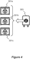
- Figure 4 shows a removable unit 303 and multiple printer devices 301a, 301b, 301c according to Figure 3a and Figure 3c .
- print job instructions for at least one 3D object to be manufactured are supplied to the removable unit 303.
- the removable unit 303 internally stores build materials for the at least one 3D object associated with the print job, e.g. in compartment 331.
- the removable unit 303 engages with a given printer device 301a, 301b, 301c of the 3D print system, and instructs the engaged printer device using the print job instructions from the removable unit 303.
- the engaged printer device (one of 301a, 301b, 301c) is then able to generate the at least one three-dimensional object with the build materials from the removable unit 303.
- a printer device is selected for the print job by engaging the removable unit 303, wherein data for the print job is transferred from the removable unit 303. This allows greater flexibility when controlling a 3D print pipeline and enables more efficient use of available printer devices 301a, 301b, 301c.
- a print application may distribute print jobs between printer devices 301.
- Each printer device 301 may thus have a print queue. If printer device 301a has a number of pending print jobs, any subsequently received print job received by it is added to the end of the queue. A user thus waits for the pending print jobs to complete. This is the case even if one of the other printer devices 301b or 301c is subsequently free.
- the selection of a printer device 301 is made when a particular removable unit 303 storing the print job is engaged. This enables a choice of printer device 301 to be made.
- a different selection of printer device may be made by engaging the removable unit 303 with one of printer devices 301b or 301c rather than printer device 301a. Following engagement, the instructions for the print job are transferred to one of printer devices 301b or 301c and the respective print controller 312 may use these instructions to initiate the print job.
- a waiting removable unit 303 may simpler be moved to wait for another printer device (e.g. 301a or 301c) without reconfiguration of the print queues on the printer devices 301.
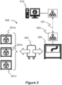
- Figure 5 shows a 3D print system 500 comprising multiple printer devices 501a, 501b, 501c, a material processing station 502 and a removable unit 503 according to an example.
- the printer devices 501a, 501b, 501c, material processing station 502 and removable unit 503 may correspond to those shown in Figures 3a, 3b and 3c .
- instructions for a print job are provided to the 3D print system 500 from a computer device 510 running a print application.
- the print application may comprise a 3D modelling application and/or a print server.
- the print job may be received from a server computer device running a print server, wherein the print server receives the print job from the print application.
- the instructions are relayed to the 3D print system 500 via a network connection 551.
- the network connection 551 couples the computer device 510 and the material processing station 502.
- the network connection 551 may form part of a local area network (LAN) or wide area network (WAN). It may comprise a wired or wireless connection (e.g. an Ethernet or WiFi connection).
- the material processing station 502 comprises a network interface 552 to receive the print job over the network connection 551.
- the material processing station 502 comprises a controller and memory. Following receipt of the print job at the network interface 552, the controller may be configured to store the print job within the memory until a removable unit 503 is engaged.
- the removable unit 503 is engaged with the material processing station 502 so as to perform at least one pre-processing operation before manufacturing a 3D object.
- This engagement may be enacted by mating the coupling 332 of the removable unit 503 with the coupling 321 of the material processing station.
- This may comprise coupling one or more connectors or fasteners and/or engaging a mechanical coupling mechanism to lock the removable unit 503 within the material processing station 502.
- the removable unit 503 comprises castors and is wheeled into position within the coupling of the material processing station 502.
- the material processing station 502 may be arranged to prepare, mix and load the removable unit 503 with the build materials for to completing the 3D print job defined within the received print job.
- a controller of the material processing station 502 is configured to determine an amount of build material to supply to an engaged removable unit 503 based on instructions defining the print job, e.g. as stored in a memory of the material processing station 502.
- a material supply system of the material processing station 502 may be arranged to supply the determined amount of build material from at least one build material supply container to a compartment of the engaged removable unit 503.
- the aforementioned controller may be configured to determine a type of build material to supply to the engaged removable unit based on the instructions in the memory.
- the material supply system may be arranged to supply the determined type of build material from at least one build material supply container containing said type to a compartment of the engaged removable unit 503.
- the controller is configured to control mixing of build material of different types from a respective plurality of build material supply containers based on the instructions in the memory.
- the material processing station 502 is configured to communicate the received print job to the removable unit 503. This may comprise relaying instructions from data transfer interface 323 of the material processing station 502 to the data transfer interface 334 of the removable unit 503, and storing said instructions in the memory 333 of the removable unit 503.
- the transfer or relay of instructions may be performed by transmitting and receiving data over physical or wireless communications interfaces.
- the received print job may be transferred before, during or after the loading of build material into the removable unit.
- the transfer of the print job may be, in one case, initiated by a user interacting with a user interface of the material processing station 502 (e.g. a touchscreen interface).
- a user may be offered an option to download one or more print jobs that are stored in a memory of the material processing station 502 onto the removable unit 503.
- a user may be presented with one or more print jobs that are stored on a remote print server; upon selection by the user these print jobs may be transferred over the network connection 551 and then downloaded into the removable unit 503.
- a print job may be assigned to a particular removable unit 503 by the print application.
- an identifier of an engaged removable unit 503 may be read from the unit by the material processing station 502 and compared with data for at least one print job (stored either locally or remotely). If a match is found, then at least one print job associated with the identifier may be downloaded onto the removable unit 503.
- said unit 503 may be disengaged from the material processing station 502. This may comprise releasing at least one mechanical coupling and/or disconnecting any electrical couplings.
- the removable unit 503 may then be moved, e.g. rolled or carried, to the printer devices 501.
- the removable unit 503 is subsequently engaged with a printer device 501 of the 3D print system 500. Because the print instructions are stored in a memory 333 of the removable unit 503, the removable unit 503 may be engaged with any available printer device 501a, 501b, 501c in the 3D print system 500. Once the removable unit 503 in engaged with a given printer device 501a, 501b, 501c of the 3D print system 500, the instructions may be provided, via the data transfer interface 334 of the removable unit 503, to the data transfer interface 313 of the printer device 501. The print controller 312 of the printer device 501 uses the print job instructions and material from the removable unit 503 to carry out manufacturing of the 3D print object.
- the removable unit 503 may be dis-engaged once more from the printer device 501. This may comprise releasing at least one mechanical coupling and/or disconnecting any electrical couplings. The removable unit 503 may then be moved, e.g. rolled or carried, back to the material processing station 502. Once the removable unit 503 has been re-engaged with the material processing station 502, post-processing steps may be carried out, for example such as: "un-caking" the 3D object (e.g. removing un-fused build material that is still in a powder form); cleaning parts of the 3D object and/or removable unit 503; and/or reclaim leftover build material for recycling or disposal.
- post-processing steps may be carried out, for example such as: "un-caking" the 3D object (e.g. removing un-fused build material that is still in a powder form); cleaning parts of the 3D object and/or removable unit 503; and/or reclaim leftover build material for recycling or disposal.
- Figure 6 shows a 3D print system 600 comprising multiple printer devices 601a, 601b, 601c, multiple material processing stations 602a, 602b, 602c and a removable unit 603 according to an example.
- the printer devices 601a, 601b, 601c, material processing stations 602a, 602b, 602c and removable unit 603 may correspond to those shown in Figures 3a, 3b and 3c .
- instructions for a print job are provided to the 3D print system 600 from a computer device 610 running a print application.
- the print application may comprise a 3D modelling application and/or a print server.
- the print job may be received from a server computer device running a print server, wherein the print server receives the print job from the print application.
- the instructions are relayed to the 3D print system 600 via a network connection 651.
- the network connection 651 couples the computer device 610 and the removable unit 603.
- the network connection 651 may form part of a local area network (LAN) or wide area network (WAN). It may comprise a wired or wireless connection (e.g. an Ethernet or WiFi connection).
- the removable unit 603 comprises a wireless network interface to receive the print job instructions over the wireless network connection 651.
- the removable unit 603 comprises a memory 333, and optionally a controller 335. Following receipt of the print job instructions at a wireless network interface, the memory 333 may be configured to store the print job instructions. In some examples, the instructions are handled by the controller 335 of the removable unit 603.
- the removable unit 303 may be engaged with one of the multiple material processing stations 602a, 602b, 602c. Since the print job instructions are stored on the removable unit 603, the option to engage the removable device 603 with one of a multitude of material processing stations 602a, 602b, 602c provides further benefits to the system 600. For example, if a user intends to utilise a first material processing station 602a, but it is already in use, then an alternative material processing station 602b, 603c may be selected by engaging the removable unit 603 with one of the available material processing stations 602b, 602c in the print system 600, rather than the first, occupied material processing station 602a.
- This engagement may be enacted by mating the coupling 332 of the removable unit 603 with a coupling 321 of the chosen material processing station 602.
- This may comprise coupling one or more connectors or fasteners and/or engaging a mechanical coupling mechanism to lock the removable unit 603 within the material processing station 602.
- the removable unit 603 comprises castors and is wheeled into position within the coupling of the material processing station 602.
- the material processing station 602 comprises a controller and memory. Following receipt of the print job from the engaged removable unit 603, the controller may be configured to store the print job within the memory so as to perform at least one pre-processing operation before manufacturing a 3D object. In one case, the material processing station 602 may be arranged to prepare, mix and load the removable unit 603 with the build materials for completing the 3D print job defined within the received print job instructions. In one case, a controller of the material processing station 602 is configured to determine an amount of build material to supply to the engaged removable unit 603 based on instructions defining the print job instructions, e.g. as stored in a memory of the material processing station 602.
- a material supply system of the material processing station 602 may be arranged to supply the determined amount of build material from at least one build material supply container to a compartment 331 of the engaged removable unit 603.
- the aforementioned controller may be configured to determine a type of build material to supply to the engaged removable unit 603 based on the instructions in the memory.
- the material supply system 602 may be arranged to supply the determined type of build material from at least one build material supply container containing said type to a compartment 331 of the engaged removable unit 603.
- the controller is configured to control mixing of build material of different types from a respective plurality of build material supply containers based on the instructions in the memory.
- the removable unit 603 may be disengaged from the material processing station 602. This may comprise releasing at least one mechanical coupling and/or disconnecting any electrical couplings. The removable unit 603 may then be moved, e.g. rolled or carried, to a printer devices 601.
- the removable unit 603 is subsequently engaged with a printer device 601 of the 3D print system 600.
- the removable unit 603 may be engaged with any one of a plurality of print devices 601a, 601b, 601c, and the manufacturing of the 3D object carried out as described before.
- the removable unit 603 may be dis-engaged once more from the printer device 601. This may comprise releasing at least one mechanical coupling and/or disconnecting any electrical couplings.
- the removable unit 603 may then be moved, e.g. rolled or carried, back to one of the plurality of material processing stations 602a, 602b, 602c for post-processing.
- the removable unit 603 may engage with any available material processing station 602a, 602b, 602c, and importantly, not necessarily the same material processing station 602 used in the pre-processing stage.
- the coupling, decoupling and/or moving of the removable unit 603 to/from at least one of a material processing station 602a, 602b, 602c and print device 601a, 601b, 601c may be fully automated.
- Figure 7 shows a flowchart of an example method 700 of instructing a 3D print system.
- the method comprises supplying print job instructions for at least one three-dimensional object to a removable unit of a three-dimensional print system, wherein the removable unit stores build material for the at least one three-dimensional object.
- the removable unit is engaged with a printer device of the three-dimensional print system.
- the printer device is instructed, using the print job instructions provided by the removable unit, to generate the at least one three-dimensional object with the build materials from the removable unit.
- the removable unit prior to supplying the print job instructions to the removable unit, the removable unit is engaged with a material processing station, and the removable unit is loaded with the build materials for the at least one 3D object.
- supplying the 3D print job instructions to the removable unit comprises engaging the removable unit with a material processing station, and communicating the print job instructions from the material processing station to a memory of the removable unit.
- the print job instructions are sent from a print application to the material processing station.
- supplying print job instructions to the removable unit comprises transmitting the print job instructions to the removable unit using a wireless communications channel.
- Figure 8 shows a non-transitory computer-readable storage medium 800 comprising a set of computer-readable instructions 810, 820, 830.
- a processor 800 of an additive manufacturing system configured to carry out the stored instructions.
- the instructions 810, 820, 830 When executed by the processor 800, they cause the processor to: determine that a build material supply unit is coupled to the additive manufacturing system (block 810); obtain three-dimensional object build data from the build material supply unit (block 820); and build at least one three-dimensional object using the additive manufacturing system according to the object build data (block 830).
- the above examples enable more flexible and efficient device usage in high-productivity 3d printing environments. This includes quicker recovery in the case of a single device failure, and more efficient job queuing.
- the data transfer interface incorporated by any of the printer device 301, material processing station 302 or removable unit 303 may be configured to transfer data by any suitable protocol, for example wireless, Bluetooth ® , wired, radio, infra read, USB, near field communication, etc.
- the initial print instruction receiving device i.e. the material processing station 302 or the removable unit 303 as per the examples described above
- the remaining devices in the 3D print system are "dumb", i.e. not connected to the network.
- all elements of the 3D print system are connected to a network.
- individual 3D print jobs may be tracked by a user at a user terminal through a print application, or another device monitoring application.
- the application may have visibility of each network-connected device in the 3D printing environment and a unique ID of the 3D print job to be tracked.
- a query may be forwarded to each known device on the network searching for a specific job, and the progress of the given 3D print job can be reported back to the user terminal accordingly.
- the various network-connected devices in the 3D print system may use an active eventing model whereby any event related to a specific 3D print job is published and all subscribers to job events receive notifications.
- each 3D print job may be easily tracked, since the submitting application may be provided with information regarding the removable unit that receives the instructions, and the corresponding 3D printer devices and material processing stations that the removable unit engages with.
- the application does not need to scan all of the network material processing stations and 3D printer devices in order to locate and get information about jobs in progress.
- the 3D print system may comprise a plurality of 3D printer devices 101, removable units 103 and material processing stations 102.
- a removable unit 103 may engage with any available 3D printer device, and any available material processing station, not necessarily the same material processing station in the pre-processing stage as in the post-processing stage.
- the 3D print system described above may employ any "pre-load" powder bed fusion (additive manufacturing) method, including, but not limited to: powder bed and inkjet 3D printing; electron beam additive manufacturing; direct metal laser sintering (DMLS); selective heat sintering (SHS); selective laser sintering (SLS); and selective laser melting.
- powder bed and inkjet 3D printing electron beam additive manufacturing
- DMLS direct metal laser sintering
- SHS selective heat sintering
- SLS selective laser sintering
- selective laser melting selective laser melting
Landscapes
- Chemical & Material Sciences (AREA)
- Engineering & Computer Science (AREA)
- Materials Engineering (AREA)
- Manufacturing & Machinery (AREA)
- Physics & Mathematics (AREA)
- Optics & Photonics (AREA)
- Mechanical Engineering (AREA)
- Health & Medical Sciences (AREA)
- Toxicology (AREA)
Claims (15)
- Unité amovible (103, 303) pour un système d'impression tridimensionnelle (100) comprenant :au moins un compartiment (331) pour stocker un matériau de construction à utiliser pendant le traitement d'un travail d'impression tridimensionnelle ;un élément d'accouplement (332) conçu pour venir en prise avec un dispositif d'imprimante (101, 301) du système d'impression tridimensionnelle ;caractérisée en ce que l'unité amovible comprend en outreune mémoire (333) configurée pour stocker des instructions de travail d'impression pour le travail d'impression tridimensionnelle pour le dispositif d'imprimante,dans laquelle la mémoire (333) et l'élément d'accouplement (332) sont configurés de telle sorte que les instructions de travail d'impression sont lisibles à partir de la mémoire par le dispositif d'imprimante lorsque l'élément d'accouplement est mis en prise avec le dispositif d'imprimante (101, 301).
- Unité amovible selon la revendication 1, comprenant :un élément d'accouplement (332) conçu pour venir en prise avec une station de traitement de matériau (102, 302) du système d'impression tridimensionnelle ;dans laquelle la mémoire (333) est configurée pour :
lorsqu'elle est en prise avec la station de traitement de matériau, recevoir et stocker les instructions de travail d'impression pour le travail d'impression à partir de la station de traitement de matériau. - Unité amovible selon la revendication 1, comprenant :un élément d'accouplement (332) conçu pour venir en prise avec une station de traitement de matériau (102, 302) du système d'impression tridimensionnelle ;dans laquelle la mémoire (333) et l'élément d'accouplement (332) sont configurés de telle sorte que des instructions de travail d'impression stockées sur la mémoire sont lisibles par la station de traitement de matériaux lorsque l'élément d'accouplement est mis en prise avec la station de traitement de matériau (102) ; etdans laquelle la station de traitement de matériaux est configurée pour remplir l'au moins un compartiment (331) avec un matériau de construction sur la base de données contenues dans les instructions de travail d'impression.
- Unité amovible selon la revendication 1, comprenant :
une interface réseau sans fil (334) configurée pour recevoir les instructions de travail d'impression pour le travail d'impression à partir d'une application d'impression. - Unité amovible selon la revendication 1, dans laquelle l'élément d'accouplement (332) comprend un élément d'accouplement mécanique et une interface de transfert de données (334) comprenant un élément d'accouplement électrique qui est intégré à l'élément d'accouplement mécanique.
- Station de traitement de matériau (102, 302) pour un système d'impression tridimensionnelle (100) comprenant :un élément d'accouplement (321) conçu pour venir en prise avec une unité amovible (303) selon l'une quelconque revendication précédente ;un système d'alimentation en matériau (322) configuré pour charger une unité amovible en prise avec un matériau de construction à utiliser pendant le traitement d'un travail d'impression tridimensionnelle ; etune interface de transfert de données (323) configurée pour communiquer des instructions de travail d'impression pour le travail d'impression tridimensionnelle entre l'unité amovible en prise et la station de traitement de matériau.
- Station de traitement de matériaux selon la revendication 6, comprenant :une mémoire ; etun dispositif de commande configuré pour communiquer des instructions de travail d'impression pour le travail d'impression tridimensionnelle depuis l'unité amovible en prise à la mémoire de la station de traitement de matériau.
- Station de traitement de matériaux selon la revendication 7,dans laquelle le dispositif de commande est configuré pour déterminer une quantité de matériaux de construction à fournir à l'unité amovible en prise sur la base des instructions de travail d'impression dans la mémoire, etdans laquelle le système d'alimentation en matériau (322) est agencé pour fournir la quantité déterminée de matériaux de construction depuis au moins un récipient d'alimentation en matériaux de construction vers un compartiment de l'unité amovible en prise.
- Station de traitement de matériaux selon la revendication 7,dans laquelle le dispositif de commande est configuré pour déterminer un type de matériau de construction à fournir à l'unité amovible en prise sur la base des instructions de travail d'impression dans la mémoire, etdans laquelle le système d'alimentation en matériau (322) est agencé pour fournir le type déterminé de matériau de construction depuis au moins un récipient d'alimentation en matériaux de construction contenant ledit type à un compartiment de l'unité amovible en prise.
- Station de traitement de matériaux selon la revendication 9, dans laquelle le dispositif de commande est configuré pour commander le mélange de matériaux de construction de différents types provenant d'une pluralité respective de récipients d'alimentation en matériaux de construction sur la base des instructions de travail d'impression dans la mémoire.
- Station de traitement de matériaux selon la revendication 7, comprenant :une interface réseau pour recevoir des instructions de travail d'impression pour le travail d'impression tridimensionnelle à partir d'une application d'impression,dans laquelle le dispositif de commande est configuré pour sauvegarder les instructions de travail d'impression dans la mémoire pour une communication ultérieure à l'unité amovible en prise.
- Station de traitement de matériaux selon la revendication 11, dans laquelle le dispositif de commande est configuré pour :détecter la mise en prise de l'unité amovible par l'intermédiaire de l'élément d'accouplement ; ettransmettre les instructions de travail d'impression pour le travail d'impression tridimensionnelle à l'unité amovible en prise par l'intermédiaire de l'interface de transfert de données.
- Dispositif d'impression (101, 301) pour un système d'impression tridimensionnelle (100) comprenant :un élément d'accouplement (311) conçu pour venir en prise avec une unité amovible (303) selon l'une quelconque des revendications 1 à 5 ;un dispositif de commande d'impression (312) configuré pour utiliser un matériau de construction stocké à l'intérieur d'une unité amovible en prise pour effectuer un travail d'impression tridimensionnelle ; etune interface de transfert de données (313) configurée pour recevoir des instructions de travail d'impression pour le travail d'impression tridimensionnelle à partir de l'unité amovible en prise.
- Dispositif d'imprimante selon la revendication 13, comprenant :un mécanisme de dépôt d'agents d'impression, conçu lorsqu'il est sous la commande du dispositif de commande d'impression (312), pour déposer sélectivement des agents d'impression sur au moins une couche supérieure de matériau de construction sur la base des instructions de travail d'impression pour le travail d'impression tridimensionnelle, etau moins une source d'énergie configurée pour permettre la fusion du matériau de construction après le dépôt d'agents d'impression.
- Dispositif d'impression selon la revendication 14, configuré pour :former successivement des couches de matériau de construction sur une plate-forme de construction de l'unité amovible, etdans lequel l'élément d'accouplement est conçu pour placer la plate-forme de construction de l'unité amovible sous le mécanisme de dépôt d'agents d'impression.
Applications Claiming Priority (1)
| Application Number | Priority Date | Filing Date | Title |
|---|---|---|---|
| PCT/US2016/044694 WO2018022088A1 (fr) | 2016-07-29 | 2016-07-29 | Système d'impression tridimensionnelle |
Publications (3)
| Publication Number | Publication Date |
|---|---|
| EP3436241A1 EP3436241A1 (fr) | 2019-02-06 |
| EP3436241A4 EP3436241A4 (fr) | 2019-12-18 |
| EP3436241B1 true EP3436241B1 (fr) | 2023-11-29 |
Family
ID=61017412
Family Applications (1)
| Application Number | Title | Priority Date | Filing Date |
|---|---|---|---|
| EP16910749.7A Active EP3436241B1 (fr) | 2016-07-29 | 2016-07-29 | Système d'impression tridimensionnelle |
Country Status (7)
| Country | Link |
|---|---|
| US (2) | US11331853B2 (fr) |
| EP (1) | EP3436241B1 (fr) |
| JP (1) | JP6793206B2 (fr) |
| KR (1) | KR102182758B1 (fr) |
| CN (2) | CN109070476A (fr) |
| BR (1) | BR112018072355A2 (fr) |
| WO (1) | WO2018022088A1 (fr) |
Families Citing this family (5)
| Publication number | Priority date | Publication date | Assignee | Title |
|---|---|---|---|---|
| EP3433081A1 (fr) * | 2016-05-12 | 2019-01-30 | Hewlett-Packard Development Company, L.P. | Système de fabrication additive et procédé de post-traitement |
| CN109070476A (zh) * | 2016-07-29 | 2018-12-21 | 惠普发展公司,有限责任合伙企业 | 三维打印系统 |
| FR3061449B1 (fr) * | 2016-12-30 | 2021-03-19 | Viaccess Sa | Cartouche et systeme d'impression de pieces tridimensionnelles |
| CN111136914B (zh) * | 2019-04-16 | 2021-11-26 | 陈宇飞 | 兼容型模具应用平台、方法及存储介质 |
| EP4021705A4 (fr) * | 2020-01-20 | 2023-05-31 | Hewlett-Packard Development Company L.P. | Préparation d'unité de construction |
Family Cites Families (20)
| Publication number | Priority date | Publication date | Assignee | Title |
|---|---|---|---|---|
| US5121329A (en) | 1989-10-30 | 1992-06-09 | Stratasys, Inc. | Apparatus and method for creating three-dimensional objects |
| DE19513536A1 (de) | 1995-04-10 | 1996-10-17 | Heidelberger Druckmasch Ag | Druckmaschine mit mehreren Druckwerken |
| US7725209B2 (en) | 2002-11-12 | 2010-05-25 | Objet Geometries Ltd | Three-dimensional object printing |
| US7939003B2 (en) * | 2004-08-11 | 2011-05-10 | Cornell Research Foundation, Inc. | Modular fabrication systems and methods |
| US7296990B2 (en) * | 2005-10-14 | 2007-11-20 | Hewlett-Packard Development Company, L.P. | Systems and methods of solid freeform fabrication with translating powder bins |
| WO2008103985A2 (fr) | 2007-02-23 | 2008-08-28 | The Exone Company, Llc | Boîte de châssis pouvant être remplacée pour imprimante tridimensionnelle |
| US20090162120A1 (en) | 2007-12-21 | 2009-06-25 | Manico Joseph A | Printer and printing method using receiver medium having adjustable properties |
| US9292230B2 (en) | 2010-05-14 | 2016-03-22 | Canon Europa N.V. | Print management systems |
| CN103764379A (zh) * | 2012-01-26 | 2014-04-30 | 伟尔矿物澳大利亚私人有限公司 | 聚合物复合材料 |
| US20140120196A1 (en) | 2012-10-29 | 2014-05-01 | Makerbot Industries, Llc | Quick-release extruder |
| CA2904648C (fr) * | 2013-03-12 | 2021-05-18 | Orange Maker LLC | Impression 3d utilisant l'accumulation en spirale |
| GB201315036D0 (en) | 2013-08-22 | 2013-10-02 | Renishaw Plc | Apparatus and method for building objects by selective solidification of powder material |
| WO2015027464A1 (fr) | 2013-08-30 | 2015-03-05 | 中国科学院自动化研究所 | Système d'ordonnancement de ressources de fabrication additive selon une informatique en nuage et procédé associé |
| TWI535554B (zh) | 2014-01-06 | 2016-06-01 | 財團法人工業技術研究院 | 立體成型物以及立體成型物的製造設備與製造方法 |
| US10073424B2 (en) | 2014-05-13 | 2018-09-11 | Autodesk, Inc. | Intelligent 3D printing through optimization of 3D print parameters |
| DE102014007408B4 (de) * | 2014-05-21 | 2025-12-04 | Concept Laser Gmbh | System, umfassend eine Vorrichtung zur generativen Herstellung dreidimensionaler Objekte aus pulverartigem Baumaterial |
| DE102014112447B4 (de) | 2014-08-29 | 2025-04-24 | Exone Gmbh | 3D-Drucker, 3D-Druckeranordnung und generatives Fertigungsverfahren |
| JP6498302B2 (ja) * | 2015-01-20 | 2019-04-10 | ヒューレット−パッカード デベロップメント カンパニー エル.ピー.Hewlett‐Packard Development Company, L.P. | メモリを備える取り外し可能な3d造形モジュール |
| CN205291593U (zh) | 2015-11-16 | 2016-06-08 | 岳阳巅峰电子科技有限责任公司 | 一种3d打印机的自动警报加料装置 |
| CN109070476A (zh) * | 2016-07-29 | 2018-12-21 | 惠普发展公司,有限责任合伙企业 | 三维打印系统 |
-
2016
- 2016-07-29 CN CN201680085126.0A patent/CN109070476A/zh active Pending
- 2016-07-29 JP JP2018556871A patent/JP6793206B2/ja active Active
- 2016-07-29 EP EP16910749.7A patent/EP3436241B1/fr active Active
- 2016-07-29 WO PCT/US2016/044694 patent/WO2018022088A1/fr not_active Ceased
- 2016-07-29 KR KR1020187031348A patent/KR102182758B1/ko active Active
- 2016-07-29 BR BR112018072355-0A patent/BR112018072355A2/pt not_active Application Discontinuation
- 2016-07-29 CN CN202610276252.XA patent/CN121821782A/zh active Pending
- 2016-07-29 US US16/097,703 patent/US11331853B2/en active Active
-
2022
- 2022-04-21 US US17/726,478 patent/US11872756B2/en active Active
Also Published As
| Publication number | Publication date |
|---|---|
| US11331853B2 (en) | 2022-05-17 |
| WO2018022088A1 (fr) | 2018-02-01 |
| EP3436241A4 (fr) | 2019-12-18 |
| US11872756B2 (en) | 2024-01-16 |
| EP3436241A1 (fr) | 2019-02-06 |
| US20190152145A1 (en) | 2019-05-23 |
| KR102182758B1 (ko) | 2020-11-26 |
| CN121821782A (zh) | 2026-04-10 |
| CN109070476A (zh) | 2018-12-21 |
| JP6793206B2 (ja) | 2020-12-02 |
| JP2019518628A (ja) | 2019-07-04 |
| BR112018072355A2 (pt) | 2019-02-19 |
| US20220242042A1 (en) | 2022-08-04 |
| KR20180125582A (ko) | 2018-11-23 |
Similar Documents
| Publication | Publication Date | Title |
|---|---|---|
| US11872756B2 (en) | Three-dimensional printing system | |
| EP3433716B1 (fr) | Gestion de l'impression 3d | |
| US11390031B2 (en) | Additive manufacturing system and method for post-processing | |
| KR102325488B1 (ko) | 3차원 물체의 생성 | |
| US20180297278A1 (en) | Smart Cart For Three Dimensional Binder Jet Printers | |
| CN108139734A (zh) | 打印数据生成系统 | |
| CN109532022A (zh) | 基于互联网的3d打印系统和方法 | |
| JP6746286B2 (ja) | 管理システム、それを構成する装置、制御方法、およびプログラム | |
| Bhattacharya et al. | FabRobotics: Fusing 3D Printing with Mobile Robots to Advance Fabrication, Robotics, and Interaction | |
| Kosmal et al. | Hybrid additive robotic workcell for autonomous fabrication of mechatronic systems-A case study of drone fabrication | |
| JP7185965B2 (ja) | Sls3次元印刷のためのロボット式粉体ベッドカート及びそれと両立するプリンターハウジング | |
| JP6953847B2 (ja) | 管理装置および管理プログラム | |
| EP3519160B1 (fr) | Commande d'unité de construction | |
| KR20170143367A (ko) | 3차원 프린터의 제어 방법 | |
| KR20160132687A (ko) | 확장 가능한 3차원 프린팅 장치 및 그 제어방법 | |
| CN104994252B (zh) | 一种3d切片装置控制系统 | |
| US20180257304A1 (en) | Fabrication management system and fabrication management control apparatus | |
| Budzik et al. | Possibilities of Automating the Additive Manufacturing Process of Material Extrusion–MEX | |
| CN119645324A (zh) | 打印机管理方法、计算机设备、存储介质及程序产品 | |
| Katukam | 3d printing of quadcopter: A Case Study | |
| WO2020153943A1 (fr) | Impression d'objets 3d |
Legal Events
| Date | Code | Title | Description |
|---|---|---|---|
| STAA | Information on the status of an ep patent application or granted ep patent |
Free format text: STATUS: THE INTERNATIONAL PUBLICATION HAS BEEN MADE |
|
| PUAI | Public reference made under article 153(3) epc to a published international application that has entered the european phase |
Free format text: ORIGINAL CODE: 0009012 |
|
| STAA | Information on the status of an ep patent application or granted ep patent |
Free format text: STATUS: REQUEST FOR EXAMINATION WAS MADE |
|
| 17P | Request for examination filed |
Effective date: 20181029 |
|
| AK | Designated contracting states |
Kind code of ref document: A1 Designated state(s): AL AT BE BG CH CY CZ DE DK EE ES FI FR GB GR HR HU IE IS IT LI LT LU LV MC MK MT NL NO PL PT RO RS SE SI SK SM TR |
|
| AX | Request for extension of the european patent |
Extension state: BA ME |
|
| RAP1 | Party data changed (applicant data changed or rights of an application transferred) |
Owner name: HEWLETT-PACKARD DEVELOPMENT COMPANY, L.P. |
|
| DAV | Request for validation of the european patent (deleted) | ||
| DAX | Request for extension of the european patent (deleted) | ||
| A4 | Supplementary search report drawn up and despatched |
Effective date: 20191114 |
|
| RIC1 | Information provided on ipc code assigned before grant |
Ipc: B33Y 50/02 20150101ALI20191108BHEP Ipc: B29C 64/393 20170101ALI20191108BHEP Ipc: B29C 64/321 20170101ALI20191108BHEP Ipc: B33Y 40/00 20150101ALI20191108BHEP Ipc: B29C 64/259 20170101ALI20191108BHEP Ipc: B29C 64/307 20170101AFI20191108BHEP |
|
| STAA | Information on the status of an ep patent application or granted ep patent |
Free format text: STATUS: EXAMINATION IS IN PROGRESS |
|
| 17Q | First examination report despatched |
Effective date: 20220228 |
|
| REG | Reference to a national code |
Ref legal event code: R079 Ipc: B29C0064259000 Ref country code: DE Ref legal event code: R079 Ref document number: 602016084479 Country of ref document: DE Free format text: PREVIOUS MAIN CLASS: B29C0064307000 Ipc: B29C0064259000 |
|
| GRAP | Despatch of communication of intention to grant a patent |
Free format text: ORIGINAL CODE: EPIDOSNIGR1 |
|
| STAA | Information on the status of an ep patent application or granted ep patent |
Free format text: STATUS: GRANT OF PATENT IS INTENDED |
|
| RIC1 | Information provided on ipc code assigned before grant |
Ipc: B29C 64/165 20170101ALN20230601BHEP Ipc: B29C 64/153 20170101ALN20230601BHEP Ipc: B33Y 40/20 20200101ALI20230601BHEP Ipc: B33Y 40/10 20200101ALI20230601BHEP Ipc: B33Y 50/02 20150101ALI20230601BHEP Ipc: B29C 64/393 20170101ALI20230601BHEP Ipc: B29C 64/307 20170101ALI20230601BHEP Ipc: B29C 64/259 20170101AFI20230601BHEP |
|
| INTG | Intention to grant announced |
Effective date: 20230615 |
|
| GRAS | Grant fee paid |
Free format text: ORIGINAL CODE: EPIDOSNIGR3 |
|
| GRAA | (expected) grant |
Free format text: ORIGINAL CODE: 0009210 |
|
| STAA | Information on the status of an ep patent application or granted ep patent |
Free format text: STATUS: THE PATENT HAS BEEN GRANTED |
|
| AK | Designated contracting states |
Kind code of ref document: B1 Designated state(s): AL AT BE BG CH CY CZ DE DK EE ES FI FR GB GR HR HU IE IS IT LI LT LU LV MC MK MT NL NO PL PT RO RS SE SI SK SM TR |
|
| REG | Reference to a national code |
Ref country code: GB Ref legal event code: FG4D |
|
| REG | Reference to a national code |
Ref country code: CH Ref legal event code: EP |
|
| REG | Reference to a national code |
Ref country code: DE Ref legal event code: R096 Ref document number: 602016084479 Country of ref document: DE |
|
| REG | Reference to a national code |
Ref country code: IE Ref legal event code: FG4D |
|
| REG | Reference to a national code |
Ref country code: LT Ref legal event code: MG9D |
|
| REG | Reference to a national code |
Ref country code: NL Ref legal event code: MP Effective date: 20231129 |
|
| PG25 | Lapsed in a contracting state [announced via postgrant information from national office to epo] |
Ref country code: GR Free format text: LAPSE BECAUSE OF FAILURE TO SUBMIT A TRANSLATION OF THE DESCRIPTION OR TO PAY THE FEE WITHIN THE PRESCRIBED TIME-LIMIT Effective date: 20240301 |
|
| PG25 | Lapsed in a contracting state [announced via postgrant information from national office to epo] |
Ref country code: IS Free format text: LAPSE BECAUSE OF FAILURE TO SUBMIT A TRANSLATION OF THE DESCRIPTION OR TO PAY THE FEE WITHIN THE PRESCRIBED TIME-LIMIT Effective date: 20240329 |
|
| PG25 | Lapsed in a contracting state [announced via postgrant information from national office to epo] |
Ref country code: LT Free format text: LAPSE BECAUSE OF FAILURE TO SUBMIT A TRANSLATION OF THE DESCRIPTION OR TO PAY THE FEE WITHIN THE PRESCRIBED TIME-LIMIT Effective date: 20231129 |
|
| PG25 | Lapsed in a contracting state [announced via postgrant information from national office to epo] |
Ref country code: ES Free format text: LAPSE BECAUSE OF FAILURE TO SUBMIT A TRANSLATION OF THE DESCRIPTION OR TO PAY THE FEE WITHIN THE PRESCRIBED TIME-LIMIT Effective date: 20231129 |
|
| PG25 | Lapsed in a contracting state [announced via postgrant information from national office to epo] |
Ref country code: LT Free format text: LAPSE BECAUSE OF FAILURE TO SUBMIT A TRANSLATION OF THE DESCRIPTION OR TO PAY THE FEE WITHIN THE PRESCRIBED TIME-LIMIT Effective date: 20231129 Ref country code: IS Free format text: LAPSE BECAUSE OF FAILURE TO SUBMIT A TRANSLATION OF THE DESCRIPTION OR TO PAY THE FEE WITHIN THE PRESCRIBED TIME-LIMIT Effective date: 20240329 Ref country code: GR Free format text: LAPSE BECAUSE OF FAILURE TO SUBMIT A TRANSLATION OF THE DESCRIPTION OR TO PAY THE FEE WITHIN THE PRESCRIBED TIME-LIMIT Effective date: 20240301 Ref country code: ES Free format text: LAPSE BECAUSE OF FAILURE TO SUBMIT A TRANSLATION OF THE DESCRIPTION OR TO PAY THE FEE WITHIN THE PRESCRIBED TIME-LIMIT Effective date: 20231129 Ref country code: BG Free format text: LAPSE BECAUSE OF FAILURE TO SUBMIT A TRANSLATION OF THE DESCRIPTION OR TO PAY THE FEE WITHIN THE PRESCRIBED TIME-LIMIT Effective date: 20240229 |
|
| REG | Reference to a national code |
Ref country code: AT Ref legal event code: MK05 Ref document number: 1635697 Country of ref document: AT Kind code of ref document: T Effective date: 20231129 |
|
| PG25 | Lapsed in a contracting state [announced via postgrant information from national office to epo] |
Ref country code: NL Free format text: LAPSE BECAUSE OF FAILURE TO SUBMIT A TRANSLATION OF THE DESCRIPTION OR TO PAY THE FEE WITHIN THE PRESCRIBED TIME-LIMIT Effective date: 20231129 |
|
| PG25 | Lapsed in a contracting state [announced via postgrant information from national office to epo] |
Ref country code: SE Free format text: LAPSE BECAUSE OF FAILURE TO SUBMIT A TRANSLATION OF THE DESCRIPTION OR TO PAY THE FEE WITHIN THE PRESCRIBED TIME-LIMIT Effective date: 20231129 Ref country code: RS Free format text: LAPSE BECAUSE OF FAILURE TO SUBMIT A TRANSLATION OF THE DESCRIPTION OR TO PAY THE FEE WITHIN THE PRESCRIBED TIME-LIMIT Effective date: 20231129 Ref country code: PL Free format text: LAPSE BECAUSE OF FAILURE TO SUBMIT A TRANSLATION OF THE DESCRIPTION OR TO PAY THE FEE WITHIN THE PRESCRIBED TIME-LIMIT Effective date: 20231129 Ref country code: NO Free format text: LAPSE BECAUSE OF FAILURE TO SUBMIT A TRANSLATION OF THE DESCRIPTION OR TO PAY THE FEE WITHIN THE PRESCRIBED TIME-LIMIT Effective date: 20240229 Ref country code: NL Free format text: LAPSE BECAUSE OF FAILURE TO SUBMIT A TRANSLATION OF THE DESCRIPTION OR TO PAY THE FEE WITHIN THE PRESCRIBED TIME-LIMIT Effective date: 20231129 Ref country code: LV Free format text: LAPSE BECAUSE OF FAILURE TO SUBMIT A TRANSLATION OF THE DESCRIPTION OR TO PAY THE FEE WITHIN THE PRESCRIBED TIME-LIMIT Effective date: 20231129 Ref country code: HR Free format text: LAPSE BECAUSE OF FAILURE TO SUBMIT A TRANSLATION OF THE DESCRIPTION OR TO PAY THE FEE WITHIN THE PRESCRIBED TIME-LIMIT Effective date: 20231129 |
|
| PG25 | Lapsed in a contracting state [announced via postgrant information from national office to epo] |
Ref country code: DK Free format text: LAPSE BECAUSE OF FAILURE TO SUBMIT A TRANSLATION OF THE DESCRIPTION OR TO PAY THE FEE WITHIN THE PRESCRIBED TIME-LIMIT Effective date: 20231129 |
|
| PG25 | Lapsed in a contracting state [announced via postgrant information from national office to epo] |
Ref country code: CZ Free format text: LAPSE BECAUSE OF FAILURE TO SUBMIT A TRANSLATION OF THE DESCRIPTION OR TO PAY THE FEE WITHIN THE PRESCRIBED TIME-LIMIT Effective date: 20231129 Ref country code: AT Free format text: LAPSE BECAUSE OF FAILURE TO SUBMIT A TRANSLATION OF THE DESCRIPTION OR TO PAY THE FEE WITHIN THE PRESCRIBED TIME-LIMIT Effective date: 20231129 |
|
| PG25 | Lapsed in a contracting state [announced via postgrant information from national office to epo] |
Ref country code: SK Free format text: LAPSE BECAUSE OF FAILURE TO SUBMIT A TRANSLATION OF THE DESCRIPTION OR TO PAY THE FEE WITHIN THE PRESCRIBED TIME-LIMIT Effective date: 20231129 |
|
| PG25 | Lapsed in a contracting state [announced via postgrant information from national office to epo] |
Ref country code: SM Free format text: LAPSE BECAUSE OF FAILURE TO SUBMIT A TRANSLATION OF THE DESCRIPTION OR TO PAY THE FEE WITHIN THE PRESCRIBED TIME-LIMIT Effective date: 20231129 Ref country code: SK Free format text: LAPSE BECAUSE OF FAILURE TO SUBMIT A TRANSLATION OF THE DESCRIPTION OR TO PAY THE FEE WITHIN THE PRESCRIBED TIME-LIMIT Effective date: 20231129 Ref country code: RO Free format text: LAPSE BECAUSE OF FAILURE TO SUBMIT A TRANSLATION OF THE DESCRIPTION OR TO PAY THE FEE WITHIN THE PRESCRIBED TIME-LIMIT Effective date: 20231129 Ref country code: IT Free format text: LAPSE BECAUSE OF FAILURE TO SUBMIT A TRANSLATION OF THE DESCRIPTION OR TO PAY THE FEE WITHIN THE PRESCRIBED TIME-LIMIT Effective date: 20231129 Ref country code: EE Free format text: LAPSE BECAUSE OF FAILURE TO SUBMIT A TRANSLATION OF THE DESCRIPTION OR TO PAY THE FEE WITHIN THE PRESCRIBED TIME-LIMIT Effective date: 20231129 Ref country code: DK Free format text: LAPSE BECAUSE OF FAILURE TO SUBMIT A TRANSLATION OF THE DESCRIPTION OR TO PAY THE FEE WITHIN THE PRESCRIBED TIME-LIMIT Effective date: 20231129 Ref country code: CZ Free format text: LAPSE BECAUSE OF FAILURE TO SUBMIT A TRANSLATION OF THE DESCRIPTION OR TO PAY THE FEE WITHIN THE PRESCRIBED TIME-LIMIT Effective date: 20231129 Ref country code: AT Free format text: LAPSE BECAUSE OF FAILURE TO SUBMIT A TRANSLATION OF THE DESCRIPTION OR TO PAY THE FEE WITHIN THE PRESCRIBED TIME-LIMIT Effective date: 20231129 |
|
| PG25 | Lapsed in a contracting state [announced via postgrant information from national office to epo] |
Ref country code: PT Free format text: LAPSE BECAUSE OF FAILURE TO SUBMIT A TRANSLATION OF THE DESCRIPTION OR TO PAY THE FEE WITHIN THE PRESCRIBED TIME-LIMIT Effective date: 20240401 |
|
| PG25 | Lapsed in a contracting state [announced via postgrant information from national office to epo] |
Ref country code: PT Free format text: LAPSE BECAUSE OF FAILURE TO SUBMIT A TRANSLATION OF THE DESCRIPTION OR TO PAY THE FEE WITHIN THE PRESCRIBED TIME-LIMIT Effective date: 20240401 |
|
| REG | Reference to a national code |
Ref country code: DE Ref legal event code: R097 Ref document number: 602016084479 Country of ref document: DE |
|
| PLBE | No opposition filed within time limit |
Free format text: ORIGINAL CODE: 0009261 |
|
| STAA | Information on the status of an ep patent application or granted ep patent |
Free format text: STATUS: NO OPPOSITION FILED WITHIN TIME LIMIT |
|
| PG25 | Lapsed in a contracting state [announced via postgrant information from national office to epo] |
Ref country code: SI Free format text: LAPSE BECAUSE OF FAILURE TO SUBMIT A TRANSLATION OF THE DESCRIPTION OR TO PAY THE FEE WITHIN THE PRESCRIBED TIME-LIMIT Effective date: 20231129 |
|
| PG25 | Lapsed in a contracting state [announced via postgrant information from national office to epo] |
Ref country code: SI Free format text: LAPSE BECAUSE OF FAILURE TO SUBMIT A TRANSLATION OF THE DESCRIPTION OR TO PAY THE FEE WITHIN THE PRESCRIBED TIME-LIMIT Effective date: 20231129 |
|
| 26N | No opposition filed |
Effective date: 20240830 |
|
| PG25 | Lapsed in a contracting state [announced via postgrant information from national office to epo] |
Ref country code: MC Free format text: LAPSE BECAUSE OF FAILURE TO SUBMIT A TRANSLATION OF THE DESCRIPTION OR TO PAY THE FEE WITHIN THE PRESCRIBED TIME-LIMIT Effective date: 20231129 |
|
| REG | Reference to a national code |
Ref country code: CH Ref legal event code: PL |
|
| PG25 | Lapsed in a contracting state [announced via postgrant information from national office to epo] |
Ref country code: LU Free format text: LAPSE BECAUSE OF NON-PAYMENT OF DUE FEES Effective date: 20240729 |
|
| PG25 | Lapsed in a contracting state [announced via postgrant information from national office to epo] |
Ref country code: LU Free format text: LAPSE BECAUSE OF NON-PAYMENT OF DUE FEES Effective date: 20240729 |
|
| PG25 | Lapsed in a contracting state [announced via postgrant information from national office to epo] |
Ref country code: BE Free format text: LAPSE BECAUSE OF NON-PAYMENT OF DUE FEES Effective date: 20240731 Ref country code: CH Free format text: LAPSE BECAUSE OF NON-PAYMENT OF DUE FEES Effective date: 20240731 |
|
| REG | Reference to a national code |
Ref country code: DE Ref legal event code: R081 Ref document number: 602016084479 Country of ref document: DE Owner name: PERIDOT PRINT LLC, PALO ALTO, US Free format text: FORMER OWNER: HEWLETT-PACKARD DEVELOPMENT COMPANY, L.P., SPRING, TX, US Ref country code: GB Ref legal event code: 732E Free format text: REGISTERED BETWEEN 20250410 AND 20250416 |
|
| REG | Reference to a national code |
Ref country code: BE Ref legal event code: MM Effective date: 20240731 |
|
| PGFP | Annual fee paid to national office [announced via postgrant information from national office to epo] |
Ref country code: GB Payment date: 20250619 Year of fee payment: 10 |
|
| PGFP | Annual fee paid to national office [announced via postgrant information from national office to epo] |
Ref country code: FR Payment date: 20250620 Year of fee payment: 10 |
|
| PG25 | Lapsed in a contracting state [announced via postgrant information from national office to epo] |
Ref country code: IE Free format text: LAPSE BECAUSE OF NON-PAYMENT OF DUE FEES Effective date: 20240729 |
|
| PG25 | Lapsed in a contracting state [announced via postgrant information from national office to epo] |
Ref country code: FI Free format text: LAPSE BECAUSE OF FAILURE TO SUBMIT A TRANSLATION OF THE DESCRIPTION OR TO PAY THE FEE WITHIN THE PRESCRIBED TIME-LIMIT Effective date: 20231129 |
|
| PGFP | Annual fee paid to national office [announced via postgrant information from national office to epo] |
Ref country code: DE Payment date: 20250620 Year of fee payment: 10 |
|
| PG25 | Lapsed in a contracting state [announced via postgrant information from national office to epo] |
Ref country code: CY Free format text: LAPSE BECAUSE OF FAILURE TO SUBMIT A TRANSLATION OF THE DESCRIPTION OR TO PAY THE FEE WITHIN THE PRESCRIBED TIME-LIMIT; INVALID AB INITIO Effective date: 20160729 |
|
| PG25 | Lapsed in a contracting state [announced via postgrant information from national office to epo] |
Ref country code: HU Free format text: LAPSE BECAUSE OF FAILURE TO SUBMIT A TRANSLATION OF THE DESCRIPTION OR TO PAY THE FEE WITHIN THE PRESCRIBED TIME-LIMIT; INVALID AB INITIO Effective date: 20160729 |